EP1911654A1 - Carriage-type conveyance device - Google Patents
Carriage-type conveyance device Download PDFInfo
- Publication number
- EP1911654A1 EP1911654A1 EP06781744A EP06781744A EP1911654A1 EP 1911654 A1 EP1911654 A1 EP 1911654A1 EP 06781744 A EP06781744 A EP 06781744A EP 06781744 A EP06781744 A EP 06781744A EP 1911654 A1 EP1911654 A1 EP 1911654A1
- Authority
- EP
- European Patent Office
- Prior art keywords
- turntable
- conveyance carriage
- carriage
- conveyance
- supporting base
- Prior art date
- Legal status (The legal status is an assumption and is not a legal conclusion. Google has not performed a legal analysis and makes no representation as to the accuracy of the status listed.)
- Withdrawn
Links
Images






Classifications
-
- B—PERFORMING OPERATIONS; TRANSPORTING
- B66—HOISTING; LIFTING; HAULING
- B66F—HOISTING, LIFTING, HAULING OR PUSHING, NOT OTHERWISE PROVIDED FOR, e.g. DEVICES WHICH APPLY A LIFTING OR PUSHING FORCE DIRECTLY TO THE SURFACE OF A LOAD
- B66F7/00—Lifting frames, e.g. for lifting vehicles; Platform lifts
- B66F7/06—Lifting frames, e.g. for lifting vehicles; Platform lifts with platforms supported by levers for vertical movement
- B66F7/065—Scissor linkages, i.e. X-configuration
-
- B—PERFORMING OPERATIONS; TRANSPORTING
- B65—CONVEYING; PACKING; STORING; HANDLING THIN OR FILAMENTARY MATERIAL
- B65G—TRANSPORT OR STORAGE DEVICES, e.g. CONVEYORS FOR LOADING OR TIPPING, SHOP CONVEYOR SYSTEMS OR PNEUMATIC TUBE CONVEYORS
- B65G35/00—Mechanical conveyors not otherwise provided for
- B65G35/08—Mechanical conveyors not otherwise provided for comprising trains of unconnected load-carriers, e.g. belt sections, movable in a path, e.g. a closed path, adapted to contact each other and to be propelled by means arranged to engage each load-carrier in turn
-
- B—PERFORMING OPERATIONS; TRANSPORTING
- B61—RAILWAYS
- B61J—SHIFTING OR SHUNTING OF RAIL VEHICLES
- B61J1/00—Turntables; Traversers; Transporting rail vehicles on other rail vehicles or dollies
-
- B—PERFORMING OPERATIONS; TRANSPORTING
- B65—CONVEYING; PACKING; STORING; HANDLING THIN OR FILAMENTARY MATERIAL
- B65G—TRANSPORT OR STORAGE DEVICES, e.g. CONVEYORS FOR LOADING OR TIPPING, SHOP CONVEYOR SYSTEMS OR PNEUMATIC TUBE CONVEYORS
- B65G17/00—Conveyors having an endless traction element, e.g. a chain, transmitting movement to a continuous or substantially-continuous load-carrying surface or to a series of individual load-carriers; Endless-chain conveyors in which the chains form the load-carrying surface
- B65G17/30—Details; Auxiliary devices
- B65G17/48—Controlling attitudes of load-carriers during movement
-
- B—PERFORMING OPERATIONS; TRANSPORTING
- B66—HOISTING; LIFTING; HAULING
- B66F—HOISTING, LIFTING, HAULING OR PUSHING, NOT OTHERWISE PROVIDED FOR, e.g. DEVICES WHICH APPLY A LIFTING OR PUSHING FORCE DIRECTLY TO THE SURFACE OF A LOAD
- B66F7/00—Lifting frames, e.g. for lifting vehicles; Platform lifts
- B66F7/06—Lifting frames, e.g. for lifting vehicles; Platform lifts with platforms supported by levers for vertical movement
Definitions
- the cam rails (59A and 60) for pushing up the cam follower rollers (42a, 42b, and 44) are disposed immediately before the turntable (7).
- the conveyance carriage (1) that exited from the work section (3A) can be sent into the traveling route on the turntable (7) while leaving the object supporting base (17) held at the lifted position.
- the forward route section 3 includes a work section occupying most of the entire length of the forward route section, that is, a work section 3A in which front and after conveyance carriages 1 travel at a low speed in a serial state that they abut against each other, and high-speed traveling sections at both ends of the work section 3A, that is, high-speed traveling sections 3B and 3C in which the front and after conveyance carriages 1 are separated from each other and travel at a high speed.
- Description on the use form of the return route section 4 is omitted, however, it may be constructed similarly to the forward route section 3, or its entire length is set as a high-speed traveling section.
- the conveyance carriage 1 is supported so as to be capable of linearly advancing along the respective traveling routes 3 through 6 by two front and rear sets of a pair of left and right wheels 15 supported on the pair of left and right guide rails 2a and 2b, respectively, laid on the floor surface for forming the respective traveling routes 3 through 6, and two front and rear sets of a pair of left and right vertical shaft rollers 16 which sandwich one oscillation preventive guide rail 2c laid on the inner side of one guide rail 2a from both left and right sides at positions near the front and rear wheels 15, and at the central upper portion, a vertically movable object supporting base 17 is provided, and on the front end, a joining means 18 for joining to a conveyance carriage 1 just in front of said carriage is provided.
- the second cam rail 60 is laid so that, while the cam follower rollers 42a and 42b roll on the uppermost flat surfaces of the start point side first cam rails 59A, the cam follower roller 44 of the second operated portion 40 starts riding onto the second cam rail 60.
- the uppermost flat surfaces are substantially omitted from start point side first cam rails 59A so that the cam follower roller 44 of the second operated portion 40 starts riding onto the second cam rail 60 immediately before the cam follower rollers 42a and 42b come out from the uppermost positions of the start point side first cam rails 59A.
- the conveyance carriage 1 is loaded onto the turntable 7 constructed as described above from the end point of the forward route section 3, and as shown in Fig. 1 , at the end point of the forward route section 3, that is, near the end point of the high-speed traveling route 3B, a cam unit 99 for switching the object supporting base 17 on the conveyance carriage 1 to the lifted position shown in Fig. 4B in the same manner as in sending into the work section 3A before being loaded onto the turntable 7 from the lowered position shown in Fig. 4A , is provided.
- This cam unit 99 uses the start point side first cam rails 59A and second cam rail 60 in the cam unit 58 disposed in the work section 3A, that is, in the cam unit 58 described in detail with reference to Fig. 5 through Figs.
- the conveyance carriage 1 sent onto the turntable 8 is changed in direction by 90 degrees by the turntables 8 through 10, and while sent out to the downstream side traveling routes in a state that the front end of the conveyance carriage is turned toward the downstream side traveling routes (return route section 4, traverse route section 6, and forward route section 3) of the turntables 8 through 10, the conveyance carriage is sent out to the start point of the forward route section 3 via the return route section 4 and the traverse route section 6.
- the object supporting base 17 is lowered from the lifted position to the lowered position at the end point of the work section 3A, and at the end point of the subsequent high-speed traveling section 3B, the object supporting base 17 is switched to the liftedposition again by the cam unit 99, however, depending on the circumstances as in the case where the route length of the high-speed traveling section 3B is short, it is also possible that the conveyance carriage 1 is transferred from the high-speed traveling section 3B onto the turntable 7 while the object supporting base 17 is not lowered to the lowered position but is left held at the lifted position at the end point of the work section 3A.
- the present invention can also be carried out even in a layout in which the object is unloaded from the object supporting base 17 before the conveyance carriage 1 is transferred onto the turntable 7 and the vacant conveyance carriage 1 is changed in direction by the turntable 7.
Landscapes
- Engineering & Computer Science (AREA)
- Mechanical Engineering (AREA)
- Life Sciences & Earth Sciences (AREA)
- Geology (AREA)
- Structural Engineering (AREA)
- Transportation (AREA)
- Intermediate Stations On Conveyors (AREA)
- Automobile Manufacture Line, Endless Track Vehicle, Trailer (AREA)
- Specific Conveyance Elements (AREA)
- Platform Screen Doors And Railroad Systems (AREA)
Abstract
Description
- The present invention relates to a carriage-type conveyance device comprising a vertically movable object supporting base that is controlled by cam rails on the floor side.
- Such a type of carriage-type conveyance device, that is, a carriage-type conveyance device in which an object supporting base vertically movable between a lowered position and a lifted position is provided on a conveyance carriage capable of traveling on a predetermined traveling route, and at the bottom of the conveyance carriage, cam follower rollers vertically moving in association with the movement of the object-supporting base are provided, and in the traveling route of the conveyance carriage, cam rails for pushing up the cam follower rollers and a work section in which the object supporting base is held at the lifted position are provided, is conventionally known as disclosed in
Patent document 1, etc.
Patent document 1:Japanese Published Unexamined Patent Application No. 2004-331366 - In the carriage-type conveyance device constructed as described above, when a turntable for changing the direction of the conveyance carriage is provided in the traveling route of the conveyance carriage, regardless of loading of an object on the object supporting base, the object supporting base is made to ride onto the turntable in a state that the object supporting base is returned to the lowered position. However, in a construction in which object supporting base lifting and lowering cam follower rollers that vertically move in association with the movement of the object supporting base are provided at the bottom of the carriage, when the object supporting base is at the lowered position, the cam follower rollers are at the lower positions at which they come close to the floor surface, and when constructing the turntable, the cam follower rollers at the lower positions must be set so as not to interfere with the turntable side. That is, in the construction in which a pair of left and right guide rails for supporting and guiding the conveyance carriage are laid on the floor surface, to lay the conveyance carriage supporting and guiding guide rails on the turntable at the same level as the above-described guide rails, the upper surface of the turntable must be set at the same level as the floor surface, and as a result, the turntable is housed in a pit dug under the floor surface, and the cost of equipment for changing the direction of the conveyance carriage becomes very high, and in the case of a building structure in which a pit cannot be dug under the floor surface, the direction changing means like a turntable cannot be employed.
- An object of the present invention is to provide a carriage-type conveyance device which can solve the conventional problem as described above, and a carriage-type conveyance device according to a first aspect of the invention includes, as described by attaching the reference numerals in parentheses used in the following embodiment, an object supporting base (17) that is provided on a conveyance carriage (1) capable of traveling on a predetermined traveling route and is vertically movable between a lowered position and a lifted position, cam follower rollers (42a, 42b, 44) that are provided at the bottom of this conveyance carriage (1) and vertically move in association with the object supporting base (17), and in a traveling route of the conveyance carriage (1), cam rails (59A, 60) for pushing up the cam follower rollers (42a, 42b, 44) and a work section (3A) in which the object supporting base (17) is held at the lifted position are provided, wherein
a turntable (7) for changing the direction of the conveyance carriage (1) is disposed in the traveling route on the downstream side of the work section (3A), and
an object supporting base lifted position holding means (locking means (51)) is provided for holding the object supporting base (17) of the conveyance carriage (1) at the lifted position during a period from at least the time immediately before the conveyance carriage (1) enters into the turntable (7) until it exits from the rotated turntable (7). - To carry out the present invention constructed as described above, it is possible that cam rails (59A, 60) for pushing up the object supporting base (17) are laid via the cam follower rollers (42a, 42b, 44) in the entire work section (3A) in which the object supporting base (17) is held at the lifted position or in the entire section in which the object supporting base (17) is held at the lifted position by the object supporting base lifted position holding means (including the whole traveling route on the turntable (7)), however, as described in a second aspect, the conveyance carriage (1) is provided with a means (51) for locking the object supporting base (17) at the lifted position, and at the lowered position to which the object supporting base (17) in the traveling route is lowered, an unlocking means (unlocking cam (61)) for releasing the lock of the locking means (51) is provided, and the cam rails (59A and 60) are laid only at the entrance of the section in which the object supporting base (17) is held at the lifted position, and the object supporting base lifted position holding means can be constituted by the locking means (51).
- When a high-speed traveling section (3B) for high-speed traveling in a state that the object supportingbase (17) is lowered to the lowered position is provided between the work section (3A) and the turntable (7), as described in a third aspect, the cam rails (59A and 60) for pushing up the cam follower rollers (42a, 42b, and 44) are disposed immediately before the turntable (7). In other words, when the turntable (7) is disposed just after the work section (3A), the conveyance carriage (1) that exited from the work section (3A) can be sent into the traveling route on the turntable (7) while leaving the object supporting base (17) held at the lifted position.
- The turntable (7) includes, for example, as described in a fourth aspect, a pair of left and right guide rails (64a and 64b) forming a conveyance carriage traveling route on the turntable (7), an intermediate frame (65) which joins and integrates the guide rails (64a and 64b) on their inner sides, a vertical support shaft (66) provided so as to project from the floor side to axially support this intermediate frame (65) rotatably, a plurality of supporting rollers (67a through 67d) which are attached outside the guide rails (64a and 64b) and roll on a support guide surface (74) on the floor side, and motors (68a and 68b) each of which drives and rotates at least one of the supporting rollers (67a through 67d). In this case, as described in a fifth aspect, it is possible that the supporting rollers (67a through 67d) of the turntable (7) are attached to the intermediate positions in the longitudinal directions of the guide rails (64a and 64b), other supporting auxiliary rollers (69a through 69d) are attached to the ends of the guide rails (64a and 64b), and auxiliary support guide surfaces (75 and 76) which levels the ends of the guide rails via the supporting auxiliary rollers (69a and 69c) or (69b and 69d) adjacent to the ends of the upstream side traveling route or the downstream side traveling route when the conveyance carriage traveling route on the turntable (7) is connected to this traveling route are provided on the floor side.
- Furthermore, when the conveyance carriage (1) is a self-propelled type, according to self-traveling of the conveyance carriage (1), the conveyance carriage can be made to ride onto the turntable (7) and exit from the turntable (7), however, when the conveyance carriage (1) is not a self-propelled type or can be switched into a freely movable state although it is a self-propelled type, the conveyance carriage (1) can be made to ride onto the turntable (7) and exit from the turntable (7) by a drive means disposed on the traveling route side. For example, as described in a sixth aspect, a conveyance carriage loading means (81) for loading onto the turntable (7) from the upstream side traveling route and a conveyance carriage unloading means (82) for unloading from the turntable (7) onto the downstream side traveling route are disposed on the floor side, these conveyance carriage loading means (81) and conveyance carriage unloading means (82) on the floor side include friction drive wheels (83, 85) that are brought into pressure contact with one of the left and right side surfaces parallel to the traveling direction provided on the conveyance carriage (1) and backup rollers (84, 86) that are brought into contact with the other one, and the turntable (7) is constructed so that the turntable (7) is driven to rotate forward and reverse in a range between a position (conveyance carriage receiving position) at which one end of the conveyance carriage traveling route on the turntable (7) is connected to the upstream side traveling route and a position (conveyance carriage outgoing position) at which the other end of the conveyance carriage traveling route on the turntable (7) is connected to the downstream side traveling route, the friction drive wheel (83) of the conveyance carriage loading means (81) is disposed on the floor side on the side fromwhich the conveyance carriage (1) loaded onto the turntable (7) moves away according to the rotation of the turntable (7), the friction drive wheel (85) of the conveyance carriage unloading means (82) is disposed on the floor side on the side which the conveyance carriage (1) on the turntable (7) approaches according to the rotation of the turntable (7), and backup rollers (84 and 86) of the conveyance carriage loading means (81) and the conveyance carriage unloading means (82) are made to freely exit from the inside to the outside of the rotation space of the conveyance carriage (1) on the turntable (7) according to the rotation of the turntable (7).
- When the construction described in the sixth aspect is employed, as described in a seventh aspect, on the end of the upstream side traveling route (forward route (3)) to which the conveyance carriage traveling route on the turntable (7) is connected, a normally-closed stopper (90) that can freely stand and fall for preventing dropping-off of the conveyance carriage is provided, and a cam means (cam rail (94)) which interlocks with entering and exiting movements of the backup roller (84) of the conveyance carriage loading means (81) is provided so that thecammeans (camrail (94)) switches thenormally-closedstopper (90) to an unworking position by interlocking with the exiting movement of the backup roller (84) of the conveyance carriage loading means (81).
- According to the carriage-type conveyance device described in the first aspect of the invention, when the conveyance carriage is changed in direction by a turntable, the object supporting base of the conveyance carriage is held at the lifted position by the object supporting base lifted position holding means from at least the time immediately before the carriage enters into the turntable until it completely exits from the turntable, and therefore, the cam follower rollers at the bottom of the carriage for lifting and lowering the object supporting base are also lifted to the upper position. Therefore, even when the pair of left and right guide rails of the traveling route including the work section are laid on the floor surface and the lower positions of the cam follower rollers at the bottomof the carriage (positions of the cam follower rollers when the object supporting base is at the lowered position) are set close to the floor surface between the pair of left and right guide rails, it becomes unnecessary to secure a space for moving the cam follower rollers at the lower position between the pair of left and right guide rails forming the traveling route on the turntable. Therefore, the pair of left and right guide rails forming the traveling route on the turntable can be joined and integrated together on the inner sides of the guide rails so that the turntable can be formed to be thin, and it becomes unnecessary to provide the conventional pit into which the guide rail lower portion of the turntable fits by digging the floor surface, so that the cost of equipment can be significantly reduced.
- According to the construction described in the second aspect and the third aspect, it becomes unnecessary to lay cam rails for pushing up the cam follower rollers of the conveyance carriage on the turntable and on the entire region of the work section, so that the cost of the entire equipment including the turntable can be further reduced.
- According to the construction described in the fourth aspect, the turntable for changing the direction of the conveyance carriage can be easily formed to be thin, however, in this case, according to the construction described in the fifth aspect, the rotation radius of the main supporting roller is reduced, and even when the support guide surface on the floor side is formed of a separate plate member laid on the floor, the radius of this separate plate member can be made small and the cost can be reduced, and in addition, the ends of the guide rails on the turntable on the side onto which the conveyance carriage is transferred are reliably supported at a predetermined level by auxiliary support guide surfaces on the floor side, and the conveyance carriage can be safely and smoothly transferred.
- Furthermore, according to the construction described in the sixth aspect, even a conveyance carriage that is not a self-propelled type can be transferred onto the turntable by a friction drive method, and friction drive wheels and backup rollers as friction drive means necessary in this case are not mounted on the turntable but are installed by dividing these for the conveyance carriage loading means and the conveyance carriage unloading means on the floor side, so that the necessary strength of the turntable can be lowered, whereby the invention can be easily carried out as a thin and light-weight turntable. When rotating the turntable, it is necessary to prevent the friction drive means from obstructing this rotation, and according to the construction described in the seventh aspect, only the backup roller side including no drive source is moved, so that the construction of the entire turntable including the conveyance carriage drive means is simplified, and can be carried out inexpensively. On the end of the upstream side traveling route to which the traveling route on the turntable is not connected, a normally-closed stopper for preventing dropping-off of the conveyance carriage is necessary, and in this case, according to the construction described in the seventh aspect, an actuator for moving the backup rollers in the means for loading the conveyance carriage onto the turntable to exit prior to the turntable rotation can be used commonly as an actuator for automatically switching the normally-closed stopper to the unworking position when connecting the turntable, so that the control becomes easier than in the case where an actuator exclusive for the normally-closed stopper is provided, so that the cost of the equipment can also be further reduced.
-
-
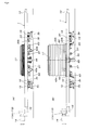
Fig. 1 is a partially cut-away plan view showing the entire layout; -
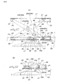
Fig. 2A is a schematic partially longitudinal sectional side view describing the entire construction of a conveyance carriage;Fig. 2B is a longitudinal sectional side view of a main portion showing a state before joining operation of joining means; andFig. 2C is a longitudinal sectional side view of a main portion showing a joining state of the same joining means; -
Fig. 3 is a schematic plan view describing the entire construction of the conveyance carriage; -
Fig. 4A is a back view of the conveyance carriage in a state that an object supporting base is at a lowered position, andFig. 4B is a back view of the conveyance carriage in a state that the object supporting base is at a lifted position; -
Fig. 5 is a longitudinal sectional side view of a main portion showing a state immediately before the object supporting base starts being lifted from the lowered position; -
Fig. 6 is a longitudinal sectional side view of a main portion showing a state when the object supporting base is lifted to a middle height; -
Fig. 7 is a longitudinal sectional sideviewof amainportion showing a state when the object supporting base reaches the lifted position; -
Fig. 8 is a longitudinal sectional back view in the state ofFig. 7 ; -
Fig. 9 is a plan view of a main portion showing a state when the object supporting base is at the lowered position; -
Fig. 10 is a longitudinal sectional side view of a main portion showing a state when the object supporting base is lowered from the lifted position to the middle height; -
Fig. 11A is a longitudinal sectional side view of a main portion showing a state immediately before the object supporting base is unlocked from the lifted position, andFig. 11B is a longitudinal sectional side view of a main portion showing a state when the object supporting base is unlocked from the lifted position; -
Fig. 12 is a plan view showing a state that a turntable for changing the direction of the conveyance carriage is connected to an upstream side traveling route; -
Fig. 13 is a plan view showing a state that a turntable for changing the direction of the conveyance carriage is connected to a downstream side traveling route; -
Fig. 14 is a side view of a main portion ofFig. 12 ; -
Fig. 15 is a front view showing a turntable main body portion ofFig. 12 ; -
Fig. 16 is a front view showing a turntable main body portion ofFig. 12 and a conveyance carriage loading means; -
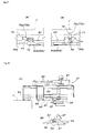
Fig. 17A is a front view of a main portion showing a state when carriage drop-off stoppers at both front and rear ends of the turntable are in a fall-down unworking posture, andFig. 17B is a plan view of a main portion showing a state when the same carriage drop-off stoppers are in a standing working posture; -
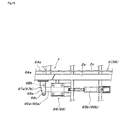
Fig. 18A is a plan view showing an entering and exiting drive means for backup rollers in a conveyance carriage loading means provided for the turntable and a normally-closed stopper for preventing dropping-off of the conveyance carriage from a position on the forward route section; andFig. 18B is a side view showing only the same normally-closed stopper; and -
Fig. 19 is a plan view showing a turntable positioning means. -
- 1
- conveyance carriage
- 2a, 2b
- guide rail
- 2c
- oscillation preventive guide rail
- 3
- forward route section
- 3B, 3C
- high-speed traveling section
- 3A
- work section
- 4
- return route section
- 5, 6
- traverse route section
- 7-10
- turntable for changing the direction of conveyance carriage
- 11A
- rear-pushing drive means
- 11B
- braking drive means
- 11C
- high-speed drive means
- 11D
- variable-speed drive means
- 12, 83, 85
- friction drive wheel
- 13, 84, 86
- backup roller
- 14, 83a, 85a
- motor for driving friction drive wheel
- 15
- wheel
- 16
- oscillation preventive vertical shaft roller
- 17
- vertically movable object supporting base
- 18
- joining means
- 20
- joining device
- 22
- joining device opening cam rail
- 22b
- joining device opening cam follower roller
- 23
- crosslink mechanism for lifting and lowering object supporting base
- 24a, 24b
- crosslink
- 33, 38
- slide guide
- 39
- first operated portion
- 40
- second operated portion
- 42a, 42b
- cam follower roller of first operated portion
- 43
- toggle link
- 44
- cam follower roller of second operated portion
- 51
- locking means of object supporting base
- 52
- locking means engaged portion
- 53
- locking means engagement device
- 57
- cam follower roller of locking means engagement device
- 58, 99, 100
- cam unit for object supporting base vertical movement control
- 59A
- start point side first cam rail
- 59B
- end point side first cam rail
- 60
- second cam rail
- 61
- unlocking cam
- 62
- carriage floating preventive cam rail
- 63
- carriage floating preventive backup roller
- 64a, 64b
- guide rail on turntable
- 65
- intermediate frame
- 66
- rotation center vertical support shaft of turntable
- 67a-67d
- turntable supporting roller
- 68a, 68b
- turntable drive motor
- 69a-69d
- turntable supporting auxiliary roller
- 70a, 70b
- carriage drop-off stopper
- 71
- annular support plate
- 72a, 72b
- turntable rotation limiting stopper
- 74
- support guide surface
- 75, 76
- auxiliary support guide surface
- 78
- stopper main body
- 79
- cam follower roller
- 80a, 80b
- carriage drop-off stopper controlling cam rail
- 81
- conveyance carriage loading means
- 82
- conveyance carriage unloading means
- 87
- backup roller entering and exiting drive cylinder unit
- 88
- movable base
- 89
- conveyance carriage positioning means
- 90
- normally-closed stopper
- 92
- stopper main body
- 93
- cam follower roller
- 94
- normally-closed stopper controlling cam rail
- 95, 96
- turntable positioning means
- 95a, 96a
- engagement device
- 95b, 96b
- engagement device entering and exiting drive cylinder unit
- 97a, 97b
- positioning engaged portion
- Hereinafter, a detailed embodiment of the present invention will be described with reference to the accompanying drawings. In
Fig. 1 , thereference numeral 1 denotes a conveyance carriage which travels on a cyclic traveling route formed of a pair of left andright guide rails forward route section 3 and areturn route section 4 which are arranged linearly in parallel to each other, traverseroute sections route sections turntables 7 through 10 for changing the direction of the conveyance carriage, connecting the ends of theroute sections traverse route sections route sections forward route section 3 includes a work section occupying most of the entire length of the forward route section, that is, awork section 3A in which front and afterconveyance carriages 1 travel at a low speed in a serial state that they abut against each other, and high-speed traveling sections at both ends of thework section 3A, that is, high-speed traveling sections 3B and 3C in which the front and afterconveyance carriages 1 are separated from each other and travel at a high speed. Description on the use form of thereturn route section 4 is omitted, however, it may be constructed similarly to theforward route section 3, or its entire length is set as a high-speed traveling section. - At the entrance of the
work section 3A, a rear-pushing drive means 11A which propels theconveyance carriage 1 at a constant speed is provided, and the exit of the work section, a braking drive means 11B for forwarding theconveyance carriage 1 at a constant speed is provided. In the high-speed traveling sections 3B and 3C, high-speed drive means 11C which propel theconveyance carriages 1 at a high speed are disposed at the intervals equal to or slightly shorter than the entire length of theconveyance carriage 1, and at the terminal ends of the high-speed traveling sections 3B and 3C, variable speed drive means 11D which reduce the traveling speed of theconveyance carriage 1 to a predetermined speed and then forward it are disposed. In the respectivetraverse route sections conveyance carriages 1 unloaded from theturntables 7 through 9 on the upstream side and then load the conveyance carriages onto the turntables 8 through 10 on the downstream side when the turntables 8 through 10 on the downstream side turn into a conveyance carriage accepting state are disposed. Of course, when the route lengths of thetraverse route sections return route section 4, although the drive means are omitted from illustration, appropriate drive means 11A through 11D are disposed according to the use form of this return route section. - By disposing the drive means 11A through 11D, in the
work section 3A, the front and afterconveyance carriages 1 become serial in a state that their ends are in contact with each other (abutting state), and at the entrance of thework section 3A, allconveyance carriages 1 in thework section 3A are pushed from the rear side and driven at a constant speed by therearmost conveyance carriage 1 driven by the rear-pushing drive means 11A. At this time, the braking drive means 11B at the entrance of thework section 3A is driven at a torque lower than that of the rear-pushing drive means 11A and at a speed slightly lower than the drive speed of the rear-pushing drive means 11A, and by braking theforefront conveyance carriage 1 in thework section 3A, it is prevented that theconveyance carriage 1 pushed from the rear side travels at a speed more than the constant speed due to inertia and causes a gap between theconveyance carriages 1, and theconveyance carriages 1 are forwarded one by one at a constant speed from the inside of thework section 3A. Theconveyance carriages 1 in the high-speed traveling sections 3B and 3C travel at a high speed while maintaining a predetermined interval between the front and afterconveyance carriages 1, and are reduced in speed to a fixed low speed by the variable speed drive means 11D at the terminal end and forwarded to the downstream side. - Each of the drive means 11A through 11D uses a friction drive means constituted by a combination of a
friction drive wheel 12 and abackup roller 13 sandwiching the left and right side surfaces (friction drive surfaces) of theconveyance carriage 1 whose two-dimensional shape is in a rectangular shape long in the traveling direction. Thefriction drive wheel 12 is driven by amotor 14. - As shown in
Figs. 2 through Figs. 4 , theconveyance carriage 1 is supported so as to be capable of linearly advancing along therespective traveling routes 3 through 6 by two front and rear sets of a pair of left andright wheels 15 supported on the pair of left andright guide rails respective traveling routes 3 through 6, and two front and rear sets of a pair of left and rightvertical shaft rollers 16 which sandwich one oscillationpreventive guide rail 2c laid on the inner side of oneguide rail 2a from both left and right sides at positions near the front andrear wheels 15, and at the central upper portion, a vertically movableobject supporting base 17 is provided, and on the front end, a joiningmeans 18 for joining to aconveyance carriage 1 just in front of said carriage is provided. This joining means 18 includes a joiningdevice 20 which is long in the front and rear direction and axially supported on the front end lower side of theconveyance carriage 1 so as to be capable of making a seesaw motion by thehorizontal support shaft 19, and this joiningdevice 20 is provided with aweight portion 20a and acam follower roller 20b at the rear end, and on the front end, an engagingportion 20c is continuously provided upward, and as shown inFig. 2C , due to a downward urging force acting on the rear end side (a spring such asweight portion 20a, etc. , can also be used at the same time), when the rear half of the joiningdevice 20 is received by a receivingmember 21 on theconveyance carriage 1 side and this joiningdevice 20 turns into a substantially horizontal posture, the engagingportion 20c enters from below the inner side of the rear end left-to-rightlateral member 1a of aconveyance carriage 1 right in front of the above-describedconveyance carriage 1 which comes into contact with the front end of the above-describedconveyance carriage 1 so that thisfront conveyance carriage 1 can be prevented from moving ahead. - As shown in
Fig. 2B , according to riding onto thecam follower roller 20b onto the joining deviceopening cam rail 22 laid on the traveling route side, the engagingportion 20c tilts so as to lower against the urging force and the joiningdevice 20 is switched from the joining posture into an opening posture, and the engagingportion 20c separates downward from the rear end left-to-rightlateral member 1a of the immediately infront conveyance carriage 1, and allows this immediately infront conveyance carriage 1 to move ahead. Then, the joining deviceopening cam rail 22 is disposed at the entrance and exit of thework section 3A as shown inFig. 1 , and thecam rail 22 on the entrance side of thework section 3A switches the joiningdevice 20 of theconveyance carriage 1 that is about to enter thework section 3A to the above-described opening posture and allows the front end of thisconveyance carriage 1 to come into contact with the rear end of therearmost conveyance carriage 1 entering in thework section 3A, and according to subsequent restoration of the joiningdevice 20 into the joining posture, automatically engages the engagingportion 20c of the joiningdevice 20 with the rear end left-to-rightlateral member 1a of the immediately infront conveyance carriage 1, and thecam rail 22 on the exit side of thework section 3A switches the joiningdevice 20 of the afterconveyance carriage 1 in a joined state to thefront conveyance carriage 1 that is about to exit from thework section 3A into an opening posture to enable thefront conveyance carriage 1 to move ahead (rear side forward movement). - Next, lifting and lowering drive means of the
object supporting base 17 on theconveyance carriage 1 will be described in detail with reference toFig. 5 through Figs. 11 . Theobject supporting base 17 is supported vertically movably by acrosslink mechanism 23 interposed between theobject supporting base 17 and theconveyance carriage 1 on the lower side of theobject supporting base 17. Thiscrosslink mechanism 23 is constructed by parallely arranging twocrosslinks object supporting base 17. - The pair of left and
right crosslinks crosslink mechanism 23 consist of twolinks center pivot shafts 27, and among each twolinks 25a through 26b, the front ends of thelinks right bearing members 29 provided on asupport frame 28 on theconveyance carriage 1 side by concentric position fixingpivot shafts 30 so as to be able to swing vertically, and the rear ends of thelinks slide pivot shaft 31, androllers 32 axially supported on both ends of the commonslide pivot shaft 31 are fitted to a pair of left and right front-to-rear slide guides 33 provided on the rear end lower side of theobject supporting base 17 so as to roll in the front and rear direction. Among each twolinks 25a through 26b, the front ends of thelinks right bearing members 34 provided just above the pair of left andright bearing members 29 on the front end lower side of theobject supporting base 17 by position fixingpivot shafts 35 concentric with each other so as to vertically swing, the rear ends of thelinks slide pivot shaft 36, and therollers 37 supported on both ends of the commonslide pivot shaft 36 are fitted to a pair of left and right front-to-rear slide guides 38 provided just below the front-to-rear slide guides 33 on thesupport frame 28 on theconveyance carriage 1 side so as to roll in the front and rear direction. - The
crosslink mechanism 23 is provided with first operatedportion 39 and second operatedportion 40. The first operatedportion 39 consists ofcam follower rollers projections links links 25a through 26b which constitute the pair of left andright crosslinks projections central pivot shafts 27 at the intermediate positions between thecentral pivot shafts 27 of thelinks slide pivot shaft 31, and when theobject supporting base 17 is at the lowering limit height as shown inFig. 5 , they project downward from theconveyance carriage 1 so that thecam follower rollers - The second operated
portion 40 is formed of onecam follower roller 44 axially supported on atoggle link 43 provided in thecrosslink mechanism 23. Thetoggle link 43 is constructed by joining alonger link 45 and ashorter link 46 to each other by anintermediate bendpivot shaft 47 , and thelinks single bodies cam follower roller 44 is supported by the intermediatebend pivot shaft 47 between the linksingle bodies longer link 45 on the inner side. Thistoggle link 43 is disposed substantially at the center between the pair of left andright crosslinks central pivot shafts 27 of thelinks crosslinks slide pivot shaft 31 by a shaft-like cross member (support shaft member) 48 laid across thelinks shorter links 46 are pivotally attached to the bearingmembers 49 attached onto thesupport frame 28 on theconveyance carriage 1 side by asupport shaft 50 positioned below thecentral pivot shaft 27 of thecrosslinks - As shown in
Fig. 8 ,Fig. 9 , andFig. 11 , in thecrosslink mechanism 23 , a locking means 51 for locking theobject supporting base 17 at the lifted position is provided. This locking means 51 uses the commonslide pivot shaft 36 laid across thelinks crosslinks portion 52, and includes a pair of left andright engagement devices 53 which automatically engage with the engagedportion 52. Theengagement devices 53 have the same structure and are disposed in a left and right distributing state with respect to the second operatedportion 40 so as to be at the intermediate positions between the pair of left and rightcam follower rollers portion 39 and onecam follower roller 44 of the second operatedportion 40, and the engagement devices are held by gravity at home positions at which the engagement devices are axially supported onto the bearingmembers 54 provided on thesupport frame 28 on theconveyance carriage 1 side by concentric left and righthorizontal support shafts 55 so as to swing vertically, andcontact members 56 attached to therespective engagement devices 53 are received by the bearingmembers 54. To theengagement devices 53,arms 53a are continuously and integrally provided downward, and on the lower ends of thearms 53a,cam follower rollers 57 are axially supported via the concentric left and right horizontal support shafts. Thecam follower rollers 57 project further downward than the bottom surface of theconveyance carriage 1. - The
object supporting base 17 is lowered due to gravity at the lowered position shown inFig. 5 and stabilizes there in normal conditions. The height of theobject supporting base 17 at this time can be determined by a support device capable of adjusting the height stood on theconveyance carriage 1 side (conventionally known device, not shown). When theobject supporting base 17 is thus at the lowered position, the pair of left andright crosslinks crosslink mechanism 23 are in a fall-down state as shown inFig. 5 , and the pair of left and rightcam follower rollers portion 39 project by a maximum amount downward from the bottom surface of theconveyance carriage 1. Then, thecam follower roller 44 of the second operatedportion 40 is substantially at the same level as thecam follower rollers portion 39, and thetoggle link 43 having thiscam follower roller 44 is folded so that both of free end pivots (cross member (support shaft member) 48 and support shaft 50) of thelinks conveyance carriage 1 with respect to thecam follower roller 44. Therefore, in this state, it is not possible that thecam follower roller 44 is pushed up to stand thecrosslink - On the other hand, in the
work section 3A in the traveling route of theconveyance carriage 1, acam unit 58 for object supporting base vertical movement control and the like is provided. Thiscam unit 58 is composed of cam rails 59A, 59B, 60, and 61 describedbelow. In detail, on the start point of thework section 3A (seeFig. 1 ), as shown inFig. 5 , a pair of left and right start point side first cam rails 59A which pushes up the pair of left and rightcam follower rollers portion 39 according to the forward traveling of theconveyance carriage 1 are laid, and on the end point of thework section 3A, as shown inFig. 10 , a pair of left and right end point side first cam rails 59B which receive the pair of left and rightcam follower rollers portion 39 being lowered and then lower thecam follower rollers conveyance carriage 1 are laid, and furthermore, in thework section 3A from a position near the end point of the start point side first cam rails 59A to a position near the start point of the end point side first cam rails 59B, asecond cam rail 60 which pushes up thecam follower roller 44 of the second operatedportion 40 according to the forward traveling of theconveyance carriage 1 and holds it at a predetermined height is laid. - Then, when the
conveyance carriage 1 enters into thework section 3A, as shown inFig. 6 , the pair of left and rightcam follower rollers portion 39 ride onto the pair of left and right start point side first cam rails 59A, and the pair of left and right start point sidefirst cam rails 59A pushes up thelinks right crosslinks cam follower rollers right crosslinks object supporting base 17 supported by the pair of left andright crosslinks - As shown in
Fig. 6 , when the pair of left and rightcam follower rollers object supporting base 17 reaches the predetermined middle height H1, and according to the standing movement of thecrosslinks object supporting base 17 from the lowered position to the middle height H1, thetoggle link 43 is slightly developed from the folded state shown inFig. 5 into a V-shaped state, and thecam follower roller 44 moves rearward substantially at the same level, and the free end pivots (cross member (support shaft member) 48 and support shaft 50) of thetoggle link 43 are arranged so as to be distributed to the front side and the rear side with respect to the cam follower roller44. Therefore, in this state, bypushingup thecam follower roller 44, thetoggle link 43 can be further developed and thecrosslinks - The
second cam rail 60 is laid so that, while thecam follower rollers cam follower roller 44 of the second operatedportion 40 starts riding onto thesecond cam rail 60. Of course, it is also possible that the uppermost flat surfaces are substantially omitted from start point side first cam rails 59A so that thecam follower roller 44 of the second operatedportion 40 starts riding onto thesecond cam rail 60 immediately before thecam follower rollers - Then, as the
cam follower roller 44 of the second operatedportion 40 rides onto thesecond cam rail 60 according to the traveling of theconveyance carriage 1, theshorter links 46 of thetoggle link 43 swing upward around thesupport shaft 50, and the longer links 45 push up thecrosslinks cam follower roller 44 reaches the uppermost flat surface of thesecond cam rail 60, as shown inFig. 7 , thecrosslinks object supporting base 17 rise from the middle height H1 to the lifted position H2. - As described above, when the
crosslinks object supporting base 17 is lifted, the upper and lower commonslide pivot shafts right crosslinks rollers object supporting base 17 reaches the lifted position H2, the common slide pivot shaft 36 (engaged portion 52) on the lower side passes through the pair of left andright engagement devices 53 of the locking means 51 while pushing up the engagement devices via the inclined surface on the tip end lower side thereof, and when theobject supporting base 17 reaches the lifted position H2, that is, when thecam follower roller 44 of the second operatedportion 40 reaches the uppermost flat surface of thesecond cam rail 60, recessed engagingportions 53b of the pair of left andright engagement devices 53 fit and engage with this lower common slidepivot shaft 36 (engaged portion 52) from above due to gravity. Of course, springs for forcibly urging therespective engagement devices 53 downward can also be used. - That is, when the
conveyance carriage 1 enters into thework section 3A, theobject supporting base 17 positioned at the lowered position is automatically lifted to the lifted position H2, and at this time, as described above, theengagement devices 53 of the locking means 51 automatically engage with the engaged portions 52 (lower common slide pivot shaft 36) of thecrosslinks right crosslinks object supporting base 17 lowers from the lifted position H2, rearward sliding of the common slide pivot shaft 36 (engaged portions 52) of thecrosslinks engaging portions 53b of theengagement devices 53 engaging with this common slide pivot shaft 36 (engaged portions 52), so that even if thetoggle link 43 axially supporting thecam follower roller 44 pushed up by thesecond cam rail 60 is bent or broken while theconveyance carriage 1 travels in thework section 3A in which theobject supporting base 17 is lifted to the lifted position, theobject supporting base 17 can be prevented from dropping from the lifted position H2. - Immediately before the end point of the
work section 3A, as shown inFigs. 11 , unlockingcams 61 are laid. The unlockingcams 61 are disposed on the left and right sides of thesecond cam rail 60 corresponding to therespective engagement devices 53 so that thecam follower rollers 57 of theengagement devices 53 ride onto these according to the traveling of theconveyance carriage 1, and thecam follower rollers 57 ride onto these unlockingcams 61 and theengagement devices 53 swing upward against gravity, the recessedengaging portions 53b of theengagement devices 53 are released upward from the common slide pivot shaft 36 (engaged portions 52) of thecrosslinks crosslinks - After the above-described unlocking operation, the
conveyance carriage 1 reaches the end point of thework section 3A, and thecam follower roller 44 of the second operatedportion 40 becomes capable of descending the down slope at the end point of thesecond cam rail 60 according to traveling of theconveyance carriage 1, so that theobject supporting base 17 lowers while making thecrosslinks Fig. 10 , when theobject supporting base 17 reaches the middle height H1 according to the traveling of theconveyance carriage 1, that is, at the time immediately before thecam follower roller 44 separates from thesecond cam rail 60, the pair of left and rightcam follower rollers portion 39 are received by the uppermost flat surfaces of the pair of left and right end point side first cam rails 59B, and according to subsequent traveling of theconveyance carriage 1, thecam follower rollers object supporting base 17 further lowers from the middle height H1 while making thecrosslinks conveyance carriage 1 exits from thework section 3A, thecam follower rollers crosslinks object supporting base 17 returns to the lowered position that is the home position. - To the
cam unit 58, carriage floating preventive cam rails 62 shown inFig. 4B can be added. That is, at appropriate positions on the bottom of theconveyance carriage 1, preferably, at the position just below the center of theobject supporting base 17 in a side view and two left and right symmetrical positions with respect to the center in the left and right width direction of theconveyance carriage 1 in a front view,backup rollers 63 are axially supported by the horizontal support shafts by approaching these as close as possible to the bottom of theconveyance carriage 1, and a pair of left and right carriage floating preventive cam rails 62 which cover the pair of left and rightbackup rollers 63 to prevent floating of theconveyance carriage 1 can be laid. It is expected that, when theobject supporting base 17 is pushed up by the first cam rails 59 and the second cam rails 60 according to the traveling of theconveyance carriage 1 the carriage floating preventive cam rails 62 brings about an effect to prevent theobject supporting base 17 from rising with respect to theconveyance carriage 1 and float theconveyance carriage 1 itself when the load on theobject supporting base 17 exceeds the limit load. - With the above-described construction, the
conveyance carriage 1 sent into thework section 3A turns into a abutting state that its front end comes into contact with and is joined to the rear end of the preceding immediately infront conveyance carriage 1, and travels at a constant speed (low speed) due to rear-pushing driving in a state that theobject supporting base 17 is lifted to the lifted position, and during this, an operator who rides on theconveyance carriage 1 performs work of assembling parts to the object placed on theconveyance supporting base 17. Then, from theforefront conveyance carriage 1 reaching the end point of thework section 3A, theobject supporting base 17 is lowered to the lowered position and the joining between thisconveyance carriage 1 and the immediately afterconveyance carriage 1 by the joining means 18 of the immediately afterconveyance carriage 1 is released, and the front conveyance carriage is switched into high-speed driving and separated from the immediately afterconveyance carriage 1 and exits from thework section 3A. Thereafter, theconveyance carriage 1 is loaded on theturntable 7 by the variable speed drive means 11D as described above based onFig. 1 , and the construction of thisturntable 7 will be described hereinafter. - The
turntable 7 includes, as shown inFig. 1 andFig. 12 throughFig. 16 , a pair of left andright guide rails turntable 7, anintermediate frame 65 which joins and integrates theguide rails vertical support shaft 66 projectedly provided from the floor side for axially supporting thisintermediate frame 65 rotatably, supportingrollers 67a through 67d axially supported by horizontal support shafts orthogonal to thevertical support shaft 66, provided outside theguide rails vertical support shaft 66,motors rollers guide rail 64b, supportingauxiliary rollers 69a through 69d axially supported outside the ends of theguide rails vertical support shaft 66, and carriage drop-off stoppers intermediate frame 65 between the ends of theguide rails intermediate frame 65 includes a plurality ofjoints 65a which join theguide rails diagonal reinforcements 65b laid across thejoints 65a, and abearing plate 65c which is laid across the twojoints 65a at the central positions and has a bearing for thevertical support shaft 66, and is constructed so as to be within the height range from the bottom surfaces of theguide rails intermediate frame 65, an oscillationpreventive guide rail 64c to be connected to the oscillationpreventive guide rail 2c of theforward route section 3 and thetraverse route section 5 is laid adjacent to the inner side of theguide rail 64a. - On the floor side of the
turntable 7, anannular support plate 71, turntablerotation limiting stoppers auxiliary support plates 73a through 73d are disposed. Theannular support plate 71 is laid on the floor surface concentrically with thevertical support shaft 66 so as to form thesupport guide surface 74 for supporting the supportingrollers 67a through 67d in a manner enabling these rollers to roll. As shown inFig. 12 , the turntablerotation limiting stopper 72a is projectedly provided on the floor surface so as to come into contact with the side surface near the end of theforward route section 3 side of oneguide rail 64a positioned on thetraverse route section 5 side when one ends of theguide rails off stopper 70a side) are connected to theguide rails forward route section 3. As shown inFig. 13 , the turntablerotation limiting stopper 72b is projectedly provided on the floor surface so as to come into contact with the side surface near the end on thetraverse route 5 side of theother guide rail 64b positioned on theforward route section 3 side when the other ends of theguide rails off stopper 70b side) are connected to theguide rails traverse route section 5. As shown inFig. 12 , theauxiliary support plates auxiliary rollers forward route section 3 ride onto to level one ends of theguide rails turntable 7 to the same levels as the ends of theguide rails forward route section 3 when the rotation of theturntable 7 is limited by the turntablerotation limiting stopper 72a. As shown inFig. 13 , theauxiliary support plates auxiliary rollers traverse route section 5 ride onto to level the other ends of theguide rails turntable 7 to the same levels as the ends of theguide rails turntable 7 is limited by the turntablerotation limiting stopper 72b. - The carriage drop-
off stoppers Figs. 17 , a stoppermain body 78 axially supported at its intermediate position on the joiningmember 65a of theintermediate frame 65 by ahorizontal support shaft 77 parallel to theguide rail cam follower roller 79 axially supported on the lower end of this stoppermain body 78, and is held in a standing working posture shown inFig. 17B due to gravity (a spring can also be used together) acting on thecam follower roller 79 side, and the upper end of the stoppermain body 78 in this standing working posture prevents theconveyance carriage 1 transferred onto theturntable 7 from dropping off theguide rail cam follower rollers 79 ride on as shown inFig. 17A and the stoppermain bodies 78 rotatively fall down into the unworking posture withdrawn to the traveling route lower side of theconveyance carriage 1 when the rotation of theturntable 7 is limited by the turntablerotation limiting stopper 72a as shown inFig. 12 and when the rotation of theturntable 7 is limited by the turntablerotation limiting stopper 72b as shown inFig. 13 . - As is clear from the construction described above, the
turntable 7 can be rotated forward and reverse in a range of 90 degrees between the conveyance carriage receiving position (seeFig. 12 ) at which one ends of theguide rails guide rails forward route section 3 and the conveyance carriage outgoing position (seeFig. 13 ) at which the other ends of theguide rails guide rails traverse route section 5 by driving and rotating forward and reverse the supportingrollers motors turntable 7 is at the conveyance carriage receiving position, theconveyance carriage 1 is loaded onto theturntable 7 from theforward route section 3, and when theturntable 7 is at the conveyance carriage outgoing position, theconveyance carriage 1 can be unloaded from theturntable 7 to thetraverse route section 5, and a conveyance carriage loading means 81 for loading theconveyance carriage 1 that has no self-traveling means onto theturntable 7 and a conveyance carriage unloading means 82 for unloading theconveyance carriage 1 from theturntable 7 to thetraverse route section 5 are disposed on the floor side. - The conveyance carriage loading means 81 includes a
friction drive wheel 83 and abackup roller 84 which sandwich both left and right side surfaces on the rear end of theconveyance carriage 1 placed at a predetermined position on theturntable 7 positioned at the conveyance carriage receiving position (seeFig. 12 ), and amotor 83a for driving thefriction drive wheel 83, and the conveyance carriage unloading means 82 includes afriction drive wheel 85 and abackup roller 86 which sandwich both left and right side surfaces on the front end of theconveyance carriage 1 placed at a predetermined position on theturntable 7 positioned at the conveyance carriage outgoing position (seeFig. 13 ) and amotor 85a for driving thefriction drive wheel 85. Thefriction drive wheel 83 of the conveyance carriage loading means 81 is disposed on the side from which theconveyance carriage 1 on theturntable 7 moves away according to rotation of theturntable 7 to the conveyance carriage outgoing position, and thefriction drive wheel 85 of the conveyance carriage unloading means 82 is disposed on the side which theconveyance carriage 1 on theturntable 7 approaches according to rotation of theturntable 7 to the conveyance carriage receiving position, and thebackup rollers conveyance carriage 1 on theturntable 7 according to rotation of theturntable 7. That is, like thebackup roller 84 on the conveyance carriage loading means 81 side ofFig. 18A , thebackup rollers conveyance carriage 1 in contact with thesebackup rollers movable base 88 that is driven to reciprocate by acylinder unit 87, and by reciprocating themovable base 88 by thecylinder unit 87, thebackup rollers backup rollers conveyance carriage 1 and the unworking position at which the backup rollers exit from the rotation space of theconveyance carriage 1 on theturntable 7 according to rotation of theturntable 7. - A conveyance carriage positioning means 89 for locking the
conveyance carriage 1 on theturntable 7 to a predetermined position (seethe imaginary lines ofFig. 12 andFig. 13 ) is provided on theturntable 7. This conveyance carriage positioning means 89 is constructed so as to drive an engagement pin that can engage with and disengage from an engaged portion provided at an appropriate point on the side surface of theconveyance carriage 1 stopping at the predetermined position on theturntable 7 by an appropriate actuator such as a cylinder unit, and to provide theturntable 7 with a low-floor structure, it is desirable that the engagement pin is driven to project and withdraw horizontally by a cylinder unit. - At the end on the
turntable 7 side of theforward route section 3, a normally-closedstopper 90 is provided which freely stands and falls and prevents theconveyance carriage 1 from freely moving to theturntable 7 side from theforward route section 3 and dropping off theforward route section 3 in a state that theturntable 7 is not on standby at the conveyance carriage receiving position shown inFig. 12 . This normally-closedstopper 90 is provided adjacent to the inner side of themovable base 88 that advances and withdraws thebackup roller 84 in the conveyance carriage loading means 81 as shown inFigs. 18 , and includes a stoppermain body 92 which is axially supported by ahorizontal support shaft 91 so as to freely stand and fall only between a standing working posture and a fall-down unworking posture falling-down to the rear lower side, and held in the standing working posture by gravity (a spring may also be used together) acting on the lower end 92a, and acam rail 94 which switches the stoppermain body 92 into the fall-down unworking posture via acam follower roller 93 axially supported on the lower end 92a of the stoppermain body 92 is attached to themovable base 88 adjacent to the normally-closedstopper 90. When thecylinder unit 87 advances themovable base 88 in a state that theturntable 7 rotatively returns to the conveyance carriage receiving position shown inFig. 12 and switches thebackup roller 84 to the working position facing thefriction drive wheel 83, as shown by the imaginary lines inFig. 18B , thiscam rail 94 pushes up thecam follower roller 93 forward in association with the advancing movement of themovable base 88 to switch the stoppermain body 92 into the fall-down unworking posture. Therefore, when thebackup roller 84 is moved to withdraw by themovable base 88 to rotate theturntable 7, thecam rail 93 also withdraws rearward from the position just below thecam follower roller 93, the stoppermain body 92 automatically restores into the standing working posture due to an urging force, whereby theconveyance carriage 1 can be prevented from freely moving to theturntable 7 side from the end point of theforward route section 3. - Furthermore, the
turntable 7 is provided with a turntable positioning means 95 which locks theturntable 7 at the conveyance carriage receiving position shown inFig. 12 and a turntable positioning means 96 which locks theturntable 7 at the conveyance carriage outgoing position shown inFig. 13 . These turntable positioning means 95 and 96 use the positioning engagedportions guide rail 64a on theturntable 7, and the turntable positioning means 95 includes anengagement device 95a which can engage with and disengage from the positioning engagedportion 97a of theturntable 1 stopping at the conveyance carriage receiving position shown inFig. 12 , and acylinder unit 95b which advances and withdraws theengagement device 95b, and the turntable positioning means 96 includes anengagement device 96a which can engage with and disengage from the positioning engagedportion 97b of theturntable 7 stopping at the conveyance carriage outgoing position shown inFig. 13 , and acylinder unit 96b which advances and withdraws theengagement device 96a. The positioning engagedportions vertical shaft rollers lower side plates 98a projectedly provided from theguide rails 64a as shown inFig. 19 , and by making theengagement devices vertical shaft rollers turntable 7 is accurately positioned. - The
conveyance carriage 1 is loaded onto theturntable 7 constructed as described above from the end point of theforward route section 3, and as shown inFig. 1 , at the end point of theforward route section 3, that is, near the end point of the high-speed traveling route 3B, acam unit 99 for switching theobject supporting base 17 on theconveyance carriage 1 to the lifted position shown inFig. 4B in the same manner as in sending into thework section 3A before being loaded onto theturntable 7 from the lowered position shown inFig. 4A , is provided. Thiscam unit 99 uses the start point side first cam rails 59A andsecond cam rail 60 in thecam unit 58 disposed in thework section 3A, that is, in thecam unit 58 described in detail with reference toFig. 5 through Figs. 11 , and switches theobject supporting base 17 to the lifted position according to traveling of theconveyance carriage 1 before theconveyance carriage 1 is transferred onto theturntable 7, and thesecond cam rail 60 is laid only in the range until theobject supporting base 17 is completely switched to the lifted position, and is constructed so that theconveyance carriage 1 is sent to theturntable 7 side in a state that theobject supporting base 17 is held at the lifted position by the locking means 51. - With the above-described construction, the turntable 7 that returned to the conveyance carriage receiving position shown in
Fig. 12 is locked at the conveyance carriage receiving position by the turntable positioning means 95, the guide rails 64a and 64b on the turntable 7 side are connected to the guide rails 2a and 2b on the forward route section 3 side, and the carriage drop-off stopper 70a on the side adjacent to the forward route section 3 on the turntable 7 is switched to the fall-down unworking posture by the cam rail 80a, and furthermore, when the backup roller 84 of the conveyance carriage loading means 81 is switched to the advancing working position, and the normally-closed stopper 90 at the end point of the forward route section 3 is switched to the fall-down unworking position according to the advancing movement of the backup roller 84, the turntable 7 is completely readied for accepting the conveyance carriage, so that, in this state, the conveyance carriage 1 being on standby at the position of the variable seed drive means 11D at the end point of the forward route section 3, that is, at the end point of the high-speed traveling section 3B or arriving at the position of this variable speed drive means 11D can be sent to the turntable 7 side by the variable speed drive means 11D in a state that the object supporting base 17 is lifted to the lifted position by the cam unit 99. Therefore, by driving thefriction drive wheel 83 of the conveyance carriage loading means 81 toward the carriage loading direction by themotor 83a, immediately before moving away from the variable speed drive means 11D, theconveyance carriage 1 is delivered to thefriction drive wheel 83 of the conveyance carriage loading means 81 and thebackup roller 84 at the advancing acting position and continuously frictionally driven, and theconveyance carriage 1 can be made to transferred onto theguide rails turntable 7. When theconveyance carriage 1 is stopped at a predetermined position on theturntable 7, thisconveyance carriage 1 is locked at the predetermined position by the conveyance carriage positioning means 89. - When the
conveyance carriage 1 is transferred onto theturntable 7 as described above, theobject supporting base 17 of theconveyance carriage 1 is switched to the lifted position, so that, as shown inFig. 4A , thecam follower rollers conveyance carriage 1 when theobject supporting base 17 was at the lowered position slightly project above or below the bottom of theconveyance carriage 1, and therefore, as shown in the figure and described above, theturntable 7 can be formed to have a low-floor structure formed by joining theguide rails intermediate frame 65 within the range of the height and axially supporting thisintermediate frame 65 projectedly provided on the floor surface by thevertical support shaft 66. - When the
conveyance carriage 1 is sent into the predetermined position on theturntable 7 and locked there by the conveyance carriage positioning means 89, theengagement device 95a of the turntable positioning means 95 is made to exit from the positioning engagedportion 97a on theturntable 1 side by thecylinder unit 95b and theturntable 7 is unlocked, and thebackup roller 84 of the conveyance carriage loading means 81 is switched to the withdrawing unworking position by thecylinder unit 87. At this time, thebackup roller 86 of the conveyance carriage unloading means 82 is also switched to the withdrawing unworking position shown inFig. 12 . As a result, when theturntable 7 rotates toward the side moving away from the turntablerotation limiting stopper 72a ofFig. 12 , theconveyance carriage 1 at the predetermined position on theturntable 7 is prevented from interfering with thebackup roller 84 of the conveyance carriage loading means 81 and thebackup roller 86 of the conveyance carriage unloading means 82, so that the two supportingrollers turntable 7 are driven and rotated by themotors turntable 7 by 90 degrees to the conveyance carriage outgoing position limited by the turntablerotation limiting stopper 72b as shown inFig. 13 , whereby the direction of the loadedconveyance carriage 1 can be changed by 90 degrees, and stopped in a state that the front end of theconveyance carriage 1 is turned toward thetraverse route section 5. During this rotation of theturntable 7, both ends of the traveling route (guide rails turntable 7 are all closed by the carriage drop-off stoppers conveyance carriage 1 cannot be locked at the predetermined position due to an operation failure of the conveyance carriage positioning means 89, there is no possibility that theconveyance carriage 1 unexpectedly drops off theturntable 7. - When the
turntable 7 is rotated by 90 degrees to the conveyance carriage outgoing position, as shown inFig. 13 , theengagement device 96a of the turntable positioning means 96 is advanced by thecylinder unit 96b and engaged with the positioning engagedportion 97b on theturntable 7 side, and theturntable 7 is locked at the conveyance carriage outgoing position, and thereafter, thebackup roller 86 of the conveyance carriage unloading means 82 is advanced by thecylinder unit 87 and switched to the working position. At this time, the carriage drop-off stopper 70b on the side adjacent to thetraverse route section 5 on theturntable 7 is switched into the fall-down unworking posture by thecam rail 80b, and theguide rails turntable 7 are in a state of being connected to theguide rails traverse route section 5, so that by unlocking theconveyance carriage 1 locked by the conveyance carriage positioning means 89 on theturntable 7, it becomes possible to send theconveyance carriage 1 on theturntable 7 toward theforward route section 5 side. Therefore, by driving and rotating thefriction drive wheel 85 of the conveyance carriage unloading means 82 sandwiching the front end left and right side surfaces of theconveyance carriage 1 on theturntable 7 between the same and thebackup roller 86 toward the conveyance carriage unloading direction, theconveyance carriage 1 on theturntable 7 can be sent onto theguide rails traverse route section 5. - When completely unloading the
conveyance carriage 1, theturntable 7 locked by the turntable positioning means 96 is unlocked, and thebackup roller 86 of the conveyance carriage unloading means 82 is switched to the withdrawing unworking position, and then the two supportingrollers turntable 7 are driven to rotate reversely by themotors turntable 7 in reverse by 90 degrees to the conveyance carriage receiving position limited by the turntablerotation limiting stopper 72a as shown inFig.12 , whereby the turntable can be made ready for direction change of thenext conveyance carriage 1. At the time of this reverse rotation of theturntable 7 to the conveyance carriage receiving position, noconveyance carriage 1 is loaded on theturntable 7, so that theturntable 7 can be rotatively returned to the conveyance carriage receiving position without problems even if thebackup roller 84 of the conveyance carriage loading means 81 is returned in advance to the advancing working position. - The
conveyance carriage 1 unloaded from theturntable 7 to thetraverse route section 5 is loaded onto the turntable 8 by the variable speed drive means 11D of thetraverse route section 5 when the turntable 8 for changing the direction of the next conveyance carriage is readied for acceptance of the conveyance carriage, and this turntable 8 and theturntables turntable 7 except that only the upstream side traveling route fromwhich the turntables 8 through 10 accept theconveyance carriage 1 and the downstream side traveling route to which the turntables 8 through 10 send theconveyance carriage 1 after being changed in direction are different from those of theturntable 7 between theforward route section 3 and thetraverse route section 5. Therefore, theconveyance carriage 1 sent onto the turntable 8 is changed in direction by 90 degrees by the turntables 8 through 10, and while sent out to the downstream side traveling routes in a state that the front end of the conveyance carriage is turned toward the downstream side traveling routes (returnroute section 4, traverseroute section 6, and forward route section 3) of the turntables 8 through 10, the conveyance carriage is sent out to the start point of theforward route section 3 via thereturn route section 4 and thetraverse route section 6. - The conveyance carriage 1 is in a state that the object supporting base 17 is lifted to the lifted position by the cam unit 99 at the end point of the forward route section 3 and held by the locking means 51, so that to lift the object supporting base 17 of the conveyance carriage 1 to the lifted position only when passing through the positions above the turntables 7 through 10, the cam unit 99 is disposed at the end point of the upstream side traveling route of each of the turntables 7 through 10, and at the start point of the downstream side traveling route of each of the turntables 7 through 10, a camunit 100 formed by an unlocking cam 60 of the cam unit 58 provided in the work section 3A, end point side first cam rails 59B, and the end points of the second cam rails 60 is disposed, however, in the layout of
Fig. 1 , the route lengths of the traverse route sections 5 and 6 are short, so that on these traverse route sections 5 and 6, the cam units 99 and 100 are not disposed, and on the end point of the upstream side traveling route (forward route section 3) of the turntable 7 and the end point of the upstream side traveling route (return route section 4) of the turntable 9, a cam unit 99 which switches the object supporting base 17 to the lifted position is disposed, and at the start point of the downstream traveling route (return route section 4) of the turntable 8 and the start point of the downstream side traveling route (return route section 3) of the turntable 10, the cam unit 100 which returns the object supporting base 17 from the lifted position to the lowered position is disposed. - With the above-described construction, in the direction changing route passing through the
turntables 7 and 8 from the end point of theforward route section 3 to the start point of thereturn route section 4 and thetraverse route section 5 and in the direction changing route passing through theturntables return route section 4 to the start point of theforward route section 3 and thetraverse route section 6, theconveyance carriage 1 travels while holding theobject supporting base 17 at the lifted position, so that allturntables 7 through 10 can be constructed into a low-floor structure. - To hold the
object supporting base 17 of theconveyance carriage 1 traveling and passing on theturntables 7 through 10 at the lifted position, the locking means 51 on theconveyance carriage 1 side is used, however, if the second cam rails 60 are laid on theintermediate frames 65 of theturntables 7 though 10, the locking means 51 can be used as a measure for preventing drop-off due to an unexpected accident of theobject supporting base 17 of theconveyance carriage 1 traveling and passing on theturntables 7 through 10, similar to the role of the locking means 51 in thework section 3A. Furthermore, theobject supporting base 17 is lowered from the lifted position to the lowered position at the end point of thework section 3A, and at the end point of the subsequent high-speed traveling section 3B, theobject supporting base 17 is switched to the liftedposition again by thecam unit 99, however, depending on the circumstances as in the case where the route length of the high-speed traveling section 3B is short, it is also possible that theconveyance carriage 1 is transferred from the high-speed traveling section 3B onto theturntable 7 while theobject supporting base 17 is not lowered to the lowered position but is left held at the lifted position at the end point of thework section 3A. The present invention can also be carried out even in a layout in which the object is unloaded from theobject supporting base 17 before theconveyance carriage 1 is transferred onto theturntable 7 and thevacant conveyance carriage 1 is changed in direction by theturntable 7. - For example, in an automobile assembly line in which various parts are assembled to vehicle bodies, the carriage-type conveyance device of the present invention can be used as a conveyance device for moving vehicle bodies loaded on conveyance carriages at a constant speed at equal intervals.
Claims (7)
- A carriage-type conveyance device comprising an object supporting base vertically movable between a lowered position and a lifted position, provided on a conveyance carriage that can travel on a predetermined traveling route; cam follower rollers that move up and down in association with the object supporting base, provided at the bottom of the conveyance carriage; and cam rails for pushing up the cam follower rollers and a work section in which the object supporting base is held at the lifted position, provided in the traveling route of the conveyance carriage, wherein
in a traveling route on the downstream side of the work section, turntables for changing the direction of the conveyance carriage are disposed, and
an object supporting base lifted position holding means for holding the object supporting base of the conveyance carriage at the lifted position at least from the time immediately before the conveyance carriage enters into the turntable until it exits from the rotated turntable, is provided. - The carriage-type conveyance device according to Claim 1, wherein
on the conveyance carriage, a means for locking the object supporting base at the lifted position is provided,
at the lowered position to which the object supporting base is lowered in the traveling route, an unlockingmeans for releasing the locking means is provided, and
the object supporting base lifted position holding means is formed by the locking means. - The carriage-type conveyance device according to Claim 1, wherein
between the work section and the turntable, a high-speed traveling section in which the carriage is made to travel at a high speed in a state that the object supporting base is lowered to the lowered position, is provided, and
at a position immediately before the turntable, cam rails for pushing up the cam follower rollers are disposed. - The carriage-type conveyance device according to Claim 1, wherein the turntable comprises a pair of left and right guide rails forming a conveyance carriage traveling route on this turntable, an intermediate frame which joins and integrates the guide rails together on their inner sides, a vertical support shaft projectedly provided from the floor side so as to axially support the intermediate frame rotatably, a plurality of supporting rollers which are attached outside the guide rails and roll on support guide surfaces on the floor side, and a motor which drives and rotates at least one of the supporting rollers.
- The carriage-type conveyance device according to Claim 4, wherein
the supporting rollers of the turntable are attached to intermediate positions in the longitudinal direction of the pair of left and right guide rails,
to the ends of the pair of the left and right guide rails, other supporting auxiliary rollers are attached, and
auxiliary support guide surfaces are provided on the floor side which level the ends of the guide rails via the supporting auxiliary rollers adjacent to the end of the traveling route when the conveyance carriage traveling route on the turntable is connected to the upstream side traveling route or the downstream side traveling route. - The carriage-type conveyance device according to Claim 1, wherein
on the floor side, a means for loading the conveyance carriage onto the turntable from the upstream side traveling route and a means for unloading the conveyance carriage from the turntable to the downstream side traveling route are provided,
each of these conveyance carriage loading means and conveyance carriage unloading means on the floor side comprises a friction drive wheel which comes into pressure contact with one of the left and right side surfaces parallel to the traveling direction provided on the conveyance carriage, and a backup roller which comes into contact with the other side surface,
the turntable is driven to rotate forward and reverse in a range between a position at which one end of the conveyance carriage traveling route on this turntable is connected to the upstream side traveling route and a position at which the other end of the conveyance carriage traveling route on this turntable is connected to the downstream side traveling route,
the friction drive wheel of the conveyance carriage loading means is disposed on the floor side at the side from which the conveyance carriage loaded onto the turntable moves away according to the rotation of the turntable,
the friction drive wheel of the conveyance carriage unloading means is disposed on the floor side at the side which the conveyance carriage on the turntable approaches according to the rotation of the turntable, and
the backup rollers of the conveyance carriage loading means and the conveyance carriage unloading means are constructed so as to freely exit from the inside to the outside of the rotation space of the conveyance carriage on the turntable according to the rotation of the turntable. - The carriage-type conveyance device according to Claim 6, wherein
at the end of the upstream side traveling route to which the conveyance carriage traveling route on the turntable is connected, a normally-closed stopper that freely stands and falls is provided for preventing dropping-off of the conveyance carriage, and
a cam means which interlocks with advancing and withdrawing movements of the backup roller of the conveyance carriage loading means is provided, and this cammeans switches the normally-closed stopper to an unworking position by interlocking with the withdrawing movement of the backup roller of the conveyance carriage loading means.
Applications Claiming Priority (2)
| Application Number | Priority Date | Filing Date | Title |
|---|---|---|---|
| JP2005226199A JP4189685B2 (en) | 2005-08-04 | 2005-08-04 | Carriage transfer device |
| PCT/JP2006/314833 WO2007015408A1 (en) | 2005-08-04 | 2006-07-27 | Carriage-type conveyance device |
Publications (2)
| Publication Number | Publication Date |
|---|---|
| EP1911654A1 true EP1911654A1 (en) | 2008-04-16 |
| EP1911654A4 EP1911654A4 (en) | 2009-02-25 |
Family
ID=37708687
Family Applications (1)
| Application Number | Title | Priority Date | Filing Date |
|---|---|---|---|
| EP06781744A Withdrawn EP1911654A4 (en) | 2005-08-04 | 2006-07-27 | Carriage-type conveyance device |
Country Status (9)
| Country | Link |
|---|---|
| US (1) | US7658273B2 (en) |
| EP (1) | EP1911654A4 (en) |
| JP (1) | JP4189685B2 (en) |
| KR (1) | KR100923330B1 (en) |
| CN (1) | CN100584675C (en) |
| BR (1) | BRPI0613245B1 (en) |
| CA (1) | CA2607867C (en) |
| RU (1) | RU2373089C1 (en) |
| WO (1) | WO2007015408A1 (en) |
Families Citing this family (31)
| Publication number | Priority date | Publication date | Assignee | Title |
|---|---|---|---|---|
| CA2657203C (en) * | 2007-01-30 | 2011-07-12 | Daifuku Co., Ltd. | Conveyance device using carriage |
| JP4895022B2 (en) | 2007-01-30 | 2012-03-14 | 株式会社ダイフク | Carriage transfer device |
| JP5018263B2 (en) * | 2007-06-18 | 2012-09-05 | 中西金属工業株式会社 | Conveyor device |
| WO2009060528A1 (en) * | 2007-11-08 | 2009-05-14 | Hirata Corporation | Drive unit and transport system |
| RU2415767C2 (en) * | 2009-04-13 | 2011-04-10 | Общество с ограниченной ответственностью "Полипласт" | Automatic operator for electroplating line |
| KR100950684B1 (en) * | 2009-08-27 | 2010-03-31 | (주)우신시스템 | A moving cart system for variety type vehicle production line |
| JP5650841B2 (en) * | 2010-07-09 | 2015-01-07 | 株式会社ダイフク | Cart type conveyor |
| CN102019975B (en) * | 2010-08-17 | 2012-09-26 | 大福(中国)有限公司 | Trolley flexible transport system and application method thereof |
| JP6044387B2 (en) * | 2013-02-27 | 2016-12-14 | 株式会社豊田自動織機 | Transport device |
| JP2014190114A (en) * | 2013-03-28 | 2014-10-06 | Daifuku Co Ltd | Travel path structure of carrying travel body |
| JP6135332B2 (en) * | 2013-06-28 | 2017-05-31 | 中西金属工業株式会社 | Conveying device for crossing the passage |
| MY177010A (en) * | 2013-07-10 | 2020-09-01 | Honda Motor Co Ltd | Transport device |
| JP6086048B2 (en) * | 2013-09-24 | 2017-03-01 | トヨタ車体株式会社 | Bogie rotating device |
| CN103587609B (en) * | 2013-10-16 | 2017-02-08 | 湖北华昌达智能装备股份有限公司 | Sliding plate conveying system for automobile assembly production |
| JP6217927B2 (en) * | 2014-03-11 | 2017-10-25 | 株式会社ダイフク | Carriage transfer device |
| CN105236102A (en) * | 2015-11-13 | 2016-01-13 | 安徽江淮汽车股份有限公司 | Ground drag chain trolley |
| CN105600321A (en) * | 2016-01-02 | 2016-05-25 | 玉林市达志机械配件有限公司 | Low shaft rotating platform |
| KR101923783B1 (en) * | 2016-12-29 | 2018-11-29 | 정원기 | Vacuum heat treatment apparatus |
| CN106516548A (en) * | 2016-12-30 | 2017-03-22 | 桂林电子科技大学 | Light-weight piece logistics bridge for production line |
| US10053343B1 (en) * | 2017-02-07 | 2018-08-21 | Rodney Cameron | Truck bed scissor lift |
| CN107539052B (en) * | 2017-09-06 | 2020-03-13 | 天津朗誉科技发展有限公司 | Novel trolley guide mechanism |
| CN108163499A (en) * | 2017-12-13 | 2018-06-15 | 东莞市辉煌龙腾机械有限公司 | Automatic change transportation and turn to machine |
| NL2020297B1 (en) * | 2018-01-18 | 2019-07-29 | Optimus Sorter Holding B V | A weighing system |
| EP3561517B1 (en) | 2018-04-25 | 2021-04-21 | Aoi Seiki Co., Ltd. | Holder transport apparatus |
| JP7067437B2 (en) * | 2018-11-21 | 2022-05-16 | 株式会社ダイフク | Transfer device |
| CN112660177B (en) * | 2020-12-11 | 2023-10-10 | 中山市科力高自动化设备有限公司 | Conveying floor unit and floor |
| CN113233392B (en) * | 2021-05-31 | 2022-11-15 | 广州公路工程集团有限公司 | Self-stabilizing trolley for bridge guardrail construction and construction method thereof |
| CN114104646B (en) * | 2021-11-26 | 2024-05-17 | 东风专用设备科技有限公司 | Floating tray structure, combined tray and whole vehicle combined assembly method |
| WO2024121922A1 (en) * | 2022-12-06 | 2024-06-13 | ヤマハ発動機株式会社 | Load supporting device, conveyance system, and load supporting method |
| CN117682277A (en) * | 2024-01-02 | 2024-03-12 | 天奇自动化工程股份有限公司 | Ramp conveyor line based on continuous transportation and its working method |
| CN118270498B (en) * | 2024-05-29 | 2024-07-26 | 哈尔滨学院 | A material conveying system for bean food processing |
Family Cites Families (27)
| Publication number | Priority date | Publication date | Assignee | Title |
|---|---|---|---|---|
| FR595472A (en) * | 1925-03-18 | 1925-10-03 | Ets De Dion Bouton | Improvements to turning devices for vehicles traveling on railways |
| US1620273A (en) * | 1925-07-21 | 1927-03-08 | Mayer Karl | Turntable |
| US1740937A (en) * | 1928-06-05 | 1929-12-24 | Albert E Zoller | Railroad-platform bridge |
| US1973005A (en) * | 1932-01-08 | 1934-09-11 | Jeffrey Mfg Co | Conveyer mechanism |
| US2640580A (en) * | 1948-08-26 | 1953-06-02 | Burgh Albert Raymond De | Conveyer system |
| GB795673A (en) * | 1956-12-19 | 1958-05-28 | Frederick Gilbert Mitchell | Improvements in or relating to vehicle handling mules |
| CH369403A (en) * | 1960-06-11 | 1963-05-15 | Weissenburg Mineralthermen Akt | Device with chain elevator for conveying and stacking crates, boxes or the like |
| US4416202A (en) * | 1981-05-15 | 1983-11-22 | Industrial Management Co. | Conveyor bench/work station with shunt |
| DE3512016A1 (en) * | 1985-04-02 | 1986-10-09 | Rheiner Maschinenfabrik Windhoff Ag, 4440 Rheine | Movable and lowerable buffer stop |
| US5013203A (en) * | 1988-04-20 | 1991-05-07 | Nakanishi Metal Works Co., Ltd. | Electrically driven self-propelled truck and apparatus for changing course thereof |
| JPH0786077B2 (en) * | 1990-05-07 | 1995-09-20 | 株式会社マキシンコー | lift device |
| JP2953157B2 (en) * | 1991-12-19 | 1999-09-27 | 株式会社ダイフク | Transfer equipment using movable bodies |
| JP2817489B2 (en) * | 1991-12-19 | 1998-10-30 | 株式会社ダイフク | Transfer equipment using movable bodies |
| JPH07172538A (en) * | 1993-12-15 | 1995-07-11 | Daifuku Co Ltd | Conveyor device |
| US6105749A (en) * | 1997-11-25 | 2000-08-22 | International Business Machines Corporation | Enhanced matrix tray feeder |
| US6308404B1 (en) * | 1999-07-12 | 2001-10-30 | Daimlerchrysler Corporation | Apparatus and method for lifting two axles onto a vehicle chassis |
| US6257372B1 (en) * | 1999-07-15 | 2001-07-10 | Kelley Company, Inc. | Scissor lift and method for using the same |
| DE10022965C2 (en) * | 2000-05-11 | 2002-12-05 | Koenig & Bauer Ag | Devices for changing the direction of transport |
| JP3879967B2 (en) * | 2000-09-14 | 2007-02-14 | 本田技研工業株式会社 | Pallet transport assembly line |
| US7178660B2 (en) * | 2002-07-02 | 2007-02-20 | Jervis B. Webb Company | Workpiece transport system with independently driven platforms |
| JP2004033136A (en) | 2002-07-05 | 2004-02-05 | Fuji Photo Film Co Ltd | Carrier for culturing cell |
| JP4182475B2 (en) * | 2003-05-12 | 2008-11-19 | 株式会社ダイフク | Conveyor with lifting platform |
| JP4581396B2 (en) * | 2003-12-25 | 2010-11-17 | 中西金属工業株式会社 | Dolly with lifting function |
| CN2711785Y (en) * | 2004-03-30 | 2005-07-20 | 贵阳铝镁设计研究院 | Test and control device for lifting bogie |
| JP4196348B2 (en) * | 2004-08-09 | 2008-12-17 | 株式会社ダイフク | Transport device |
| BRPI0512772B1 (en) * | 2004-08-09 | 2017-07-04 | Daifuku Co., Ltd. | LOADING EQUIPMENT WITH LIFTING SUPPORT TABLE OF LOADED OBJECT |
| CN2744640Y (en) * | 2004-11-10 | 2005-12-07 | 王胤懿 | Logistics table trolley |
-
2005
- 2005-08-04 JP JP2005226199A patent/JP4189685B2/en not_active Expired - Fee Related
-
2006
- 2006-07-27 US US11/913,205 patent/US7658273B2/en active Active
- 2006-07-27 RU RU2008108097/11A patent/RU2373089C1/en active
- 2006-07-27 BR BRPI0613245-6A patent/BRPI0613245B1/en active IP Right Grant
- 2006-07-27 WO PCT/JP2006/314833 patent/WO2007015408A1/en not_active Ceased
- 2006-07-27 CN CN200680028947A patent/CN100584675C/en active Active
- 2006-07-27 CA CA2607867A patent/CA2607867C/en active Active
- 2006-07-27 KR KR1020077028466A patent/KR100923330B1/en active Active
- 2006-07-27 EP EP06781744A patent/EP1911654A4/en not_active Withdrawn
Also Published As
| Publication number | Publication date |
|---|---|
| CN100584675C (en) | 2010-01-27 |
| KR20080019608A (en) | 2008-03-04 |
| CA2607867A1 (en) | 2007-02-08 |
| BRPI0613245A2 (en) | 2010-12-28 |
| KR100923330B1 (en) | 2009-10-22 |
| WO2007015408A1 (en) | 2007-02-08 |
| JP2007038896A (en) | 2007-02-15 |
| CN101238021A (en) | 2008-08-06 |
| RU2373089C1 (en) | 2009-11-20 |
| CA2607867C (en) | 2010-10-12 |
| BRPI0613245B1 (en) | 2018-05-22 |
| RU2008108097A (en) | 2009-09-10 |
| JP4189685B2 (en) | 2008-12-03 |
| EP1911654A4 (en) | 2009-02-25 |
| US7658273B2 (en) | 2010-02-09 |
| US20090090598A1 (en) | 2009-04-09 |
Similar Documents
| Publication | Publication Date | Title |
|---|---|---|
| CA2607867C (en) | Carriage-type conveyance device | |
| EP2039580B1 (en) | Carriage type conveyance device | |
| JP6501078B2 (en) | Conveying equipment using traveling vehicle | |
| EP1783068B1 (en) | Conveyance apparatus with lifting/lowering load carrying platform | |
| JP2022510769A (en) | Loading and unloading device and luggage loading and unloading system | |
| CA2573776C (en) | Conveying apparatus with lifting/lowering to-be-conveyed object support table | |
| JP5057039B2 (en) | Carriage transfer equipment | |
| CN100526138C (en) | Carrying apparatus with lifting carried object support table | |
| JP2007302242A (en) | Truck type conveying device | |
| JP4301214B2 (en) | Delivery equipment for transportation vehicles | |
| RU1836273C (en) | Conveyer system of top location | |
| JP4091786B2 (en) | Tray feed mechanism | |
| KR102223773B1 (en) | Running Carriage Assembly and Gantry Crane Apparatus Therewith | |
| JP4395730B2 (en) | Route change moving device for transport cart | |
| JP2007146515A (en) | Pallet locking device for mechanical parking device | |
| CN223101659U (en) | A stopping device for shuttle car hoist | |
| JP3122441B1 (en) | lift device | |
| JP2598708B2 (en) | Pallet transfer device for elevator parking system | |
| CN109279286B (en) | Transportation rotation system | |
| JP2531979B2 (en) | Transporter with lifter | |
| JP2003072907A (en) | Slide fork elevating device | |
| JPH11303444A (en) | Structure of loading and unloading room of mechanical parking facility | |
| JP3800732B2 (en) | Pallet traversing device | |
| KR20140058925A (en) | Mechanical parking equipment | |
| CN114059823A (en) | Stereo garage |
Legal Events
| Date | Code | Title | Description |
|---|---|---|---|
| PUAI | Public reference made under article 153(3) epc to a published international application that has entered the european phase |
Free format text: ORIGINAL CODE: 0009012 |
|
| 17P | Request for examination filed |
Effective date: 20071214 |
|
| AK | Designated contracting states |
Kind code of ref document: A1 Designated state(s): CZ DE FR GB TR |
|
| DAX | Request for extension of the european patent (deleted) | ||
| RBV | Designated contracting states (corrected) |
Designated state(s): CZ DE FR GB TR |
|
| A4 | Supplementary search report drawn up and despatched |
Effective date: 20090128 |
|
| 17Q | First examination report despatched |
Effective date: 20090514 |
|
| GRAP | Despatch of communication of intention to grant a patent |
Free format text: ORIGINAL CODE: EPIDOSNIGR1 |
|
| INTG | Intention to grant announced |
Effective date: 20170420 |
|
| STAA | Information on the status of an ep patent application or granted ep patent |
Free format text: STATUS: THE APPLICATION IS DEEMED TO BE WITHDRAWN |
|
| 18D | Application deemed to be withdrawn |
Effective date: 20170831 |