EP1911615A1 - Air conditioner for automobile - Google Patents
Air conditioner for automobile Download PDFInfo
- Publication number
- EP1911615A1 EP1911615A1 EP06781767A EP06781767A EP1911615A1 EP 1911615 A1 EP1911615 A1 EP 1911615A1 EP 06781767 A EP06781767 A EP 06781767A EP 06781767 A EP06781767 A EP 06781767A EP 1911615 A1 EP1911615 A1 EP 1911615A1
- Authority
- EP
- European Patent Office
- Prior art keywords
- motor unit
- blower motor
- main casing
- air conditioner
- blower
- Prior art date
- Legal status (The legal status is an assumption and is not a legal conclusion. Google has not performed a legal analysis and makes no representation as to the accuracy of the status listed.)
- Withdrawn
Links
Images



Classifications
-
- B—PERFORMING OPERATIONS; TRANSPORTING
- B60—VEHICLES IN GENERAL
- B60H—ARRANGEMENTS OF HEATING, COOLING, VENTILATING OR OTHER AIR-TREATING DEVICES SPECIALLY ADAPTED FOR PASSENGER OR GOODS SPACES OF VEHICLES
- B60H1/00—Heating, cooling or ventilating devices
- B60H1/00457—Ventilation unit, e.g. combined with a radiator
- B60H1/00471—The ventilator being of the radial type, i.e. with radial expulsion of the air
-
- B—PERFORMING OPERATIONS; TRANSPORTING
- B60—VEHICLES IN GENERAL
- B60H—ARRANGEMENTS OF HEATING, COOLING, VENTILATING OR OTHER AIR-TREATING DEVICES SPECIALLY ADAPTED FOR PASSENGER OR GOODS SPACES OF VEHICLES
- B60H1/00—Heating, cooling or ventilating devices
- B60H1/00507—Details, e.g. mounting arrangements, desaeration devices
- B60H1/00514—Details of air conditioning housings
- B60H1/00521—Mounting or fastening of components in housings, e.g. heat exchangers, fans, electronic regulators
-
- B—PERFORMING OPERATIONS; TRANSPORTING
- B60—VEHICLES IN GENERAL
- B60H—ARRANGEMENTS OF HEATING, COOLING, VENTILATING OR OTHER AIR-TREATING DEVICES SPECIALLY ADAPTED FOR PASSENGER OR GOODS SPACES OF VEHICLES
- B60H1/00—Heating, cooling or ventilating devices
- B60H1/00507—Details, e.g. mounting arrangements, desaeration devices
- B60H1/00514—Details of air conditioning housings
- B60H1/00535—Mounting or fastening of the housing to the vehicle
Definitions
- the present invention relates to a vehicular air conditioner.
- twin-type blower that drives two fans using one electric motor as a blower used for a vehicular air conditioner instead of a blower (one-side blower type) that drives one fan using one electric motor.
- a blower a rotating device
- the blower In the case of the one-side blower, for example, if a vehicular air conditioner which has a blower at its lower portion in the vertical direction is disposed on a passenger side, the blower can be easily attached and detached. In the case of a vehicular air conditioner which has a blower at its upper portion and tends to be well-used in recent years, the blower can be easily attached and detached through a glove box.
- Fig. 1 shows a vehicular blower 201 (a twin-type blower) described in Patent Document 1.
- a biaxial motor 203 and a pair of fans 205, 207 are disposed in the vertical direction.
- a case 209 comprises a suction unit 211 and a discharge unit 213 fixed to the suction unit 211 such that the discharge unit 213 penetrates therein.
- Patent Document 1 Japanese Patent Application Laid-open No. H7-144528
- the present invention has been achieved in view of the problem of the conventional technique, and it is an object of the present invention to provide a vehicular air conditioner to which a blower motor unit can be easily attached and form which it can be detached without removing or disassembling the air conditioner from the vehicle entirely.
- the vehicular air conditioner of the present invention for achieving the above object comprises a twin-type blower motor unit disposed in an upper portion of a main casing (in the vertical direction).
- the blower motor unit includes a pair of fans disposed on both sides of an electric motor in its axial direction and driven by an electric motor.
- the blower motor unit is movably assembled in a vehicle widthwise direction with respect to the main casing.
- the blower motor unit can be easily detached from the main casing only by moving the blower motor unit in the vehicle widthwise direction. Since it is unnecessary to remove the air conditioner from the vehicle entirely or disassemble the air conditioner when removing the blower motor unit, the detaching cost is largely reduced.
- the gap functions as an air passage (an air path), and the efficiency of the blower motor unit is enhanced correspondingly.
- blower motor unit In the case of a structure where the blower motor unit is movably assembled in the vehicle widthwise direction with respect to the main casing by a slide-guiding holder that is slidable in the vehicle widthwise direction, and flanges and grooves of the slide-guiding holder function as a seal mechanism, it is easy to remove the blower motor unit as described above, air-leak is reduced by the seal function of the flanges and grooves, and the efficiency of the blower motor unit is enhanced correspondingly.
- a vehicular air conditioner 1 according to an embodiment of the present invention will be explained below with reference to Fig. 2 to Fig. 7 .
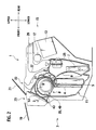
- Fig. 2 shows the vehicular air conditioner 1.
- the vehicular air conditioner 1 includes a blower motor unit 3, an air filter 4, a cooling heat exchanger 5, a heating heat exchanger 7, an air mix door 9 for adjusting a mixture rate of air from the cooling heat exchanger 5 and the heating heat exchanger 7, and a main casing 11 (an HVAC case) for accommodating these elements.
- the vehicular air conditioner 1 is disposed in front of an instrument panel 15 on which an audio device 13 and so on are mounted and a cross-car beam 17 which is disposed in the instrument panel 15 in a vehicle widthwise direction.
- the blower motor unit 3 is disposed in a forward and vertical upper portionin the vehicular air conditioner 1.
- blower motor unit 3 If the blower motor unit 3 is operated, fresh air is sucked from an fresh air intake port 23 provided between a hood 19 and a front window 21, the fresh air passes through an air filter 4, and the fresh air is cooled by the cooling heat exchanger 5 or heated by the heating heat exchanger 7.
- the mixture rate of the cooled or heated fresh air is adjusted by the air mix door 9, and is sent into a passenger compartment from a foot vent 25 or from a vent grill 29 through a duct 27.
- the air is ventilated from a defroster nozzle 33 through the duct 31 to the inner surface of the front window 21.
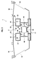
- the blower motor unit 3 includes an electric motor 35 which can output power at both ends of a rotation shaft, a pair of fans 40, 41 mounted on a output shaft 37, 39, and scrolls (fan cases) 43, 44 which accommodates the fans 40, 41 respectively.
- the electric motor 35 is mounted on a central case 45 provided at the center of the scrolls 43, 44 via a soft mount member 47 that absorbs vibration.
- the scrolls 43, 44 respectively includes center scrolls 49, 50 connected to the central case 45, and scroll-side sidewalls 51, 52 respectively fixed to the scrolls 49, 50 as shown in Figs. 6 and 7 .
- a gap 53 of width D is provided between outer peripheries of the scrolls 43, 44 and an inner periphery of the main casing 11.
- the gap 53 functions as an air passage.
- Intake ports 62, 64 which respectively open on the center scrolls 49, 50 are communicated with air intake cases 55, 56 via the gap 53 like intake ports 46, 48 of the scrolls 43, 44.
- air intake cases (side members) 55, 56 are mounted on both sides of the blower motor unit 3 in the widthwise direction.
- the air intake cases 55, 56 are respectively provided with air intake doors 57, 58.
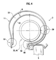
- slide-guiding holders 59, 60, 61 are provided between the scrolls 43, 44 of the blower motor unit 3 and the main casing 11.
- the slide-guiding holders 59, 60, 61 is slidable in the widthwise direction using the flanges and grooves of their own.
- the blower motor unit 3 is movably assembled in the widthwise direction with respect to the main casing 11 by these slide-guiding holders 59, 60, 61.
- the flanges and grooves of the slide-guiding holders 59, 60, 61 are labyrinth grooves, and there is an effect that air discharged from a discharge port 54 of the blower motor unit 3 to the main casing 11 is prevented from reversely flowing toward the gap 53.
- blower motor unit 3 Since the blower motor unit 3 is movably assembled in the vehicle widthwise direction in this manner, the blower motor unit 3 can be detached from the main casing 11 by a method I shown in Fig. 6 or a method II shown in Fig. 7 .
- the blower motor unit 3 can be easily detached from the main casing 11 by moving the blower motor unit 3 in the vehicle widthwise direction. As a result, when the blower motor unit 3 is to be detached, it is unnecessary to detach the whole vehicular air conditioner 1 from the vehicle or to disassemble the vehicular air conditioner 1 entirely. Thus, the detaching cost is largely reduced.
- the gap D is provided between the scrolls 43, 44 and the main casing 11, it becomes easy to pull out the blower motor unit 3. Since the gap D functions as the air passage, the efficiency of the blower motor unit 3 is enhanced.
- the attaching and detaching operations are facilitated.
- a part mounted within the instrument panel 15 of the vehicle is provided with the hooks 63 and 65, there are effects that even when both hands cannot effectively use at the time of the pulling out operation, a pull-out location for easily detaching can be indicated and a pulling force can be easily applied to a part which is to be pulled out.
- the air leakage is reduced and efficiency is enhanced due to the labyrinth seal functions of the slide-guiding holders 59, 60, 61.
- Fig. 5 shows an example in which the blower motor unit 3 is provide with the hooks 63, 65 and the slide-guiding holders 59, 60, 61. While air leakage between the blower unit and the main casing 11 is reduced by the slide-guiding holders, the sliding friction is increased on the contrary.
- the hooks 63, 65 are provided on the side surface of the blower motor unit 3 in a pulling out direction. At the time of pulling out operation, a hand, a finger or a tool can be easily hooked and a force is effectively applied. Since the hooks 63, 65 are provided near the slide-guiding holders, the pulling out force is applied to the area where the sliding friction is occurred.
- Such hooks can be provided on the air intake cases (side members) 55, 56. With this configuration, the air intake cases (side members) 55, 56 can easily slide. Both of or one of the air intake cases (side members) 55, 56 can be provided with the hook.
- a different type blower (fan(s) and fan case(s)) from that of the embodiment can be used arbitrarily.
- the blower motor unit 3 is detached from the left side, but in the vehicular air conditioner of the present invention, the right air intake case 56 can be removed and the blower motor unit 3 can be detached from the right side if necessary.
- the blower motor unit can be moved in the widthwise direction, the blower motor unit can be easily detached from a main casing, thereby largely reducing the detaching cost.
Landscapes
- Physics & Mathematics (AREA)
- Thermal Sciences (AREA)
- Engineering & Computer Science (AREA)
- Mechanical Engineering (AREA)
- Air-Conditioning For Vehicles (AREA)
- Structures Of Non-Positive Displacement Pumps (AREA)
Abstract
A twin-type blower motor unit that drives fans provided on both sides in an axial direction by an electric motor is disposed on an upper portion of a main casing in the vertical direction. The blower motor unit is movably assembled in the vehicle widthwise direction with respect to the main casing.
Description
- The present invention relates to a vehicular air conditioner.
- As a required air volume is increased and a required size is reduced, there has been proposed a twin-type blower that drives two fans using one electric motor as a blower used for a vehicular air conditioner instead of a blower (one-side blower type) that drives one fan using one electric motor.
- It is preferable that a blower, a rotating device, has a structure that can be attached and detached easily for maintenance, inspection, and repair. In the case of the one-side blower, for example, if a vehicular air conditioner which has a blower at its lower portion in the vertical direction is disposed on a passenger side, the blower can be easily attached and detached. In the case of a vehicular air conditioner which has a blower at its upper portion and tends to be well-used in recent years, the blower can be easily attached and detached through a glove box.
-
Fig. 1 shows a vehicular blower 201 (a twin-type blower) described inPatent Document 1. In thevehicular blower 201, abiaxial motor 203 and a pair offans case 209 comprises asuction unit 211 and adischarge unit 213 fixed to thesuction unit 211 such that thedischarge unit 213 penetrates therein.
Patent Document 1:Japanese Patent Application Laid-open No. H7-144528 - However, in the case of a structure of the
vehicular blower 201, in order to remove thebiaxial motor 203 and thefans - The present invention has been achieved in view of the problem of the conventional technique, and it is an object of the present invention to provide a vehicular air conditioner to which a blower motor unit can be easily attached and form which it can be detached without removing or disassembling the air conditioner from the vehicle entirely.
- The vehicular air conditioner of the present invention for achieving the above object comprises a twin-type blower motor unit disposed in an upper portion of a main casing (in the vertical direction). The blower motor unit includes a pair of fans disposed on both sides of an electric motor in its axial direction and driven by an electric motor. The blower motor unit is movably assembled in a vehicle widthwise direction with respect to the main casing.
- In the vehicular air conditioner of the present invention having such a structure, the blower motor unit can be easily detached from the main casing only by moving the blower motor unit in the vehicle widthwise direction. Since it is unnecessary to remove the air conditioner from the vehicle entirely or disassemble the air conditioner when removing the blower motor unit, the detaching cost is largely reduced.
- In the case of a structure where a gap is provided between fan cases and the main casing of the blower motor unit, the pulling out operation of the blower motor unit becomes easy, the gap functions as an air passage (an air path), and the efficiency of the blower motor unit is enhanced correspondingly.
- In the case of a structure where a hook is provided on a side member of the main casing and/or the blower motor unit, it becomes easy to attach and detach the blower motor unit or the side member.
- In the case of a structure where the blower motor unit is movably assembled in the vehicle widthwise direction with respect to the main casing by a slide-guiding holder that is slidable in the vehicle widthwise direction, and flanges and grooves of the slide-guiding holder function as a seal mechanism, it is easy to remove the blower motor unit as described above, air-leak is reduced by the seal function of the flanges and grooves, and the efficiency of the blower motor unit is enhanced correspondingly.
-
-
Fig. 1 is a sectional view of a conventional vehicular air conditioner; -
Fig. 2 is a diagram showing a vehicular air conditioner and its mounting direction according to an embodiment of the present invention; -
Fig. 3 is a sectional view taken along the line 3-3 inFig. 2 ; -
Fig. 4 is an enlarged view of a portion B inFig. 2 ; -
Fig. 5 is a perspective view of a blower motor unit; -
Fig. 6 is a diagram showing a removing method I of the blower motor unit; and -
Fig. 7 is a diagram showing a removing method II of the blower motor unit. - A
vehicular air conditioner 1 according to an embodiment of the present invention will be explained below with reference toFig. 2 to Fig. 7 . -
Fig. 2 shows thevehicular air conditioner 1. Thevehicular air conditioner 1 includes ablower motor unit 3, an air filter 4, acooling heat exchanger 5, a heating heat exchanger 7, an air mix door 9 for adjusting a mixture rate of air from thecooling heat exchanger 5 and the heating heat exchanger 7, and a main casing 11 (an HVAC case) for accommodating these elements. Thevehicular air conditioner 1 is disposed in front of aninstrument panel 15 on which anaudio device 13 and so on are mounted and across-car beam 17 which is disposed in theinstrument panel 15 in a vehicle widthwise direction. Theblower motor unit 3 is disposed in a forward and vertical upper portionin thevehicular air conditioner 1. - If the
blower motor unit 3 is operated, fresh air is sucked from an freshair intake port 23 provided between ahood 19 and afront window 21, the fresh air passes through an air filter 4, and the fresh air is cooled by thecooling heat exchanger 5 or heated by the heating heat exchanger 7. The mixture rate of the cooled or heated fresh air is adjusted by the air mix door 9, and is sent into a passenger compartment from afoot vent 25 or from avent grill 29 through aduct 27. The air is ventilated from adefroster nozzle 33 through theduct 31 to the inner surface of thefront window 21. - As shown in
Fig. 3 , theblower motor unit 3 includes anelectric motor 35 which can output power at both ends of a rotation shaft, a pair offans output shaft fans electric motor 35 is mounted on acentral case 45 provided at the center of thescrolls soft mount member 47 that absorbs vibration. Thescrolls center scrolls central case 45, and scroll-side sidewalls scrolls Figs. 6 and7 . - In a state where the
electric motor 35 is mounted on thecentral case 45, agap 53 of width D is provided between outer peripheries of thescrolls main casing 11. Thegap 53 functions as an air passage.Intake ports center scrolls air intake cases gap 53 likeintake ports scrolls - As shown in
Figs. 3 ,6 , and7 , air intake cases (side members) 55, 56 are mounted on both sides of theblower motor unit 3 in the widthwise direction. Theair intake cases air intake doors - As shown in
Fig. 4 , slide-guidingholders scrolls blower motor unit 3 and themain casing 11. The slide-guidingholders blower motor unit 3 is movably assembled in the widthwise direction with respect to themain casing 11 by these slide-guidingholders holders discharge port 54 of theblower motor unit 3 to themain casing 11 is prevented from reversely flowing toward thegap 53. - Since the
blower motor unit 3 is movably assembled in the vehicle widthwise direction in this manner, theblower motor unit 3 can be detached from themain casing 11 by a method I shown inFig. 6 or a method II shown inFig. 7 . - According to the method I shown in
Fig. 6 , - (1) the left
air intake case 55 is detached from themain casing 11, - (2) the scroll-
side sidewall 51 of theleft scroll 43 is detached from thecenter scroll 49, and - (3) the remaining blower motor unit 3 (without the left scroll-side sidewall 51) is detached from the
main casing 11 by use of the slide-guidingholders - According to the method II shown in
Fig. 7 , - (1) the left
air intake case 55 is detached from themain casing 11, and - (2) the whole
blower motor unit 3 is detached from themain casing 11 by use of the slide-guidingholders - According to the
vehicular air conditioner 1 having the structure described above, theblower motor unit 3 can be easily detached from themain casing 11 by moving theblower motor unit 3 in the vehicle widthwise direction. As a result, when theblower motor unit 3 is to be detached, it is unnecessary to detach the wholevehicular air conditioner 1 from the vehicle or to disassemble thevehicular air conditioner 1 entirely. Thus, the detaching cost is largely reduced. - Since the gap D is provided between the
scrolls main casing 11, it becomes easy to pull out theblower motor unit 3. Since the gap D functions as the air passage, the efficiency of theblower motor unit 3 is enhanced. - If the
air intake cases blower motor unit 3 is provided withhooks instrument panel 15 of the vehicle is provided with thehooks - The air leakage is reduced and efficiency is enhanced due to the labyrinth seal functions of the slide-guiding
holders -
Fig. 5 shows an example in which theblower motor unit 3 is provide with thehooks holders main casing 11 is reduced by the slide-guiding holders, the sliding friction is increased on the contrary. Here, in order to facilitate the sliding at the time of the attaching and detaching operations, thehooks blower motor unit 3 in a pulling out direction. At the time of pulling out operation, a hand, a finger or a tool can be easily hooked and a force is effectively applied. Since thehooks - According to the vehicular air conditioner of the present invention, a different type blower (fan(s) and fan case(s)) from that of the embodiment can be used arbitrarily.
- In the above embodiment, the
blower motor unit 3 is detached from the left side, but in the vehicular air conditioner of the present invention, the rightair intake case 56 can be removed and theblower motor unit 3 can be detached from the right side if necessary. - In the vehicular air conditioner of the present invention, since a blower motor unit can be moved in the widthwise direction, the blower motor unit can be easily detached from a main casing, thereby largely reducing the detaching cost.
Claims (4)
- A vehicular air conditioner comprising:a twin-type blower motor unit including a pair of fans that are disposed on both sides of an electric motor in its axial direction and driven by the electric motor; anda main casing,wherein the blower motor unit is disposed in an upper portion of the main casing and movably assembled in a vehicle widthwise direction with respect to the main casing.
- The vehicular air conditioner according to claim 1,
wherein the blower motor unit includes the electric motor, the pair of fans, and fan cases for accommodating the fans, and
a gap that functions as an air passage is provided between the fan cases and the main casing. - The vehicular air conditioner according to claim 2,
wherein the main casing includes a side member disposed in the vehicle widthwise direction of the blower motor unit, and
a hook is provided on the side member and/or the fan case. - The vehicular air conditioner according to claim 1, further comprising a slide-guiding holder that is provided between the blower motor unit and the main casing and slidable in the vehicle widthwise direction,
wherein the blower motor unit is movably assembled in the vehicle widthwise direction with respect to the main casing by the slide-guiding holder, and
the slide-guiding holder includes flanges and grooves constituting a seal mechanism.
Applications Claiming Priority (2)
| Application Number | Priority Date | Filing Date | Title |
|---|---|---|---|
| JP2005225156 | 2005-08-03 | ||
| PCT/JP2006/314856 WO2007015413A1 (en) | 2005-08-03 | 2006-07-27 | Air conditioner for automobile |
Publications (1)
| Publication Number | Publication Date |
|---|---|
| EP1911615A1 true EP1911615A1 (en) | 2008-04-16 |
Family
ID=37708693
Family Applications (1)
| Application Number | Title | Priority Date | Filing Date |
|---|---|---|---|
| EP06781767A Withdrawn EP1911615A1 (en) | 2005-08-03 | 2006-07-27 | Air conditioner for automobile |
Country Status (5)
| Country | Link |
|---|---|
| US (1) | US20080115518A1 (en) |
| EP (1) | EP1911615A1 (en) |
| JP (1) | JPWO2007015413A1 (en) |
| CN (1) | CN100509458C (en) |
| WO (1) | WO2007015413A1 (en) |
Cited By (2)
| Publication number | Priority date | Publication date | Assignee | Title |
|---|---|---|---|---|
| DE102009037920A1 (en) * | 2009-08-19 | 2011-02-24 | Behr Gmbh & Co. Kg | Motor vehicle air conditioning system has outer housing, inner housing arranged within outer housing and turbo machine driven by motor, where turbo machine is arranged within inner housing |
| DE102024112316A1 (en) * | 2024-05-02 | 2025-11-06 | Bayerische Motoren Werke Aktiengesellschaft | Air conditioning system for the interior of a motor vehicle, as well as motor vehicle with air conditioning system |
Families Citing this family (6)
| Publication number | Priority date | Publication date | Assignee | Title |
|---|---|---|---|---|
| JP4396738B2 (en) * | 2007-07-23 | 2010-01-13 | 株式会社デンソー | Air conditioner |
| JP4513835B2 (en) | 2007-07-23 | 2010-07-28 | 株式会社デンソー | Air conditioner |
| JP5180702B2 (en) * | 2008-06-25 | 2013-04-10 | カルソニックカンセイ株式会社 | Vehicle air conditioner and work method |
| JP5191833B2 (en) * | 2008-08-08 | 2013-05-08 | カルソニックカンセイ株式会社 | Vehicle air conditioner and blower unit replacement work method |
| JP6384599B2 (en) * | 2015-04-24 | 2018-09-05 | 株式会社デンソー | Air conditioner for vehicles |
| KR102292952B1 (en) * | 2019-11-21 | 2021-08-23 | 덴소코리아 주식회사 | Blowing apparatus of air conditioner for vehicle with two layer air flow |
Family Cites Families (14)
| Publication number | Priority date | Publication date | Assignee | Title |
|---|---|---|---|---|
| US3105431A (en) * | 1961-04-06 | 1963-10-01 | Ford Motor Co | Motor vehicle construction |
| US3977467A (en) * | 1973-05-18 | 1976-08-31 | Northrup Jr Leonard L | Air conditioning module |
| US4023350A (en) * | 1975-11-10 | 1977-05-17 | United Technologies Corporation | Exhaust case for a turbine machine |
| JPS5727611Y2 (en) * | 1978-03-29 | 1982-06-16 | ||
| US4450755A (en) * | 1982-02-04 | 1984-05-29 | Dynaforce Corporation | Air blower arrangement for producing air screen and related method |
| US5403163A (en) * | 1990-08-20 | 1995-04-04 | Molded Products Company | Motor mount for blower housing |
| JPH10264639A (en) * | 1997-03-25 | 1998-10-06 | Sanden Corp | Air conditioner |
| JP4478904B2 (en) * | 1999-12-03 | 2010-06-09 | 株式会社ヴァレオサーマルシステムズ | Automotive air conditioner |
| US6471137B1 (en) * | 2000-04-12 | 2002-10-29 | Thomas Built Buses, Inc. | Externally accessible climate control system for passenger coaches |
| JP4098495B2 (en) * | 2001-06-22 | 2008-06-11 | カルソニックカンセイ株式会社 | Air conditioner for vehicles |
| CN2511517Y (en) * | 2001-12-24 | 2002-09-18 | 上海德尔福汽车空调系统有限公司 | Unitary temperature adjusting air conditioner for automobile |
| US6637232B1 (en) * | 2002-07-24 | 2003-10-28 | .Pef Industries, Inc. | Unit ventilator |
| US6896478B2 (en) * | 2002-12-16 | 2005-05-24 | Visteon Global Technologies, Inc. | Dual fan blower with axial expansion |
| KR101152018B1 (en) * | 2005-05-20 | 2012-06-08 | 한라공조주식회사 | Center mounting type air conditioner for vehicle |
-
2006
- 2006-07-27 US US11/662,180 patent/US20080115518A1/en not_active Abandoned
- 2006-07-27 CN CNB2006800011921A patent/CN100509458C/en not_active Expired - Fee Related
- 2006-07-27 WO PCT/JP2006/314856 patent/WO2007015413A1/en not_active Ceased
- 2006-07-27 EP EP06781767A patent/EP1911615A1/en not_active Withdrawn
- 2006-07-27 JP JP2007529226A patent/JPWO2007015413A1/en active Pending
Non-Patent Citations (1)
| Title |
|---|
| See references of WO2007015413A1 * |
Cited By (2)
| Publication number | Priority date | Publication date | Assignee | Title |
|---|---|---|---|---|
| DE102009037920A1 (en) * | 2009-08-19 | 2011-02-24 | Behr Gmbh & Co. Kg | Motor vehicle air conditioning system has outer housing, inner housing arranged within outer housing and turbo machine driven by motor, where turbo machine is arranged within inner housing |
| DE102024112316A1 (en) * | 2024-05-02 | 2025-11-06 | Bayerische Motoren Werke Aktiengesellschaft | Air conditioning system for the interior of a motor vehicle, as well as motor vehicle with air conditioning system |
Also Published As
| Publication number | Publication date |
|---|---|
| CN100509458C (en) | 2009-07-08 |
| WO2007015413A1 (en) | 2007-02-08 |
| JPWO2007015413A1 (en) | 2009-02-19 |
| CN101061005A (en) | 2007-10-24 |
| US20080115518A1 (en) | 2008-05-22 |
Similar Documents
| Publication | Publication Date | Title |
|---|---|---|
| JP5482720B2 (en) | Air conditioner for vehicles | |
| CA2512527A1 (en) | Motor cooling structure for electric vehicle | |
| EP1911615A1 (en) | Air conditioner for automobile | |
| CN111033144B (en) | Indoor unit of air conditioner | |
| US20180251012A1 (en) | Vehicular defroster duct structure | |
| JP4103570B2 (en) | Air conditioning unit for vehicle air conditioner | |
| CN100439802C (en) | Air conditioner | |
| EP1967395A1 (en) | Air conditioner | |
| CN104228518A (en) | Automobile air conditioner | |
| KR100964362B1 (en) | Air conditioner | |
| CN118215590A (en) | Vehicle air conditioning device | |
| KR100244205B1 (en) | device for coupling air filter in air conditioner | |
| JPH09240255A (en) | Air conditioner for automobile | |
| JP2004138309A (en) | Air conditioner | |
| JP6193447B2 (en) | Combine | |
| JP5950504B2 (en) | Combine | |
| KR100452610B1 (en) | Heater-vent-air conditioning unit for vehicle | |
| JP4735360B2 (en) | Vehicle cooling system | |
| JP4971628B2 (en) | Blower mounting structure | |
| JP2005306262A (en) | Air-conditioning apparatus for automobile | |
| KR19980027560U (en) | Roof Mount Air Conditioner | |
| JP2006194508A (en) | Separate air conditioner | |
| JP2002061942A (en) | Air conditioner | |
| KR20030042711A (en) | Method and apparatus for control front grill of airconditioner | |
| KR0121879B1 (en) | Air conditioning system of an automobile |
Legal Events
| Date | Code | Title | Description |
|---|---|---|---|
| PUAI | Public reference made under article 153(3) epc to a published international application that has entered the european phase |
Free format text: ORIGINAL CODE: 0009012 |
|
| 17P | Request for examination filed |
Effective date: 20070307 |
|
| AK | Designated contracting states |
Kind code of ref document: A1 Designated state(s): DE FR GB |
|
| DAX | Request for extension of the european patent (deleted) | ||
| RBV | Designated contracting states (corrected) |
Designated state(s): DE FR GB |
|
| STAA | Information on the status of an ep patent application or granted ep patent |
Free format text: STATUS: THE APPLICATION HAS BEEN WITHDRAWN |
|
| 18W | Application withdrawn |
Effective date: 20090804 |