EP1911344A2 - Structure for attaching chip receiver to hedge trimmer - Google Patents
Structure for attaching chip receiver to hedge trimmer Download PDFInfo
- Publication number
- EP1911344A2 EP1911344A2 EP07019724A EP07019724A EP1911344A2 EP 1911344 A2 EP1911344 A2 EP 1911344A2 EP 07019724 A EP07019724 A EP 07019724A EP 07019724 A EP07019724 A EP 07019724A EP 1911344 A2 EP1911344 A2 EP 1911344A2
- Authority
- EP
- European Patent Office
- Prior art keywords
- clip
- retaining board
- chip receiver
- clamping members
- distance
- Prior art date
- Legal status (The legal status is an assumption and is not a legal conclusion. Google has not performed a legal analysis and makes no representation as to the accuracy of the status listed.)
- Granted
Links
Images




Classifications
-
- A—HUMAN NECESSITIES
- A01—AGRICULTURE; FORESTRY; ANIMAL HUSBANDRY; HUNTING; TRAPPING; FISHING
- A01G—HORTICULTURE; CULTIVATION OF VEGETABLES, FLOWERS, RICE, FRUIT, VINES, HOPS OR SEAWEED; FORESTRY; WATERING
- A01G3/00—Cutting implements specially adapted for horticultural purposes; Delimbing standing trees
- A01G3/04—Apparatus for trimming hedges, e.g. hedge shears
- A01G3/047—Apparatus for trimming hedges, e.g. hedge shears portable
- A01G3/053—Apparatus for trimming hedges, e.g. hedge shears portable motor-driven
-
- A—HUMAN NECESSITIES
- A01—AGRICULTURE; FORESTRY; ANIMAL HUSBANDRY; HUNTING; TRAPPING; FISHING
- A01G—HORTICULTURE; CULTIVATION OF VEGETABLES, FLOWERS, RICE, FRUIT, VINES, HOPS OR SEAWEED; FORESTRY; WATERING
- A01G3/00—Cutting implements specially adapted for horticultural purposes; Delimbing standing trees
- A01G3/02—Secateurs; Flower or fruit shears
- A01G2003/023—Secateurs; Flower or fruit shears with means for grasping or collecting the cut objects
Definitions
- the present invention relates to a structure for attaching a chip receiver to a hedge trimmer.
- a retaining board, and a blade section having a pair of movable blades which reciprocate back and forth below the retaining board are provided in a manner of projecting forward from a main body, so that twigs and leaves can be cropped by reciprocating the movable blades in opposite directions to each other.
- 2003-111520A discloses a structure for enabling the chip receiver to be easily attached, by inserting a fixing screw which is provided so as to extend upward from the retaining board into a fixing slot hole which is provided in the chip receiver, and by screwing a knob nut over the fixing screw.
- a structure for mounting a chip receiver to a blade section extended forward from a main body of a hedge trimmer comprising:
- the clip may include a pair of clamping members adapted to detachably clamp the retaining board. At least one of the clamping members may be elastically deformable to vary a distance therebetween.
- the clip may have a part adapted to be actuated by, a human finger to elastically deform the at least one of the clamping members.
- Side faces of the retaining board may be provided with a pair of grooves which extend in a longitudinal direction thereof and which are adapted to engage with the clamping members.
- the chip receiver can be attached to or detached from the retaining board by the simple operation of the clip, it is excellent in usability. In addition, there is no anxiety of losing components. Especially, since the clip is mounted on the retaining board by clamping the side faces of the retaining board, the chip receiver can be attached on the retaining board irrespective of the peripheral structure of the blade section. Thus, the chip receiver can be mounted with respect to various types of hedge trimmers.
- At least one of the retaining board and the clamping members may be provided with at least one chamfered face adapted to assist an elastic deformation of the at least one of the clamping members in such a direction that the distance is enlarged.
- At least one metal wire having a plurality of bent parts may constitute the clamping members.
- the clip can be prepared at low cost.
- the structure may further comprise a lever, engaged with one of the bent parts and adapted to be operated to elastically deform the one of the clamping members to vary the distance.
- the elastic deformation of the clamping member can be easily performed with less force.
- the lever may be movable between a first position and a second position, and is adapted to be statically placed in either the first position or the second position.
- the distance between the clamping members may be a first distance adapted to clamp the retaining board when the lever is placed in the first position.
- the distance between the clamping members may be a second distance allowing an attachment or detachment of the clip with respect to the retaining board.
- a hedge trimmer 1 includes a main body 2 in which a motor and a crank mechanism for converting rotation of the motor to a linear movement, which are not shown, are incorporated, and a blade section 3 which is projected forward (to a left side in Fig. 1) from the main body 2 and adapted to be moved by the crank mechanism.
- This blade section 3 includes band-shaped upper and lower retaining boards 4, and two movable blades 5 which are positioned between the two retaining boards 4 and provided with edges 6 on both side edges thereof in a staggered manner.
- the movable blades 5 are moved back and forth in opposite directions to each other by the crank mechanism, it is possible to crop twigs and leaves with the edges 6.
- Denoted with numeral 7 is a main handle provided with a trigger switch 8.
- Denoted with numeral 9 is an auxiliary handle which is projected diagonally forward from the main body 2.
- Denoted with numeral 10 is a protector.
- the chip receiver 11 includes a plate-shaped attaching part 12 which is attached to an upper face of the upper retaining board 4 in the blade section 3 of the hedge trimmer 1, and a bowl-shaped receiving part 13 which is continued from one side edge of the attaching part 12.
- the receiving part 13 is formed in a deep bottomed shape having a bottom positioned lower than the attaching part 12, so that the twigs and leaves which have been cropped may not overflow and catchability may be enhanced.
- a wall 14 which is continued from front and back ends of the attaching part 12 is uprightly formed on an outer periphery of the receiving part 13.
- a lower face of the receiving part 13 is set so as not to be lower than a lower face of the blade section 3, so that the receiving part 13 may not disturb cropping work, when the chip receiver 11 is attached to the blade section 3.
- the attaching part 12 is provided with a plurality of relief slots 16 for avoiding interferences with the fixing screws 15 of the blade section 3, extending in parallel to a longitudinal direction of the blade section 3.
- a pair of grooves 17 are formed at two positions between the relief slots 16, so as to extend from the side edge of the attaching part 12 on an opposite side to the receiving part 13 substantially at the right angle with the attaching part 12, and clips 18 are respectively provided inside the grooves 17.
- Each of the clips 18 is a molded product of synthetic resin having a pair of locking pieces 21 which are connected by elastic pieces 20, on both sides of a center plate 19.
- the clip 18 is contained in a holder 22 which is formed so as to project upward by connecting front and back edges of the groove 17, and has an inverted U-shape in cross section.
- the center plate 19 is fixed with a screw 24 to a boss 23 which is projected downward from a center of an inner face of the holder 22, whereby the clip 18 is held in a state where the locking pieces 21 are exposed from both sides of the holder 22.
- the clip 18 is further provided with locking hooks 25 at lower ends of the locking pieces 21 on their faces opposed to each other.
- the locking hooks 25 are adapted to be engaged with locking grooves 26 which are formed on both side faces of the upper retaining board 4 of the hedge trimmer 1 along an entire length thereof.
- the clip 18 In a state where the locking hooks 25 are not engaged with the locking grooves 26, the clip 18 is maintained in a state in which a distance between the locking hooks 25 is made rather smaller than a width of the retaining board 4 by the elastic pieces 20.
- the locking pieces 21 are respectively provided, on their lower end faces, with chamfered parts 27 which are inclined upward in a direction toward distal ends of the locking hooks 25.
- chamfered parts 28 for guiding the locking pieces 21 to spread are also provided in corner parts of the retaining board 4.
- the locking pieces 21 of the front and rear clips 18 are pushed downward in a state where the lower ends of the locking pieces 21 are respectively butted against the right and left side edges of the retaining board 4. Then, the lower ends of the locking pieces 21 spread by the guides of the chamfered parts 27, 28 thereby to allow intrusion of the retaining board 4 between the locking hooks 25.
- the locking hooks 25 arrive the locking grooves 26, the locking hooks 25 are urged close to each other and engaged with the locking grooves 26, as shown in Fig. 3.
- the chip receiver 11 can be attached to the retaining board 4 in such a manner that the retaining board 4 is clamped with the front and rear clips 18. It is to be noted that the chip receiver 11 can be attached in a reverse direction as shown in Fig. 4, because of the structure of clamping the retaining board 4 in this manner.
- the upper ends of the locking pieces 21 of the clip 18 are nipped with fingers from both sides. Then, the lower ends of the locking pieces 21 are spread allowing the locking hooks 25 to be disengaged from the locking grooves 26, whereby the chip receiver 11 can be detached.
- the locking grooves 26 are respectively formed on the right and left side faces of the retaining board 4, while the clips 18 of which the lower ends can be elastically engaged with the locking grooves 26 of the retaining board 4 and can be spread as desired are provided on the attaching part 12 of the chip receiver 11, whereby the chip receiver 11 can be attached to the blade section 3 by clamping the retaining board 4 with the clips 18. Therefore, the chip receiver 11 can be attached or detached by simple operation of the clips 18, and it is possible to provide the attaching structure which is excellent in usability. Of course, there is no anxiety of losing components. Moreover, because the retaining board 4 is clamped at the side faces, it is possible to attach the chip receiver irrespective of a fixing structure of the blade section 3, and this attaching structure can be employed in the hedge trimmer of different types.
- the chamfered parts 27, 28 are provided on the corner parts of the retaining board 4 and the lower ends of the clip 18, for the purpose of guiding the lower ends of the clip 18 so as to spread, when the corner parts of the retaining board 4 and the lower ends of the clip 18 come into contact with each other. Therefore, on occasion of attaching the chip receiver 11, there is no necessity of operating the clip 18 to spread, and the chip receiver 11 can be attached with a single operation. As a results, attaching operation is further simplified, and usability is enhanced.
- both of the locking pieces of the clip need not be elastically engaged, but one of the locking pieces may be fixed to the attaching part of the chip receiver, while only the other locking piece may be imparted with elasticity to clamp the retaining board.
- the chamfered parts of the retaining board can be omitted, because it is possible to guide the spread only with the chamfered parts of the clip.
- the chamfered parts may be provided only on the retaining board, and the chamfered parts on the clip may be omitted.
- the structure can be appropriately modified in design, for example, by increasing the number of the clips, by providing intermittent recesses instead of the locking grooves of the retaining board, and so on.
- the clip is not limited to the molded product of synthetic resin as in the first embodiment, but may be formed of a leaf spring or wire member of metal.
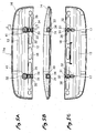
- Figs. 5A to 5C show a chip receiver 11 a which is provided with a clip 30 formed of wire member, in a plan view, in a front view, and in a bottom view, from above.
- the clip 30 in this embodiment includes a first hook 31 and a second hook 32 which are formed by folding a piece of wire member made of steel.
- the two hooks 31, 32 are respectively held on a first holder 34 and a second holder 35 which are provided between partition walls 33 uprightly provided on a circumferential edge of the groove 17.
- the first hook 31 is formed by folding a piece of wire member to form a first U-shape portion 37 at its center, and by extending both side portions in parallel.
- the two portions in parallel are folded in a quadrangle shape so as to extend along an outer face of the first holder 34 which has an L-shape in cross section, and a pair of free ends 36 in an upper position are inserted between the first and second holders 34, 35 to be hung downward, while the first U-shape portion 37 at the center in a lower position is projected toward the receiving part 13, below the first holder 34, thereby to serve as a locking hook.
- the second hook 32 is formed by folding a piece of wire member to form a second U-shape portion 38 at its lower end, which is opposed to the first U-shape portion 37 of the first hook 31.
- the second hook 32 is not symmetrical in the front-rear direction unlike the first hook 31, but one side edge is inclined upward so as to become highest at the center in the left-right direction, and a pair of free ends 39 are folded in parallel in the longitudinal direction, at a higher position than the other edge.
- the second hook 32 When the upper end of the second hook 32 is lifted from this state with fingers, the second hook 32 is rotated so that the second U-shape portion 38 can be separated from the first U-shape portion 37 thereby to enlarge a distance between them.
- the hook 32 When the fingers are detached from the upper end, the hook 32 is returned to the original position by elasticity.
- the upper end of the second hook 32 is lifted with fingers, whereby the second U-shape portion 38 moves away from the first U-shape portion 37 of the first hook 31 and the distance between them becomes larger than the width of the retaining board.
- the attaching part 12 is set on the retaining board 4, while the first U-shape portion 37 of the first hook 31 in this state is engaged with one of the locking grooves 26, and the fingers are detached from the upper end of the second hook 32, whereby the second U-shape portion 38 of the second hook 32 is elastically engaged with the other locking groove 26 thereby to clamp the retaining board 4. In this manner, attaching of the chip receiver 11 a can be performed.
- the chip receiver 11a In order to detach the chip receiver 11a, the upper end of the second hook 32 is lifted with fingers to disengage the second U-shape portion 38 from the locking groove 26, and thereafter, the chip receiver 11 a may be inclined in a manner of lifting the relevant side, whereby the first U-shape portion 37 of the first hook 31 can be disengaged from the other locking groove 26.
- the chip receiver 11 a in this embodiment it is possible to attach the chip receiver 11 a to the blade section 3 by clamping the retaining board 4 with the clip 30. Therefore, the chip receiver 11a can be attached or detached by simple operation of the clip 30, and usability is enhanced. Moreover, there occurs no anxiety of losing components. Further, because the retaining board 4 is clamped at the side faces, it is possible to attach the chip receiver 11a irrespective of the fixing structure of the blade section 3, and this attaching structure can be employed in the hedge trimmer of different types.
- the clip 30 can be easily formed of steel wire, and because the upper end of the second hook 32 is protected by the end part 41 of the partition walls 33, there is no anxiety of accidental drop of the clip.
- the end part 41 is formed in a round shape and larger than the width of the groove 17, which facilitates operation of the upper end of the second hook 32 with the fingers.
- the first hook 31 is positioned on the side edge of the attaching part 12, while the second hook 32 is positioned at a side adjacent to the receiving part 13. However, their positions may be exchanged. Moreover, although only the second hook 32 is elastically engaged with the locking groove 26, the first hook 31 may be also imparted with elasticity having the same structure, so that the two hooks may be nipped with fingers to be spread.
- the chip receiver In case of detaching the chip receiver, in a reverse order, the chip receiver is pulled to disengage the first U-shape portion 43 from the locking groove 26, and the chip receiver is inclined by lifting the relevant side upward to release the pulled state, whereby the second U-shape portion 44 can be disengaged from the other locking groove 26.
- the chip receiver can be attached to the blade section 3 by clamping the retaining board 4 with the clip 42, and the same effect as in the second embodiment can be obtained.
- this embodiment is more advantageous than the second embodiment in economical point of view, because the clip can be formed of a piece of wire member, and the structure of the positioning part can be made simple.
- a fourth embodiment of the invention will be described with reference to Fig. 9A to 11.
- a pair of a first U-shape portion 51 and a second U-shape portion 52 to be engaged with the locking grooves 26 of the retaining board 4 are formed of a piece of wire member, in the same manner as in the third embodiment.
- a middle portion of the clip 50 is held between projections 54 formed between opposed faces of a pair of holding walls 53 which are provided at a determined interval in the longitudinal direction of the chip receiver 11, and the first U-shape portion 51 is held inside a connecting wall 5 which is uprightly provided so as to connect end areas of the holding walls 53.
- a base end of an operating lever 57 is pivotally attached so as to rotate, inside the second U-shape portion 52, about pins 56 extending in the longitudinal direction of the retaining board 4.
- a cam part 58 of this base end is formed in a cam shape having a projected end 58a which is projected in a radial direction from a pivot center.
- the projected end 58a is directed diagonally downward so as to protrude from a back face of the chip receiver 11.
- the operating lever 57 is rotated toward the first U-shape portion 51 so as to be erected from the chip receiver 11 (for the purpose of facilitating this erecting operation, the distal end of the operating lever 57 is formed in an L-shape in such a manner that the operating lever 57 is separated from the upper face of the chip receiver 11 toward the distal end). Then, the projected end 58a of the cam part 58 is rotated while pushing up the clip 50 from inside, against elastic force of the clip 50 in rightward rotation as shown in Fig. 9B, and pulls the second U-shape portion 52 so as to be flexed as shown by arrows in Figs.
- the operating lever 57 is rotated to the attaching/detaching position in the same manner, to disengage the second U-shape portion 52 from the locking groove 26. Thereafter, the chip receiver 11 is inclined by lifting the relevant side, whereby the first U-shape portion 51 is disengaged from the locking groove 26, and the chip receiver 11 can be detached from the blade section 3.
- the cam part of the operating lever is not limited to the above-mentioned shape, but a specific shape of the operating lever can be appropriately modified in design.
- the operating lever may be formed in a simple plate shape, or pins may be provided integrally on both ends of the cam part, provided that spreading motion of the clip can be realized.
- the operating lever may be provided at a side of the first U-shape portion, or a pair of operating levers may be provided at respective sides of the two U-shape portions, so that the spreading motion of the clip can be obtained by simultaneously nipping a pair of the operating levers to rotate.
Landscapes
- Life Sciences & Earth Sciences (AREA)
- Biodiversity & Conservation Biology (AREA)
- Ecology (AREA)
- Forests & Forestry (AREA)
- Environmental Sciences (AREA)
- Harvester Elements (AREA)
Abstract
Description
- The present invention relates to a structure for attaching a chip receiver to a hedge trimmer.
- In a hedge trimmer, a retaining board, and a blade section having a pair of movable blades which reciprocate back and forth below the retaining board are provided in a manner of projecting forward from a main body, so that twigs and leaves can be cropped by reciprocating the movable blades in opposite directions to each other. When an upper face of the hedge is trimmed with this hedge trimmer, in order that the twigs and leaves which have been cropped can be received and gathered immediately, it is often conducted to attach a chip receiver along the retaining board. As an attaching structure of this chip receiver,
Japanese Patent Publication No. 2003-111520A - However, in the attaching structure of the chip receiver as described above, it is necessary to take trouble to rotate the knob nut every time when the chip receiver is attached or detached. Moreover, there is such anxiety that the knob nut may be lost, after the chip receiver is detached, and there is a problem in usability.
- It is therefore an object of the invention to provide a structure for attaching a chip receiver to a hedge trimmer which is excellent in usability, because attaching and detaching operation of the chip receiver to a blade section of the hedge trimmer can be easily conducted, and there is no anxiety of losing components.
- In order to achieve the above object, according to the invention, there is provided a structure for mounting a chip receiver to a blade section extended forward from a main body of a hedge trimmer, the structure comprising:
- a retaining board, retaining movable blades of the blade section; and
- a clip, provided on the chip receiver and adapted to clamp the retaining board elastically and detachably.
- The clip may include a pair of clamping members adapted to detachably clamp the retaining board. At least one of the clamping members may be elastically deformable to vary a distance therebetween.
- The clip may have a part adapted to be actuated by, a human finger to elastically deform the at least one of the clamping members.
- Side faces of the retaining board may be provided with a pair of grooves which extend in a longitudinal direction thereof and which are adapted to engage with the clamping members.
- With the above configurations, since the chip receiver can be attached to or detached from the retaining board by the simple operation of the clip, it is excellent in usability. In addition, there is no anxiety of losing components. Especially, since the clip is mounted on the retaining board by clamping the side faces of the retaining board, the chip receiver can be attached on the retaining board irrespective of the peripheral structure of the blade section. Thus, the chip receiver can be mounted with respect to various types of hedge trimmers.
- At least one of the retaining board and the clamping members may be provided with at least one chamfered face adapted to assist an elastic deformation of the at least one of the clamping members in such a direction that the distance is enlarged.
- In this case, it is not necessary to actuate the clip to enlarge the distance. Thus, the attachment operation can be further facilitated.
- At least one metal wire having a plurality of bent parts may constitute the clamping members.
- In this case, the clip can be prepared at low cost.
- The structure may further comprise a lever, engaged with one of the bent parts and adapted to be operated to elastically deform the one of the clamping members to vary the distance.
- In this case, the elastic deformation of the clamping member can be easily performed with less force.
- The lever may be movable between a first position and a second position, and is adapted to be statically placed in either the first position or the second position. The distance between the clamping members may be a first distance adapted to clamp the retaining board when the lever is placed in the first position. The distance between the clamping members may be a second distance allowing an attachment or detachment of the clip with respect to the retaining board.
-
- Fig. 1 is a perspective view of a hedge trimmer showing a state that a chip receiver according to one embodiment of the invention is attached.
- Fig. 2 is a perspective view showing a disassembled state of the chip receiver of Fig. 1.
- Fig. 3 is a section view showing a structure for attaching the chip receiver of Fig. 1 to the hedge trimmer.
- Fig. 4 is a perspective view of the hedge trimmer showing a state that the chip receiver is attached to an opposite side to Fig. 1.
- Fig. 5A is a top plan view showing a chip receiver according to a second embodiment of the invention.
- Fig. 5B is a side view showing the chip receiver of Fig. 5A.
- Fig. 5C is a bottom plan view showing the chip receiver of Fig. 5A.
- Fig. 6A is a section view taken along a line A-A in Fig. 5A.
- Fig. 6B is a section view taken along a line B-B in Fig. 5A.
- Fig. 7 is a perspective view showing a disassembled state of the chip receiver of Fig. 5A.
- Fig. 8A is a top plan view of a clip of a chip receiver according to a third embodiment of the invention.
- Fig. 8B is a side view of the clip of Fig. 8A.
- Fig. 8C is a section view of the clip of Fig. 8A.
- Fig. 8D is a section view of the clip of Fig. 8A.
- Fig. 9A is a top plan view of a clip of a chip receiver according to a fourth embodiment of the invention, showing a state that an operating lever is in a normal position.
- Fig. 9B is a section view taken along a line C-C in Fig. 9A.
- Fig. 9C is a section view taken along a line D-D in Fig. 9A.
- Fig. 9D is a section view taken along a line E-E in Fig. 9A.
- Fig. 10A is a section view taken along a line F-F in Fig. 9B.
- Fig. 10B is a section view taken along a line G-G in Fig. 9B.
- Fig. 11 is a section view taken along the line C-C in Fig. 9A, showing a state that the operating lever is in an attaching/detaching position.
- Exemplary embodiments of the invention will be described below in detail with reference to the accompanying drawings.
- As shown in Fig. 1, a
hedge trimmer 1 includes amain body 2 in which a motor and a crank mechanism for converting rotation of the motor to a linear movement, which are not shown, are incorporated, and ablade section 3 which is projected forward (to a left side in Fig. 1) from themain body 2 and adapted to be moved by the crank mechanism. Thisblade section 3 includes band-shaped upper andlower retaining boards 4, and twomovable blades 5 which are positioned between the two retainingboards 4 and provided withedges 6 on both side edges thereof in a staggered manner. When themovable blades 5 are moved back and forth in opposite directions to each other by the crank mechanism, it is possible to crop twigs and leaves with theedges 6. Denoted withnumeral 7 is a main handle provided with atrigger switch 8. Denoted withnumeral 9 is an auxiliary handle which is projected diagonally forward from themain body 2. Denoted withnumeral 10 is a protector. - As also shown in Figs. 2 and 3, the
chip receiver 11 includes a plate-shaped attachingpart 12 which is attached to an upper face of the upper retainingboard 4 in theblade section 3 of thehedge trimmer 1, and a bowl-shaped receivingpart 13 which is continued from one side edge of the attachingpart 12. The receivingpart 13 is formed in a deep bottomed shape having a bottom positioned lower than the attachingpart 12, so that the twigs and leaves which have been cropped may not overflow and catchability may be enhanced. In addition, awall 14 which is continued from front and back ends of the attachingpart 12 is uprightly formed on an outer periphery of the receivingpart 13. A lower face of the receivingpart 13 is set so as not to be lower than a lower face of theblade section 3, so that the receivingpart 13 may not disturb cropping work, when thechip receiver 11 is attached to theblade section 3. - Moreover, the attaching
part 12 is provided with a plurality ofrelief slots 16 for avoiding interferences with the fixing screws 15 of theblade section 3, extending in parallel to a longitudinal direction of theblade section 3. A pair ofgrooves 17 are formed at two positions between therelief slots 16, so as to extend from the side edge of the attachingpart 12 on an opposite side to the receivingpart 13 substantially at the right angle with the attachingpart 12, and clips 18 are respectively provided inside thegrooves 17. - Each of the
clips 18 is a molded product of synthetic resin having a pair of lockingpieces 21 which are connected byelastic pieces 20, on both sides of acenter plate 19. Theclip 18 is contained in aholder 22 which is formed so as to project upward by connecting front and back edges of thegroove 17, and has an inverted U-shape in cross section. Thecenter plate 19 is fixed with ascrew 24 to aboss 23 which is projected downward from a center of an inner face of theholder 22, whereby theclip 18 is held in a state where the lockingpieces 21 are exposed from both sides of theholder 22. - The
clip 18 is further provided with locking hooks 25 at lower ends of the lockingpieces 21 on their faces opposed to each other. The locking hooks 25 are adapted to be engaged with lockinggrooves 26 which are formed on both side faces of the upper retainingboard 4 of thehedge trimmer 1 along an entire length thereof. - In a state where the locking hooks 25 are not engaged with the locking
grooves 26, theclip 18 is maintained in a state in which a distance between the locking hooks 25 is made rather smaller than a width of the retainingboard 4 by theelastic pieces 20. When the lockingpieces 21 are moved close to each other, by nipping upper ends of the lockingpieces 21 with fingers, the lower ends of the lockingpieces 21 will be spread against urges of theelastic pieces 20. The lockingpieces 21 are respectively provided, on their lower end faces, withchamfered parts 27 which are inclined upward in a direction toward distal ends of the locking hooks 25. When theclip 18 is brought into contact with the retainingboard 4, the lower ends of the lockingpieces 21 are guided by the chamferedparts 27 to spread. In this embodiment, chamferedparts 28 for guiding the lockingpieces 21 to spread are also provided in corner parts of the retainingboard 4. - In order to attach the
chip receiver 11 having the above described structure to the hedge trimmer, the lockingpieces 21 of the front andrear clips 18 are pushed downward in a state where the lower ends of the lockingpieces 21 are respectively butted against the right and left side edges of the retainingboard 4. Then, the lower ends of the lockingpieces 21 spread by the guides of the chamferedparts board 4 between the locking hooks 25. When the locking hooks 25 arrive the lockinggrooves 26, the locking hooks 25 are urged close to each other and engaged with the lockinggrooves 26, as shown in Fig. 3. As a results, thechip receiver 11 can be attached to the retainingboard 4 in such a manner that the retainingboard 4 is clamped with the front andrear clips 18. It is to be noted that thechip receiver 11 can be attached in a reverse direction as shown in Fig. 4, because of the structure of clamping the retainingboard 4 in this manner. - On the other hand, in order to detach the
chip receiver 11, the upper ends of the lockingpieces 21 of theclip 18 are nipped with fingers from both sides. Then, the lower ends of the lockingpieces 21 are spread allowing the locking hooks 25 to be disengaged from the lockinggrooves 26, whereby thechip receiver 11 can be detached. - According to the attaching structure of the
chip receiver 11 in the above described embodiment, the lockinggrooves 26 are respectively formed on the right and left side faces of the retainingboard 4, while theclips 18 of which the lower ends can be elastically engaged with the lockinggrooves 26 of the retainingboard 4 and can be spread as desired are provided on the attachingpart 12 of thechip receiver 11, whereby thechip receiver 11 can be attached to theblade section 3 by clamping the retainingboard 4 with theclips 18. Therefore, thechip receiver 11 can be attached or detached by simple operation of theclips 18, and it is possible to provide the attaching structure which is excellent in usability. Of course, there is no anxiety of losing components. Moreover, because the retainingboard 4 is clamped at the side faces, it is possible to attach the chip receiver irrespective of a fixing structure of theblade section 3, and this attaching structure can be employed in the hedge trimmer of different types. - Particularly, in this embodiment, the chamfered
parts board 4 and the lower ends of theclip 18, for the purpose of guiding the lower ends of theclip 18 so as to spread, when the corner parts of the retainingboard 4 and the lower ends of theclip 18 come into contact with each other. Therefore, on occasion of attaching thechip receiver 11, there is no necessity of operating theclip 18 to spread, and thechip receiver 11 can be attached with a single operation. As a results, attaching operation is further simplified, and usability is enhanced. - It is to be noted that both of the locking pieces of the clip need not be elastically engaged, but one of the locking pieces may be fixed to the attaching part of the chip receiver, while only the other locking piece may be imparted with elasticity to clamp the retaining board. Moreover, the chamfered parts of the retaining board can be omitted, because it is possible to guide the spread only with the chamfered parts of the clip. On the contrary, the chamfered parts may be provided only on the retaining board, and the chamfered parts on the clip may be omitted.
- Further, the structure can be appropriately modified in design, for example, by increasing the number of the clips, by providing intermittent recesses instead of the locking grooves of the retaining board, and so on.
- The clip is not limited to the molded product of synthetic resin as in the first embodiment, but may be formed of a leaf spring or wire member of metal. As a second embodiment, Figs. 5A to 5C show a
chip receiver 11 a which is provided with aclip 30 formed of wire member, in a plan view, in a front view, and in a bottom view, from above. - As shown in Figs. 6A through 7, the
clip 30 in this embodiment includes afirst hook 31 and asecond hook 32 which are formed by folding a piece of wire member made of steel. The two hooks 31, 32 are respectively held on afirst holder 34 and asecond holder 35 which are provided betweenpartition walls 33 uprightly provided on a circumferential edge of thegroove 17. Thefirst hook 31 is formed by folding a piece of wire member to form a firstU-shape portion 37 at its center, and by extending both side portions in parallel. The two portions in parallel are folded in a quadrangle shape so as to extend along an outer face of thefirst holder 34 which has an L-shape in cross section, and a pair of free ends 36 in an upper position are inserted between the first andsecond holders U-shape portion 37 at the center in a lower position is projected toward the receivingpart 13, below thefirst holder 34, thereby to serve as a locking hook. - The
second hook 32 is formed by folding a piece of wire member to form a secondU-shape portion 38 at its lower end, which is opposed to the firstU-shape portion 37 of thefirst hook 31. Thesecond hook 32 is not symmetrical in the front-rear direction unlike thefirst hook 31, but one side edge is inclined upward so as to become highest at the center in the left-right direction, and a pair of free ends 39 are folded in parallel in the longitudinal direction, at a higher position than the other edge. These free ends 39 are respectively inserted into supportinggrooves 40 which are formed in an end area of thesecond holder 35 at two different levels, whereby thesecond hook 32 is held in an inclined posture in a state where the secondU-shape portion 38 is positioned below thesecond holder 35 to be opposed to the firstU-shape portion 37 of thefirst hook 31, while the opposite end is located in an upper area in anend part 41 having a round shape in a plan view which is formed by thepartition walls 33 and has a larger width than a width of thegroove 17. In this state, a distance between the firstU-shape portion 37 and the secondU-shape portion 38 is set to be rather smaller than the width of the retainingboard 4 of thehedge trimmer 1. When the upper end of thesecond hook 32 is lifted from this state with fingers, thesecond hook 32 is rotated so that the secondU-shape portion 38 can be separated from the firstU-shape portion 37 thereby to enlarge a distance between them. When the fingers are detached from the upper end, thehook 32 is returned to the original position by elasticity. - In order to attach the
chip receiver 11a having the above described structure to the retainingboard 4 of thehedge trimmer 1, the upper end of thesecond hook 32 is lifted with fingers, whereby the secondU-shape portion 38 moves away from the firstU-shape portion 37 of thefirst hook 31 and the distance between them becomes larger than the width of the retaining board. Then, the attachingpart 12 is set on the retainingboard 4, while the firstU-shape portion 37 of thefirst hook 31 in this state is engaged with one of the lockinggrooves 26, and the fingers are detached from the upper end of thesecond hook 32, whereby the secondU-shape portion 38 of thesecond hook 32 is elastically engaged with the other lockinggroove 26 thereby to clamp the retainingboard 4. In this manner, attaching of thechip receiver 11 a can be performed. - In order to detach the
chip receiver 11a, the upper end of thesecond hook 32 is lifted with fingers to disengage the secondU-shape portion 38 from the lockinggroove 26, and thereafter, thechip receiver 11 a may be inclined in a manner of lifting the relevant side, whereby the firstU-shape portion 37 of thefirst hook 31 can be disengaged from the other lockinggroove 26. - As described above, also in the
chip receiver 11 a in this embodiment, it is possible to attach thechip receiver 11 a to theblade section 3 by clamping the retainingboard 4 with theclip 30. Therefore, thechip receiver 11a can be attached or detached by simple operation of theclip 30, and usability is enhanced. Moreover, there occurs no anxiety of losing components. Further, because the retainingboard 4 is clamped at the side faces, it is possible to attach thechip receiver 11a irrespective of the fixing structure of theblade section 3, and this attaching structure can be employed in the hedge trimmer of different types. - Further, in this embodiment, the
clip 30 can be easily formed of steel wire, and because the upper end of thesecond hook 32 is protected by theend part 41 of thepartition walls 33, there is no anxiety of accidental drop of the clip. Moreover, theend part 41 is formed in a round shape and larger than the width of thegroove 17, which facilitates operation of the upper end of thesecond hook 32 with the fingers. - In this embodiment, the
first hook 31 is positioned on the side edge of the attachingpart 12, while thesecond hook 32 is positioned at a side adjacent to the receivingpart 13. However, their positions may be exchanged. Moreover, although only thesecond hook 32 is elastically engaged with the lockinggroove 26, thefirst hook 31 may be also imparted with elasticity having the same structure, so that the two hooks may be nipped with fingers to be spread. - The clip is not limited to a structure including the two hooks, but can be formed of a single piece of wire member. Figs. 8A to 8D show such a clip according to a third embodiment of the invention. This
clip 42 is formed by folding a single piece of steel wire into a symmetrical block shape having a firstU-shape portion 43 and a secondU-shape portion 44 at its lower end. A pair of free ends 45 which are extended downward from a center of an upper edge are inserted into a fixinghole 47 which is formed in apositioning part 46 suspended inside thegroove 17, so as to embrace thepositioning part 46. Denoted withnumeral 48 is a retaining projection which is projected from an inner wall of thegroove 17 to be locked to an upper edge at an opposite side to the free ends 45. - In this embodiment, the chip receiver is inclined to allow the second
U-shape portion 44 to be engaged with one of the lockinggrooves 26 of the retainingboard 4, and in this state, the chip receiver is pulled toward the other side. Then, the secondU-shape portion 44 is flexed outward so as to move away from thepositioning part 46, and a distance between the first and secondU-shape portions board 4, and the pulled state is released, whereby the firstU-shape portion 43 is engaged with the other lockinggroove 26 by elastic return of theclip 42 thereby to clamp the retainingboard 4. In case of detaching the chip receiver, in a reverse order, the chip receiver is pulled to disengage the firstU-shape portion 43 from the lockinggroove 26, and the chip receiver is inclined by lifting the relevant side upward to release the pulled state, whereby the secondU-shape portion 44 can be disengaged from the other lockinggroove 26. - Also in this embodiment, the chip receiver can be attached to the
blade section 3 by clamping the retainingboard 4 with theclip 42, and the same effect as in the second embodiment can be obtained. Particularly, this embodiment is more advantageous than the second embodiment in economical point of view, because the clip can be formed of a piece of wire member, and the structure of the positioning part can be made simple. - Next, a fourth embodiment of the invention will be described with reference to Fig. 9A to 11. In a
clip 50 in this embodiment, a pair of a firstU-shape portion 51 and a secondU-shape portion 52 to be engaged with the lockinggrooves 26 of the retainingboard 4 are formed of a piece of wire member, in the same manner as in the third embodiment. A middle portion of theclip 50 is held betweenprojections 54 formed between opposed faces of a pair of holdingwalls 53 which are provided at a determined interval in the longitudinal direction of thechip receiver 11, and the firstU-shape portion 51 is held inside a connectingwall 5 which is uprightly provided so as to connect end areas of the holdingwalls 53. - On the other hand, in end areas of the holding
walls 53 at an opposite side to the connectingwall 5, a base end of an operatinglever 57 is pivotally attached so as to rotate, inside the secondU-shape portion 52, about pins 56 extending in the longitudinal direction of the retainingboard 4. Acam part 58 of this base end is formed in a cam shape having a projectedend 58a which is projected in a radial direction from a pivot center. In a normal position where the operatinglever 57 extends along an upper face of thechip receiver 11 as shown in Fig. 9B, the projectedend 58a is directed diagonally downward so as to protrude from a back face of thechip receiver 11. In this normal position of the operatinglever 57, the secondU-shape portion 52 passes through a throughhole 59 which is formed in the operatinglever 57 in front of thecam part 58 more close to a distal end thereof, and is wound along an outer periphery of thecam part 58 to be engaged with the lockinggroove 26. Denoted withnumeral 60 is a bent portion of theclip 50 which is bent in an angled shape, above thecam part 58. - In this embodiment, the operating
lever 57 is rotated toward the firstU-shape portion 51 so as to be erected from the chip receiver 11 (for the purpose of facilitating this erecting operation, the distal end of the operatinglever 57 is formed in an L-shape in such a manner that the operatinglever 57 is separated from the upper face of thechip receiver 11 toward the distal end). Then, the projectedend 58a of thecam part 58 is rotated while pushing up theclip 50 from inside, against elastic force of theclip 50 in rightward rotation as shown in Fig. 9B, and pulls the secondU-shape portion 52 so as to be flexed as shown by arrows in Figs. 9B and 11, thereby to enlarge a distance from the firstU-shape portion 51. When the projectedend 58a of thecam part 58 has arrived at a position to be engaged with thebent portion 60, the projectedend 58a is released from the elastic force of theclip 50 in the rightward rotation, whereby the operatinglever 57 is held at an attaching/detaching position as shown in Fig. 11, and theclip 50 is maintained in a spread state. Consequently, the firstU-shape portion 51 in this state can be engaged with one of the lockinggrooves 26 of the retainingboard 4. In this manner, attaching or detaching operation can be easily conducted. - On the contrary, when the operating
lever 27 is rotated toward the normal position to return thecam part 58 to the inclined state as shown in Fig. 9B, the secondU-shape portion 52 is engaged with the other lockinggroove 26 by elasticity of theclip 50, whereby the retainingboard 4 is clamped between the first and secondU-shape portions chip receiver 11 is completed. - In order to detach the
chip receiver 11, the operatinglever 57 is rotated to the attaching/detaching position in the same manner, to disengage the secondU-shape portion 52 from the lockinggroove 26. Thereafter, thechip receiver 11 is inclined by lifting the relevant side, whereby the firstU-shape portion 51 is disengaged from the lockinggroove 26, and thechip receiver 11 can be detached from theblade section 3. - Also in this embodiment, the chip receiver can be attached to the
blade section 3 by clamping the retainingboard 4 with theclip 50, and the same effect as in the second embodiment can be obtained. Particularly, this embodiment is excellent in operability, because the spreading motion can be easily realized with a small force, by providing the operatinglever 57 for spreading theclip 50. - It is to be noted that the cam part of the operating lever is not limited to the above-mentioned shape, but a specific shape of the operating lever can be appropriately modified in design. For example, the operating lever may be formed in a simple plate shape, or pins may be provided integrally on both ends of the cam part, provided that spreading motion of the clip can be realized. Moreover, the operating lever may be provided at a side of the first U-shape portion, or a pair of operating levers may be provided at respective sides of the two U-shape portions, so that the spreading motion of the clip can be obtained by simultaneously nipping a pair of the operating levers to rotate.
- Although only some exemplary embodiments of the invention have been described in detail above, those skilled in the art will readily appreciated that many modifications are possible in the exemplary embodiments without materially departing from the novel teachings and advantages of the invention. Accordingly, all such modifications are intended to be included within the scope of the invention.
- The disclosures of
Japanese Patent Application Nos. 2006-279030 filed October 12, 2006 2006-343159 filed December 20, 2006 - It is explicitly stated that all features disclosed in the description and/or the claims are intended to be disclosed separately and independently from each other for the purpose of original disclosure as well as for the purpose of restricting the claimed invention independent of the composition of the features in the embodiments and/or the claims. It is explicitly stated that all value ranges or indications of groups of entities disclose every possible intermediate value or intermediate entity for the purpose of original disclosure as well as for the purpose of restricting the claimed invention, in particular as limits of value ranges.
Claims (8)
- A structure for mounting a chip receiver to a blade section extended forward from a main body of a hedge trimmer, the structure comprising:a retaining board, retaining movable blades of the blade section; anda clip, provided on the chip receiver and adapted to clamp the retaining board elastically and detachably.
- The structure as set forth in claim 1, wherein:the clip includes a pair of clamping members adapted to detachably clamp the retaining board; andat least one of the clamping members is elastically deformable to vary a distance therebetween.
- The structure as set forth in claim 2, wherein:the clip has a part adapted to be actuated by a human finger to elastically deform the at least one of the clamping members.
- The structure as set forth in claim 2, wherein:side faces of the retaining board are provided with a pair of grooves which extend in a longitudinal direction thereof and which are adapted to engage with the clamping members.
- The structure as set forth in claim 2, wherein:at least one of the retaining board and the clamping members is provided with at least one chamfered face adapted to assist an elastic deformation of the at least one of the clamping members in such a direction that the distance is enlarged.
- The structure as set forth in claim 1, wherein:at least one metal wire having a plurality of bent parts constitutes the clamping members.
- The structure as set forth in claim 6, further comprising:a lever, engaged with one of the bent parts and adapted to be operated to elastically deform the one of the clamping members to vary the distance.
- The structure as set forth in claim 7, wherein:the lever is movable between a first position and a second position, and is adapted to be statically placed in either the first position or the second position;the distance between the clamping members is a first distance adapted to clamp the retaining board when the lever is placed in the first position; andthe distance between the clamping members is a second distance allowing an attachment or detachment of the clip with respect to the retaining board.
Applications Claiming Priority (2)
| Application Number | Priority Date | Filing Date | Title |
|---|---|---|---|
| JP2006279030 | 2006-10-12 | ||
| JP2006343159A JP4976122B2 (en) | 2006-10-12 | 2006-12-20 | Mounting structure of chip receiver to hedge clipper |
Publications (3)
| Publication Number | Publication Date |
|---|---|
| EP1911344A2 true EP1911344A2 (en) | 2008-04-16 |
| EP1911344A3 EP1911344A3 (en) | 2009-03-18 |
| EP1911344B1 EP1911344B1 (en) | 2012-08-22 |
Family
ID=38922455
Family Applications (1)
| Application Number | Title | Priority Date | Filing Date |
|---|---|---|---|
| EP20070019724 Active EP1911344B1 (en) | 2006-10-12 | 2007-10-09 | Structure for attaching chip receiver to hedge trimmer |
Country Status (2)
| Country | Link |
|---|---|
| EP (1) | EP1911344B1 (en) |
| JP (1) | JP4976122B2 (en) |
Cited By (2)
| Publication number | Priority date | Publication date | Assignee | Title |
|---|---|---|---|---|
| EP2489255A4 (en) * | 2009-10-14 | 2014-07-16 | Makita Corp | Chip receiver and hedge trimmer having same |
| CN114586558A (en) * | 2020-12-04 | 2022-06-07 | 株式会社牧田 | hedge trimmer |
Families Citing this family (1)
| Publication number | Priority date | Publication date | Assignee | Title |
|---|---|---|---|---|
| JP5080423B2 (en) * | 2008-11-05 | 2012-11-21 | リョービ株式会社 | Reaper |
Citations (3)
| Publication number | Priority date | Publication date | Assignee | Title |
|---|---|---|---|---|
| JP2003111520A (en) | 2001-10-02 | 2003-04-15 | Ryobi Ltd | Chip receiver-fixing structure of shearing tool |
| JP2006279030A (en) | 2005-03-03 | 2006-10-12 | Nec Corp | Wavelength-variable resonator and wavelength-variable light source using the same, and method of varying wavelength of multiple resonator |
| JP2006343159A (en) | 2005-06-08 | 2006-12-21 | Hitachi Engineering & Services Co Ltd | Conveyance facility for shape measuring apparatus |
Family Cites Families (13)
| Publication number | Priority date | Publication date | Assignee | Title |
|---|---|---|---|---|
| FR2494551A1 (en) * | 1980-11-27 | 1982-05-28 | Soulhol Yves | Hedge-clipper clippings collector - comprises panel detachably secured to extend obliquely sideways from blade guide |
| GB8814457D0 (en) * | 1988-06-17 | 1988-07-20 | Ryszard Podgorski | Trimmings collector |
| GB8923777D0 (en) * | 1989-10-21 | 1989-12-06 | Kinzett Ian R | Collection devices |
| JPH07151132A (en) * | 1993-11-30 | 1995-06-13 | Nippon Cable Syst Inc | Shaft end washer with clip and linking structure using this washer |
| JPH09143907A (en) * | 1995-11-27 | 1997-06-03 | East Japan Railway Co | Rail fastening device attaching / detaching device, combination of rail fastening device attaching / detaching device and sleeper lifting device, and rail fastening device attaching / detaching method |
| JP3121580B2 (en) * | 1998-10-09 | 2001-01-09 | リョービ株式会社 | Reaper tip receiver |
| JP3361298B2 (en) * | 1999-10-21 | 2003-01-07 | 大阪美錠工業株式会社 | Stop |
| JP2002096693A (en) * | 2000-09-21 | 2002-04-02 | Togo Seisakusho Corp | Mall mounting structure |
| JP2002253050A (en) * | 2001-03-01 | 2002-09-10 | Ryobi Ltd | Chip receiver attaching structure of trimming machine |
| JP3786882B2 (en) * | 2001-08-10 | 2006-06-14 | 株式会社丸善製作所 | clip |
| BE1015511A6 (en) * | 2003-05-12 | 2005-05-03 | Sprengers Frank | Hedge cutter attachment for catching trimmings, comprises curved shell piece slid onto profile and covering blade |
| JP4408687B2 (en) * | 2003-11-26 | 2010-02-03 | 株式会社ライオン事務器 | Attachment structure of file binding tool |
| JP2006014661A (en) * | 2004-07-01 | 2006-01-19 | Makita Corp | Tip receiver and hedge clipper |
-
2006
- 2006-12-20 JP JP2006343159A patent/JP4976122B2/en active Active
-
2007
- 2007-10-09 EP EP20070019724 patent/EP1911344B1/en active Active
Patent Citations (3)
| Publication number | Priority date | Publication date | Assignee | Title |
|---|---|---|---|---|
| JP2003111520A (en) | 2001-10-02 | 2003-04-15 | Ryobi Ltd | Chip receiver-fixing structure of shearing tool |
| JP2006279030A (en) | 2005-03-03 | 2006-10-12 | Nec Corp | Wavelength-variable resonator and wavelength-variable light source using the same, and method of varying wavelength of multiple resonator |
| JP2006343159A (en) | 2005-06-08 | 2006-12-21 | Hitachi Engineering & Services Co Ltd | Conveyance facility for shape measuring apparatus |
Cited By (4)
| Publication number | Priority date | Publication date | Assignee | Title |
|---|---|---|---|---|
| EP2489255A4 (en) * | 2009-10-14 | 2014-07-16 | Makita Corp | Chip receiver and hedge trimmer having same |
| US9113602B2 (en) | 2009-10-14 | 2015-08-25 | Makita Corporation | Chip receiver and hedge trimmer having the same |
| CN114586558A (en) * | 2020-12-04 | 2022-06-07 | 株式会社牧田 | hedge trimmer |
| US12193371B2 (en) | 2020-12-04 | 2025-01-14 | Makita Corporation | Hedge trimmer |
Also Published As
| Publication number | Publication date |
|---|---|
| EP1911344B1 (en) | 2012-08-22 |
| JP4976122B2 (en) | 2012-07-18 |
| EP1911344A3 (en) | 2009-03-18 |
| JP2008113651A (en) | 2008-05-22 |
Similar Documents
| Publication | Publication Date | Title |
|---|---|---|
| US5230152A (en) | Dual blade utility knife | |
| KR0156092B1 (en) | A knife | |
| JP4840450B2 (en) | Electric razor | |
| US6862810B2 (en) | Hair-trimmer with releasable cutting head | |
| EP2801429B1 (en) | Multi tool saw | |
| US6598761B1 (en) | Blade holder and dispenser | |
| EP2447019A2 (en) | Tube cutter and slitter with locking mechanism | |
| US20090223063A1 (en) | Dual bladed utility knife | |
| JPS5913875B2 (en) | razor blade device | |
| JP7570219B2 (en) | Hedge trimmer | |
| EP1911344B1 (en) | Structure for attaching chip receiver to hedge trimmer | |
| EP2678137B1 (en) | Tool supporting apparatus | |
| EP2022721B1 (en) | Device for attaching fasteners | |
| WO1990002026A1 (en) | Fixed yet pivotable knife or tool | |
| US20040143924A1 (en) | Blade holder | |
| JP2011107136A (en) | Device for fixing strap or bracelet | |
| RU2457937C1 (en) | Mounting knife | |
| MX2014003209A (en) | Hack saw with integrated retainer for blade pin holder and related method. | |
| CN110621459A (en) | Razor cartridge | |
| JP4811923B2 (en) | Shear blade unit | |
| JP3246845B2 (en) | Electric hair clipper | |
| US7383868B1 (en) | Tape dispenser with cutter shield | |
| US20040168328A1 (en) | Multiple orientation saw | |
| JP4343997B2 (en) | Chip receiver for hedge clippers and hedge clippers | |
| JP4807742B2 (en) | Shear blade unit |
Legal Events
| Date | Code | Title | Description |
|---|---|---|---|
| PUAI | Public reference made under article 153(3) epc to a published international application that has entered the european phase |
Free format text: ORIGINAL CODE: 0009012 |
|
| AK | Designated contracting states |
Kind code of ref document: A2 Designated state(s): AT BE BG CH CY CZ DE DK EE ES FI FR GB GR HU IE IS IT LI LT LU LV MC MT NL PL PT RO SE SI SK TR |
|
| AX | Request for extension of the european patent |
Extension state: AL BA HR MK RS |
|
| PUAL | Search report despatched |
Free format text: ORIGINAL CODE: 0009013 |
|
| AK | Designated contracting states |
Kind code of ref document: A3 Designated state(s): AT BE BG CH CY CZ DE DK EE ES FI FR GB GR HU IE IS IT LI LT LU LV MC MT NL PL PT RO SE SI SK TR |
|
| AX | Request for extension of the european patent |
Extension state: AL BA HR MK RS |
|
| 17P | Request for examination filed |
Effective date: 20090916 |
|
| AKX | Designation fees paid |
Designated state(s): DE FR GB |
|
| 17Q | First examination report despatched |
Effective date: 20101101 |
|
| R17C | First examination report despatched (corrected) |
Effective date: 20111101 |
|
| GRAP | Despatch of communication of intention to grant a patent |
Free format text: ORIGINAL CODE: EPIDOSNIGR1 |
|
| GRAS | Grant fee paid |
Free format text: ORIGINAL CODE: EPIDOSNIGR3 |
|
| GRAA | (expected) grant |
Free format text: ORIGINAL CODE: 0009210 |
|
| AK | Designated contracting states |
Kind code of ref document: B1 Designated state(s): DE FR GB |
|
| REG | Reference to a national code |
Ref country code: GB Ref legal event code: FG4D |
|
| REG | Reference to a national code |
Ref country code: DE Ref legal event code: R096 Ref document number: 602007024894 Country of ref document: DE Effective date: 20121018 |
|
| PLBE | No opposition filed within time limit |
Free format text: ORIGINAL CODE: 0009261 |
|
| STAA | Information on the status of an ep patent application or granted ep patent |
Free format text: STATUS: NO OPPOSITION FILED WITHIN TIME LIMIT |
|
| 26N | No opposition filed |
Effective date: 20130523 |
|
| REG | Reference to a national code |
Ref country code: DE Ref legal event code: R097 Ref document number: 602007024894 Country of ref document: DE Effective date: 20130523 |
|
| REG | Reference to a national code |
Ref country code: FR Ref legal event code: PLFP Year of fee payment: 10 |
|
| REG | Reference to a national code |
Ref country code: FR Ref legal event code: PLFP Year of fee payment: 11 |
|
| REG | Reference to a national code |
Ref country code: FR Ref legal event code: PLFP Year of fee payment: 12 |
|
| PGFP | Annual fee paid to national office [announced via postgrant information from national office to epo] |
Ref country code: GB Payment date: 20250828 Year of fee payment: 19 |
|
| PGFP | Annual fee paid to national office [announced via postgrant information from national office to epo] |
Ref country code: FR Payment date: 20250908 Year of fee payment: 19 |
|
| PGFP | Annual fee paid to national office [announced via postgrant information from national office to epo] |
Ref country code: DE Payment date: 20250902 Year of fee payment: 19 |