EP1910006B1 - Method of repairing a component comprising a directed microstructure, by setting a temperature gradient during exposure to a electron or a laser heat - Google Patents
Method of repairing a component comprising a directed microstructure, by setting a temperature gradient during exposure to a electron or a laser heat Download PDFInfo
- Publication number
- EP1910006B1 EP1910006B1 EP05774084A EP05774084A EP1910006B1 EP 1910006 B1 EP1910006 B1 EP 1910006B1 EP 05774084 A EP05774084 A EP 05774084A EP 05774084 A EP05774084 A EP 05774084A EP 1910006 B1 EP1910006 B1 EP 1910006B1
- Authority
- EP
- European Patent Office
- Prior art keywords
- solder
- process according
- component
- base material
- temperature
- Prior art date
- Legal status (The legal status is an assumption and is not a legal conclusion. Google has not performed a legal analysis and makes no representation as to the accuracy of the status listed.)
- Not-in-force
Links
Images


Classifications
-
- B—PERFORMING OPERATIONS; TRANSPORTING
- B23—MACHINE TOOLS; METAL-WORKING NOT OTHERWISE PROVIDED FOR
- B23P—METAL-WORKING NOT OTHERWISE PROVIDED FOR; COMBINED OPERATIONS; UNIVERSAL MACHINE TOOLS
- B23P6/00—Restoring or reconditioning objects
- B23P6/002—Repairing turbine components, e.g. moving or stationary blades, rotors
- B23P6/007—Repairing turbine components, e.g. moving or stationary blades, rotors using only additive methods, e.g. build-up welding
-
- B—PERFORMING OPERATIONS; TRANSPORTING
- B23—MACHINE TOOLS; METAL-WORKING NOT OTHERWISE PROVIDED FOR
- B23K—SOLDERING OR UNSOLDERING; WELDING; CLADDING OR PLATING BY SOLDERING OR WELDING; CUTTING BY APPLYING HEAT LOCALLY, e.g. FLAME CUTTING; WORKING BY LASER BEAM
- B23K1/00—Soldering, e.g. brazing, or unsoldering
- B23K1/0008—Soldering, e.g. brazing, or unsoldering specially adapted for particular articles or work
- B23K1/0018—Brazing of turbine parts
-
- B—PERFORMING OPERATIONS; TRANSPORTING
- B23—MACHINE TOOLS; METAL-WORKING NOT OTHERWISE PROVIDED FOR
- B23K—SOLDERING OR UNSOLDERING; WELDING; CLADDING OR PLATING BY SOLDERING OR WELDING; CUTTING BY APPLYING HEAT LOCALLY, e.g. FLAME CUTTING; WORKING BY LASER BEAM
- B23K1/00—Soldering, e.g. brazing, or unsoldering
- B23K1/002—Soldering by means of induction heating
-
- B—PERFORMING OPERATIONS; TRANSPORTING
- B23—MACHINE TOOLS; METAL-WORKING NOT OTHERWISE PROVIDED FOR
- B23K—SOLDERING OR UNSOLDERING; WELDING; CLADDING OR PLATING BY SOLDERING OR WELDING; CUTTING BY APPLYING HEAT LOCALLY, e.g. FLAME CUTTING; WORKING BY LASER BEAM
- B23K1/00—Soldering, e.g. brazing, or unsoldering
- B23K1/005—Soldering by means of radiant energy
- B23K1/0056—Soldering by means of radiant energy soldering by means of beams, e.g. lasers, E.B.
-
- B—PERFORMING OPERATIONS; TRANSPORTING
- B23—MACHINE TOOLS; METAL-WORKING NOT OTHERWISE PROVIDED FOR
- B23K—SOLDERING OR UNSOLDERING; WELDING; CLADDING OR PLATING BY SOLDERING OR WELDING; CUTTING BY APPLYING HEAT LOCALLY, e.g. FLAME CUTTING; WORKING BY LASER BEAM
- B23K2101/00—Articles made by soldering, welding or cutting
- B23K2101/001—Turbines
Definitions
- the present invention relates to a method for repairing a component comprising a base material with a directional microstructure according to the preamble of claim 1 (see, eg. US6,050,477 ).
- Components of turbines are nowadays often made of materials with a directional microstructure.
- materials with a directed microstructure in particular monocrystalline materials and materials which have a grain structure
- the extent of the grains having a common preferred direction should be considered here.
- the grains may have a larger dimension in a certain preferred direction than in the other directions.
- Components with such a grain structure are also referred to as directionally solidified components.
- Heavily loaded components such as turbine blades
- soldering One way of repairing damaged components is, for example, soldering.
- a solder in the region of the damage is applied to the material of the component, that is to say to the base material, and connected to the base material by means of heat.
- the solder material in the usual procedure no monocrystalline or directionally solidified structure.
- a disordered structure has inferior material properties compared to a directional microstructure - especially in the high temperature region - such that the solder joint has poorer material properties than the surrounding base material.
- the U.S. Patent 6,050,477 discloses a method of joining two component elements, wherein the solder is applied over a large area between the two component components and a temperature gradient is used to produce the same directional microstructure. The entire component is heated.
- the US 2003/0075587 A1 discloses a method of repairing a component having a directionally solidified microstructure, but wherein the repaired site does not have the same microstructure as the component to be repaired.
- the U.S. Patent 6,495,793 discloses a weld repair method for nickel-base superalloys that uses a laser, wherein the laser melts the material that is supplied via a material conveyor. In addition, during the welding process, the base material is melted. A Statement about the microstructure of the component or the repair site is not made.
- the EP 1 258 545 A1 discloses a soldering process without temperature gradients.
- the EP 1 340 567 A1 discloses a welding process in which additional material is added to the already reflowed site to be repaired. Likewise, the base material is melted here. A temperature gradient is also used to treat the components with straightened microstructure.
- the U.S. Patent 4,878,953 discloses a welding process for repairing a microstructured device in which material is applied to the repairing site by means of powder and this site has a fine-grained microstructure. Likewise, the base material is melted here.
- the object of the invention is therefore to provide a method by which damaged components comprising a base material with a directional microstructure can be repaired even if the damage is located in a structurally bearing region of the component.
- a method according to the invention for repairing a component comprising a base material with a directed microstructure
- the repair is carried out in such a way; the repaired site has a suitably directed microstructure like the surrounding base material.
- the base material may in particular be a nickel-based material.
- a solder is applied in the region of a point to be repaired and soldered to the component by means of heat. During the exposure to heat, a temperature gradient, i. a temperature profile from a higher to a lower temperature, generated in the area to be repaired.
- the repair method according to the invention can also be used in structurally bearing regions of the component without the good material properties of the component Base material.
- the temperature gradient allows Therefore, the emergence of a single crystal Lot Schemees or other directional microstructure in the solder soldered with respect to an undirected microstructure similarly improved material properties.
- the directed growth takes place in the direction of the temperature gradient, ie in the direction from the lower to the higher temperature. Due to the directed growth and the resulting directional microstructure, the soldered solder has similarly good material properties as the base material of the component.
- the temperature gradient in the repair method according to the invention is preferably produced such that it runs in the direction of the orientation of the directed microstructure of the base material of the component. In this way, directed growth of the solidifying solder in the direction of orientation of the directional microstructure of the base material can be achieved.
- the solder has a first component with a melting temperature that is lower, preferably significantly lower, than the melting temperature of the base material of the component and a second component with a high strength and a melting temperature above the melting temperature of the first Constituent but below the melting temperature up to the melting temperature of the base material is on.
- the solder is applied in the region of the spot to be soldered in such a way that the proportion of the first component in the solder in the local vicinity of the base material is higher than in a region further away from the base material.
- the first low melting temperature component serves to compound the solder to the base material, while the high melting temperature component provides the strength (strength) of the solder being soldered. Because the solder in the area of the base material has a higher proportion of the first constituent includes, a good connection of the soldered solder can be made with the base material. On the other hand, in areas having a greater distance from the base material, relatively more of the second component, ie the higher resistance component, is present, so that the areas of the solder joint exposed during later operation of the component have a high resistance.
- FIG. 1a is a schematic view of a damaged component 1 is shown.
- the base material of the component 1 comprises an alloy, preferably based on nickel, and has a directional microstructure, which is indicated in the figures by short diagonal lines.
- the damage 3 of the component 1 is located in the region of the surface 5 and is shown in the figure as a recess.
- a solder 7 which in the present exemplary embodiment is preferably in powder form, is applied to the pre-cleaned damaged spot 3 and then soldered to the base material of the component 1 by the action of heat ( Fig. 1b ).
- the entire required solder 7 is preferably introduced with a small excess in the preferably pre-cleaned damaged area 3 and in particular not gradually added during the melting.
- the solder 7 is pressed into the damaged area 3 before melting.
- This has the advantage that the entire damaged area 3 is filled with the solder 7.
- an external powder feed with a powder conveyor does not ensure that the solder 7 can reach the crack tip.
- the solder 7 can be applied in the form of a paste, a slurry, in pure powder form or by means of a film and introduced into the damaged area 3. Other forms of introduction or application are conceivable.
- the material composition of the solder 7 is similar to that of the component 1.
- Similar means that the material of Lot 7 includes all elements of the base material plus one or more melting point depressants (e.g., boron, silicon). However, the solder 7 must comprise at least one constituent whose melting temperature is lower than the melting temperature of the base material of the component 1, so that melting of the solder 7, but not of the base material of the component 1, takes place by means of the heat.
- melting point depressants e.g., boron, silicon
- the solder 7 is composed of one component, i.
- the solder 7 is made of an alloy and not a mixed powder of two alloys.
- the soldering temperature of solder 7 during soldering is, according to the invention, at least 30 ° C or at least 50 ° C lower than the melting temperature of the base material of the component 1, so that the base material is not endangered.
- the difference between the soldering temperature and the melting temperature is between 50 ° C and 70 ° C. This is especially important when the base material is superalloy. For superalloys, chromium evaporates at high temperatures near its melting temperatures, so that the melting temperature of the solder 7 is kept as low as possible and thus the difference between soldering temperatures of the solder 7 and the melting temperature of the base material should be kept as high as possible.
- the difference in the soldering temperature of solder 7 and the melting temperature of the base material is preferably also at least 70 ° C, preferably 70 ° C ⁇ 4 ° C.
- the maximum difference in the soldering temperature of the solder 7 and the Melting temperature of the base material is preferably 120 ° C.
- the solder 7 is preferably first melted so that it runs into the point to be repaired 3.
- the temperature required for this may be higher or lower than the temperatures for adjusting the directional microstructure.
- PWA 1483 has a melting point of 1341 ° C
- RENE N5 has a melting point in the region of 1360 ° C - 1370 ° C.
- the melting points of the solders 7 are between, for example, 1160 ° C - 1220 ° C.
- an electron beam gun 9 is present, which irradiates the solder to be melted 7 and thus supplies him with the necessary heat for melting.
- the electron beam treatment is preferably carried out in vacuo.
- oxidation-sensitive materials such as superalloys
- oxidation plays an important role, so that a heat treatment by means of a laser or an electron beam should be carried out anyway in a vacuum.
- the electron beam treatment has the advantage that it leads to a better energy coupling into the material and that the electron beams contact by coils, which in this case the optics represent over the move to the repairing point 3.
- the effect of heat on the solder 7 can also be done according to the invention by means of laser beam.
- the laser power or the power of the electron beams is measured so that it can completely melt the solder 7 and bring it to soldering temperature.
- the soldering temperature of the solder 7 is partially up to 140 ° above the melting temperature of the solder 7.
- the power of an Nd-YAG laser is preferably between 1500 and 2000W.
- a temperature gradient in the region of the damage 3 is produced selectively in the preferred direction of the microstructure of the base material during the soldering process.
- the temperature gradient can be produced by moving the component 1 and the electron beam gun 9 relative to one another. In the exemplary embodiment, therefore, the electron beam gun 9 is guided parallel to the surface 5 via the solder 7.
- the speed at which the guiding of the electron beam gun 9 takes place via the solder 7 is, according to the invention, chosen such that the desired temperature gradient in the region of the damage 3, ie in the solder 7, is established.
- the temperature gradient thereby induces the formation of an epitaxially directed microstructure when the solder 7 melted by the electron beam gun 9 solidifies again.
- the steepness of the temperature gradient can be adjusted, for example, by the speed at which electron beam gun 9 and component 1 are moved relative to one another, or the power can be adjusted.
- the steepness of the gradient here means the increase or decrease in the temperature per unit length.
- the steepness of the temperature gradient which leads to the formation of a directed microstructure in the solidifying solder 7, depends on the composition of the solder 7.
- the temperature gradient that needs to be adjusted results from the so-called GV diagram, which is different for different metals and metallic alloys and must be calculated or experimentally determined for each alloy.
- a curve L in the GV diagram separates the range of the two parameters solidification rate and temperature gradient, in which the alloy solidifies globulistically from that in which the alloy solidifies into a dendritically directed structure.
- the temperature gradient is determined by the soldering temperature of the solder 7 and the temperature of the component on the back of the part 3 to be repaired.
- the component 1 is not cooled or kept at room temperature or optionally preheated to 300 °, as in the writings WO 98/20995 .
- WO 98/05450 WO 96/05006 or EP 0 631 832 A1 is described.
- the preferred direction of the directed microstructure in the base material of the component 1 extends from left to right within the plane of the drawing.
- the movement of the electron beam gun 9 relative to the component 1 is parallel to the preferred direction of the directed microstructure of the base material.
- the repaired location 3 can likewise have an SX structure but also a DS structure.
- the repaired point 3 can likewise have a DS as well as an SX structure.
- component 1 and repaired site 3 have the same microstructure.
- the component 1 need not have a directionally solidified structure, wherein in the repaired body 3 by the directionally solidified structure at high temperatures, a high strength of the component 1 is achieved because the directionally solidified structure of the solder 7 in the repaired site the negative effect of low melting point on the mechanical strength at high temperatures.
- a width b ( Fig. 1a ) of the point to be repaired is between 1 ⁇ m and 1000 ⁇ m, preferably around 500 ⁇ m.
- the laser or electron beam may preferably detect the entire width b of the point 3 to be repaired. Since the component 1 is heated only in the area of the point to be repaired 3, there is a local repair method or local soldering method.
- the width b of the point 3 to be repaired is preferably between 5 ⁇ m and 300 ⁇ m.
- the point to be repaired 3 has a width b between 5 .mu.m and 100 .mu.m.
- widths b of a crack between 20 ⁇ m and 300 ⁇ m can be repaired
- the point to be repaired 3 preferably has widths b between 20 ⁇ m and 100 ⁇ m.
- the point to be repaired 3 has a width between 50 .mu.m and 300 .mu.m.
- the point to be repaired 3 has a width b between 50 .mu.m and 200 .mu.m.
- cracks 3 having a width between 50 ⁇ m and 100 ⁇ m are advantageously repaired by the method.
- the laser 9 and the electron beams in the longitudinal direction must be moved (into the plane of the drawing), wherein the laser in this direction, as in the WO 03/087439 A1 is moved.
- the traveling speeds of the laser beams or the electron beams are preferably from 100 mm / min to 130 mm / min.
- the holding times of the laser or electron beam depend on the material and the rate of solidification.
- Figure 1c shows the component 1 after repairing the damage 3. As indicated by the diagonal lines in the area of now solidified Lot 7, the solidified Lot 7, so the repair material, a directional microstructure, which has the same preferred direction as the directed microstructure of Base material of the component 1 has.
- the electron beam can be widened so that it irradiates, for example, the entire solder 7 and in any case completely heated by it.
- a method of the electron gun is therefore not absolutely necessary.
- the temperature gradient arises within the solder 7.
- the temperature is highest and at the interface of the solder 7 to the substrate of the component 1, it is colder.
- the component 1 on the rear side, the damage 3 opposite or anywhere else can be cooled or heated to set a desired specific temperature gradient as a function of the geometry of the component 1 and the damage 3.
- an electron beam gun 9 was used to supply the heat.
- the solder 17 applied to the damaged spot 3 comprises two constituents, of which the first constituent has a melting temperature which is significantly lower than that of the base material of the component 1.
- the second constituent has a melting temperature which is in the range between the melting temperature of the first component and the melting temperature of the base material.
- the second component in particular also has a high strength of approximately the order of magnitude of the base material.
- the powdered solder 17 is applied to the pre-cleaned damaged area 3 in such a way that first a solder composition 18 is applied, in which the first component constitutes a relatively high proportion of the powder. Subsequently, a solder composition 19 is applied, in which the first component is reduced compared to the second component. Now if soldering Lot Lot 17 with the base material If, for example, the high proportion of the first constituent, that is, the low melting temperature constituent, facilitates easy soldering of the solder to the base material, whereas the solder composition 19, in which the proportion of the first constituent is reduced, ensures higher strength of the repaired site ,
- solder composition 18 it is likewise possible for the solder composition 18 to ensure greater strength of the point 3 to be repaired and for the surface-near solder composition 19 to have a higher oxidation and / or corrosion protection.
- the solder 7 in the point to be repaired 3 may have a material gradient from the bottom of the point 3 to the surface 5 of the component, in which the composition of the solder 7 changes continuously.
- solder 7, 17 is applied in powder form to the point to be repaired. Alternatively, however, it can also be applied as a film or paste.
- the powder of the solder 7, 17 is present for example as nanopowder, ie the particle sizes of the powder are less than 500 or less than 300 or less than 100 nanometers. Namely, it has been found that a solder 7 made of nanopowder has a lower melting temperature compared to a conventional powder of the same composition with micrometer-sized grains. Likewise, the powder of the solder 7, 17 may consist of a mixture of nanopowders and conventional powder, ie a powder having grain sizes in the micrometer range, consist. As a result, the melting point reduction can be adjusted specifically.
- the film or the paste, by means of which the solder 7 is applied can comprise partially or completely a powder of nanopowders.
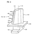
- FIG. 3 shows in perspective view a blade 120 or stator 130 of a turbomachine, which extends along a longitudinal axis 121 and which is repaired by the method according to the invention.
- the turbomachine may be a gas turbine of an aircraft or a power plant for power generation, a steam turbine or a compressor.
- the blade 120, 130 has along the longitudinal axis 121 consecutively a fastening region 400, a blade platform 403 adjoining thereto and an airfoil 406.
- the blade 130 may have at its blade tip 415 another platform (not shown).
- a blade root 183 is formed, which serves for attachment of the blades 120, 130 to a shaft or a disc (not shown).
- the blade root 183 is designed, for example, as a hammer head. Other designs as Christmas tree or Schwalbenschwanzfuß are possible.
- the blade 120, 130 has a leading edge 409 and a trailing edge 412 for a medium flowing past the airfoil 406.
- Such superalloys are for example from EP 1 204 776 B1 .
- EP 1 306 454 .
- the blade 120, 130 is hereby made by a casting process by means of directional solidification.
- Workpieces with a monocrystalline structure or structures are used as components for machines which are exposed to high mechanical, thermal and / or chemical stresses during operation.
- Such monocrystalline workpieces takes place e.g. by directed solidification from the melt.
- These are casting processes in which the liquid metallic alloy is transformed into a monocrystalline structure, i. to the single-crystal workpiece, or directionally solidified.
- dendritic crystals are aligned along the heat flux and form either a columnar grain structure (columnar, i.e., grains that run the full length of the workpiece and here, in common usage, are referred to as directionally solidified) or a monocrystalline structure, i. the whole workpiece consists of a single crystal.
- a columnar grain structure columnar, i.e., grains that run the full length of the workpiece and here, in common usage, are referred to as directionally solidified
- a monocrystalline structure i. the whole workpiece consists of a single crystal.
- directionally solidified structures we are referring to single crystals that are not grain boundaries or at most small-angle grain boundaries, as well as columnar crystal structures, which have well in the longitudinal direction extending grain boundaries, but no transverse grain boundaries. These second-mentioned crystalline structures are also known as directionally solidified structures.
- the blades 120, 130 may have coatings against corrosion or oxidation, e.g. M is at least one element of the group iron (Fe), cobalt (Co), nickel (Ni), X is an active element and stands for yttrium (Y) and / or silicon and / or at least one element of the rare ones Earth, or hafnium (Hf)).
- M is at least one element of the group iron (Fe), cobalt (Co), nickel (Ni)
- X is an active element and stands for yttrium (Y) and / or silicon and / or at least one element of the rare ones Earth, or hafnium (Hf)).
- Such alloys are known from the EP 0 486 489 B1 . EP 0 786 017 B1 . EP 0 412 397 B1 or EP 1 306 454 A1 which are to be part of this disclosure with regard to the chemical composition of the alloy.
- MCrAlX may still be present a thermal barrier coating and consists for example of ZrO 2 , Y 2 O 4 -ZrO 3 , that is, it is not, partially or completely stabilized by yttria and / or calcium oxide and / or magnesium oxide.
- Electron beam evaporation produces stalk-shaped grains in the thermal barrier coating.
- Refurbishment means that components 120, 130 may need to be deprotected after use (e.g., by sandblasting). This is followed by removal of the corrosion and / or oxidation layers or products. Optionally, even cracks in the component 120, 130 are repaired. This is followed by a re-coating of the component 120, 130 and a renewed use of the component 120, 130.
- the blade 120, 130 may be hollow or solid.
- the blade 120, 130 is to be cooled, it is hollow and may still film cooling holes 418 (indicated by dashed lines) on.
- the combustor 110 is configured as a so-called annular combustor wherein a plurality of burners 107 circumferentially disposed about an axis of rotation 102 open into a common combustor space 154 that creates flames 156.
- the combustion chamber 110 is configured in its entirety as an annular structure, which is positioned around the axis of rotation 102 around.
- the combustion chamber 110 is designed for a comparatively high temperature of the working medium M of about 1000 ° C to 1600 ° C.
- the combustion chamber wall 153 is provided on its side facing the working medium M side with an inner lining formed from heat shield elements 155.
- Each heat shield element 155 made of an alloy is equipped on the working medium side with a particularly heat-resistant protective layer (MCrAlX layer and / or ceramic coating) or is made of high-temperature-resistant material (solid ceramic blocks).
- M is at least one element of the group iron (Fe), cobalt (Co), nickel (Ni), X is an active element and stands for yttrium (Y) and / or silicon and / or at least one element of the rare earths, or hafnium (Hf).
- MCrAlX means: M is at least one element of the group iron (Fe), cobalt (Co), nickel (Ni), X is an active element and stands for yttrium (Y) and / or silicon and / or at least one element of the rare earths, or hafnium (Hf).
- Such alloys are known from the EP 0 486 489 B1 .
- EP 0 412 397 B1 or EP 1 306 454 A1 which are to be part of this disclosure with regard to the chemical composition of the alloy.
- MCrAlX may still be present, for example, a ceramic thermal barrier coating and consists for example of ZrO 2 , Y 2 O 4 -ZrO 2 , ie it is not, partially or completely stabilized by yttria and / or calcium oxide and / or magnesium oxide.
- Electron beam evaporation produces stalk-shaped grains in the thermal barrier coating.
- Refurbishment means that heat shield elements 155 may need to be deprotected (e.g., by sandblasting) after use. This is followed by removal of the corrosion and / or oxidation layers or products. If necessary, cracks in the heat shield element 155 are also repaired. This is followed by a recoating of the heat shield elements 155 and a renewed use of the heat shield elements 155.
- the heat shield elements 155 are then, for example, hollow and possibly still have film cooling holes (not shown) which open into the combustion chamber space 154.
- FIG. 5 shows by way of example a gas turbine 100 in a longitudinal partial section.
- the gas turbine 100 has inside a rotatably mounted about a rotation axis 102 rotor 103 with a shaft 101, which is also referred to as a turbine runner.
- an intake housing 104 a compressor 105, for example, a toroidal combustion chamber 110, in particular annular combustion chamber, with a plurality of coaxially arranged burners 107, a turbine 108 and the exhaust housing 109th
- a compressor 105 for example, a toroidal combustion chamber 110, in particular annular combustion chamber, with a plurality of coaxially arranged burners 107, a turbine 108 and the exhaust housing 109th
- the annular combustion chamber 110 communicates with an annular annular hot gas channel 111, for example. There, for example, form four successive turbine stages 112, the turbine 108th
- Each turbine stage 112 is formed, for example, from two blade rings. As seen in the direction of flow of a working medium 113, in the hot gas duct 111 of a row of guide vanes 115, a row 125 formed of rotor blades 120 follows.
- the guide vanes 130 are fastened to an inner housing 138 of a stator 143, whereas the moving blades 120 of a row 125 are attached to the rotor 103 by means of a turbine disk 133, for example.
- air 105 is sucked in and compressed by the compressor 105 through the intake housing 104.
- the compressed air provided at the turbine-side end of the compressor 105 is supplied to the burners 107 where it is mixed with a fuel.
- the mixture is then burned to form the working fluid 113 in the combustion chamber 110.
- the working medium 113 flows along the hot gas channel 111 past the guide vanes 130 and the rotor blades 120.
- the working medium 113 expands in a pulse-transmitting manner so that the rotor blades 120 drive the rotor 103 and drive the machine coupled to it.
- the components exposed to the hot working medium 113 are subject to thermal loads during operation of the gas turbine 100.
- the guide vanes 130 and rotor blades 120 of the first turbine stage 112, viewed in the flow direction of the working medium 113, are the most thermally stressed by the heat shield elements lining the annular combustion chamber 110.
- substrates of the components may have a directional structure, i. they are monocrystalline (SX structure) or have only longitudinal grains (DS structure).
- iron-, nickel- or cobalt-based superalloys are used as the material for the components, in particular for the turbine blade 120, 130 and components of the combustion chamber 110.
- Such superalloys are for example from EP 1 204 776 B1 .
- EP 1 306 454 .
- the blades 120, 130 may be anti-corrosion coatings (MCrAlX; M is at least one element of the group iron (Fe), cobalt (Co), nickel (Ni), X is an active element and is yttrium (Y) and / or silicon and / or at least one element of the rare earths or hafnium).
- M is at least one element of the group iron (Fe), cobalt (Co), nickel (Ni)
- X is an active element and is yttrium (Y) and / or silicon and / or at least one element of the rare earths or hafnium).
- Such alloys are known from the EP 0 486 489 B1 .
- EP 0 412 397 B1 or EP 1 306 454 A1 which should be part of this disclosure in terms of chemical composition.
- a thermal barrier coating On the MCrAlX may still be present a thermal barrier coating, and consists for example of ZrO 2 , Y 2 O 3 -ZrO 2 , that is, it is not, partially or completely stabilized by yttria and / or calcium oxide and / or magnesium oxide.
- suitable coating processes such as electron beam evaporation (EB-PVD), stalk-shaped grains are produced in the thermal barrier coating.
- the vane 130 has a guide vane foot (not shown here) facing the inner casing 138 of the turbine 108 and a vane head opposite the vane root.
- the vane head faces the rotor 103 and fixed to a mounting ring 140 of the stator 143.
Abstract
Description
Die vorliegende Erfindung betrifft ein Verfahren zum Reparieren eines Bauteils, welches ein Basismaterial mit einer gerichteten Mikrostruktur umfasst gemäß dem Oberbegriff des Anspruchs 1 (siche, z.B.,
Bauteile von Turbinen sind heutzutage nicht selten aus Materialien mit einer gerichteten Mikrostruktur hergestellt. Als Materialien mit einer gerichteten Mikrostruktur sollen hierbei insbesondere einkristalline Materialien und Materialien, die eine Kornstruktur aufweisen, wobei die Ausdehnung der Körner eine gemeinsame Vorzugsrichtung aufweist, anzusehen sein. Z.B. können die Körner in einer bestimmten Vorzugsrichtung eine größere Abmessung aufweisen, als in den übrigen Richtungen. Bauteile mit einer derartigen Kornstruktur werden auch als direktional erstarrte Bauteile (directional solidified) bezeichnet.Components of turbines are nowadays often made of materials with a directional microstructure. As materials with a directed microstructure, in particular monocrystalline materials and materials which have a grain structure, the extent of the grains having a common preferred direction, should be considered here. For example, For example, the grains may have a larger dimension in a certain preferred direction than in the other directions. Components with such a grain structure are also referred to as directionally solidified components.
Stark belastete Bauteile, wie etwa Turbinenschaufeln, unterliegen während des Betriebs einer hohen thermischen und mechanischen Beanspruchung, die zu Materialermüdungen und infolgedessen zu Rissen führen kann. Da das Herstellen von Bauteilen aus Basismaterialien, welche eine gerichtete Mikrostruktur aufweisen, relativ kostspielig ist, ist man in der Regel bemüht, derartige Bauteile nach Eintritt von Schädigungen zu reparieren. Damit wird die Funktionstüchtigkeit wieder hergestellt und das Bauteil für eine weitere Revisionsperiode einsetzbar.Heavily loaded components, such as turbine blades, are subject to high thermal and mechanical stress during operation, which can result in material fatigue and, as a result, cracking. Since the manufacture of components from base materials having a directional microstructure is relatively costly, it is usually endeavored to repair such components after damage has occurred. Thus, the functionality is restored and the component can be used for a further revision period.
Eine Möglichkeit der Reparatur beschädigter Bauteile ist beispielsweise das Löten. Bei diesem Löten wird ein Lot im Bereich der Beschädigung auf das Material des Bauteils, also auf das Basismaterial, aufgebracht und mittels Wärmeeinwirkung mit dem Basismaterial verbunden. Nach dem Löten weist das Lotmaterial jedoch bei der bisher üblichen Verfahrensweise keine einkristalline oder direktional erstarrte Struktur auf. Eine ungeordnete Struktur besitzt jedoch im Vergleich zu einer gerichteten Mikrostruktur schlechtere Materialeigenschaften - vor allem im Hochtemperaturbereich -, sodass die Lötstelle schlechtere Materialeigenschaften als das umgebende Basismaterial aufweist.One way of repairing damaged components is, for example, soldering. During this soldering, a solder in the region of the damage is applied to the material of the component, that is to say to the base material, and connected to the base material by means of heat. After soldering points However, the solder material in the usual procedure no monocrystalline or directionally solidified structure. However, a disordered structure has inferior material properties compared to a directional microstructure - especially in the high temperature region - such that the solder joint has poorer material properties than the surrounding base material.
Zum Reparieren von beschädigten Bauteilen mit einer gerichteten Mikrostruktur stehen Schweißverfahren zur Verfügung, mit denen auch gerichtete Mikrostrukturen in den verschweißten Strukturen erzeugt werden können. Ein derartiges Verfahren ist beispielsweise in
Weitere Verfahren bzw. zu verwendende Lotpulver sind bekannt aus den Publikationen
Die
Die
Die
Die
Die
Die
Schweißverfahren schmelzen jedoch immer das Basismaterial des zu reparierenden Bauteils auf. Strukturell tragende Bereiche eines Bauteils dürfen daher nicht geschweißt werden, da aufgrund des Aufschmelzens des Basismaterials die Integrität der gerichteten Struktur verloren ginge. Deshalb werden Bauteile mit einer gerichteten Mikrostruktur nur dann mittels der Schweißverfahren repariert, wenn sich die Beschädigungen nicht in strukturell tragenden Bereichen des Bauteils befinden. Befindet sich dagegen eine Beschädigung in einem strukturell tragenden Bereich des Bauteils so wird, falls eine gerichtete Schweißstruktur verlangt wird, dieses Bauteil als nicht reparierbar deklariert und gegen ein intaktes Bauteil ausgetauscht.However, welding processes always melt the base material of the component to be repaired. Structurally bearing areas of a component must therefore not be welded because the integrity of the directional structure would be lost due to the melting of the base material. Therefore, components with a directional microstructure are repaired by means of the welding process only if the damage is not in structurally bearing areas of the component. If, on the other hand, there is damage in a structurally bearing region of the component, if a directed welding structure is required, this component is declared as irreparable and replaced by an intact component.
Aufgabe der Erfindung ist es daher, ein Verfahren zur Verfügung zu stellen, mit dem beschädigte Bauteile, welche ein Basismaterial mit einer gerichteten Mikrostruktur umfassen, auch dann repariert werden können, wenn sich die Beschädigung in einem strukturell tragenden Bereich des Bauteils befindet.The object of the invention is therefore to provide a method by which damaged components comprising a base material with a directional microstructure can be repaired even if the damage is located in a structurally bearing region of the component.
Die Aufgabe wird durch ein Verfahren nach Anspruch 1 gelöst. Die abhängigen Ansprüche enthalten vorteilhafte Ausgestaltungen der vorliegenden Erfindung, die in vorteilhafter Art und Weise beliebig miteinander kombiniert werden können.The object is achieved by a method according to
In einem erfindungsgemäßen Verfahren zum Reparieren eines Bauteils, das ein Basismaterial mit einer gerichteten Mikrostruktur umfasst, erfolgt die Reparatur derart; dass die reparierte Stelle eine entsprechend gerichtete Mikrostruktur wie das umgebende Basismaterial aufweist. Das Basismaterial kann dabei insbesondere ein Material auf Nickelbasis sein. Im erfindungsgemäßen Verfahren wird ein Lot im Bereich einer zu reparierenden Stelle aufgebracht und mittels Wärmeeinwirkung mit dem Bauteil verlötet. Während der Wärmeeinwirkung wird dabei ein Temperaturgradient, d.h. ein Temperaturverlauf von einer höheren zu einer niedrigeren Temperatur, im Bereich der zu reparierenden Stelle erzeugt.In a method according to the invention for repairing a component comprising a base material with a directed microstructure, the repair is carried out in such a way; the repaired site has a suitably directed microstructure like the surrounding base material. The base material may in particular be a nickel-based material. In the method according to the invention, a solder is applied in the region of a point to be repaired and soldered to the component by means of heat. During the exposure to heat, a temperature gradient, i. a temperature profile from a higher to a lower temperature, generated in the area to be repaired.
Beim Lötprozess wird nur das Lot, nicht aber das Basismaterial, aufgeschmolzen und wieder erstarrten gelassen, wobei das Lot eine Verbindung mit dem Basismaterial eingeht, so dass das erfindungemäße Reparaturverfahren auch in strukturell tragenden Bereichen des Bauteils zur Anwendung kommen kann, ohne die guten Materialeigenschaften des Basismaterials zu beeinträchtigen. Mittels des Temperaturgradienten lässt sich ein epitaktisches Anwachsen und Erstarren des Lotes erzielen, also ein Wachstum, in welchem die kristalline Orientierung des Lots beim Erstarren von der des Substrates, also des Basismaterials, bestimmt wird. Der Temperaturgradient ermöglicht daher das Entstehen eines einkristallinen Lotbereiches oder einer anderen gerichteten Mikrostruktur im verlöteten Lot mit gegenüber einer ungerichteten Mikrostruktur ähnlich verbesserten Werkstoffeigenschaften. Das gerichtete Wachstum erfolgt dabei in Richtung des Temperaturgradienten, also in Richtung von der niedrigeren zu der höheren Temperatur. Aufgrund des gerichteten Wachstums und der daraus resultierenden gerichteten Mikrostruktur weist das verlötete Lot ähnlich gute Materialeigenschaften wie das Basismaterial des Bauteils auf.During the soldering process, only the solder, but not the base material, is melted and allowed to solidify again, the solder forming a bond with the base material, so that the repair method according to the invention can also be used in structurally bearing regions of the component without the good material properties of the component Base material. By means of the temperature gradient, it is possible to achieve an epitaxial growth and solidification of the solder, ie a growth in which the crystalline orientation of the solder during solidification is determined by the solidification of the substrate, ie the base material. The temperature gradient allows Therefore, the emergence of a single crystal Lotbereiches or other directional microstructure in the solder soldered with respect to an undirected microstructure similarly improved material properties. The directed growth takes place in the direction of the temperature gradient, ie in the direction from the lower to the higher temperature. Due to the directed growth and the resulting directional microstructure, the soldered solder has similarly good material properties as the base material of the component.
Vorzugsweise wird der Temperaturgradient im erfindungsgemäßen Reparaturverfahren derart erzeugt, dass er in Richtung der Orientierung der gerichteten Mikrostruktur des Basismaterials des Bauteils verläuft. Auf diese Weise lässt sich ein gerichtetes Wachstum des sich verfestigenden Lots in Richtung der Orientierung der gerichteten Mikrostruktur des Basismaterials erreichen.The temperature gradient in the repair method according to the invention is preferably produced such that it runs in the direction of the orientation of the directed microstructure of the base material of the component. In this way, directed growth of the solidifying solder in the direction of orientation of the directional microstructure of the base material can be achieved.
In einer vorteilhaften Weiterbildung des erfindungsgemäßen Verfahrens weist das Lot einen ersten Bestandteil mit einer Schmelztemperatur, die niedriger ist, vorzugsweise deutlich niedriger, als die Schmelztemperatur des Basismaterials des Bauteils und einen zweiten Bestandteil mit einer hohen Festigkeit und einer Schmelztemperatur, die über der Schmelztemperatur des ersten Bestandteils aber unterhalb der Schmelztemperatur bis hin zur Schmelztemperatur des Basismaterials liegt, auf. Das Lot wird in dieser Weiterbildung des Verfahrens derart im Bereich der zu lötenden Stelle aufgebracht, dass der Anteil am ersten Bestandteil im Lot in der örtlichen Nähe des Basismaterials höher ist als in einem vom Basismaterial weiter entfernten Bereich. In dieser Ausgestaltung des Verfahrens dient der erste Bestandteil mit der niedrigen Schmelztemperatur dazu, die Verbindung des Lots mit dem Basismaterial herzustellen, während der Bestandteil mit der hohen Schmelztemperatur für die Widerstandsfähigkeit (Festigkeit)des verlöteten Lots sorgt. Dadurch, dass das Lot im Bereich des Basismaterials einen höheren Anteil des ersten Bestandteils umfasst, lässt sich eine gute Verbindung des verlöteten Lots mit dem Basismaterial herstellen. Andererseits ist in Bereichen, die eine größere Entfernung vom Basismaterial aufweisen, verhältnismäßig mehr an zweitem Bestandteil, also am Bestandteil mit der höheren Widerstandsfähigkeit, vorhanden, sodass die beim späteren Betrieb des Bauteils einer stärkeren Belastung ausgesetzten Bereiche der Lötstelle eine hohe Widerstandsfähigkeit aufweisen.In an advantageous development of the method according to the invention, the solder has a first component with a melting temperature that is lower, preferably significantly lower, than the melting temperature of the base material of the component and a second component with a high strength and a melting temperature above the melting temperature of the first Constituent but below the melting temperature up to the melting temperature of the base material is on. In this development of the method, the solder is applied in the region of the spot to be soldered in such a way that the proportion of the first component in the solder in the local vicinity of the base material is higher than in a region further away from the base material. In this embodiment of the method, the first low melting temperature component serves to compound the solder to the base material, while the high melting temperature component provides the strength (strength) of the solder being soldered. Because the solder in the area of the base material has a higher proportion of the first constituent includes, a good connection of the soldered solder can be made with the base material. On the other hand, in areas having a greater distance from the base material, relatively more of the second component, ie the higher resistance component, is present, so that the areas of the solder joint exposed during later operation of the component have a high resistance.
Zum Bereitstellen der Wärmeeinwirkung wird im erfindungsgemäßen Verfahren laser-oder Elektvonstvahl verwendet.To provide the effect of heat laser or Elektvonstvahl is used in the process according to the invention.
In einer Weiterbildung des erfindungsgemäßen Verfahrens kann eine Wärmebehandlung des Basismaterials in den Prozess des Verlötens des Lotes integriert sein. Dadurch lässt sich gleichzeitig mit dem Reparieren ein Wiederaufbereiten (Rejuvenation) der Basismaterialeigenschaften realisieren. Weitere Merkmale, Eigenschaften und Vorteile der vorliegenden Erfindung ergeben sich aus der nachfolgenden Beschreibung eines Ausführungsbeispiels unter Bezugnahme auf die beiliegenden Zeichnungen.
- Figur 1a - 1c
- zeigen ein Ausführungsbeispiel für das erfindungsgemäße Verfahren,
- Figur 2
- zeigt eine Abwandlung des Ausführungsbeispieles,
Figur 3- zeigt eine Turbinenschaufel,
- Figur 4
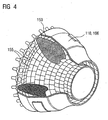
- zeigt eine Brennkammer,
- Figur 5
- zeigt eine Gasturbine.
- Figure 1a - 1c
- show an exemplary embodiment of the method according to the invention,
- FIG. 2
- shows a modification of the embodiment,
- FIG. 3
- shows a turbine blade,
- FIG. 4
- shows a combustion chamber,
- FIG. 5
- shows a gas turbine.
In
Das Basismaterial des Bauteils 1 umfasst eine Legierung vorzugsweise auf Nickelbasis und weist eine gerichtete Mikrostruktur, die in den Figuren durch kurze diagonal verlaufende Striche angedeutet ist, auf. Die Beschädigung 3 des Bauteils 1 befindet sich im Bereich der Oberfläche 5 und ist in der Figur als Vertiefung dargestellt.The base material of the
Zum Reparieren des geschädigten Bauteils 1 wird ein Lot 7, das im vorliegenden Ausführungsbeispiel vorzugsweise in Pulverform vorliegt, auf die die vorgereinigte beschädigte Stelle 3 aufgebracht und anschließend mittels Wärmeeinwirkung mit dem Basismaterial des Bauteils 1 verlötet (
Vorzugsweise wird das Lot 7 vor dem Aufschmelzen in die beschädigte Stelle 3 hineingedrückt. Das hat den Vorteil, dass die gesamte beschädigte Stelle 3 mit dem Lot 7 ausgefüllt wird. Insbesondere bei Rissen 3, die sehr tief ausgebildet sind (hohes Aspekt-Verhältnis) und eine ungleichförmige Querschnittsfläche haben, würde nach dem Stand der Technik eine äußere Pulverzufuhr mit einem Pulverförderer nicht gewährleisten, dass das Lot 7 bis zur Rissspitze gelangen kann.Preferably, the solder 7 is pressed into the damaged
Das Lot 7 kann in Form einer Paste, eines Schlickers, in reiner Pulverform oder mittels einer Folie aufgebracht und in die beschädigte Stelle 3 eingebracht werden. Weitere Formen der Einbringung oder Aufbringung sind denkbar.The solder 7 can be applied in the form of a paste, a slurry, in pure powder form or by means of a film and introduced into the damaged
Dabei ist es vorteilhaft, wenn die Materialzusammensetzung des Lotes 7 der des Bauteils 1 ähnlich ist.It is advantageous if the material composition of the solder 7 is similar to that of the
"Ähnlich" bedeutet, dass das Material des Lots 7 alle Elemente des Basismaterials aufweist zuzüglich zusätzlich einem oder mehreren Schmelzpunkterniedriger (z.B. Bor, Silizium). Das Lot 7 muss jedoch zumindest einen Bestandteil umfassen, dessen Schmelztemperatur niedriger ist, als die Schmelztemperatur des Basismaterials des Bauteils 1, damit mittels der Wärmeeinwirkung ein Aufschmelzen des Lotes 7, nicht jedoch des Basismaterials des Bauteils 1 erfolgt."Similar" means that the material of Lot 7 includes all elements of the base material plus one or more melting point depressants (e.g., boron, silicon). However, the solder 7 must comprise at least one constituent whose melting temperature is lower than the melting temperature of the base material of the
Vorzugsweise besteht das Lot 7 aus einem Bestandteil, d.h. das Lot 7 besteht aus einer Legierung und nicht aus einem Pulvergemisch von zwei Legierungen.Preferably, the solder 7 is composed of one component, i. The solder 7 is made of an alloy and not a mixed powder of two alloys.
Die Löttemperatur des Lots 7 beim Löten liegt , gemäß der Erfindung, um mindestens 30°C oder mindestens 50°C niedriger als die Schmelztemperatur des Basismaterials des Bauteils 1, sodass das Basismaterial nicht gefährdet ist. Vorzugsweise liegt der Unterschied zwischen der Löttemperatur und der Schmelztemperatur zwischen 50°C und 70°C. Dies ist insbesondere dann wichtig, wenn es sich bei dem Basismaterial um Superlegierungen handelt. Bei Superlegierungen verdampft bei hohen Temperaturen nahe seiner Schmelztemperaturen Chrom, sodass die Schmelztemperatur des Lots 7 möglichst gering gehalten und damit der Unterschied zwischen Löttemperaturen des Lots 7 und der Schmelztemperatur des Basismaterials möglichst groß gehalten werden soll.The soldering temperature of solder 7 during soldering is, according to the invention, at least 30 ° C or at least 50 ° C lower than the melting temperature of the base material of the
Der Unterschied in der Löttemperatur von Lot 7 und der Schmelztemperatur des Basismaterial beträgt vorzugsweise auch mindestens 70°C, vorzugsweise 70°C ± 4°C. Der maximale Unterschied in der Löttemperatur des Lots 7 und der Schmelztemperatur des Basismaterials liegt vorzugsweise bei 120°C.The difference in the soldering temperature of solder 7 and the melting temperature of the base material is preferably also at least 70 ° C, preferably 70 ° C ± 4 ° C. The maximum difference in the soldering temperature of the solder 7 and the Melting temperature of the base material is preferably 120 ° C.
Das Lot 7 wird vorzugsweise erst so aufgeschmolzen, dass es in die zu reparierende Stelle 3 hineinläuft.The solder 7 is preferably first melted so that it runs into the point to be repaired 3.
Die dazu notwendige Temperatur kann höher oder niedriger sein als die Temperaturen zur Einstellung der gerichteten Mikrostruktur.The temperature required for this may be higher or lower than the temperatures for adjusting the directional microstructure.
Bezüglich der zu verlötenden Superlegierung besteht keinerlei Einschränkung. Besonders vorteilhaft für die Anwendung des erfindungsgemäßen Lots 7 haben sich jedoch die Werkstoffe PWA 1483, PWA 1484 und RENE N5 herausgestellt. PWA 1483 hat einen Schmelzpunkt um 1341°C, RENE N5 weist einen Schmelzpunkt in der Region um 1360°C - 1370°C auf.There is no restriction on the superalloy to be soldered. However, the materials PWA 1483, PWA 1484 and RENE N5 have proven particularly advantageous for the application of the solder 7 according to the invention. PWA 1483 has a melting point of 1341 ° C, RENE N5 has a melting point in the region of 1360 ° C - 1370 ° C.
Die Schmelzpunkte der Lote 7 liegen zwischen beispielsweise bei 1160°C - 1220°C.The melting points of the solders 7 are between, for example, 1160 ° C - 1220 ° C.
Bei der Verwendung von hohen Temperaturen besteht außerdem das Problem der Rekristallation bei DS oder SX-Werkstoffen, sodass auch hier die Anforderung besteht, dass das Lot 7 in der Löttemperatur einen großen Unterschied zu der Schmelztemperatur des Basismaterials des Bauteils 1 aufweist.When using high temperatures, there is also the problem of recrystallization in DS or SX materials, so that there is also the requirement that the solder 7 in the soldering temperature has a large difference to the melting temperature of the base material of the
Um die Wärmeeinwirkung auf das Lot 7 zu verwirklichen, ist im vorliegenden Ausführungsbeispiel der erfindung vorzugsweise eine Elektronenstrahlkanone 9 vorhanden, welche das auf zuschmelzende Lot 7 bestrahlt und ihm so die zum Schmelzen nötige Wärme zuführt.In order to realize the effect of heat on the solder 7, in the present embodiment of the invention preferably an electron beam gun 9 is present, which irradiates the solder to be melted 7 and thus supplies him with the necessary heat for melting.
Die Elektronenstrahlbehandlung erfolgt vorzugsweise im Vakuum. Insbesondere bei oxidationsempfindlichen Materialien, wie z. B. bei Superlegierungen spielt die Oxidation eine wichtige Rolle, sodass eine Wärmebehandlung mittels eines Lasers oder eines Elektronenstrahls sowieso im Vakuum durchgeführt werden sollte. Die Elektronenstrahlbehandlung hat den Vorteil, dass sie zu einer besseren Energieeinkopplung in das Material führt und dass sich die Elektronenstrahlen berührungslos durch Spulen, die in dem Fall die Optik darstellen, über die zur reparierenden Stelle 3 bewegen lassen.The electron beam treatment is preferably carried out in vacuo. In particular, in oxidation-sensitive materials such. For example, in superalloys, oxidation plays an important role, so that a heat treatment by means of a laser or an electron beam should be carried out anyway in a vacuum. The electron beam treatment has the advantage that it leads to a better energy coupling into the material and that the electron beams contact by coils, which in this case the optics represent over the move to the repairing
Die Wärmeeinwirkung auf das Lot 7 kann auch, gemäß der Erfindung, mittels Laserstrahl erfolgen.The effect of heat on the solder 7 can also be done according to the invention by means of laser beam.
Die Laserleistung oder die Leistung der Elektronenstrahlen ist so gemessen, dass sie das Lot 7 vollständig aufschmelzen und auf Löttemperatur bringen kann. Dabei liegt die Löttemperatur des Lots 7 teilweise um bis zu 140° über der Schmelztemperatur des Lots 7.The laser power or the power of the electron beams is measured so that it can completely melt the solder 7 and bring it to soldering temperature. The soldering temperature of the solder 7 is partially up to 140 ° above the melting temperature of the solder 7.
Die Leistung eines Nd-YAG Lasers liegt dabei vorzugsweise zwischen 1500 und 2000W.The power of an Nd-YAG laser is preferably between 1500 and 2000W.
Erfindungsgemäß wird während des Lötvorgangs gezielt in Vorzugsrichtung der Mikrostruktur des Basismaterials ein Temperaturgradient im Bereich der Beschädigung 3 hergestellt. Das Herstellen des Temperaturgradienten kann, gemäß der Erfindung dadurch erfolgen, indem das Bauteil 1 und die Elektronenstrahlkanone 9 relativ zueinander bewegt werden. Im Ausführungsbeispiel wird daher die Elektronenstrahlkanone 9 parallel zur Oberfläche 5 über das Lot 7 geführt. Die Geschwindigkeit, mit der das Führen der Elektronenstrahlkanone 9 über das Lot 7 erfolgt, ist gemäß der Erfindung, dabei derart gewählt, dass sich der gewünschte Temperaturgradient im Bereich der Beschädigung 3, d.h. im Lot 7, einstellt. Der Temperaturgradient induziert dabei das Entstehen einer epitaktisch gerichteten Mikrostruktur, wenn das durch die Elektronenstrahlkanone 9 aufgeschmolzene Lot 7 wieder erstarrt. Die Steilheit des Temperaturgradienten kann dabei beispielsweise durch die Geschwindigkeit, mit der Elektronenstrahlkanone 9 und Bauteil 1 relativ zueinander bewegt werden, oder die Leistung eingestellt werden. Unter der Steilheit des Gradienten ist hierbei die Zu- oder Abnahme der Temperatur pro Längeneinheit zu verstehen. Die Steilheit des Temperaturgradienten, die zum Entstehen einer gerichteten Mikrostruktur im sich verfestigenden Lot 7 führt, hängt dabei von der Zusammensetzung des Lotes 7 ab.According to the invention, a temperature gradient in the region of the
Der Temperaturgradient, der eingestellt werden muss, ergibt sich aus dem so genannten GV-Diagramm, das für verschiedene Metalle und metallische Legierungen unterschiedlich ist und für jede Legierung berechnet oder experimentell bestimmt werden muss. Eine Kurve L in dem GV-Diagramm trennt den Bereich der beiden Parameter Erstarrungsgeschwindigkeit und Temperaturgradient, in welchem die Legierung globulistisch erstarrt von jenem, in welchem die Legierung zu einem dendritisch gerichteten Gefüge erstarrt. Eine Beschreibung und Erklärung des GV-Diagramms befindet sich z.B. im
Der Temperaturgradient bestimmt sich aus der Löttemperatur des Lots 7 und der Temperatur des Bauteils auf der Rückseite der zur reparierenden Stelle 3.The temperature gradient is determined by the soldering temperature of the solder 7 and the temperature of the component on the back of the
Vorzugsweise wird das Bauteil 1 nicht gekühlt oder auf Raumtemperatur gehalten oder gegebenenfalls bis auf 300° vorgewärmt, wie es in den Schriften
Verfahren zum Herstellen von einkristallinen Strukturen mittels eines Lasers oder in äquivalenter Weise von Elektronenstrahlen sind auch in der
Im vorliegenden Ausführungsbeispiel erstreckt sich die Vorzugsrichtung der gerichteten Mikrostruktur im Basismaterial des Bauteils 1 innerhalb der Zeichenebene von links nach rechts. Um im erstarrenden Lot 7 das Entstehen einer gerichteten Mikrostruktur zu induzieren, deren Vorzugsrichtung mit der im Basismaterial übereinstimmt, erfolgt die Bewegung der Elektronenstrahlkanone 9 relativ zum Bauteil 1 parallel zur Vorzugsrichtung der gerichteten Mikrostruktur des Basismaterials.In the present exemplary embodiment, the preferred direction of the directed microstructure in the base material of the
Wenn das Bauteil 1 eine SX-Struktur aufweist kann die reparierte Stelle 3 ebenfalls eine SX- aber auch eine DS-Struktur aufweisen.If the
Wenn das Bauteil 1 eine DS-Struktur aufweist kann die reparierte Stelle 3 ebenfalls eine DS- aber auch eine SX-Struktur aufweisen.If the
Vorzugweise weisen Bauteil 1 und reparierte Stelle 3 die gleiche Mikrostruktur auf.Preferably,
Ebenso braucht das Bauteil 1 keine gerichtet erstarrte Struktur aufzuweisen, wobei in der reparierten Stelle 3 durch die gerichtet erstarrte Struktur bei hohen Temperaturen eine hohe Festigkeit des Bauteils 1 erreicht wird, weil die gerichtet erstarrte Struktur des Lots 7 in der reparierten Stelle den negativen Effekt des niedrigen Schmelzpunkts auf die mechanische Festigkeit bei hohen Temperaturen ausgleicht.Likewise, the
Eine Breite b (
Vorzugsweise liegt die Breite b der zu reparierenden Stelle 3 zwischen 5µm und 300µm.The width b of the
Ebenso vorteilhaft ist es, dass die zu reparierende Stelle 3 eine Breite b zwischen 5µm und 100µm aufweist.It is equally advantageous that the point to be repaired 3 has a width b between 5 .mu.m and 100 .mu.m.
Weiterhin sind können Breiten b eines Risses zwischen 20µm und 300µm repariert werdenFurthermore, widths b of a crack between 20μm and 300μm can be repaired
Vorzugsweise weist die zu reparierende Stelle 3 Breiten b zwischen 20µm und 100µm auf.The point to be repaired 3 preferably has widths b between 20 μm and 100 μm.
Ebenso vorzugsweise weist die zu reparierende Stelle 3 eine Breite zwischen 50µm und 300µm auf.Also preferably, the point to be repaired 3 has a width between 50 .mu.m and 300 .mu.m.
Weitere Vorteile werden erzielt, wenn die zu reparierende Stelle 3 eine Breite b zwischen 50µm und 200µm aufweist. Außerdem werden Risse 3, die eine Breite zwischen 50µm und 100µm aufweisen, in vorteilhafter Art und Weise durch das Verfahren repariert.Further advantages are achieved if the point to be repaired 3 has a width b between 50 .mu.m and 200 .mu.m. In addition, cracks 3 having a width between 50μm and 100μm are advantageously repaired by the method.
Bezüglich der Länge der zu reparierenden Stelle gibt es keinerlei Beschränkungen. Hier muss jedoch der Laser 9 und die Elektronenstrahlen in Längsrichtung gegebenenfalls (in die Zeichnungsebene hinein) verfahren werden, wobei der Laser in dieser Richtung, wie in der
Die Haltezeiten des Laser- oder Elektronenstrahls richten sich nach dem Material und nach der Geschwindigkeit der Erstarrung.The holding times of the laser or electron beam depend on the material and the rate of solidification.
Ebenso kann der Elektronenstrahl so aufgeweitet sein, dass er beispielsweise das gesamte Lot 7 bestrahlt und jedenfalls dadurch ganz erwärmt.Likewise, the electron beam can be widened so that it irradiates, for example, the entire solder 7 and in any case completely heated by it.
Ein Verfahren der Elektronenstrahlkanone ist also nicht unbedingt notwendig.A method of the electron gun is therefore not absolutely necessary.
Durch die Abfuhr von Wärme des Lots 7 in das Substrat des Bauteils 1 entsteht innerhalb des Lots 7 ein Temperaturgradient. An der äußeren Oberfläche des Lots 7 ist, gemäß der Erfindung die Temperatur am höchsten und an der Grenzfläche des Lots 7 zu dem Substrat des Bauteils 1 hin ist es kälter. Ggf. kann, gemäß der Erfindung das Bauteil 1 auf der Rückseite, der Beschädigung 3 gegenüber oder irgendwo sonst gekühlt oder erwärmt werden, um einen gewünschten bestimmten Temperaturgradienten in Abhängigkeit von der Geometrie des Bauteils 1 und der Beschädigung 3 einzustellen.By dissipating heat of the solder 7 in the substrate of the
Im vorliegenden Ausführungsbeispiel wurde zum Zuführen der Wärme eine Elektronenstrahlkanone 9 verwendet.In the present embodiment, an electron beam gun 9 was used to supply the heat.
Eine Abwandlung des mit Bezug auf die
Das Auftragen des pulverförmigen Lots 17 auf die vorgereinigte beschädigte Stelle 3 erfolgt derart, dass zuerst eine Lotzusammensetzung 18 aufgetragen wird, in welcher der erste Bestandteil einen relativ hohen Anteil am Pulver ausmacht. Anschließend wird eine Lotzusammensetzung 19 aufgetragen, in der der erste Bestandteil gegenüber dem zweiten Bestandteil verringert ist. Wenn nun ein Verlöten des Lots 17 mit dem Basismaterial erfolgt, erleichtert der hohe Anteil des ersten Bestandteils, also des Bestandteils mit der niedrigen Schmelztemperatur, ein einfaches Verlöten des Lots mit dem Basismaterial, wo hingegen die Lotzusammensetzung 19, in dem der Anteil des ersten Bestandteils verringert ist, eine höhere Festigkeit der reparierten Stelle gewährleistet.The
Ebenso ist es möglich, dass die Lotzusammensetzung 18 eine höhere Festigkeit der zu reparierenden Stelle 3 gewährleistet und die oberflächennähere Lotzusammensetzung 19 einen höheren Oxidations- und/oder Korrosionsschutz aufweist.It is likewise possible for the
Statt diesem zweischichtigen Aufbau des Lots 7 kann das Lot 7 in der zu reparierenden Stelle 3 einen Materialgradienten vom Grund der Stelle 3 bis zur Oberfläche 5 des Bauteils aufweisen, in dem sich die Zusammensetzung des Lots 7 kontinuierlich verändert.Instead of this two-layer structure of the solder 7, the solder 7 in the point to be repaired 3 may have a material gradient from the bottom of the
In beiden Ausführungsvarianten des erfindungsgemäßen Verfahrens ist es auch möglich, die Wärmeeinwirkung zum Verlöten des Lotes 7, 17 mit dem Basismaterial des Bauteils 1 gleichzeitig zum Durchführen einer Wärmebehandlung des Basismaterials zu verwenden, um so eine Wiederaufbereitung (Rejuvenation) der Basismaterialeigenschaften zu ermöglichen.In both embodiments of the method according to the invention, it is also possible to use the heat for soldering the
Im beschriebenen Ausführungsbeispiel und seiner Abwandlung wird das Lot 7, 17 in Pulverform auf die zu reparierende Stelle aufgetragen. Alternativ kann es jedoch auch als Folie oder Paste aufgetragen werden.In the described embodiment and its modification, the
Das Pulver des Lots 7, 17 liegt beispielsweise als Nanopulver vor, d. h. die Korngrößen des Pulvers sind kleiner 500 oder kleiner 300 oder kleiner 100 Nanometer. Es hat sich nämlich herausgestellt, dass ein Lot 7 aus Nanopulver eine niedrigere Schmelztemperatur gegenüber einem konventionellen Pulver derselben Zusammensetzung mit mikrometergroßen Körnern aufweist. Ebenso kann das Pulver des Lots 7, 17 aus einem Gemisch von Nanopulver und konventionellen Pulver, d. h. einem Pulver, das Korngrößen im Mikrometerbereich aufweist, bestehen. Dadurch kann die Schmelzpunkterniedrigung gezielt eingestellt werden.The powder of the
Ebenso kann die Folie oder die Paste, mittels der das Lot 7 aufgetragen wird, teilweise oder ganz ein Pulver aus Nanopulver aufweisen.Likewise, the film or the paste, by means of which the solder 7 is applied, can comprise partially or completely a powder of nanopowders.
Der Vorteil gegenüber dem Stand der Technik besteht darin, dass hier das Pulver nicht über einen Pulverförderer zugeführt wird, sondern bereits verdichtet der zu reparierenden Stelle 3 zugeführt wird. Ein Nanopulver über eine Düse einer zu reparierenden Stelle 3 zuzuführen, wie es aus dem Stand der Technik bekannt ist, ist fast unmöglich, da die Körner des Nanopulvers viel zu klein sind und beim Sprühen sehr breit streuen würden.The advantage over the prior art is that here the powder is not supplied via a powder conveyor, but already compressed the point to be repaired 3 is supplied. It is almost impossible to deliver a nanopowder via a nozzle to a
Die Strömungsmaschine kann eine Gasturbine eines Flugzeugs oder eines Kraftwerks zur Elektrizitätserzeugung, eine Dampfturbine oder ein Kompressor sein.The turbomachine may be a gas turbine of an aircraft or a power plant for power generation, a steam turbine or a compressor.
Die Schaufel 120, 130 weist entlang der Längsachse 121 aufeinander folgend einen Befestigungsbereich 400, eine daran angrenzende Schaufelplattform 403 sowie ein Schaufelblatt 406 auf.The
Als Leitschaufel 130 kann die Schaufel 130 an ihrer Schaufelspitze 415 eine weitere Plattform aufweisen (nicht dargestellt).As a
Im Befestigungsbereich 400 ist ein Schaufelfuß 183 gebildet, der zur Befestigung der Laufschaufeln 120, 130 an einer Welle oder einer Scheibe dient (nicht dargestellt).In the mounting
Der Schaufelfuß 183 ist beispielsweise als Hammerkopf ausgestaltet. Andere Ausgestaltungen als Tannenbaum- oder Schwalbenschwanzfuß sind möglich.The
Die Schaufel 120, 130 weist für ein Medium, das an dem Schaufelblatt 406 vorbeiströmt, eine Anströmkante 409 und eine Abströmkante 412 auf.The
Bei herkömmlichen Schaufeln 120, 130 werden in allen Bereichen 400, 403, 406 der Schaufel 120, 130 beispielsweise massive metallische Werkstoffe, insbesondere Superlegierungen verwendet.In
Solche Superlegierungen sind beispielsweise aus der
Die Schaufel 120, 130 ist hierbei durch ein Gussverfahren mittels gerichteter Erstarrung gefertigt.The
Werkstücke mit einkristalliner Struktur oder Strukturen werden als Bauteile für Maschinen eingesetzt, die im Betrieb hohen mechanischen, thermischen und/oder chemischen Belastungen ausgesetzt sind.Workpieces with a monocrystalline structure or structures are used as components for machines which are exposed to high mechanical, thermal and / or chemical stresses during operation.
Die Fertigung von derartigen einkristallinen Werkstücken erfolgt z.B. durch gerichtetes Erstarren aus der Schmelze. Es handelt sich dabei um Gießverfahren, bei denen die flüssige metallische Legierung zur einkristallinen Struktur, d.h. zum einkristallinen Werkstück, oder gerichtet erstarrt.The production of such monocrystalline workpieces takes place e.g. by directed solidification from the melt. These are casting processes in which the liquid metallic alloy is transformed into a monocrystalline structure, i. to the single-crystal workpiece, or directionally solidified.
Dabei werden dendritische Kristalle entlang dem Wärmefluss ausgerichtet und bilden entweder eine stängelkristalline Kornstruktur (kolumnar, d.h. Körner, die über die ganze Länge des Werkstückes verlaufen und hier, dem allgemeinen Sprachgebrauch nach, als gerichtet erstarrt bezeichnet werden) oder eine einkristalline Struktur, d.h. das ganze Werkstück besteht aus einem einzigen Kristall. In diesen Verfahren muss man den Übergang zur globulitischen (polykristallinen) Erstarrung meiden, da sich durch ungerichtetes Wachstum notwendigerweise transversale und longitudinale Korngrenzen ausbilden, welche die guten Eigenschaften des gerichtet erstarrten oder einkristallinen Bauteiles zunichte machen.Here, dendritic crystals are aligned along the heat flux and form either a columnar grain structure (columnar, i.e., grains that run the full length of the workpiece and here, in common usage, are referred to as directionally solidified) or a monocrystalline structure, i. the whole workpiece consists of a single crystal. In these processes, it is necessary to avoid the transition to globulitic (polycrystalline) solidification, since non-directional growth necessarily forms transverse and longitudinal grain boundaries which negate the good properties of the directionally solidified or monocrystalline component.
Ist allgemein von gerichtet erstarrten Gefügen die Rede, so sind damit sowohl Einkristalle gemeint, die keine Korngrenzen oder höchstens Kleinwinkelkorngrenzen aufweisen, als auch Stängelkristallstrukturen, die wohl in longitudinaler Richtung verlaufende Korngrenzen, aber keine transversalen Korngrenzen aufweisen. Bei diesen zweitgenannten kristallinen Strukturen spricht man auch von gerichtet erstarrten Gefügen (directionally solidified structures).If we speak of directionally solidified structures in general, we are referring to single crystals that are not grain boundaries or at most small-angle grain boundaries, as well as columnar crystal structures, which have well in the longitudinal direction extending grain boundaries, but no transverse grain boundaries. These second-mentioned crystalline structures are also known as directionally solidified structures.
Solche Verfahren sind aus der
Ebenso können die Schaufeln 120, 130 Beschichtungen gegen Korrosion oder Oxidation aufweisen, z. B. (MCrA1X; M ist zumindest ein Element der Gruppe Eisen (Fe), Kobalt (Co), Nickel (Ni), X ist ein Aktivelement und steht für Yttrium (Y) und/oder Silizium und/oder zumindest ein Element der Seltenen Erden, bzw. Hafnium (Hf)). Solche Legierungen sind bekannt aus der
Auf der MCrAlX kann noch eine Wärmedämmschicht vorhanden sein und besteht beispielsweise aus ZrO2, Y2O4-ZrO3, d.h. sie ist nicht, teilweise oder vollständig stabilisiert durch Yttriumoxid und/oder Kalziumoxid und/oder Magnesiumoxid.On the MCrAlX may still be present a thermal barrier coating and consists for example of ZrO 2 , Y 2 O 4 -ZrO 3 , that is, it is not, partially or completely stabilized by yttria and / or calcium oxide and / or magnesium oxide.
Durch geeignete Beschichtungsverfahren wie z.B. Elektronenstrahlverdampfen (EB-PVD) werden stängelförmige Körner in der Wärmedämmschicht erzeugt.By suitable coating methods, e.g. Electron beam evaporation (EB-PVD) produces stalk-shaped grains in the thermal barrier coating.
Wiederaufarbeitung (Refurbishment) bedeutet, dass Bauteile 120, 130 nach ihrem Einsatz gegebenenfalls von Schutzschichten befreit werden müssen (z.B. durch Sandstrahlen). Danach erfolgt eine Entfernung der Korrosions- und/oder Oxidationsschichten bzw. -produkte. Gegebenenfalls werden auch noch Risse im Bauteil 120, 130 repariert. Danach erfolgt eine Wiederbeschichtung des Bauteils 120, 130 und ein erneuter Einsatz des Bauteils 120, 130.Refurbishment means that
Die Schaufel 120, 130 kann hohl oder massiv ausgeführt sein.The
Wenn die Schaufel 120, 130 gekühlt werden soll, ist sie hohl und weist ggf. noch Filmkühllöcher 418 (gestrichelt angedeutet) auf.If the
Die
Zur Erzielung eines vergleichsweise hohen Wirkungsgrades ist die Brennkammer 110 für eine vergleichsweise hohe Temperatur des Arbeitsmediums M von etwa 1000°C bis 1600°C ausgelegt. Um auch bei diesen, für die Materialien ungünstigen Betriebsparametern eine vergleichsweise lange Betriebsdauer zu ermöglichen, ist die Brennkammerwand 153 auf ihrer dem Arbeitsmedium M zugewandten Seite mit einer aus Hitzeschildelementen 155 gebildeten Innenauskleidung versehen.To achieve a comparatively high efficiency, the
Jedes Hitzeschildelement 155 aus einer Legierung ist arbeitsmediumsseitig mit einer besonders hitzebeständigen Schutzschicht (MCrAlX-Schicht und/oder keramische Beschichtung) ausgestattet oder ist aus hochtemperaturbeständigem Material (massive keramische Steine) gefertigt.Each
Diese Schutzschichten können ähnlich der Turbinenschaufeln sein, also bedeutet beispielsweise MCrAlX: M ist zumindest ein Element der Gruppe Eisen (Fe), Kobalt (Co), Nickel (Ni), X ist ein Aktivelement und steht für Yttrium (Y) und/oder Silizium und/oder zumindest ein Element der Seltenen Erden, bzw. Hafnium (Hf). Solche Legierungen sind bekannt aus der
Auf der MCrAlX kann noch eine beispielsweise keramische Wärmedämmschicht vorhanden sein und besteht beispielsweise aus ZrO2, Y2O4-ZrO2, d.h. sie ist nicht, teilweise oder vollständig stabilisiert durch Yttriumoxid und/oder Kalziumoxid und/oder Magnesiumoxid.On the MCrAlX may still be present, for example, a ceramic thermal barrier coating and consists for example of ZrO 2 , Y 2 O 4 -ZrO 2 , ie it is not, partially or completely stabilized by yttria and / or calcium oxide and / or magnesium oxide.
Durch geeignete Beschichtungsverfahren wie z.B. Elektronenstrahlverdampfen (EB-PVD) werden stängelförmige Körner in der Wärmedämmschicht erzeugt.By suitable coating methods, e.g. Electron beam evaporation (EB-PVD) produces stalk-shaped grains in the thermal barrier coating.
Wiederaufarbeitung (Refurbishment) bedeutet, dass Hitzeschildelemente 155 nach ihrem Einsatz gegebenenfalls von Schutzschichten befreit werden müssen (z.B. durch Sandstrahlen). Danach erfolgt eine Entfernung der Korrosions- und/oder Oxidationsschichten bzw. -produkte. Gegebenenfalls werden auch noch Risse in dem Hitzeschildelement 155 repariert. Danach erfolgt eine Wiederbeschichtung der Hitzeschildelemente 155 und ein erneuter Einsatz der Hitzeschildelemente 155.Refurbishment means that
Aufgrund der hohen Temperaturen im Inneren der Brennkammer 110 kann zudem für die Hitzeschildelemente 155 bzw. für deren Halteelemente ein Kühlsystem vorgesehen sein. Die Hitzeschildelemente 155 sind dann beispielsweise hohl und weisen ggf. noch in den Brennkammerraum 154 mündende Filmkühllöcher (nicht dargestellt) auf.Due to the high temperatures inside the
Die
Die Gasturbine 100 weist im Inneren einen um eine Rotationsachse 102 drehgelagerten Rotor 103 mit einer Welle 101 auf, der auch als Turbinenläufer bezeichnet wird.The
Entlang des Rotors 103 folgen aufeinander ein Ansauggehäuse 104, ein Verdichter 105, eine beispielsweise torusartige Brennkammer 110, insbesondere Ringbrennkammer, mit mehreren koaxial angeordneten Brennern 107, eine Turbine 108 und das Abgasgehäuse 109.Along the
Die Ringbrennkammer 110 kommuniziert mit einem beispielsweise ringförmigen Heißgaskanal 111. Dort bilden beispielsweise vier hintereinander geschaltete Turbinenstufen 112 die Turbine 108.The
Jede Turbinenstufe 112 ist beispielsweise aus zwei Schaufelringen gebildet. In Strömungsrichtung eines Arbeitsmediums 113 gesehen folgt im Heißgaskanal 111 einer Leitschaufelreihe 115 eine aus Laufschaufeln 120, gebildete Reihe 125.Each
Die Leitschaufeln 130 sind dabei an einem Innengehäuse 138 eines Stators 143 befestigt, wohingegen die Laufschaufeln 120 einer Reihe 125 beispielsweise mittels einer Turbinenscheibe 133 am Rotor 103 angebracht sind.The guide vanes 130 are fastened to an inner housing 138 of a stator 143, whereas the moving
An dem Rotor 103 angekoppelt ist ein Generator oder eine Arbeitsmaschine (nicht dargestellt).Coupled to the
Während des Betriebes der Gasturbine 100 wird vom Verdichter 105 durch das Ansauggehäuse 104 Luft 135 angesaugt und verdichtet. Die am turbinenseitigen Ende des Verdichters 105 bereitgestellte verdichtete Luft wird zu den Brennern 107 geführt und dort mit einem Brennmittel vermischt. Das Gemisch wird dann unter Bildung des Arbeitsmediums 113 in der Brennkammer 110 verbrannt. Von dort aus strömt das Arbeitsmedium 113 entlang des Heißgaskanals 111 vorbei an den Leitschaufeln 130 und den Laufschaufeln 120. An den Laufschaufeln 120 entspannt sich das Arbeitsmedium 113 impulsübertragend, so dass die Laufschaufeln 120 den Rotor 103 antreiben und dieser die an ihn angekoppelte Arbeitsmaschine.During operation of the
Die dem heißen Arbeitsmedium 113 ausgesetzten Bauteile unterliegen während des Betriebes der Gasturbine 100 thermischen Belastungen. Die Leitschaufeln 130 und Laufschaufeln 120 der in Strömungsrichtung des Arbeitsmediums 113 gesehen ersten Turbinenstufe 112 werden nebel den die Ringbrennkammer 110 auskleidenden Hitzeschildelementen am meisten thermisch belastet.The components exposed to the hot working
Um den dort herrschenden Temperaturen standzuhalten, können diese mittels eines Kühlmittels gekühlt werden.To withstand the prevailing temperatures, they can be cooled by means of a coolant.
Ebenso können Substrate der Bauteile eine gerichtete Struktur aufweisen, d.h. sie sind einkristallin (SX-Struktur) oder weisen nur längsgerichtete Körner auf (DS-Struktur).Likewise, substrates of the components may have a directional structure, i. they are monocrystalline (SX structure) or have only longitudinal grains (DS structure).
Als Material für die Bauteile, insbesondere für die Turbinenschaufel 120, 130 und Bauteile der Brennkammer 110 werden beispielsweise eisen-, nickel- oder kobaltbasierte Superlegierungen verwendet.As the material for the components, in particular for the
Solche Superlegierungen sind beispielsweise aus der
Ebenso können die Schaufeln 120, 130 Beschichtungen gegen Korrosion (MCrAlX; M ist zumindest ein Element der Gruppe Eisen (Fe), Kobalt (Co), Nickel (Ni), X ist ein Aktivelement und steht für Yttrium (Y) und/oder Silizium und/oder zumindest ein Element der Seltenen Erden bzw. Hafnium). Solche Legierungen sind bekannt aus der
Auf der MCrAlX kann noch eine Wärmedämmschicht vorhanden sein, und besteht beispielsweise aus ZrO2, Y2O3-ZrO2, d.h. sie ist nicht, teilweise oder vollständig stabilisiert durch Yttriumoxid und/oder Kalziumoxid und/oder Magnesiumoxid. Durch geeignete Beschichtungsverfahren wie z.B. Elektronenstrahlverdampfen (EB-PVD) werden stängelförmige Körner in der Wärmedämmschicht erzeugt.On the MCrAlX may still be present a thermal barrier coating, and consists for example of ZrO 2 , Y 2 O 3 -ZrO 2 , that is, it is not, partially or completely stabilized by yttria and / or calcium oxide and / or magnesium oxide. By means of suitable coating processes, such as electron beam evaporation (EB-PVD), stalk-shaped grains are produced in the thermal barrier coating.
Die Leitschaufel 130 weist einen dem Innengehäuse 138 der Turbine 108 zugewandten Leitschaufelfuß (hier nicht dargestellt) und einen dem Leitschaufelfuß gegenüberliegenden Leitschaufelkopf auf. Der Leitschaufelkopf ist dem Rotor 103 zugewandt und an einem Befestigungsring 140 des Stators 143 festgelegt.The
Claims (24)
- Repair process for repairing a component (1),
which comprises a base material with a directional microstructure,
in which process a solder (7, 17) is applied in the region of a location (3) that is to be repaired,
wherein the solder (7) is melted but the base material of the component (1) is not, characterized in that
the solder (7, 17) comprises a constituent,
the soldering temperature of which is at least 30°C lower than the melting temperature of the base material, and
then is soldered to the component (1) with the action of heat by means of electron beams or laser beams,
in that the temperature is highest at the outer surface of the solder (7) and cooler at the interface between the solder (7) and the substrate of the component (1), and
wherein a relative velocity of the electron beam or of the laser beam and component (1) with respect to one another or the electron beam power or the laser power or a heating or a cooling on the rear side with respect to the damage (3) is selected in such a way as to generate a temperature gradient in the region of the location (3) that is to be repaired,
so that the same directional microstructure is generated in the repaired location (3) as the surrounding base material. - Process according to Claim 1,
characterized in that
the difference between the soldering temperature of the solder (7, 17) and the melting temperature of the base material of the component (1) is at least 50°C. - Process according to Claim 1,
characterized in that
the difference between the soldering temperature of the solder (7, 17) and the melting temperature of the base material of the component (1) is at least 70°C. - Process according to Claim 1,
characterized in that
the difference between the soldering temperature of the solder (7, 17) and the melting temperature of the base material is 70°C ± 4°C. - Process according to Claim 1, 2, 3 or 4,
characterized in that
first of all the solder (7, 17) is completely applied and then it is completely melted. - Process according to Claim 1, 2, 3 or 4,
characterized in that
the component (1) consists of a nickel- or cobalt-base superalloy,
in particular of Rene N5, PWA 1483 or PWA 1484. - Process according to Claim 1, 5 or 6,
characterized in that
the temperature gradient is oriented in such a manner that it extends in the direction of the orientation of the directional microstructure of the base material of the component (1). - Process according to one or more of the preceding claims, characterized
in that the solder (17) comprises a first constituent with a melting temperature, which is lower than the melting temperature of the base material of the component (1) and a second constituent with a high durability and a melting temperature
which is above the melting temperature of the first constituent but below the melting temperature of the base material up to the melting temperature of the base material, and
in that the solder (17) is applied in such a manner in the region of the location that is to be soldered
that the proportion of first constituent in the solder (17) is higher in the vicinity (18) of the base material than in a region (19) further away from the base material. - Process according to one or more of Claims 1, 7 or 8,
in which the temperature gradient is produced by means of an optical heating operation or an inductive heating operation. - Process according to one or more of Claims 1, 7 to 8,
in which the temperature gradient is produced by means of a casting furnace for producing a casting with a directionally directed microstructure. - Process according to one or more of Claims 1 to 10,
in which a heat treatment of the base material is integrated into the process of soldering the solder (7, 17). - Process according to one or more of the preceding claims,
characterized in that
the powder of the solder (7, 17) partly, and in particular completely, comprises nano-powder. - Process according to Claim 1 or 5,
characterized in that
the solder (7, 17) is introduced onto or into the location (3) that is to be repaired in the form of a paste, a slurry or a foil. - Process according to Claim 1, 2, 3 or 4,
characterized in that
the solder (7) comprises just one constituent. - Process according to Claim 1,
characterized in that
the location (3) that is to be repaired has a width (b) of between 1 µm and 1000 µm. - Process according to Claim 1,
characterized in that
the laser power or the power of the electron beams is such that it partially melts the solder (7, 17). - Process according to Claim 1 or 16,
characterized in that
the speed of travel or holding times of the laser beams or electron beams is such
that the solder (7, 17) solidifies in dendritic form in the region of the location (3) that is to be repaired. - Process according to Claim 1, 5, 6, 8, 15 or 16,
characterized in that
the temperature gradient is determined by the soldering temperature of the solder (7, 17) and the temperature of the component (1),
and in particular the temperature of the component (1) is 300° or room temperature. - Process according to Claim 15,
characterized in that
the location (3) that is to be repaired has a width (b) of between 1 µm and 500 µm. - Process according to Claim 15,
characterized in that
the location (3) that is to be repaired has a width (b) of between 400 µm and 600 µm in particular around 500 µm. - The process according to Claim 15,
characterized in that
the location (3) that is to be repaired has a width (b) of between 500 µm and 1000 µm, in particular around 750 µm. - Process according to Claim 15,
characterized in that
the location (3) that is to be repaired has a width (b) of between 500 µm and 750 µm. - Process according to Claim 15,
characterized in that
the location (3) that is to be repaired has a width (b) of between 750 µm and 1000 µm. - Process according to Claim 1, 2, 3, 4, 5, 7,
characterized in that
the action of heat is effected by laser beams, in particular in vacuo.
Applications Claiming Priority (1)
| Application Number | Priority Date | Filing Date | Title |
|---|---|---|---|
| PCT/EP2005/008038 WO2007012338A1 (en) | 2005-07-22 | 2005-07-22 | Method of repairing a component comprising a directed microstructure, by setting a temperature gradient during exposure to the laser heat; a component produced by such a method |
Publications (2)
| Publication Number | Publication Date |
|---|---|
| EP1910006A1 EP1910006A1 (en) | 2008-04-16 |
| EP1910006B1 true EP1910006B1 (en) | 2011-12-21 |
Family
ID=36001020
Family Applications (1)
| Application Number | Title | Priority Date | Filing Date |
|---|---|---|---|
| EP05774084A Not-in-force EP1910006B1 (en) | 2005-07-22 | 2005-07-22 | Method of repairing a component comprising a directed microstructure, by setting a temperature gradient during exposure to a electron or a laser heat |
Country Status (6)
| Country | Link |
|---|---|
| US (1) | US8141769B2 (en) |
| EP (1) | EP1910006B1 (en) |
| JP (1) | JP2009502503A (en) |
| CN (1) | CN101272880B (en) |
| AT (1) | ATE537928T1 (en) |
| WO (1) | WO2007012338A1 (en) |
Families Citing this family (22)
| Publication number | Priority date | Publication date | Assignee | Title |
|---|---|---|---|---|
| DE102006026704A1 (en) * | 2006-06-08 | 2007-12-13 | Mtu Aero Engines Gmbh | Process for the manufacture or repair of turbine or engine components, and component, namely turbine or engine component |
| FR2906172A1 (en) * | 2006-09-22 | 2008-03-28 | Snecma Services Sa | Blade`s defect e.g. crack, repairing method for e.g. low pressure distributor part, of aircraft`s turbomachine, involves heating damaging zone by generating induced current using inductor for passing powder to liquid state |
| EP1930116A3 (en) | 2006-12-07 | 2010-06-23 | Turbine Overhaul Services Private Limited | Method of diffusion brazing with nonoparticle alloys |
| EP1967312A1 (en) * | 2007-03-06 | 2008-09-10 | Siemens Aktiengesellschaft | Method for repair soldering of a component under vacuum and a selected oxygen partial pressure |
| FR2921856B1 (en) * | 2007-10-05 | 2011-12-09 | Snecma | PROCESS FOR RETOUCHING METAL PIECES |
| EP2078579A1 (en) * | 2008-01-10 | 2009-07-15 | Siemens Aktiengesellschaft | Method for soldering one component and component with soldering and welding points |
| SG155778A1 (en) * | 2008-03-10 | 2009-10-29 | Turbine Overhaul Services Pte | Method for diffusion bonding metallic components with nanoparticle foil |
| EP2226149A1 (en) * | 2009-03-04 | 2010-09-08 | Siemens Aktiengesellschaft | Two-step welding method |
| US20120231295A1 (en) * | 2011-03-08 | 2012-09-13 | General Electric Company | Method of fabricating a component and a component |
| CH705662A1 (en) * | 2011-11-04 | 2013-05-15 | Alstom Technology Ltd | Process for producing articles of a solidified by gamma-prime nickel-base superalloy excretion by selective laser melting (SLM). |
| US8942462B2 (en) * | 2012-04-12 | 2015-01-27 | GM Global Technology Operations LLC | Method for automatic quantification of dendrite arm spacing in dendritic microstructures |
| US10415390B2 (en) | 2012-05-11 | 2019-09-17 | Siemens Energy, Inc. | Repair of directionally solidified alloys |
| EP2754527A1 (en) * | 2013-01-11 | 2014-07-16 | Siemens Aktiengesellschaft | Creation of fine grains during build-up welding |
| US9056443B2 (en) * | 2013-02-04 | 2015-06-16 | General Electric Company | Brazing process, braze arrangement, and brazed article |
| US9254537B2 (en) * | 2013-12-19 | 2016-02-09 | Siemens Energy, Inc. | Plural layer putty-powder/slurry application method for superalloy component crack vacuum furnace healing |
| EP3216554B1 (en) * | 2016-03-09 | 2020-05-06 | MTU Aero Engines GmbH | Component with wear- resistant openings and depressions and method for producing the same |
| EP3441180A1 (en) * | 2017-08-11 | 2019-02-13 | General Electric Company | Method of repairing superalloys |
| US10976052B2 (en) | 2017-10-25 | 2021-04-13 | General Electric Company | Volute trapped vortex combustor assembly |
| US10976053B2 (en) | 2017-10-25 | 2021-04-13 | General Electric Company | Involute trapped vortex combustor assembly |
| US11181269B2 (en) | 2018-11-15 | 2021-11-23 | General Electric Company | Involute trapped vortex combustor assembly |
| JP7270428B2 (en) | 2019-03-19 | 2023-05-10 | 三菱重工業株式会社 | Directionally solidified material, turbine rotor blade and method for repairing unidirectionally solidified material |
| CN111151834A (en) * | 2019-12-26 | 2020-05-15 | 浙江大学 | Brazing repair method for local leakage of vacuum brazing aluminum plate-fin heat exchanger core |
Family Cites Families (52)
| Publication number | Priority date | Publication date | Assignee | Title |
|---|---|---|---|---|
| US4222794A (en) * | 1979-07-02 | 1980-09-16 | United Technologies Corporation | Single crystal nickel superalloy |
| US4448618A (en) * | 1983-02-28 | 1984-05-15 | Allied Corporation | Nickel based brazing filler metals |
| JPS6195769A (en) * | 1984-10-17 | 1986-05-14 | Toshiba Corp | Fixing method corrosion preventing member to steam turbine blade |
| US4900394A (en) | 1985-08-22 | 1990-02-13 | Inco Alloys International, Inc. | Process for producing single crystals |
| US4705203A (en) * | 1986-08-04 | 1987-11-10 | United Technologies Corporation | Repair of surface defects in superalloy articles |
| US4830934A (en) | 1987-06-01 | 1989-05-16 | General Electric Company | Alloy powder mixture for treating alloys |
| US4878953A (en) | 1988-01-13 | 1989-11-07 | Metallurgical Industries, Inc. | Method of refurbishing cast gas turbine engine components and refurbished component |
| US5165463A (en) * | 1988-11-10 | 1992-11-24 | Lanxide Technology Company, Lp | Directional solidification of metal matrix composites |
| US4987736A (en) | 1988-12-14 | 1991-01-29 | General Electric Company | Lightweight gas turbine engine frame with free-floating heat shield |
| WO1991002108A1 (en) | 1989-08-10 | 1991-02-21 | Siemens Aktiengesellschaft | High-temperature-resistant, corrosion-resistant coating, in particular for components of gas turbines |
| DE3926479A1 (en) | 1989-08-10 | 1991-02-14 | Siemens Ag | RHENIUM-PROTECTIVE COATING, WITH GREAT CORROSION AND / OR OXIDATION RESISTANCE |
| US5206213A (en) * | 1990-03-23 | 1993-04-27 | International Business Machines Corp. | Method of preparing oriented, polycrystalline superconducting ceramic oxides |
| US5240491A (en) * | 1991-07-08 | 1993-08-31 | General Electric Company | Alloy powder mixture for brazing of superalloy articles |
| JP3073616B2 (en) | 1992-12-24 | 2000-08-07 | キヤノン株式会社 | Information processing device with multiple probes |
| EP0631832B1 (en) | 1993-07-02 | 1998-05-20 | ALD Vacuum Technologies GmbH | Method and apparatus for directional solidification of a metal melt |
| US5783318A (en) | 1994-06-22 | 1998-07-21 | United Technologies Corporation | Repaired nickel based superalloy |
| UA39902C2 (en) | 1994-08-08 | 2001-07-16 | Сіменс Акцієнгезельшафт | METHOD AND DEVICE FOR DIRECTED HARDENING OF MELT |
| DE59505454D1 (en) | 1994-10-14 | 1999-04-29 | Siemens Ag | PROTECTIVE LAYER FOR PROTECTING A COMPONENT AGAINST CORROSION, OXIDATION AND THERMAL OVERLOAD AND METHOD FOR THEIR PRODUCTION |
| US5523170A (en) | 1994-12-28 | 1996-06-04 | General Electric Company | Repaired article and material and method for making |
| US5561827A (en) * | 1994-12-28 | 1996-10-01 | General Electric Company | Coated nickel-base superalloy article and powder and method useful in its preparation |
| US5666643A (en) | 1995-02-23 | 1997-09-09 | General Electric Company | High temperature braze material |
| US5664616A (en) * | 1996-02-29 | 1997-09-09 | Caterpillar Inc. | Process for pressure infiltration casting and fusion bonding of a metal matrix composite component in a metallic article |
| WO1998005450A1 (en) | 1996-08-06 | 1998-02-12 | Siemens Aktiengesellschaft | Process and device for directed solidification of a melt |
| US5806751A (en) | 1996-10-17 | 1998-09-15 | United Technologies Corporation | Method of repairing metallic alloy articles, such as gas turbine engine components |
| DE19647313A1 (en) | 1996-11-13 | 1998-05-14 | Siemens Ag | Method and device for the directional solidification of a melt |
| US5873703A (en) | 1997-01-22 | 1999-02-23 | General Electric Company | Repair of gamma titanium aluminide articles |
| EP0892090B1 (en) | 1997-02-24 | 2008-04-23 | Sulzer Innotec Ag | Method for manufacturing single crystal structures |
| EP0861927A1 (en) | 1997-02-24 | 1998-09-02 | Sulzer Innotec Ag | Method for manufacturing single crystal structures |
| DE19714530A1 (en) * | 1997-04-08 | 1998-10-15 | Asea Brown Boveri | Process for soldering directionally solidified or single-crystal components |
| CN2296989Y (en) | 1997-06-06 | 1998-11-11 | 上虞市华通汽车配件厂 | Turbulator |
| WO1999067435A1 (en) | 1998-06-23 | 1999-12-29 | Siemens Aktiengesellschaft | Directionally solidified casting with improved transverse stress rupture strength |
| US6331361B1 (en) * | 1998-11-19 | 2001-12-18 | Hickham Industries, Inc. | Methods for manufacture and repair and resulting components with directionally solidified or single crystal materials |
| US6231692B1 (en) | 1999-01-28 | 2001-05-15 | Howmet Research Corporation | Nickel base superalloy with improved machinability and method of making thereof |
| US6283356B1 (en) | 1999-05-28 | 2001-09-04 | General Electric Company | Repair of a recess in an article surface |
| JP2003529677A (en) | 1999-07-29 | 2003-10-07 | シーメンス アクチエンゲゼルシヤフト | Heat resistant structural member and method of manufacturing the same |
| JP2001089258A (en) * | 1999-09-21 | 2001-04-03 | Kurimoto Ltd | Joining member and alumina ceramics-stainless steel joined body using the member |
| US6491207B1 (en) | 1999-12-10 | 2002-12-10 | General Electric Company | Weld repair of directionally solidified articles |
| GC0000233A (en) | 2000-08-07 | 2006-03-29 | Exxonmobil Upstream Res Co | Weld metals with superior low temperature toughness for joining high strength, low alloy steels |
| US6454885B1 (en) | 2000-12-15 | 2002-09-24 | Rolls-Royce Corporation | Nickel diffusion braze alloy and method for repair of superalloys |
| US6495793B2 (en) | 2001-04-12 | 2002-12-17 | General Electric Company | Laser repair method for nickel base superalloys with high gamma prime content |
| ATE283936T1 (en) | 2001-05-14 | 2004-12-15 | Alstom Technology Ltd | METHOD FOR ISOTHERMAL BRAZING OF SINGLE CRYSTALLINE OBJECTS |
| US6503349B2 (en) | 2001-05-15 | 2003-01-07 | United Technologies Corporation | Repair of single crystal nickel based superalloy article |
| DE50104022D1 (en) | 2001-10-24 | 2004-11-11 | Siemens Ag | Protective layer containing rhenium to protect a component against corrosion and oxidation at high temperatures |
| EP1319729B1 (en) | 2001-12-13 | 2007-04-11 | Siemens Aktiengesellschaft | High temperature resistant part, made of single-crystal or polycrystalline nickel-base superalloy |
| US7416108B2 (en) * | 2002-01-24 | 2008-08-26 | Siemens Power Generation, Inc. | High strength diffusion brazing utilizing nano-powders |
| EP1340567A1 (en) | 2002-02-27 | 2003-09-03 | ALSTOM (Switzerland) Ltd | Method of removing casting defects |
| EP1495166B1 (en) | 2002-04-15 | 2007-05-09 | Siemens Aktiengesellschaft | Method for producing for producing mono-crystalline structures |
| EP1424158B1 (en) * | 2002-11-29 | 2007-06-27 | Alstom Technology Ltd | A method for fabricating, modifying or repairing of single crystal or directionally solidified articles |
| EP1437426A1 (en) | 2003-01-10 | 2004-07-14 | Siemens Aktiengesellschaft | Process for producing single crystal structures |
| JP2005000940A (en) * | 2003-06-10 | 2005-01-06 | Toshiba Corp | Brazing filler of multi-layer lamination type, and method for brazing-repair |
| US7051435B1 (en) * | 2003-06-13 | 2006-05-30 | General Electric Company | Process for repairing turbine components |
| EP1561536A1 (en) * | 2004-02-03 | 2005-08-10 | Siemens Aktiengesellschaft | Process of brazing repairing of a part having a base material with oriented microstructure |
-
2005
- 2005-07-22 US US11/989,214 patent/US8141769B2/en not_active Expired - Fee Related
- 2005-07-22 JP JP2008521807A patent/JP2009502503A/en active Pending
- 2005-07-22 WO PCT/EP2005/008038 patent/WO2007012338A1/en active Application Filing
- 2005-07-22 AT AT05774084T patent/ATE537928T1/en active
- 2005-07-22 CN CN200580051135XA patent/CN101272880B/en not_active Expired - Fee Related
- 2005-07-22 EP EP05774084A patent/EP1910006B1/en not_active Not-in-force
Also Published As
| Publication number | Publication date |
|---|---|
| CN101272880A (en) | 2008-09-24 |
| US20100000976A1 (en) | 2010-01-07 |
| EP1910006A1 (en) | 2008-04-16 |
| WO2007012338A1 (en) | 2007-02-01 |
| ATE537928T1 (en) | 2012-01-15 |
| US8141769B2 (en) | 2012-03-27 |
| CN101272880B (en) | 2012-03-21 |
| JP2009502503A (en) | 2009-01-29 |
Similar Documents
| Publication | Publication Date | Title |
|---|---|---|
| EP1910006B1 (en) | Method of repairing a component comprising a directed microstructure, by setting a temperature gradient during exposure to a electron or a laser heat | |
| EP1954844B1 (en) | Method for repairing cracks in components and solder material for soldering components | |
| EP1957685B1 (en) | Method for repairing cracks in components | |
| EP1759806B1 (en) | Brazing process for repairing a crack | |
| EP2311597B1 (en) | Method of laser welding workpieces from heat resistant superalloys with control of some laser welding parameters for reaching a particular cooling rate | |
| EP2317078B2 (en) | Abrasive single-crystal turbine blade | |
| EP1772228A1 (en) | Process for repairing a workpiece with an oriented microstructure | |
| EP2322313A1 (en) | Method for welding workpieces from extremely heat-proof superalloys with particular feeding rate of the welding filler material | |
| WO2006074857A2 (en) | Method for producing a hole and corresponding device | |
| EP1976660A1 (en) | Method for the production of a hole | |
| EP2078579A1 (en) | Method for soldering one component and component with soldering and welding points | |
| WO2009143909A1 (en) | Method and device for welding workpieces made of high-temperature resistant super alloys | |
| EP1867423A1 (en) | Process for repairing a workpiece through soldering with a sheet coated with solder | |
| EP1645653A1 (en) | Coating system | |
| WO2008095531A1 (en) | Brazing composition and brazing method for superalloys | |
| WO2009124802A1 (en) | Welding method with a controlled temperature profile and device therefor | |
| EP1967313A1 (en) | Component and a solder | |
| EP1816316A1 (en) | Method for Repairing a Component | |
| WO2006040221A1 (en) | Method for producing a layer system | |
| WO2008087084A1 (en) | Powder mixture with blocky powders method for use of the powder mixture and components | |
| WO2009100794A1 (en) | Method for fusing curved surfaces, and a device | |
| EP2226149A1 (en) | Two-step welding method | |
| EP1797985A1 (en) | Method and device for welding | |
| WO2006069822A1 (en) | Method for the production of a hole | |
| EP1930115A1 (en) | Wire, use of a wire and welding process |
Legal Events
| Date | Code | Title | Description |
|---|---|---|---|
| PUAI | Public reference made under article 153(3) epc to a published international application that has entered the european phase |
Free format text: ORIGINAL CODE: 0009012 |
|
| 17P | Request for examination filed |
Effective date: 20080114 |
|
| AK | Designated contracting states |
Kind code of ref document: A1 Designated state(s): AT BE BG CH CY CZ DE DK EE ES FI FR GB GR HU IE IS IT LI LT LU LV MC NL PL PT RO SE SI SK TR |
|
| RIN1 | Information on inventor provided before grant (corrected) |
Inventor name: VOLEK, ANDREAS Inventor name: SINGER, ROBERT Inventor name: OTT, MICHAEL Inventor name: PAUL, UWE |
|
| RIN1 | Information on inventor provided before grant (corrected) |
Inventor name: PAUL, UWE Inventor name: VOLEK, ANDREAS Inventor name: SINGER, ROBERT Inventor name: OTT, MICHAEL |
|
| RIN1 | Information on inventor provided before grant (corrected) |
Inventor name: PAUL, UWE Inventor name: SINGER, ROBERT Inventor name: VOLEK, ANDREAS Inventor name: OTT, MICHAEL |
|
| 17Q | First examination report despatched |
Effective date: 20080908 |
|
| GRAP | Despatch of communication of intention to grant a patent |
Free format text: ORIGINAL CODE: EPIDOSNIGR1 |
|
| RTI1 | Title (correction) |
Free format text: METHOD OF REPAIRING A COMPONENT COMPRISING A DIRECTED MICROSTRUCTURE, BY SETTING A TEMPERATURE GRADIENT DURING EXPOSURE TO A ELECTRON OR A LASER HEAT |
|
| GRAS | Grant fee paid |
Free format text: ORIGINAL CODE: EPIDOSNIGR3 |
|
| DAX | Request for extension of the european patent (deleted) | ||
| GRAA | (expected) grant |
Free format text: ORIGINAL CODE: 0009210 |
|
| AK | Designated contracting states |
Kind code of ref document: B1 Designated state(s): AT BE BG CH CY CZ DE DK EE ES FI FR GB GR HU IE IS IT LI LT LU LV MC NL PL PT RO SE SI SK TR |
|
| REG | Reference to a national code |
Ref country code: GB Ref legal event code: FG4D Free format text: NOT ENGLISH |
|
| REG | Reference to a national code |
Ref country code: CH Ref legal event code: NV Representative=s name: SIEMENS SCHWEIZ AG Ref country code: CH Ref legal event code: PUEA Owner name: SIEMENS AKTIENGESELLSCHAFT Free format text: MTU AERO ENGINES GMBH#DACHAUER STRASSE 665#80995 MUENCHEN (DE) $ SIEMENS AKTIENGESELLSCHAFT#WITTELSBACHERPLATZ 2#80333 MUENCHEN (DE) -TRANSFER TO- SIEMENS AKTIENGESELLSCHAFT#WITTELSBACHERPLATZ 2#80333 MUENCHEN (DE) Ref country code: CH Ref legal event code: EP |
|
| REG | Reference to a national code |
Ref country code: AT Ref legal event code: REF Ref document number: 537928 Country of ref document: AT Kind code of ref document: T Effective date: 20120115 |
|
| REG | Reference to a national code |
Ref country code: IE Ref legal event code: FG4D |
|
| REG | Reference to a national code |
Ref country code: DE Ref legal event code: R096 Ref document number: 502005012256 Country of ref document: DE Effective date: 20120223 |
|
| REG | Reference to a national code |
Ref country code: GB Ref legal event code: 732E Free format text: REGISTERED BETWEEN 20120301 AND 20120307 |
|
| REG | Reference to a national code |
Ref country code: NL Ref legal event code: VDEP Effective date: 20111221 |
|
| PG25 | Lapsed in a contracting state [announced via postgrant information from national office to epo] |
Ref country code: LT Free format text: LAPSE BECAUSE OF FAILURE TO SUBMIT A TRANSLATION OF THE DESCRIPTION OR TO PAY THE FEE WITHIN THE PRESCRIBED TIME-LIMIT Effective date: 20111221 |
|
| LTIE | Lt: invalidation of european patent or patent extension |
Effective date: 20111221 |
|
| PG25 | Lapsed in a contracting state [announced via postgrant information from national office to epo] |
Ref country code: SI Free format text: LAPSE BECAUSE OF FAILURE TO SUBMIT A TRANSLATION OF THE DESCRIPTION OR TO PAY THE FEE WITHIN THE PRESCRIBED TIME-LIMIT Effective date: 20111221 Ref country code: NL Free format text: LAPSE BECAUSE OF FAILURE TO SUBMIT A TRANSLATION OF THE DESCRIPTION OR TO PAY THE FEE WITHIN THE PRESCRIBED TIME-LIMIT Effective date: 20111221 Ref country code: LV Free format text: LAPSE BECAUSE OF FAILURE TO SUBMIT A TRANSLATION OF THE DESCRIPTION OR TO PAY THE FEE WITHIN THE PRESCRIBED TIME-LIMIT Effective date: 20111221 Ref country code: GR Free format text: LAPSE BECAUSE OF FAILURE TO SUBMIT A TRANSLATION OF THE DESCRIPTION OR TO PAY THE FEE WITHIN THE PRESCRIBED TIME-LIMIT Effective date: 20120322 Ref country code: SE Free format text: LAPSE BECAUSE OF FAILURE TO SUBMIT A TRANSLATION OF THE DESCRIPTION OR TO PAY THE FEE WITHIN THE PRESCRIBED TIME-LIMIT Effective date: 20111221 |
|
| REG | Reference to a national code |
Ref country code: DE Ref legal event code: R081 Ref document number: 502005012256 Country of ref document: DE Owner name: SIEMENS AKTIENGESELLSCHAFT, DE Free format text: FORMER OWNER: MTU AERO ENGINES GMBH, SIEMENS AKTIENGESELLSCHAFT, , DE Effective date: 20120424 Ref country code: DE Ref legal event code: R081 Ref document number: 502005012256 Country of ref document: DE Owner name: SIEMENS AKTIENGESELLSCHAFT, DE Free format text: FORMER OWNERS: MTU AERO ENGINES GMBH, 80995 MUENCHEN, DE; SIEMENS AKTIENGESELLSCHAFT, 80333 MUENCHEN, DE Effective date: 20120424 |
|
| PG25 | Lapsed in a contracting state [announced via postgrant information from national office to epo] |
Ref country code: CY Free format text: LAPSE BECAUSE OF FAILURE TO SUBMIT A TRANSLATION OF THE DESCRIPTION OR TO PAY THE FEE WITHIN THE PRESCRIBED TIME-LIMIT Effective date: 20111221 |
|
| REG | Reference to a national code |
Ref country code: IE Ref legal event code: FD4D |
|
| PG25 | Lapsed in a contracting state [announced via postgrant information from national office to epo] |
Ref country code: IS Free format text: LAPSE BECAUSE OF FAILURE TO SUBMIT A TRANSLATION OF THE DESCRIPTION OR TO PAY THE FEE WITHIN THE PRESCRIBED TIME-LIMIT Effective date: 20120421 Ref country code: IE Free format text: LAPSE BECAUSE OF FAILURE TO SUBMIT A TRANSLATION OF THE DESCRIPTION OR TO PAY THE FEE WITHIN THE PRESCRIBED TIME-LIMIT Effective date: 20111221 Ref country code: BG Free format text: LAPSE BECAUSE OF FAILURE TO SUBMIT A TRANSLATION OF THE DESCRIPTION OR TO PAY THE FEE WITHIN THE PRESCRIBED TIME-LIMIT Effective date: 20120321 Ref country code: CZ Free format text: LAPSE BECAUSE OF FAILURE TO SUBMIT A TRANSLATION OF THE DESCRIPTION OR TO PAY THE FEE WITHIN THE PRESCRIBED TIME-LIMIT Effective date: 20111221 Ref country code: EE Free format text: LAPSE BECAUSE OF FAILURE TO SUBMIT A TRANSLATION OF THE DESCRIPTION OR TO PAY THE FEE WITHIN THE PRESCRIBED TIME-LIMIT Effective date: 20111221 Ref country code: SK Free format text: LAPSE BECAUSE OF FAILURE TO SUBMIT A TRANSLATION OF THE DESCRIPTION OR TO PAY THE FEE WITHIN THE PRESCRIBED TIME-LIMIT Effective date: 20111221 |
|
| PG25 | Lapsed in a contracting state [announced via postgrant information from national office to epo] |
Ref country code: RO Free format text: LAPSE BECAUSE OF FAILURE TO SUBMIT A TRANSLATION OF THE DESCRIPTION OR TO PAY THE FEE WITHIN THE PRESCRIBED TIME-LIMIT Effective date: 20111221 Ref country code: PT Free format text: LAPSE BECAUSE OF FAILURE TO SUBMIT A TRANSLATION OF THE DESCRIPTION OR TO PAY THE FEE WITHIN THE PRESCRIBED TIME-LIMIT Effective date: 20120423 Ref country code: PL Free format text: LAPSE BECAUSE OF FAILURE TO SUBMIT A TRANSLATION OF THE DESCRIPTION OR TO PAY THE FEE WITHIN THE PRESCRIBED TIME-LIMIT Effective date: 20111221 |
|
| PLBE | No opposition filed within time limit |
Free format text: ORIGINAL CODE: 0009261 |
|
| STAA | Information on the status of an ep patent application or granted ep patent |
Free format text: STATUS: NO OPPOSITION FILED WITHIN TIME LIMIT |
|
| PG25 | Lapsed in a contracting state [announced via postgrant information from national office to epo] |
Ref country code: DK Free format text: LAPSE BECAUSE OF FAILURE TO SUBMIT A TRANSLATION OF THE DESCRIPTION OR TO PAY THE FEE WITHIN THE PRESCRIBED TIME-LIMIT Effective date: 20111221 |
|
| 26N | No opposition filed |
Effective date: 20120924 |
|
| REG | Reference to a national code |
Ref country code: DE Ref legal event code: R097 Ref document number: 502005012256 Country of ref document: DE Effective date: 20120924 |
|
| BERE | Be: lapsed |
Owner name: SIEMENS A.G. Effective date: 20120731 Owner name: MTU AERO ENGINES G.M.B.H. Effective date: 20120731 |
|
| PG25 | Lapsed in a contracting state [announced via postgrant information from national office to epo] |
Ref country code: MC Free format text: LAPSE BECAUSE OF NON-PAYMENT OF DUE FEES Effective date: 20120731 |
|
| PG25 | Lapsed in a contracting state [announced via postgrant information from national office to epo] |
Ref country code: ES Free format text: LAPSE BECAUSE OF FAILURE TO SUBMIT A TRANSLATION OF THE DESCRIPTION OR TO PAY THE FEE WITHIN THE PRESCRIBED TIME-LIMIT Effective date: 20120401 |
|
| PG25 | Lapsed in a contracting state [announced via postgrant information from national office to epo] |
Ref country code: BE Free format text: LAPSE BECAUSE OF NON-PAYMENT OF DUE FEES Effective date: 20120731 |
|
| PG25 | Lapsed in a contracting state [announced via postgrant information from national office to epo] |
Ref country code: FI Free format text: LAPSE BECAUSE OF FAILURE TO SUBMIT A TRANSLATION OF THE DESCRIPTION OR TO PAY THE FEE WITHIN THE PRESCRIBED TIME-LIMIT Effective date: 20111221 |
|
| REG | Reference to a national code |
Ref country code: AT Ref legal event code: MM01 Ref document number: 537928 Country of ref document: AT Kind code of ref document: T Effective date: 20120731 |
|
| PG25 | Lapsed in a contracting state [announced via postgrant information from national office to epo] |
Ref country code: AT Free format text: LAPSE BECAUSE OF NON-PAYMENT OF DUE FEES Effective date: 20120731 |
|
| PG25 | Lapsed in a contracting state [announced via postgrant information from national office to epo] |
Ref country code: TR Free format text: LAPSE BECAUSE OF FAILURE TO SUBMIT A TRANSLATION OF THE DESCRIPTION OR TO PAY THE FEE WITHIN THE PRESCRIBED TIME-LIMIT Effective date: 20111221 |
|
| PG25 | Lapsed in a contracting state [announced via postgrant information from national office to epo] |
Ref country code: LU Free format text: LAPSE BECAUSE OF NON-PAYMENT OF DUE FEES Effective date: 20120722 |
|
| PG25 | Lapsed in a contracting state [announced via postgrant information from national office to epo] |
Ref country code: HU Free format text: LAPSE BECAUSE OF FAILURE TO SUBMIT A TRANSLATION OF THE DESCRIPTION OR TO PAY THE FEE WITHIN THE PRESCRIBED TIME-LIMIT Effective date: 20050722 |
|
| PGFP | Annual fee paid to national office [announced via postgrant information from national office to epo] |
Ref country code: DE Payment date: 20140919 Year of fee payment: 10 |
|
| PGFP | Annual fee paid to national office [announced via postgrant information from national office to epo] |
Ref country code: GB Payment date: 20140709 Year of fee payment: 10 Ref country code: FR Payment date: 20140709 Year of fee payment: 10 |
|
| PGFP | Annual fee paid to national office [announced via postgrant information from national office to epo] |
Ref country code: IT Payment date: 20140729 Year of fee payment: 10 |
|
| PGFP | Annual fee paid to national office [announced via postgrant information from national office to epo] |
Ref country code: CH Payment date: 20141009 Year of fee payment: 10 |
|
| REG | Reference to a national code |
Ref country code: DE Ref legal event code: R119 Ref document number: 502005012256 Country of ref document: DE |
|
| REG | Reference to a national code |
Ref country code: CH Ref legal event code: PL |
|
| GBPC | Gb: european patent ceased through non-payment of renewal fee |
Effective date: 20150722 |
|
| PG25 | Lapsed in a contracting state [announced via postgrant information from national office to epo] |
Ref country code: IT Free format text: LAPSE BECAUSE OF NON-PAYMENT OF DUE FEES Effective date: 20150722 Ref country code: CH Free format text: LAPSE BECAUSE OF NON-PAYMENT OF DUE FEES Effective date: 20150731 Ref country code: DE Free format text: LAPSE BECAUSE OF NON-PAYMENT OF DUE FEES Effective date: 20160202 Ref country code: GB Free format text: LAPSE BECAUSE OF NON-PAYMENT OF DUE FEES Effective date: 20150722 Ref country code: LI Free format text: LAPSE BECAUSE OF NON-PAYMENT OF DUE FEES Effective date: 20150731 |
|
| REG | Reference to a national code |
Ref country code: FR Ref legal event code: ST Effective date: 20160331 |
|
| PG25 | Lapsed in a contracting state [announced via postgrant information from national office to epo] |
Ref country code: FR Free format text: LAPSE BECAUSE OF NON-PAYMENT OF DUE FEES Effective date: 20150731 |