EP1909549A2 - Elektronisches Fahrwerk mit mehreren Phasenwechselmaterialspeichern - Google Patents
Elektronisches Fahrwerk mit mehreren Phasenwechselmaterialspeichern Download PDFInfo
- Publication number
- EP1909549A2 EP1909549A2 EP07117928A EP07117928A EP1909549A2 EP 1909549 A2 EP1909549 A2 EP 1909549A2 EP 07117928 A EP07117928 A EP 07117928A EP 07117928 A EP07117928 A EP 07117928A EP 1909549 A2 EP1909549 A2 EP 1909549A2
- Authority
- EP
- European Patent Office
- Prior art keywords
- control circuit
- coolant
- temperature
- chassis
- backup control
- Prior art date
- Legal status (The legal status is an assumption and is not a legal conclusion. Google has not performed a legal analysis and makes no representation as to the accuracy of the status listed.)
- Withdrawn
Links
Images
Classifications
-
- H—ELECTRICITY
- H05—ELECTRIC TECHNIQUES NOT OTHERWISE PROVIDED FOR
- H05K—PRINTED CIRCUITS; CASINGS OR CONSTRUCTIONAL DETAILS OF ELECTRIC APPARATUS; MANUFACTURE OF ASSEMBLAGES OF ELECTRICAL COMPONENTS
- H05K7/00—Constructional details common to different types of electric apparatus
- H05K7/20—Modifications to facilitate cooling, ventilating, or heating
- H05K7/20536—Modifications to facilitate cooling, ventilating, or heating for racks or cabinets of standardised dimensions, e.g. electronic racks for aircraft or telecommunication equipment
- H05K7/20663—Liquid coolant with phase change, e.g. heat pipes
- H05K7/20672—Liquid coolant with phase change, e.g. heat pipes within sub-racks for removing heat from electronic boards
-
- H—ELECTRICITY
- H05—ELECTRIC TECHNIQUES NOT OTHERWISE PROVIDED FOR
- H05K—PRINTED CIRCUITS; CASINGS OR CONSTRUCTIONAL DETAILS OF ELECTRIC APPARATUS; MANUFACTURE OF ASSEMBLAGES OF ELECTRICAL COMPONENTS
- H05K7/00—Constructional details common to different types of electric apparatus
- H05K7/20—Modifications to facilitate cooling, ventilating, or heating
- H05K7/20536—Modifications to facilitate cooling, ventilating, or heating for racks or cabinets of standardised dimensions, e.g. electronic racks for aircraft or telecommunication equipment
- H05K7/20627—Liquid coolant without phase change
- H05K7/20636—Liquid coolant without phase change within sub-racks for removing heat from electronic boards
Definitions
- the present invention relates to cooling of electrical and electronic devices and, more particularly, to a cooling system and method for electrical devices that includes a phase change material.
- thermal management is implemented via a fluid cooling system, which supplies a flow of fluid through a heat sink, such as a cold plate, that is thermally coupled to at least some of the electrical devices. The fluid removes the heat transferred to the cold plate from both the electrical devices and the surrounding environment, thereby maintaining the temperature of the electrical devices at a sufficiently low temperature.
- a fluid cooling system which supplies a flow of fluid through a heat sink, such as a cold plate, that is thermally coupled to at least some of the electrical devices. The fluid removes the heat transferred to the cold plate from both the electrical devices and the surrounding environment, thereby maintaining the temperature of the electrical devices at a sufficiently low temperature.
- thermal management systems such as the one described above, are generally safe, reliable, and robust, these systems do suffer potential drawbacks. For example, various scenarios have been postulated in which the thermal management system may not provide sufficient cooling. In particular, it is postulated that certain short duration increases in the surrounding temperature could exceed the capacity of certain thermal management systems. Moreover, malfunctions of the thermal management system that result in a partial or complete loss of cooling capability are also postulated.
- the present invention provides a system and method of thermal management of electrical and electronic systems and components that will adequately maintain the temperatures of the system electronics and electrical devices within reliable limits during transient temperature spikes and/or or postulated thermal management system malfunctions.
- an electronic chassis cooling system includes a chassis, a plurality of reservoirs, a phase change material, a coolant flow passage, and a coolant supply system.
- the chassis has a plurality of electrical devices mounted therein that are thermally coupled to the chassis, and that are operable, when energized, to generate heat.
- the plurality of reservoirs is formed in the chassis, and the phase change material (PCM) is disposed within each of the reservoirs. The PCM changes phase from a first phase to a second phase at a phase-change temperature.
- the coolant flow passage is formed in the chassis and is coupled to receive a flow of coolant.
- the coolant supply system is operable to supply the flow of coolant into and through the coolant flow passage at a flow rate that, at least when the electrical devices are energized, is sufficient to both remove at least a portion of the generated heat, and maintain the PCM below the phase-change temperature.
- an electronic chassis cooling system in another exemplary embodiment, includes a chassis, a plurality of reservoirs, a phase change material, a coolant flow passage, and a coolant supply system.
- the chassis has at least a primary control circuit and a backup control circuit mounted therein that are thermally coupled to the chassis.
- the primary and backup control circuits are each operable, when energized, to generate heat.
- the plurality of reservoirs is formed in the chassis, and the phase change material (PCM) is disposed within each of the reservoirs.
- the PCM changes phase from a first phase to a second phase at a phase-change temperature.
- the coolant flow passage is formed in the chassis and is coupled to receive a flow of coolant.
- the coolant supply system is operable to supply the flow of coolant into and through the coolant flow passage at a flow rate that, at least when the electrical devices are energized, is sufficient to both remove at least a portion of the generated heat, and maintain the PCM below the phase-change temperature.
- the reservoirs, and the PCM disposed therein, are formed in the chassis such that, if the flow of coolant ceases when the primary and backup control circuits are energized, primary control circuit temperature will exceed a predetermined temperature within a first time period after the flow of coolant ceases, backup control circuit temperature will exceed the predetermined temperature a second time period, which is greater than the first time period, after the flow of coolant ceases.
- a method of controlling temperatures of at least a first circuit and a second circuit that are each configured to generate heat when energized includes the steps of thermally coupling the first and second circuits to a heat sink having a coolant flowing therethrough, forming one or more reservoirs in the heat sink, and disposing a phase change material (PCM) in the one or more reservoirs.
- the reservoirs are formed in the heat sink such that, if the flow of coolant ceases when the first and second circuits are energized, the PCM will maintain the second circuit below a predetermined temperature for a time period longer than the first circuit.
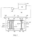
- FIG. 1 is a functional schematic diagram of an electronic chassis cooling system according to an exemplary embodiment of the present invention.
- the enclosure 100 includes a chassis 102, in which are mounted a plurality of electrical devices 104.
- a coolant fluid such as water
- the chassis 102 includes a fluid inlet 106, a fluid outlet 108, and one or more coolant flow passages 112 (only one illustrated) extending between the fluid inlet 106 and fluid outlet 108.
- a pump 114 or other equivalent device is used to impart flow energy to a coolant 113 stored in a coolant reservoir 115, causing the coolant to flow into and through the chassis 102.
- the chassis 102 As the coolant flows through the chassis 102, it absorbs the heat from the surrounding environment 116, as well as the heat generated by the electrical devices 104 when the devices 104 are energized. It will be appreciated that in some embodiments, such as the one depicted in FIG. 1, the chassis 102 may comprise one or more cold plates 117.
- the electrical devices 104 are implemented as a plurality of electronic circuit boards 104 (e.g., 104-1, 104-2, 104-3, . . . 104-N) that are thermally coupled to the cold plate 117. It will be appreciated that the electrical devices are not limited to those configured as electronic circuit boards 104, but could be configured, for example, as individual electronic components, electronic circuit packages, or one or more groups of individual components. Furthermore, it will be appreciated that the electrical devices 104 may be mounted in, and thermally coupled to, the chassis 102 using any one of numerous mounting and thermal coupling configurations.
- one of the electronic circuit boards 104 is configured as a primary control circuit 104-1, and another is configured as a backup control circuit 104-N.
- the primary control circuit 104-1 when properly energized and connected, is the primary control source for one or more non-illustrated external devices.
- the backup control circuit 104-N when properly energized and connected, is the backup control source for the one or more non-illustrated external devices, in the event the primary control circuit 104-1 becomes inoperable.
- the primary and backup control circuits 104-1, 104-N are each configured to automatically electrically shutdown if the circuit temperatures exceed a predetermined temperature.
- the primary and backup control circuits 104-1, 104-N include a primary control circuit temperature sensor 124-1 and a backup control circuit temperature sensor 124-N, respectively.
- the primary and backup control circuit temperature sensors 124-1, 124-N sense the temperature of at least a portion of the primary and backup control circuits 104-1, 104-N, respectively, and supply primary and backup control circuit temperature signals representative thereof.
- the primary control circuit 104-1 is responsive to the primary control circuit temperature signal to automatically electrically shutdown if the primary control circuit temperature signal indicates that primary control circuit temperature exceeds the predetermined temperature.
- the backup control circuit 104-N is responsive to the backup control circuit temperature signal to automatically electrically shutdown if the backup control circuit temperature signal indicates that backup control circuit temperature exceeds the predetermined temperature.
- FIG. 1 additionally depicts, a plurality of reservoirs 118 are formed in the chassis 102, and a phase change material (PCM) 122 is disposed within each reservoir 118.
- a PCM 122 is a material that absorbs significantly more heat during its change of phase, due to the latent heat of vaporization or fusion, than in its stable states. During the change of phase from one state to another (e.g., from a solid state to a liquid state, or vice-versa), a PCM 122 absorbs heat with little or no increase in the temperature of the material itself, and may therefore be used to passively cool and regulate the temperature of the electrical devices 104. It will be appreciated that the relative degree of cooling that the PCM 122 provides is dependent upon the amount of PCM 122 used, the type of PCM 122 used, and the placement of the PCM 122 within the chassis 102.
- PCM 122 As is also generally known, different types of PCM 122 change phase at different predetermined phase change temperatures. Hence, the temperature at which the passive cooling provided by a PCM 122 takes place can be selected by choosing the appropriate PCM 122.
- Various types of PCM 122 may be disposed within the reservoirs 118 and may include, for example, various paraffin waxes, and various salt hydrides. It will be appreciated that the particular PCM 122 that is selected may include not only a PCM 122 that transitions from a liquid phase to a solid phase and back to a liquid phase, such as a paraffin wax, but also a PCM 122, such as neopentyl glycol, which transitions from a first solid phase to a second solid phase.
- the reservoirs 118 are configured and located in the chassis 102, the PCM 122 is selected, and the coolant flow rate through the coolant flow passage 112 is provided, such that the coolant maintains the PCM 122 below the phase change temperature. It will be appreciated that the coolant flow rate through the flow passage 112 is additionally sufficient to maintain the primary and backup control circuits 104-1, 104-N below the above-mentioned predetermined temperature, as well as to sufficiently cool the remaining electrical devices 104-2, 104-3, ... 104-(N-1) mounted in the chassis 102.
- the PCM 122 will absorb the heat generated by the electrical devices 104 and from the surrounding environment, to sufficiently cool the electrical devices 104 for at least a period of time sufficient to implement a controlled shutdown.
- the reservoirs 118 are located, and the PCM 122 is selected, such that, if the flow of coolant ceases (or is otherwise inadequate) when at least the primary and backup control circuits 104-1, 104-N are energized, the backup control circuit 104-N will be maintained below its predetermined shutdown temperature for a longer period of time than the primary control circuit 104-1.
- the reservoirs 118 and PCM 122 are disposed such that the primary control circuit temperature will exceed the predetermined shutdown temperature within a first time period after the flow of coolant ceases, and the backup control circuit temperature will exceed the predetermined shutdown temperature a second time period, which is greater than the first time period, after the flow of coolant ceases.
- the backup control circuit 104-N will remain energized and operable for a period of time longer than the primary control circuit 104-1. It will be appreciated that the particular lengths of the first and second time periods may vary from system to system. It is seen that in the depicted embodiment this is accomplished by disposing additional reservoirs 118 and PCM 122 adjacent the backup control circuit 104-N. It will be appreciated, however, that this is merely exemplary of one methodology for implementing this function.
Landscapes
- Engineering & Computer Science (AREA)
- Aviation & Aerospace Engineering (AREA)
- Physics & Mathematics (AREA)
- Thermal Sciences (AREA)
- Microelectronics & Electronic Packaging (AREA)
- Cooling Or The Like Of Electrical Apparatus (AREA)
- Control Of Temperature (AREA)
Applications Claiming Priority (1)
| Application Number | Priority Date | Filing Date | Title |
|---|---|---|---|
| US11/544,175 US7433190B2 (en) | 2006-10-06 | 2006-10-06 | Liquid cooled electronic chassis having a plurality of phase change material reservoirs |
Publications (2)
| Publication Number | Publication Date |
|---|---|
| EP1909549A2 true EP1909549A2 (de) | 2008-04-09 |
| EP1909549A3 EP1909549A3 (de) | 2009-08-12 |
Family
ID=38895728
Family Applications (1)
| Application Number | Title | Priority Date | Filing Date |
|---|---|---|---|
| EP07117928A Withdrawn EP1909549A3 (de) | 2006-10-06 | 2007-10-04 | Elektronisches Fahrwerk mit mehreren Phasenwechselmaterialspeichern |
Country Status (2)
| Country | Link |
|---|---|
| US (1) | US7433190B2 (de) |
| EP (1) | EP1909549A3 (de) |
Cited By (3)
| Publication number | Priority date | Publication date | Assignee | Title |
|---|---|---|---|---|
| EP2568790A1 (de) * | 2011-09-06 | 2013-03-13 | ABB Research Ltd. | Vorrichtung und Verfahren |
| US9032743B2 (en) | 2011-09-06 | 2015-05-19 | Abb Research Ltd | Heat exchanger |
| EP3829282A1 (de) * | 2019-11-29 | 2021-06-02 | Ovh | Kühlvorrichtung zur montage auf einer wärmeerzeugenden komponente, kühlanordnung mit der kühlvorrichtung, kühlsystem mit der kühlvorrichtung und verfahren zur verwendung der kühlvorrichtung |
Families Citing this family (17)
| Publication number | Priority date | Publication date | Assignee | Title |
|---|---|---|---|---|
| DE102008004053A1 (de) * | 2008-01-11 | 2009-07-23 | Airbus Deutschland Gmbh | Spitzenlast-Kühlung von elektronischen Bauteilen durch phasenwechselnde Materialien |
| US20100242492A1 (en) * | 2009-03-30 | 2010-09-30 | Honeywell International Inc. | Distributed engine control systems and gas turbine engines |
| US20110024150A1 (en) * | 2009-07-31 | 2011-02-03 | General Electric Company | Cooling system and method for current carrying conductor |
| US9019704B2 (en) * | 2009-08-27 | 2015-04-28 | Hewlett-Packard Development Company, L.P. | Heat storage by phase-change material |
| US20130291368A1 (en) * | 2012-05-07 | 2013-11-07 | Niall Thomas Davidson | Cooled Part for Expansion Circuit Board Cooling |
| US9681589B1 (en) * | 2012-09-25 | 2017-06-13 | Amazon Technologies, Inc. | Phase change material-based data center cooling system |
| US9059130B2 (en) | 2012-12-31 | 2015-06-16 | International Business Machines Corporation | Phase changing on-chip thermal heat sink |
| WO2014137422A1 (en) * | 2013-03-08 | 2014-09-12 | Rolls-Royce North Americantechnologies, Inc. | Aircraft and system for supplying electrical power to an aircraft electrical load |
| US20150243428A1 (en) * | 2014-02-21 | 2015-08-27 | Varentec, Inc. | Methods and systems of field upgradeable transformers |
| GB2575679B (en) * | 2018-07-20 | 2022-06-15 | Bae Systems Plc | Thermal Management System |
| US20200100388A1 (en) * | 2018-09-25 | 2020-03-26 | Ge Aviation Systems Llc | Cold plate for power module |
| US20200109901A1 (en) | 2018-10-03 | 2020-04-09 | Raytheon Company | Additively manufactured thermal energy storage units |
| DE102020112968A1 (de) | 2020-05-13 | 2021-11-18 | Bayerische Motoren Werke Aktiengesellschaft | Elektronische Recheneinrichtung für ein Kraftfahrzeug sowie Kraftfahrzeug |
| US11531383B1 (en) | 2020-09-30 | 2022-12-20 | Amazon Technologies, Inc. | Mist cooling for computer systems |
| DE102023110946A1 (de) * | 2023-04-27 | 2024-10-31 | Bayerische Motoren Werke Aktiengesellschaft | Steuervorrichtung sowie Verfahren zum Kühlen von Steuergeräten |
| US12382607B1 (en) | 2023-05-02 | 2025-08-05 | Amazon Technologies, Inc. | Liquid immersion chassis liner |
| DE102024130008A1 (de) * | 2024-10-16 | 2026-04-16 | KSB SE & Co. KGaA | Pumpe, insbesondere Tauchpumpe, mit Kühlkörper zur Kühlung von Leistungsbauteilen |
Family Cites Families (25)
| Publication number | Priority date | Publication date | Assignee | Title |
|---|---|---|---|---|
| US4975803A (en) | 1988-12-07 | 1990-12-04 | Sundstrand Corporation | Cold plane system for cooling electronic circuit components |
| US5007478A (en) | 1989-05-26 | 1991-04-16 | University Of Miami | Microencapsulated phase change material slurry heat sinks |
| US5057968A (en) * | 1989-10-16 | 1991-10-15 | Lockheed Corporation | Cooling system for electronic modules |
| US5455458A (en) | 1993-08-09 | 1995-10-03 | Hughes Aircraft Company | Phase change cooling of semiconductor power modules |
| US6104611A (en) | 1995-10-05 | 2000-08-15 | Nortel Networks Corporation | Packaging system for thermally controlling the temperature of electronic equipment |
| US6169247B1 (en) * | 1998-06-11 | 2001-01-02 | Lucent Technologies Inc. | Enclosure for electronic components |
| US6307871B1 (en) * | 1998-09-11 | 2001-10-23 | Cutting Edge Optronics, Inc. | Laser system using phase change material for thermal control |
| US6260613B1 (en) | 1999-01-05 | 2001-07-17 | Intel Corporation | Transient cooling augmentation for electronic components |
| US6848500B1 (en) | 1999-03-11 | 2005-02-01 | Skyworks Solutions, Inc. | Cooling system for pulsed power electronics |
| US6261871B1 (en) | 1999-03-11 | 2001-07-17 | Conexant Systems, Inc. | Method and structure for temperature stabilization in flip chip technology |
| DE19945416C1 (de) * | 1999-09-22 | 2001-04-26 | Siemens Ag | Kühleinrichtung für einen Röntgenstrahler |
| US6239502B1 (en) | 1999-11-22 | 2001-05-29 | Bae Systems Controls | Phase change assisted heat sink |
| US6672370B2 (en) | 2000-03-14 | 2004-01-06 | Intel Corporation | Apparatus and method for passive phase change thermal management |
| US20030007328A1 (en) | 2000-03-16 | 2003-01-09 | Ulrich Fischer | Cooling device for electronic components |
| US6397618B1 (en) * | 2001-05-30 | 2002-06-04 | International Business Machines Corporation | Cooling system with auxiliary thermal buffer unit for cooling an electronics module |
| DE10157671A1 (de) | 2001-11-24 | 2003-06-05 | Merck Patent Gmbh | Optimierter Einsatz von PCM in Kühlvorrichtungen |
| US6609561B2 (en) | 2001-12-21 | 2003-08-26 | Intel Corporation | Tunnel-phase change heat exchanger |
| US7002800B2 (en) | 2002-01-25 | 2006-02-21 | Lockheed Martin Corporation | Integrated power and cooling architecture |
| US6621702B2 (en) * | 2002-01-25 | 2003-09-16 | Lockheed Martin Corporation | Method and apparatus for absorbing thermal energy |
| US20030202306A1 (en) | 2002-02-26 | 2003-10-30 | International Rectifier Corporation | Heat sink for semiconductor die employing phase change cooling |
| US6888720B2 (en) * | 2002-06-18 | 2005-05-03 | Sun Microsystems, Inc. | Distributed graphitic foam heat exchanger system |
| US6631755B1 (en) | 2002-07-17 | 2003-10-14 | Compal Electronics, Inc. | Thermal module with temporary heat storage |
| US6889755B2 (en) | 2003-02-18 | 2005-05-10 | Thermal Corp. | Heat pipe having a wick structure containing phase change materials |
| US7316262B1 (en) * | 2004-01-26 | 2008-01-08 | Rini Technologies, Inc. | Method and apparatus for absorbing thermal energy |
| US7327578B2 (en) * | 2004-02-06 | 2008-02-05 | Sun Microsystems, Inc. | Cooling failure mitigation for an electronics enclosure |
-
2006
- 2006-10-06 US US11/544,175 patent/US7433190B2/en not_active Expired - Fee Related
-
2007
- 2007-10-04 EP EP07117928A patent/EP1909549A3/de not_active Withdrawn
Cited By (5)
| Publication number | Priority date | Publication date | Assignee | Title |
|---|---|---|---|---|
| EP2568790A1 (de) * | 2011-09-06 | 2013-03-13 | ABB Research Ltd. | Vorrichtung und Verfahren |
| US9032743B2 (en) | 2011-09-06 | 2015-05-19 | Abb Research Ltd | Heat exchanger |
| EP3829282A1 (de) * | 2019-11-29 | 2021-06-02 | Ovh | Kühlvorrichtung zur montage auf einer wärmeerzeugenden komponente, kühlanordnung mit der kühlvorrichtung, kühlsystem mit der kühlvorrichtung und verfahren zur verwendung der kühlvorrichtung |
| US11406047B2 (en) | 2019-11-29 | 2022-08-02 | Ovh | Cooling systems adapted to be thermally connected to heat-generating equipment |
| US11937406B2 (en) | 2019-11-29 | 2024-03-19 | Ovh | Cooling system providing cooling to an infrastructure having a plurality of heat-generating units |
Also Published As
| Publication number | Publication date |
|---|---|
| EP1909549A3 (de) | 2009-08-12 |
| US7433190B2 (en) | 2008-10-07 |
| US20080084666A1 (en) | 2008-04-10 |
Similar Documents
| Publication | Publication Date | Title |
|---|---|---|
| US7433190B2 (en) | Liquid cooled electronic chassis having a plurality of phase change material reservoirs | |
| EP4068048B1 (de) | Systeme und verfahren zur autonom aktivierbaren redundanten kühlung einer wärmeerzeugungskomponente | |
| US12137536B2 (en) | Systems and methods for autonomously activable redundant cooling of a heat generating component | |
| US11729950B2 (en) | Immersion cooling system with dual dielectric cooling liquid circulation | |
| US6976528B1 (en) | Spray cooling system for extreme environments | |
| US10667427B2 (en) | Immersion cooling system for data centers | |
| CN110446396B (zh) | 用于数据中心的液体冷却系统 | |
| EP3829280B1 (de) | Kühlsysteme, die thermisch an wärmeerzeugende einrichtungen angeschlossen werden können | |
| US20020144811A1 (en) | Phase-change heat reservoir device for transient thermal management | |
| US20060151146A1 (en) | Phase-change heat reservoir device for transient thermal management | |
| US20070227710A1 (en) | Cooling system for electrical devices | |
| AU6117300A (en) | Thermal management apparatus for a sealed enclosure | |
| CN101950959A (zh) | 超导磁体的便携式磁体电源和从超导磁体去除能量的方法 | |
| EP3829278B1 (de) | Kühlanordnung für einen in einem serverrack montierbaren server | |
| CN109885148A (zh) | 缓解服务器液冷系统故障的方法及服务器的散热系统 | |
| US20250210454A1 (en) | Control unit | |
| US12595937B2 (en) | Thermal management apparatus | |
| EP2353349B1 (de) | Heizungssteuerung in einem funknetzknoten | |
| CA3170441C (en) | Circuit card assemblies | |
| EP4679956A1 (de) | Automatische durchflussregelung für kühlsysteme | |
| RU2319327C1 (ru) | Устройство для охлаждения электронных блоков | |
| Wilson et al. | A thermal bus system for cooling electronic components in high-density cabinets | |
| Yun et al. | COMET service module capillary pumped loop thermal control system test results | |
| Trichilo et al. | Thermal and Hydraulic Accommodation of Water Cooled Payloads in the Columbus APM | |
| Krasinski et al. | Development of the Pump and Flow Control Subassembly for the Space Station Photovoltaic Thermal Control |
Legal Events
| Date | Code | Title | Description |
|---|---|---|---|
| PUAI | Public reference made under article 153(3) epc to a published international application that has entered the european phase |
Free format text: ORIGINAL CODE: 0009012 |
|
| 17P | Request for examination filed |
Effective date: 20071005 |
|
| AK | Designated contracting states |
Kind code of ref document: A2 Designated state(s): AT BE BG CH CY CZ DE DK EE ES FI FR GB GR HU IE IS IT LI LT LU LV MC MT NL PL PT RO SE SI SK TR |
|
| AX | Request for extension of the european patent |
Extension state: AL BA HR MK RS |
|
| PUAL | Search report despatched |
Free format text: ORIGINAL CODE: 0009013 |
|
| STAA | Information on the status of an ep patent application or granted ep patent |
Free format text: STATUS: THE APPLICATION HAS BEEN WITHDRAWN |
|
| AK | Designated contracting states |
Kind code of ref document: A3 Designated state(s): AT BE BG CH CY CZ DE DK EE ES FI FR GB GR HU IE IS IT LI LT LU LV MC MT NL PL PT RO SE SI SK TR |
|
| AX | Request for extension of the european patent |
Extension state: AL BA HR MK RS |
|
| 18W | Application withdrawn |
Effective date: 20090724 |