EP1909276A2 - Optical-disc discriminating method and optical disc apparatus - Google Patents
Optical-disc discriminating method and optical disc apparatus Download PDFInfo
- Publication number
- EP1909276A2 EP1909276A2 EP07019021A EP07019021A EP1909276A2 EP 1909276 A2 EP1909276 A2 EP 1909276A2 EP 07019021 A EP07019021 A EP 07019021A EP 07019021 A EP07019021 A EP 07019021A EP 1909276 A2 EP1909276 A2 EP 1909276A2
- Authority
- EP
- European Patent Office
- Prior art keywords
- optical disc
- area
- record
- optical
- areas
- Prior art date
- Legal status (The legal status is an assumption and is not a legal conclusion. Google has not performed a legal analysis and makes no representation as to the accuracy of the status listed.)
- Granted
Links
- 230000003287 optical effect Effects 0.000 title claims abstract description 264
- 238000000034 method Methods 0.000 title claims description 33
- 239000010410 layer Substances 0.000 claims description 53
- 238000012545 processing Methods 0.000 claims description 34
- 239000011241 protective layer Substances 0.000 claims description 24
- 238000012850 discrimination method Methods 0.000 claims description 18
- 238000001514 detection method Methods 0.000 description 8
- 238000010586 diagram Methods 0.000 description 6
- 239000000470 constituent Substances 0.000 description 5
- 238000012937 correction Methods 0.000 description 5
- 239000011295 pitch Substances 0.000 description 5
- 230000015572 biosynthetic process Effects 0.000 description 4
- 230000002093 peripheral effect Effects 0.000 description 3
- 238000005755 formation reaction Methods 0.000 description 2
- 238000003786 synthesis reaction Methods 0.000 description 2
- 230000004075 alteration Effects 0.000 description 1
- 238000004590 computer program Methods 0.000 description 1
- 230000010485 coping Effects 0.000 description 1
- 230000007423 decrease Effects 0.000 description 1
- 238000003780 insertion Methods 0.000 description 1
- 230000037431 insertion Effects 0.000 description 1
- 238000011160 research Methods 0.000 description 1
- 238000012360 testing method Methods 0.000 description 1
Images


Classifications
-
- G—PHYSICS
- G11—INFORMATION STORAGE
- G11B—INFORMATION STORAGE BASED ON RELATIVE MOVEMENT BETWEEN RECORD CARRIER AND TRANSDUCER
- G11B19/00—Driving, starting, stopping record carriers not specifically of filamentary or web form, or of supports therefor; Control thereof; Control of operating function ; Driving both disc and head
- G11B19/02—Control of operating function, e.g. switching from recording to reproducing
- G11B19/12—Control of operating function, e.g. switching from recording to reproducing by sensing distinguishing features of or on records, e.g. diameter end mark
-
- G—PHYSICS
- G11—INFORMATION STORAGE
- G11B—INFORMATION STORAGE BASED ON RELATIVE MOVEMENT BETWEEN RECORD CARRIER AND TRANSDUCER
- G11B7/00—Recording or reproducing by optical means, e.g. recording using a thermal beam of optical radiation by modifying optical properties or the physical structure, reproducing using an optical beam at lower power by sensing optical properties; Record carriers therefor
- G11B2007/0003—Recording, reproducing or erasing systems characterised by the structure or type of the carrier
- G11B2007/0006—Recording, reproducing or erasing systems characterised by the structure or type of the carrier adapted for scanning different types of carrier, e.g. CD & DVD
Definitions
- the present invention relates to a method for discriminating the sorts of optical discs. Also, the invention relates to an optical disc apparatus which is furnished with a method for discriminating the sorts of optical discs.
- DVDs Digital Versatile Discs: multipurpose discs
- HD-DVD High Definition DVD: high density DVD
- optical disc apparatus each of which can record and reproduce information onto and from a plurality of sorts of optical discs by the single apparatus have been developed in large numbers, and the optical disc apparatus which copes with the two sorts of optical discs of the DVD and the HD-DVD has also been proposed. Besides, in such an optical disc apparatus coping with the plurality of sorts of optical discs, when the optical disc is inserted into the apparatus, the sort of the optical disc is first discriminated.
- the DVD and the HD-DVD are to be discriminated in accordance with the method stated in JP-A-2006-134367 , that is, on the basis of the generation timing of the S-shaped waveform of the FE signal, the generation timings of the S-shaped waveforms of the DVD and the HD-DVD become the same for the reason that both the thicknesses of transparent cover layers for protecting record layers are equal to be 0.6 mm, in the DVD and the HD-DVD. Accordingly, the discrimination between the DVD and the HD-DVD becomes difficult.
- the wavelengths of the light sources which are used for the DVD and the HD-DVD are different (for example, 650 nm for the DVD, and for example, 405 nm for the HD-DVD), and the optical disc apparatus which can record and reproduce information for the DVD and the HD-DVD has the problem that a long time is expended on the discrimination between the DVD and the HD-DVD.
- an object of the present invention is to provide an optical-disc discrimination method which can discriminate two sorts of optical discs without changing-over light sources, even when the thicknesses of protective layers for protecting record layers are equal.
- another object of the invention is to provide an optical disc apparatus to which such an optical-disc discrimination method is applied.
- the invention consists in an optical-disc discrimination method for discriminating a first optical disc which includes a record layer for recording data therein, and a protective layer for protecting the record layer, and in which the record layer has at least a first area and a second area that are formed at equal record densities; and a second optical disc which includes the record layer and the protective layer, and in which the record layer has at least a first area and a second area that are formed at different record densities; characterized by including the steps of projecting a light beam which has a wavelength for the first optical disc or for the second optical disc, onto respective areas of the first area and the second area, and detecting respective reflected lights which are reflected from the first area and the second area on the basis of the projections of the light beam, by a photodetection portion; executing predetermined processing for electric signals which are outputted from the photodetection portion; and discriminating whether an optical disc is the first optical disc or the second optical disc, on the basis of a result of the predetermined
- the two optical discs can be discriminated with only the light beam emitted from one light source, by utilizing the fact that the formations of the record densities in the first area and the second area are different between in the first optical disc and in the second optical disc. Therefore, even when the thicknesses of the protective layers for protecting the record layers are equal, the discrimination between the first optical disc and the second optical disc can be accurately performed without changing-over light sources.
- the invention may well consist in the optical-disc discrimination method of the above configuration, wherein thicknesses of the protective layers of the first optical disc and the second optical disc are equal; and the first areas are data areas in which data are recorded, and the second areas are lead-in areas in which management information items for managing the data areas are recorded.
- the configuration of the first optical disc corresponds to that of a DVD
- the configuration of the second optical disc corresponds to that of an HD-DVD.
- the invention may well consist in the optical-disc discrimination method of the above configuration, wherein the predetermined processing is a process which obtains an amplitude of a tracking error signal; and the sort of the optical disc is discriminated by comparing the amplitude of the tracking error signal in the first area and the amplitude of the tracking error signal in the second area.
- this method using a configuration which has heretofore been included in an optical disc apparatus, it is permitted to provide a discrimination method which can accurately discriminate the first optical disc and the second optical disc without changing-over light sources, even when the thicknesses of the protective layers for protecting the record layers are equal.
- the invention may well consist in the optical-disc discrimination method of the above configuration, wherein the record density of the first area of the second optical disc is formed to be higher than that of the second area of the second optical disc, and the record density of the second area of the second optical disc is formed to be substantially equal to those of the first and second areas of the first optical disc; the light beam which is projected onto the respective areas of the first area and the second area is a light beam of a wavelength for use in reproduction of the first optical disc; and the predetermined processing is a process which permits a judgment on whether or not read of information is possible, as to each of the first area and the second area.
- the invention consists in an optical disc apparatus including a plurality of light sources which emit light beams of different wavelengths, respectively; an objective which condenses the light beam emitted from the light source, onto a record layer of an optical disc; a photodetection portion which receives reflected light reflected from the record layer; and a disc discrimination portion which discriminates the optical disc inserted into the apparatus; characterized in that the apparatus is configured so as to be capable of reproduction or record and reproduction of a first optical disc which includes a record layer for recording data therein, and a protective layer for protecting the record layer, and in which the record layer has at least a first area and a second area that are formed at equal record densities; and a second optical disc which includes the record layer and the protective layer, and in which the record layer has at least a first area and a second area that are formed at different record densities; and that the disc discrimination portion executes predetermined processing for electric signals which are obtained by the photodetection portion when the light
- the optical disc inserted into the optical disc apparatus is the first optical disc or the second optical disc can be discriminated with only the light beam emitted from one light source, by utilizing the fact that the formations of the record densities in the first area and the second area are different between in the first optical disc and in the second optical disc. Therefore, even when the thicknesses of the protective layers for protecting the record layers are equal, it is permitted to provide an optical disc apparatus in which the discrimination between the first optical disc and the second optical disc can be accurately performed without changing-over light sources.
- the invention may well consist in the optical disc apparatus of the above configuration, wherein thicknesses of the protective layers of the first optical disc and the second optical disc are equal; and the first areas are data areas in which data are recorded, and the second areas are lead-in areas in which management information items for managing the data areas are recorded.
- the configuration of the first optical disc corresponds to that of a DVD
- the configuration of the second optical disc corresponds to that of an HD-DVD.
- the invention may well consist in the optical disc apparatus of the above configuration, wherein the predetermined processing is a process which obtains an amplitude of a tracking error signal; and the sort of the optical disc is discriminated by comparing the amplitude of the tracking error signal in the first area and the amplitude of the tracking error signal in the second area.
- the predetermined processing is a process which obtains an amplitude of a tracking error signal
- the sort of the optical disc is discriminated by comparing the amplitude of the tracking error signal in the first area and the amplitude of the tracking error signal in the second area.
- this apparatus using a configuration which has heretofore been included in an optical disc apparatus, it is possible to realize a configuration which can accurately discriminate the first optical disc and the second optical disc without changing-over light sources, even when the thicknesses of the protective layers for protecting the record layers are equal.
- the invention may well consist in the optical disc apparatus of the above configuration, wherein the record density of the first area of the second optical disc is formed to be higher than that of the second area of the second optical disc, and the record density of the second area of the second optical disc is formed to be substantially equal to those of the first and second areas of the first optical disc; the light beam which is projected onto the respective areas of the first area and the second area is a light beam of a wavelength for use in reproduction of the first optical disc; and the predetermined processing is a process which permits a judgment on whether or not read of information is possible, as to each of the first area and the second area.
- Fig. 1 is a block diagram showing the configuration of the optical disc apparatus 1 of the first embodiment.
- the optical disc apparatus 1 is configured so as to be capable of reproducing the information of an optical disc 14 and recording information onto the optical disc 14.
- the sorts of the optical discs 14 onto and from which the optical disc apparatus 1 can record and reproduce the information are a DVD and an HD-DVD.
- Numeral 2 designates a spindle motor, and the optical disc 14 is detachably held by a chuck portion (not shown) which is disposed at the upper part of the spindle motor 2. Besides, in performing the record or reproduction of the information of the optical disc 14, the spindle motor 2 rotates the optical disc 14 continuously. The rotational control of the spindle motor 2 is performed by a spindle motor control portion 3.
- Numeral 4 designates an optical pickup, by which a laser beam emitted from a light source is projected onto the optical disc 14 so as to permit the write of the information into the optical disc 14 or the read of the information recorded on the optical disc 14.
- Fig. 2 is a schematic diagram showing the optical system of the optical pickup 4.
- the optical pickup 4 includes a first light source 21, a second light source 22, a color synthesis prism 23, a collimate lens 24, a beam splitter 25, an objective 26, a condensing lens 28 and a photodetector 29.
- the configuration of the optical system constituting the optical pickup is not restricted to the illustrated one, but various alterations are, of course, possible.
- Both the first light source 21 and the second light source 22 are laser diodes (LDs).
- the first light source 21 is a light source corresponding to the HD-DVD, and it emits a laser beam of a wavelength band of, for example, 405 nm.
- the second light source 22 is a light source corresponding to the DVD, and it emits a laser beam of a wavelength band of, for example, 650 nm.
- the light beams emitted from the light sources 21 and 22 have their optic axes made identical by the color synthesis prism 23, and they are made a collimated beam by the collimate lens 24.
- the collimated beam is transmitted through the beam splitter 25, and it is condensed by the objective 26 onto a record layer 14a in which the information of the optical disc 14 is recorded.
- Reflected light reflected from the record layer 14a is passed through the objective 26, it is reflected by the beam splitter 25, and it is condensed onto the light receiving portion of the photodetector 29 by the condensing lens 28.
- the photodetector 29 converts optical information which the received light beam has, into an electric signal.
- a slide motor control portion 5 controls the drive of a slide motor, not shown, which is disposed so as to make the optical pickup 4 movable. Thus, the movement of the optical pickup 4 in the radial direction thereof is controlled.
- An RF signal processing portion 6 processes an RF signal obtained by the photodetector 29 of the optical pickup 4, and feeds the processed signal to a demodulation portion 7.
- the demodulation portion 7 demodulates data, and detects the error of the data. In a case where the error has been detected and where it is correctable, the demodulation portion 7 performs the correction process of the data and feeds the reproduced data to an interface portion 8. By the way, in a case where the reproduction error for which the correction process is impossible has occurred, the retry of the data is executed by a well-known method. Besides, the demodulation portion 7 plays the role of feeding a general control portion 13 with an error rate which is the occurrence proportion of the read errors of the data.
- the interface portion 8 outputs the reproduced data fed from the demodulation portion 7, to a personal computer or the like external equipment not shown.
- a focus error signal processing portion 9 generates a focus error signal by using signals detected by the photodetector 29 of the optical pickup 4.
- Fig. 3 is a plan view showing the configuration of the detection surfaces of the photodetector 29. Incidentally, Fig. 3 is the view seen from the side of the condensing lens 28.
- the photodetector 29 has the detection surfaces A, B, C and D quartered as shown in Fig. 3, and the focus error signal processing portion 9 generates the focus error signal on the basis of the difference [(A + C) - (B + D)] of the diagonal sums of the detection signals from the respective detection surfaces A-D.
- the focus error signal generated by the focus error signal processing portion 9 is fed to an actuator control portion 11.
- a tracking error signal processing portion 10 generates a tracking error signal by using the signals detected by the photodetector 29 of the optical pickup 4.
- the tracking error signal is generated on the basis of the difference [(A + B) - (C + D)] of the lateral sums of the detection signals from the respective detection surfaces A - D (refer to Fig. 3).
- the tracking error signal generated by the tracking error signal processing portion 10 is fed to the actuator control portion 11.
- the tracking error signal generated by the tracking error signal processing portion 10 is fed to a disc discrimination portion 15 when the sort of the optical disc 14 is discriminated.
- the disc discrimination portion 15 discriminates whether the optical disc 14 inserted into the optical disc apparatus 1 is the DVD or the HD-DVD, on the basis of the amplitude of the tracking error signal. The details of the discrimination method for the optical disc 14, in the disc discrimination portion 15, will be stated later.
- this embodiment has been so configured that the focus error signal and the tracking error signal are obtained by quartering the detection surfaces of the photodetector 29.
- the configuration for obtaining the focus error signal and the tracking error signal is not restricted to the illustrated one, but it can be variously altered within a scope not departing from the objects of the invention.
- it is also allowed to adopt a configuration in which the focus error signal is obtained by a so-called “spot size method", while the tracking error signal is obtained by a so-called "correct far field method”.
- the actuator control portion 11 feeds a drive signal to an actuator 27 on which the objective 26 is mounted (refer to Fig. 2 as to the constituents 26 and 27), on the basis of the signals sent from the focus error signal processing portion 9 and the tracking error signal processing portion 10.
- the actuator 27 fed with the drive signal actuates the respective portions on the basis of the signals, thereby to perform a focus control in which the objective 26 is moved in a focusing direction parallel to the direction of the optic axis thereof, so as to be focused, and a tracking control in which the objective 26 is moved in a direction parallel to the radial direction of the optical disc 14, so as to bring the spot position of the laser beam into agreement with the position of a track formed in the optical disc 14.
- the actuator control portion 11 controls the movements of the objective 27 also in the case of discriminating the sort of the optical disc 14 inserted into the optical disc apparatus 1, in the case of performing the pull-in operation of focusing, etc.
- the general control portion 13 controls the spindle motor control portion 3, the slide motor control portion 5, the RF signal processing portion 6, the demodulation portion 7, the interface portion 8, the focus error signal processing portion 9, the tracking error signal processing portion 10, the actuator control portion 11, and a storage portion 12 for storing information necessary for the controls, thereby to control the whole apparatus.
- Fig. 4 is a schematic plan view showing a configurational example of the record layer 14a of the optical disc 14.
- the record layer 14a of the optical disc 14 is formed with a lead-in area 31 which exists on an inner peripheral side, a data area 32 which exists on the outer peripheral side of the lead-in area 31, and a lead-out area 33 which exists on the outer peripheral side of the data area 32.
- a protective layer 14b (refer to Fig. 2) which protects the record layer 14a is provided on the surface of the record layer 14a of the optical disc 14 in a manner to cover the record layer 14a, and the thicknesses of such protective layers 14b are equal between the DVD and the HD-DVD.
- Management information for managing the information of the optical disc 14 or the data area 32, and so forth are recorded in the lead-in area 31.
- Data which chiefly become subjects for the reproduction and run such as video data, audio data, content data and a computer program, are recorded in the data area 32.
- the lead-out area 33 is an area which indicates the end of the data area 32, and in which information is not especially recorded.
- the lead-in area 31 and the data area 32 are formed at the same record density (in both the areas, the shortest mark length is 0.4 ⁇ m, and a track pitch is 0.74 ⁇ m).
- the lead-in area 31 and the data area 32 have different record densities, and the lead-in area 31 is formed at a low record density (the shortest mark length is 0.408 ⁇ m, and a track pitch is 0.68 ⁇ m), while the data area 32 is formed at a high record density (the shortest mark length is 0.18 ⁇ m, and a track pitch is 0.34 ⁇ m).
- the DVD and the HD-DVD in which the thicknesses of the protective layers 14b for protecting the record layers 14a are equal are discriminated by utilizing the fact that the relationships of the record densities of the lead-in areas 31 and the data areas 32 are different between the DVD and the HD-DVD.
- the optical disc apparatus 1 whether the optical disc 14 inserted into the optical disc apparatus 1 is the DVD or the HD-DVD is discriminated by a method as stated below.
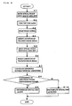
- Fig. 5 is a flow chart showing a procedure which discriminates the sort of the optical disc 14 in the optical disc apparatus 1. Now, the discrimination of the optical disc 14 in the optical disc apparatus 1 will be described in accordance with the flow chart of Fig. 5.
- the optical pickup 4 When the optical disc 14 is inserted into the optical disc apparatus 1, the optical pickup 4 is moved to a predetermined position on the side of the lead-in area 31 (refer to Fig. 4) by the slide motor, not shown, which is controlled by the slide motor control portion 5 (regarding the constituents 4 and 5, refer to Fig. 1) (step S1).
- the second light source 22 (the LD for the DVD) included in the optical pickup 4 is turned “ON”, and a laser beam is emitted (step S2).
- the laser beam emitted here is projected onto the lead-in area 31 of the optical disc 14.
- the procedure is configured here so as to turn “ON” the second light source 22, it may well be configured so as to turn “ON” the first light source 21 (the LD for the HD-DVD).
- the actuator 27 on which the objective 26 is mounted (regarding the constituents 26 and 27, refer to Fig. 2) is moved by the control of the actuator control portion 11, and the laser beam is focused on the record layer 14a of the optical disc 14, whereby the focus control is started (step S3).
- the tracking error signal of one revolution cycle of the optical disc 14 as depends upon only the eccentricity of the optical disc 14 is generated, and the amplitude of the tracking error signal is detected by the disc discrimination portion 15 (refer to Fig. 1) (step S4).
- the amplitude of the tracking error signal detected here is stored in the storage portion 12.
- the procedure here is configured so as to obtain the tracking error signal by utilizing the fact that the laser beam projected onto the record layer 14a of the optical disc 14 crosses the track of the optical disc 14 on account of the eccentricity which occurs due to the deviation between the center of the optical disc 14 and the rotational axis of the spindle motor 2 (refer to Fig. 1). Since, however, the nonexistence of the eccentricity is possible, it is also allowed to adopt, for example, a configuration in which a predetermined vibration is imparted to the objective 26 by the actuator 27 so that the objective 26 may vibrate in a tracking direction (a direction parallel to the radial direction of the optical disc 14).
- the optical pickup 4 When the amplitude of the tracking error signal in the lead-in area 31 is detected, the optical pickup 4 is moved to a predetermined position on the side of the data area 32 (refer to Fig. 4) by the slide motor (step S5). When the optical pickup 4 is moved to the predetermined position, the laser beam is projected onto the data area 32. Then, in the state where the tracking control is not performed, the tracking error signal of one revolution cycle of the optical disc 14 as depends upon only the eccentricity of the optical disc 14 is generated, and the amplitude of the tracking error signal is detected by the disc discrimination portion 15 (step S6). The amplitude of the tracking error signal detected here is stored in the storage portion 12. By the way, in a time period after the step S4 and till the execution of the step S6, the second light source 22 is held turned “ON", and also the focus control is being performed.
- step S7 the difference between the amplitude of the tracking error signal detected in the lead-in area 31 and that of the tracking error signal detected in the data area 32 is calculated in the disc discrimination portion 15 (step S7). Whether or not the calculated difference between the amplitudes of the tracking error signals is within a predetermined range, is checked (step S8).
- the magnitude of the amplitude of the tracking error signal has a relation to track pitches which are formed in the record layer 14a of the optical disc 14.
- the magnitude of the amplitude of the tracking error signal decreases. That is, when the record density of the record layer 14a of the optical disc 14 heightens, the amplitude of the tracking error signal becomes small.
- the amplitudes of the tracking error signals become the same.
- the amplitude of the tracking error signal obtained in the lead-in area 31 becomes larger than that of the tracking error signal obtained in the data area 32.
- the predetermined range at the step S8 is determined as a range value with which the lead-in area 31 and the data area 32 can be regarded as having the equal record densities, it is permitted to discriminate the DVD and the HD-DVD in accordance with the difference between the amplitudes of the tracking error signals.
- the optical disc 14 is discriminated as the DVD (step S9).
- the record densities are regarded as being different between in the lead-in area 31 and in the data area 32, and hence, the optical disc 14 is discriminated as the HD-DVD (step S10).
- the amplitude values of the tracking error signals change to some extent also on account of the fact that the reflection factors of the record layers 14a of the optical discs 14 change depending upon the difference of data record states in the record layers 14a (depending upon, for example, whether or not data are recorded), though the changes of the amplitude values attributed to the difference of the reflection factors are very small as compared with the changes of the amplitude values of the tracking errors attributed to the difference of the record densities as stated above. Therefore, in determining the above predetermined range, it may be determined in anticipation of a difference occurring on account of the different data record states.
- FIG. 6 is a block diagram showing the configuration of the optical disc apparatus 51 of the second embodiment. Also the optical disc apparatus 51 is capable of recording and reproducing information onto and from a DVD and an HD-DVD just like the optical disc apparatus 1 of the first embodiment.
- portions which correspond to those of the optical disc apparatus 1 of the first embodiment will be assigned the same reference numerals, and the description thereof shall be omitted unless especially required.
- the disc discrimination portion 15 has received information on a tracking error signal obtained by the tracking error signal processing portion 10.
- a disc discrimination portion 15 is so configured that the information from the tracking error signal processing portion 10 is not received, but that information from a demodulation portion 7 is received, thereby to discriminate the sort of an optical disc 14. This point will be described below.
- the demodulation portion 7 demodulates data and detects the error of the data. In a case where the error has been detected and where it is correctable, the demodulation portion 7 performs the correction process of the data and feeds the reproduced data to an interface portion 8. By the way, in a case where the reproduction error for which the correction process is impossible has occurred, the retry of the data is executed by a well-known method. Besides, the demodulation portion 7 plays the role of feeding a general control portion 13 with an error rate which is the occurrence proportion of the read errors of the data.
- the demodulation portion 7 is configured so as to feed the error rate to the disc discrimination portion 15, in discriminating the sort of the optical disc 14.
- the error rate is sometimes unobtainable as in a case where the reproduction error for which the correction of the data is impossible has appeared.
- the error rate is assumed to be, for example, 100%, and it is fed as a predetermined error rate.
- the disc discrimination portion 15 discriminates the sort of the optical disc 14 (whether the optical disc 14 is the DVD or the HD-DVD) on the basis of the data fed from the demodulation portion 7. This will be described in conjunction with a flow chart shown in Fig. 7. Incidentally, Fig. 7 is the flow chart showing a procedure which discriminates the sort of the optical disc 14 in the optical disc apparatus 51.
- an optical pickup 4 is moved to a predetermined position on the side of a lead-in area 31 (refer to Fig. 4) by a slide motor, not shown, which is controlled by a slide motor control portion 5 (regarding the constituents 4 and 5, refer to Fig. 6) (step S11).
- a second light source 22 an LD for the DVD included in the optical pickup 4 is turned “ON”, and a laser beam is emitted (step S12). The laser beam emitted here is projected onto the lead-in area 31 of the optical disc 14.
- an actuator 27 on which an objective 26 is mounted (regarding the constituents 26 and 27, refer to Fig. 2) is moved by the control of an actuator control portion 11, and the laser beam is focused on the record layer 14a of the optical disc 14, whereby a focus control is started (step S13). Subsequently, a tracking control is also started (step S14).
- the collection of a reproduction (RF) signal is started, the error rate is fed from the demodulation portion 7 to the disc discrimination portion 15, and the disc discrimination portion 15 judges whether or not the read of the data is possible, in accordance with the information of the error rate (step S 15).
- the data is judged readable in a case where the value of the error rate is, at most, a predetermined value set by performing tests beforehand, and the data is judged unreadable in a case where the error rate is larger than the predetermined value.
- a time period for collecting the reproduction signal of the optical disc 14 may be a short time in which whether or not the read of the data is possible can be judged.
- the lead-in areas 31 of the DVD and the HD-DVD are somewhat different in record densities, they are formed at the nearly equal record densities. Therefore, in the case where the laser beam for the DVD has been projected, the data of both the optical discs are judged readable (that is, the error rates become, at most, the predetermined value). For this reason, in a case where either of the DVD and the HD-DVD is inserted into the optical disc apparatus 51, it does not occur as a general rule that the data becomes unreadable at the step S14. However, the read of the data is sometimes judged impossible on account of the flaw, the stain or the like of the optical disc 14 or the insertion of an optical disc which is neither the DVD nor the HD-DVD, into the optical disc apparatus 51. In such a case, the optical disc 14 is ejected from the optical disc apparatus 51 (step S16).
- the optical disc 14 is ejected from the optical disc apparatus 51 as soon as the read of the data has been judged impossible at the step S15, it is also allowed to adopt, for example, a configuration in which the position of the optical pickup 4 is moved to a plurality ofpositions within the lead-in area 31, and the optical disc 14 is ejected out of the optical disc apparatus 51 only in a case where the read of the data has been judged impossible at all the positions.
- the optical pickup 4 is moved to a predetermined position on the side of a data area 32 (refer to Fig. 4) by the slide motor (step S 17).
- the collection of a reproduction (RF) signal is started, the error rate is fed from the demodulation portion 7 to the disc discrimination portion 15, and the disc discrimination portion 15 judges whether or not the read of the data is possible, in accordance with the information of the error rate (step S18).
- a time period for collecting the reproduction signal may be a short time in which whether or not the read of the data is possible can be judged.
- the laser beam for the DVD is projected onto the optical disc 14. Therefore, in a case where the DVD is inserted into the optical disc apparatus 51, the error rate becomes, at most, the predetermined value, and the read of the data is judged possible.
- the data area 32 is configured at a higher record density than in the DVD, and hence, the error rate becomes extraordinarily high under the influence of inter-symbol interference. Consequently, the error rate becomes larger than the predetermined value, and the read of the data is judged impossible.
- the data of the optical disc 14 inserted into the optical disc apparatus 51 are readable in both the lead-in area 31 and the data area 32. Therefore, the record densities of the lead-in area 31 and the data area 32 are judged equal, and the optical disc 14 is discriminated as the DVD (step S19).
- the optical disc 14 inserted into the optical disc apparatus 51 is judged as having different record densities in the lead-in area 31 and the data area 32, and it is discriminated as the HD-DVD (step S20).
- the optical disc apparatuses have been configured so as to record and reproduce information onto and from only the DVD and the HD-DVD.
- the optical disc apparatuses are not restrictive, but an optical disc apparatus capable of recording and reproducing information also onto and from a CD, a BD (Blu-ray Disc), etc. may well be configured.
- it is also allowed to adopt, for example, a configuration in which the invention is applied to the discrimination between the DVD and the HD-DVD, and in which the generation timing of the S-shaped waveform of a focus error signal is employed for discriminating the other discs.
- the invention is, of course, applicable to a reproduction-only optical disc apparatus.
- the invention is applied to the discrimination between the DVD and the HD-DVD in the existing standards.
- this aspect is not restrictive, but the invention is applicable to the discrimination between optical discs one of which has equal record densities in all the areas of a record layer and the other of which has two sorts of areas of different record densities, as in the DVD and the HD-DVD.
Landscapes
- Optical Recording Or Reproduction (AREA)
Abstract
Description
- The present invention relates to a method for discriminating the sorts of optical discs. Also, the invention relates to an optical disc apparatus which is furnished with a method for discriminating the sorts of optical discs.
- In late years, DVDs (Digital Versatile Discs: multipurpose discs) have come into wide use. Recently, in order to further increase the information quantity of an optical disc, researches on the higher density of the optical disc have been made, and an optical disc heightened in density, such as HD-DVD (High Definition DVD: high density DVD), has also appeared.
- The record and reproduction of the information of an optical disc are performed in an optical disc apparatus. Optical disc apparatuses each of which can record and reproduce information onto and from a plurality of sorts of optical discs by the single apparatus have been developed in large numbers, and the optical disc apparatus which copes with the two sorts of optical discs of the DVD and the HD-DVD has also been proposed. Besides, in such an optical disc apparatus coping with the plurality of sorts of optical discs, when the optical disc is inserted into the apparatus, the sort of the optical disc is first discriminated.
- Various methods have heretofore been proposed as methods for discriminating the sorts of the optical discs, and they are, for example, discrimination methods introduced in
JP-A-2006-134367 JP-A-2000-311357 - However, when the DVD and the HD-DVD are to be discriminated in accordance with the method stated in
JP-A-2006-134367 - Besides, in the configuration wherein the optical discs are discriminated by utilizing the magnitude of the amplitude of the S-shaped waveform as stated in
JP-A-2006-134367 JP-A-2000-311357 - In view of the above problems, an object of the present invention is to provide an optical-disc discrimination method which can discriminate two sorts of optical discs without changing-over light sources, even when the thicknesses of protective layers for protecting record layers are equal. Besides, another object of the invention is to provide an optical disc apparatus to which such an optical-disc discrimination method is applied.
- In order to accomplish the objects, the invention consists in an optical-disc discrimination method for discriminating a first optical disc which includes a record layer for recording data therein, and a protective layer for protecting the record layer, and in which the record layer has at least a first area and a second area that are formed at equal record densities; and a second optical disc which includes the record layer and the protective layer, and in which the record layer has at least a first area and a second area that are formed at different record densities; characterized by including the steps of projecting a light beam which has a wavelength for the first optical disc or for the second optical disc, onto respective areas of the first area and the second area, and detecting respective reflected lights which are reflected from the first area and the second area on the basis of the projections of the light beam, by a photodetection portion; executing predetermined processing for electric signals which are outputted from the photodetection portion; and discriminating whether an optical disc is the first optical disc or the second optical disc, on the basis of a result of the predetermined processing for the reflected light from the first area, and a result of the predetermined processing for the reflected light from the second area.
- According to this method, the two optical discs can be discriminated with only the light beam emitted from one light source, by utilizing the fact that the formations of the record densities in the first area and the second area are different between in the first optical disc and in the second optical disc. Therefore, even when the thicknesses of the protective layers for protecting the record layers are equal, the discrimination between the first optical disc and the second optical disc can be accurately performed without changing-over light sources.
- Besides, the invention may well consist in the optical-disc discrimination method of the above configuration, wherein thicknesses of the protective layers of the first optical disc and the second optical disc are equal; and the first areas are data areas in which data are recorded, and the second areas are lead-in areas in which management information items for managing the data areas are recorded.
- In the existing standards, the configuration of the first optical disc corresponds to that of a DVD, and the configuration of the second optical disc corresponds to that of an HD-DVD. In accordance with this configuration, accordingly, the discrimination between the HD-DVD and the DVD in which the thicknesses of the protective layers for protecting the record layers are equal can be accurately performed without changing-over light sources.
- Besides, the invention may well consist in the optical-disc discrimination method of the above configuration, wherein the predetermined processing is a process which obtains an amplitude of a tracking error signal; and the sort of the optical disc is discriminated by comparing the amplitude of the tracking error signal in the first area and the amplitude of the tracking error signal in the second area.
- According to this method, using a configuration which has heretofore been included in an optical disc apparatus, it is permitted to provide a discrimination method which can accurately discriminate the first optical disc and the second optical disc without changing-over light sources, even when the thicknesses of the protective layers for protecting the record layers are equal.
- Besides, the invention may well consist in the optical-disc discrimination method of the above configuration, wherein the record density of the first area of the second optical disc is formed to be higher than that of the second area of the second optical disc, and the record density of the second area of the second optical disc is formed to be substantially equal to those of the first and second areas of the first optical disc; the light beam which is projected onto the respective areas of the first area and the second area is a light beam of a wavelength for use in reproduction of the first optical disc; and the predetermined processing is a process which permits a judgment on whether or not read of information is possible, as to each of the first area and the second area.
- Also in the case of this configuration, using a configuration which has heretofore been included in an optical disc apparatus, it is permitted to provide a discrimination method which can accurately discriminate the first optical disc and the second optical disc without changing-over light sources, even when the thicknesses of the protective layers for protecting the record layers are equal.
- Besides, in order to accomplish the objects, the invention consists in an optical disc apparatus including a plurality of light sources which emit light beams of different wavelengths, respectively; an objective which condenses the light beam emitted from the light source, onto a record layer of an optical disc; a photodetection portion which receives reflected light reflected from the record layer; and a disc discrimination portion which discriminates the optical disc inserted into the apparatus; characterized in that the apparatus is configured so as to be capable of reproduction or record and reproduction of a first optical disc which includes a record layer for recording data therein, and a protective layer for protecting the record layer, and in which the record layer has at least a first area and a second area that are formed at equal record densities; and a second optical disc which includes the record layer and the protective layer, and in which the record layer has at least a first area and a second area that are formed at different record densities; and that the disc discrimination portion executes predetermined processing for electric signals which are obtained by the photodetection portion when the light beam having the wavelength for the first optical disc or for the second optical disc has been projected from the light source onto respective areas of the first area and the second area, whereupon it performs the discrimination between the first optical disc and the second optical disc, on the basis of a result of the predetermined processing for the reflected light from the first area, and a result of the predetermined processing for the reflected light from the second area.
- According to this apparatus, whether or not the optical disc inserted into the optical disc apparatus is the first optical disc or the second optical disc can be discriminated with only the light beam emitted from one light source, by utilizing the fact that the formations of the record densities in the first area and the second area are different between in the first optical disc and in the second optical disc. Therefore, even when the thicknesses of the protective layers for protecting the record layers are equal, it is permitted to provide an optical disc apparatus in which the discrimination between the first optical disc and the second optical disc can be accurately performed without changing-over light sources.
- Besides, the invention may well consist in the optical disc apparatus of the above configuration, wherein thicknesses of the protective layers of the first optical disc and the second optical disc are equal; and the first areas are data areas in which data are recorded, and the second areas are lead-in areas in which management information items for managing the data areas are recorded.
- In the existing standards, the configuration of the first optical disc corresponds to that of a DVD, and the configuration of the second optical disc corresponds to that of an HD-DVD. In accordance with this configuration, accordingly, it is permitted to provide an optical disc apparatus which can accurately perform the discrimination between the HD-DVD and the DVD where the thicknesses of the protective layers for protecting the record layers are equal, without changing-over light sources.
- Besides, the invention may well consist in the optical disc apparatus of the above configuration, wherein the predetermined processing is a process which obtains an amplitude of a tracking error signal; and the sort of the optical disc is discriminated by comparing the amplitude of the tracking error signal in the first area and the amplitude of the tracking error signal in the second area.
- According to this apparatus, using a configuration which has heretofore been included in an optical disc apparatus, it is possible to realize a configuration which can accurately discriminate the first optical disc and the second optical disc without changing-over light sources, even when the thicknesses of the protective layers for protecting the record layers are equal.
- Besides, the invention may well consist in the optical disc apparatus of the above configuration, wherein the record density of the first area of the second optical disc is formed to be higher than that of the second area of the second optical disc, and the record density of the second area of the second optical disc is formed to be substantially equal to those of the first and second areas of the first optical disc; the light beam which is projected onto the respective areas of the first area and the second area is a light beam of a wavelength for use in reproduction of the first optical disc; and the predetermined processing is a process which permits a judgment on whether or not read of information is possible, as to each of the first area and the second area.
- Also in the case of this configuration, using a configuration which has heretofore been included in an optical disc apparatus, it is possible to realize a configuration which can accurately discriminate the first optical disc and the second optical disc without changing-over light sources, even when the thicknesses of the protective layers for protecting the record layers are equal.
-
- Fig. 1 is a block diagram showing the configuration of the optical disc apparatus of a first embodiment to which the optical-disc discrimination method of the present invention is applied;
- Fig. 2 is a schematic diagram showing the configuration of the optical system of an optical pickup which is included in the optical disc apparatus of the first embodiment;
- Fig. 3 is a plan view showing the configuration of the detection surfaces of a photodetector which is included in the optical pickup in the first embodiment;
- Fig. 4 is a schematic plan view showing a configurational example of the record layer of an optical disc which can be recorded and reproduced by the optical disc apparatus of the first embodiment;
- Fig. 5 is a flow chart showing a procedure which discriminates the sort of an optical disc in the optical disc apparatus of the first embodiment;
- Fig. 6 is a block diagram showing the configuration of the optical disc apparatus of a second embodiment to which the optical-disc discrimination method of the invention is applied; and
- Fig. 7 is a flow chart showing a procedure which discriminates the sort of an optical disc in the optical disc apparatus of the second embodiment.
- While the contents of the present invention will now be described in detail, embodiments stated here are mere examples, and the invention shall not be restricted the embodiments.
- First, there will be described the optical disc apparatus of a first embodiment to which the optical-disc discrimination method of the invention is applied. Fig. 1 is a block diagram showing the configuration of the
optical disc apparatus 1 of the first embodiment. Theoptical disc apparatus 1 is configured so as to be capable of reproducing the information of anoptical disc 14 and recording information onto theoptical disc 14. Incidentally, the sorts of theoptical discs 14 onto and from which theoptical disc apparatus 1 can record and reproduce the information are a DVD and an HD-DVD. -
Numeral 2 designates a spindle motor, and theoptical disc 14 is detachably held by a chuck portion (not shown) which is disposed at the upper part of thespindle motor 2. Besides, in performing the record or reproduction of the information of theoptical disc 14, thespindle motor 2 rotates theoptical disc 14 continuously. The rotational control of thespindle motor 2 is performed by a spindlemotor control portion 3. -
Numeral 4 designates an optical pickup, by which a laser beam emitted from a light source is projected onto theoptical disc 14 so as to permit the write of the information into theoptical disc 14 or the read of the information recorded on theoptical disc 14. Fig. 2 is a schematic diagram showing the optical system of theoptical pickup 4. As shown in Fig. 2, theoptical pickup 4 includes afirst light source 21, asecond light source 22, acolor synthesis prism 23, a collimate lens 24, abeam splitter 25, an objective 26, acondensing lens 28 and aphotodetector 29. Incidentally, the configuration of the optical system constituting the optical pickup is not restricted to the illustrated one, but various alterations are, of course, possible. - Both the
first light source 21 and thesecond light source 22 are laser diodes (LDs). However, thefirst light source 21 is a light source corresponding to the HD-DVD, and it emits a laser beam of a wavelength band of, for example, 405 nm. Thesecond light source 22 is a light source corresponding to the DVD, and it emits a laser beam of a wavelength band of, for example, 650 nm. - In the
optical pickup 4, the light beams emitted from thelight sources color synthesis prism 23, and they are made a collimated beam by the collimate lens 24. The collimated beam is transmitted through thebeam splitter 25, and it is condensed by the objective 26 onto a record layer 14a in which the information of theoptical disc 14 is recorded. Reflected light reflected from the record layer 14a is passed through the objective 26, it is reflected by thebeam splitter 25, and it is condensed onto the light receiving portion of thephotodetector 29 by the condensinglens 28. Thephotodetector 29 converts optical information which the received light beam has, into an electric signal. - Referring back to Fig. 1, a slide
motor control portion 5 controls the drive of a slide motor, not shown, which is disposed so as to make theoptical pickup 4 movable. Thus, the movement of theoptical pickup 4 in the radial direction thereof is controlled. - An RF
signal processing portion 6 processes an RF signal obtained by thephotodetector 29 of theoptical pickup 4, and feeds the processed signal to ademodulation portion 7. - The
demodulation portion 7 demodulates data, and detects the error of the data. In a case where the error has been detected and where it is correctable, thedemodulation portion 7 performs the correction process of the data and feeds the reproduced data to aninterface portion 8. By the way, in a case where the reproduction error for which the correction process is impossible has occurred, the retry of the data is executed by a well-known method. Besides, thedemodulation portion 7 plays the role of feeding ageneral control portion 13 with an error rate which is the occurrence proportion of the read errors of the data. - The
interface portion 8 outputs the reproduced data fed from thedemodulation portion 7, to a personal computer or the like external equipment not shown. - A focus error
signal processing portion 9 generates a focus error signal by using signals detected by thephotodetector 29 of theoptical pickup 4. Fig. 3 is a plan view showing the configuration of the detection surfaces of thephotodetector 29. Incidentally, Fig. 3 is the view seen from the side of the condensinglens 28. Thephotodetector 29 has the detection surfaces A, B, C and D quartered as shown in Fig. 3, and the focus errorsignal processing portion 9 generates the focus error signal on the basis of the difference [(A + C) - (B + D)] of the diagonal sums of the detection signals from the respective detection surfaces A-D. The focus error signal generated by the focus errorsignal processing portion 9 is fed to anactuator control portion 11. - A tracking error
signal processing portion 10 generates a tracking error signal by using the signals detected by thephotodetector 29 of theoptical pickup 4. The tracking error signal is generated on the basis of the difference [(A + B) - (C + D)] of the lateral sums of the detection signals from the respective detection surfaces A - D (refer to Fig. 3). The tracking error signal generated by the tracking errorsignal processing portion 10 is fed to theactuator control portion 11. - Besides, the tracking error signal generated by the tracking error
signal processing portion 10 is fed to adisc discrimination portion 15 when the sort of theoptical disc 14 is discriminated. Thedisc discrimination portion 15 discriminates whether theoptical disc 14 inserted into theoptical disc apparatus 1 is the DVD or the HD-DVD, on the basis of the amplitude of the tracking error signal. The details of the discrimination method for theoptical disc 14, in thedisc discrimination portion 15, will be stated later. - Incidentally, this embodiment has been so configured that the focus error signal and the tracking error signal are obtained by quartering the detection surfaces of the
photodetector 29. However, the configuration for obtaining the focus error signal and the tracking error signal is not restricted to the illustrated one, but it can be variously altered within a scope not departing from the objects of the invention. By way of example, it is also allowed to adopt a configuration in which the focus error signal is obtained by a so-called "spot size method", while the tracking error signal is obtained by a so-called "correct far field method". - The
actuator control portion 11 feeds a drive signal to anactuator 27 on which the objective 26 is mounted (refer to Fig. 2 as to theconstituents 26 and 27), on the basis of the signals sent from the focus errorsignal processing portion 9 and the tracking errorsignal processing portion 10. Theactuator 27 fed with the drive signal actuates the respective portions on the basis of the signals, thereby to perform a focus control in which the objective 26 is moved in a focusing direction parallel to the direction of the optic axis thereof, so as to be focused, and a tracking control in which the objective 26 is moved in a direction parallel to the radial direction of theoptical disc 14, so as to bring the spot position of the laser beam into agreement with the position of a track formed in theoptical disc 14. - The
actuator control portion 11 controls the movements of the objective 27 also in the case of discriminating the sort of theoptical disc 14 inserted into theoptical disc apparatus 1, in the case of performing the pull-in operation of focusing, etc. - Further, the
general control portion 13 controls the spindlemotor control portion 3, the slidemotor control portion 5, the RFsignal processing portion 6, thedemodulation portion 7, theinterface portion 8, the focus errorsignal processing portion 9, the tracking errorsignal processing portion 10, theactuator control portion 11, and astorage portion 12 for storing information necessary for the controls, thereby to control the whole apparatus. - Next, the configurations of the DVD and HD-DVD being the
optical discs 14 which are recordable and reproducible by theoptical disc apparatus 1 will be described by mentioning examples. Fig. 4 is a schematic plan view showing a configurational example of the record layer 14a of theoptical disc 14. As shown in Fig. 4, the record layer 14a of theoptical disc 14 is formed with a lead-inarea 31 which exists on an inner peripheral side, adata area 32 which exists on the outer peripheral side of the lead-inarea 31, and a lead-out area 33 which exists on the outer peripheral side of thedata area 32. Incidentally, a protective layer 14b (refer to Fig. 2) which protects the record layer 14a is provided on the surface of the record layer 14a of theoptical disc 14 in a manner to cover the record layer 14a, and the thicknesses of such protective layers 14b are equal between the DVD and the HD-DVD. - Management information for managing the information of the
optical disc 14 or thedata area 32, and so forth are recorded in the lead-inarea 31. Data which chiefly become subjects for the reproduction and run, such as video data, audio data, content data and a computer program, are recorded in thedata area 32. The lead-out area 33 is an area which indicates the end of thedata area 32, and in which information is not especially recorded. - Regarding the DVD and the HD-DVD thus configured, points of difference to be stated below are existent. In the DVD, the lead-in
area 31 and thedata area 32 are formed at the same record density (in both the areas, the shortest mark length is 0.4 µm, and a track pitch is 0.74 µm). On the other hand, in the HD-DVD, the lead-inarea 31 and thedata area 32 have different record densities, and the lead-inarea 31 is formed at a low record density (the shortest mark length is 0.408 µm, and a track pitch is 0.68 µm), while thedata area 32 is formed at a high record density (the shortest mark length is 0.18 µm, and a track pitch is 0.34 µm). - In this embodiment, the DVD and the HD-DVD in which the thicknesses of the protective layers 14b for protecting the record layers 14a are equal are discriminated by utilizing the fact that the relationships of the record densities of the lead-in
areas 31 and thedata areas 32 are different between the DVD and the HD-DVD. In theoptical disc apparatus 1, whether theoptical disc 14 inserted into theoptical disc apparatus 1 is the DVD or the HD-DVD is discriminated by a method as stated below. - Fig. 5 is a flow chart showing a procedure which discriminates the sort of the
optical disc 14 in theoptical disc apparatus 1. Now, the discrimination of theoptical disc 14 in theoptical disc apparatus 1 will be described in accordance with the flow chart of Fig. 5. - When the
optical disc 14 is inserted into theoptical disc apparatus 1, theoptical pickup 4 is moved to a predetermined position on the side of the lead-in area 31 (refer to Fig. 4) by the slide motor, not shown, which is controlled by the slide motor control portion 5 (regarding theconstituents optical pickup 4 is moved to the predetermined position, the second light source 22 (the LD for the DVD) included in theoptical pickup 4 is turned "ON", and a laser beam is emitted (step S2). The laser beam emitted here is projected onto the lead-inarea 31 of theoptical disc 14. Incidentally, although the procedure is configured here so as to turn "ON" the secondlight source 22, it may well be configured so as to turn "ON" the first light source 21 (the LD for the HD-DVD). - When the laser beam is projected onto the lead-in
area 31, theactuator 27 on which the objective 26 is mounted (regarding theconstituents actuator control portion 11, and the laser beam is focused on the record layer 14a of theoptical disc 14, whereby the focus control is started (step S3). Subsequently, in a state where the tracking control is not performed, the tracking error signal of one revolution cycle of theoptical disc 14 as depends upon only the eccentricity of theoptical disc 14 is generated, and the amplitude of the tracking error signal is detected by the disc discrimination portion 15 (refer to Fig. 1) (step S4). The amplitude of the tracking error signal detected here is stored in thestorage portion 12. - Incidentally, the procedure here is configured so as to obtain the tracking error signal by utilizing the fact that the laser beam projected onto the record layer 14a of the
optical disc 14 crosses the track of theoptical disc 14 on account of the eccentricity which occurs due to the deviation between the center of theoptical disc 14 and the rotational axis of the spindle motor 2 (refer to Fig. 1). Since, however, the nonexistence of the eccentricity is possible, it is also allowed to adopt, for example, a configuration in which a predetermined vibration is imparted to the objective 26 by theactuator 27 so that the objective 26 may vibrate in a tracking direction (a direction parallel to the radial direction of the optical disc 14). - When the amplitude of the tracking error signal in the lead-in
area 31 is detected, theoptical pickup 4 is moved to a predetermined position on the side of the data area 32 (refer to Fig. 4) by the slide motor (step S5). When theoptical pickup 4 is moved to the predetermined position, the laser beam is projected onto thedata area 32. Then, in the state where the tracking control is not performed, the tracking error signal of one revolution cycle of theoptical disc 14 as depends upon only the eccentricity of theoptical disc 14 is generated, and the amplitude of the tracking error signal is detected by the disc discrimination portion 15 (step S6). The amplitude of the tracking error signal detected here is stored in thestorage portion 12. By the way, in a time period after the step S4 and till the execution of the step S6, the secondlight source 22 is held turned "ON", and also the focus control is being performed. - Subsequently, the difference between the amplitude of the tracking error signal detected in the lead-in
area 31 and that of the tracking error signal detected in thedata area 32 is calculated in the disc discrimination portion 15 (step S7). Whether or not the calculated difference between the amplitudes of the tracking error signals is within a predetermined range, is checked (step S8). - Here will be described the relationship between the amplitude of the tracking error signal and the record density of the record layer 14a of the
optical disc 14. The magnitude of the amplitude of the tracking error signal has a relation to track pitches which are formed in the record layer 14a of theoptical disc 14. When the number of the track pitches increases, the magnitude of the amplitude of the tracking error signal decreases. That is, when the record density of the record layer 14a of theoptical disc 14 heightens, the amplitude of the tracking error signal becomes small. - For this reason, in a case where the record densities are equal between in the lead-in
area 31 and in the data area 32 (the DVD corresponds to this case), the amplitudes of the tracking error signals become the same. In contrast, in a case where the lead-inarea 31 is lower in the record density than the data area 32 (the HD-DVD corresponds to this case), the amplitude of the tracking error signal obtained in the lead-inarea 31 becomes larger than that of the tracking error signal obtained in thedata area 32. Accordingly, when the predetermined range at the step S8 is determined as a range value with which the lead-inarea 31 and thedata area 32 can be regarded as having the equal record densities, it is permitted to discriminate the DVD and the HD-DVD in accordance with the difference between the amplitudes of the tracking error signals. - More specifically, in a case where the difference between the amplitudes of the tracking error signals is within the predetermined range at the step S8, the record densities of the lead-in
area 31 and thedata area 32 can be regarded as being equal, theoptical disc 14 is discriminated as the DVD (step S9). On the other hand, in a case where the difference between the amplitudes of the tracking error signals is not within the predetermined range, the record densities are regarded as being different between in the lead-inarea 31 and in thedata area 32, and hence, theoptical disc 14 is discriminated as the HD-DVD (step S10). - Incidentally, the amplitude values of the tracking error signals change to some extent also on account of the fact that the reflection factors of the record layers 14a of the
optical discs 14 change depending upon the difference of data record states in the record layers 14a (depending upon, for example, whether or not data are recorded), though the changes of the amplitude values attributed to the difference of the reflection factors are very small as compared with the changes of the amplitude values of the tracking errors attributed to the difference of the record densities as stated above. Therefore, in determining the above predetermined range, it may be determined in anticipation of a difference occurring on account of the different data record states. - It is also allowed to adopt, for example, a configuration in which the respective amplitude values of the tracking error signals detected at the steps S4 and S6 in anticipation of such differences of the amplitude values of the tracking error signals as occur depending upon whether or not the data are recorded in the
data areas 32 are normalized by dividing them with total reflection quantities (summation of reflection light quantities) obtained in the respective areas (lead-inareas 31 and data areas 32), whereupon the normalized amplitude values are compared. - Next, there will be described the optical disc apparatus of a second embodiment to which the optical-disc discrimination method of the invention is applied. Fig. 6 is a block diagram showing the configuration of the
optical disc apparatus 51 of the second embodiment. Also theoptical disc apparatus 51 is capable of recording and reproducing information onto and from a DVD and an HD-DVD just like theoptical disc apparatus 1 of the first embodiment. Hereinbelow, portions which correspond to those of theoptical disc apparatus 1 of the first embodiment will be assigned the same reference numerals, and the description thereof shall be omitted unless especially required. - In the
optical disc apparatus 1 of the first embodiment, thedisc discrimination portion 15 has received information on a tracking error signal obtained by the tracking errorsignal processing portion 10. In theoptical disc apparatus 51 of the second embodiment, however, adisc discrimination portion 15 is so configured that the information from the tracking errorsignal processing portion 10 is not received, but that information from ademodulation portion 7 is received, thereby to discriminate the sort of anoptical disc 14. This point will be described below. - Like in the case of the first embodiment, the
demodulation portion 7 demodulates data and detects the error of the data. In a case where the error has been detected and where it is correctable, thedemodulation portion 7 performs the correction process of the data and feeds the reproduced data to aninterface portion 8. By the way, in a case where the reproduction error for which the correction process is impossible has occurred, the retry of the data is executed by a well-known method. Besides, thedemodulation portion 7 plays the role of feeding ageneral control portion 13 with an error rate which is the occurrence proportion of the read errors of the data. - Besides, in this embodiment, unlike in the case of the first embodiment, the
demodulation portion 7 is configured so as to feed the error rate to thedisc discrimination portion 15, in discriminating the sort of theoptical disc 14. Incidentally, the error rate is sometimes unobtainable as in a case where the reproduction error for which the correction of the data is impossible has appeared. In such a case, the error rate is assumed to be, for example, 100%, and it is fed as a predetermined error rate. - The
disc discrimination portion 15 discriminates the sort of the optical disc 14 (whether theoptical disc 14 is the DVD or the HD-DVD) on the basis of the data fed from thedemodulation portion 7. This will be described in conjunction with a flow chart shown in Fig. 7. Incidentally, Fig. 7 is the flow chart showing a procedure which discriminates the sort of theoptical disc 14 in theoptical disc apparatus 51. - When the
optical disc 14 is inserted into theoptical disc apparatus 51, anoptical pickup 4 is moved to a predetermined position on the side of a lead-in area 31 (refer to Fig. 4) by a slide motor, not shown, which is controlled by a slide motor control portion 5 (regarding theconstituents optical pickup 4 is moved to the predetermined position, a second light source 22 (an LD for the DVD) included in theoptical pickup 4 is turned "ON", and a laser beam is emitted (step S12). The laser beam emitted here is projected onto the lead-inarea 31 of theoptical disc 14. - When the laser beam is projected onto the lead-in
area 31, anactuator 27 on which an objective 26 is mounted (regarding theconstituents actuator control portion 11, and the laser beam is focused on the record layer 14a of theoptical disc 14, whereby a focus control is started (step S13). Subsequently, a tracking control is also started (step S14). - When the focus control and the tracking control are started, the collection of a reproduction (RF) signal is started, the error rate is fed from the
demodulation portion 7 to thedisc discrimination portion 15, and thedisc discrimination portion 15 judges whether or not the read of the data is possible, in accordance with the information of the error rate (step S 15). Regarding whether or not the read of the data is possible, the data is judged readable in a case where the value of the error rate is, at most, a predetermined value set by performing tests beforehand, and the data is judged unreadable in a case where the error rate is larger than the predetermined value. Incidentally, a time period for collecting the reproduction signal of theoptical disc 14 may be a short time in which whether or not the read of the data is possible can be judged. - Here, although the lead-in
areas 31 of the DVD and the HD-DVD are somewhat different in record densities, they are formed at the nearly equal record densities. Therefore, in the case where the laser beam for the DVD has been projected, the data of both the optical discs are judged readable (that is, the error rates become, at most, the predetermined value). For this reason, in a case where either of the DVD and the HD-DVD is inserted into theoptical disc apparatus 51, it does not occur as a general rule that the data becomes unreadable at the step S14. However, the read of the data is sometimes judged impossible on account of the flaw, the stain or the like of theoptical disc 14 or the insertion of an optical disc which is neither the DVD nor the HD-DVD, into theoptical disc apparatus 51. In such a case, theoptical disc 14 is ejected from the optical disc apparatus 51 (step S16). - Incidentally, apart from the configuration in which, as in this embodiment, the
optical disc 14 is ejected from theoptical disc apparatus 51 as soon as the read of the data has been judged impossible at the step S15, it is also allowed to adopt, for example, a configuration in which the position of theoptical pickup 4 is moved to a plurality ofpositions within the lead-inarea 31, and theoptical disc 14 is ejected out of theoptical disc apparatus 51 only in a case where the read of the data has been judged impossible at all the positions. - In a case where the read of the data of the
optical disc 14 has been judged possible, theoptical pickup 4 is moved to a predetermined position on the side of a data area 32 (refer to Fig. 4) by the slide motor (step S 17). When theoptical pickup 4 is moved to the predetermined position, the collection of a reproduction (RF) signal is started, the error rate is fed from thedemodulation portion 7 to thedisc discrimination portion 15, and thedisc discrimination portion 15 judges whether or not the read of the data is possible, in accordance with the information of the error rate (step S18). Incidentally, also in this case, a time period for collecting the reproduction signal may be a short time in which whether or not the read of the data is possible can be judged. - Here, the laser beam for the DVD is projected onto the
optical disc 14. Therefore, in a case where the DVD is inserted into theoptical disc apparatus 51, the error rate becomes, at most, the predetermined value, and the read of the data is judged possible. On the other hand, in a case where the HD-DVD is inserted into theoptical disc apparatus 51, thedata area 32 is configured at a higher record density than in the DVD, and hence, the error rate becomes extraordinarily high under the influence of inter-symbol interference. Consequently, the error rate becomes larger than the predetermined value, and the read of the data is judged impossible. - Accordingly, in a case where the read of the data has been judged possible at the step S18, the data of the
optical disc 14 inserted into theoptical disc apparatus 51 are readable in both the lead-inarea 31 and thedata area 32. Therefore, the record densities of the lead-inarea 31 and thedata area 32 are judged equal, and theoptical disc 14 is discriminated as the DVD (step S19). On the other hand, in a case where the read of the data has been judged impossible at thestep S 18, theoptical disc 14 inserted into theoptical disc apparatus 51 is judged as having different record densities in the lead-inarea 31 and thedata area 32, and it is discriminated as the HD-DVD (step S20). - Incidentally, at the judgment of whether or not the read of the data is possible at the step S18, there is also considered a case where, in spite of the DVD, a flaw, a stain or the like appears at part of the
data area 32, so the read of the data is judged impossible on account of the flaw, the stain or the like. Therefore, it is also allowed to adopt, for example, a configuration in which, in judging if the read of the data is possible, the RF signal is collected at a plurality of positions so as to discriminate theoptical disc 14. - In the first and second embodiments described above, the optical disc apparatuses have been configured so as to record and reproduce information onto and from only the DVD and the HD-DVD. However, the optical disc apparatuses are not restrictive, but an optical disc apparatus capable of recording and reproducing information also onto and from a CD, a BD (Blu-ray Disc), etc. may well be configured. In this case, it is also allowed to adopt, for example, a configuration in which the invention is applied to the discrimination between the DVD and the HD-DVD, and in which the generation timing of the S-shaped waveform of a focus error signal is employed for discriminating the other discs. Besides, the invention is, of course, applicable to a reproduction-only optical disc apparatus.
- Further, the invention is applied to the discrimination between the DVD and the HD-DVD in the existing standards. However, this aspect is not restrictive, but the invention is applicable to the discrimination between optical discs one of which has equal record densities in all the areas of a record layer and the other of which has two sorts of areas of different record densities, as in the DVD and the HD-DVD.
Claims (8)
- An optical-disc discrimination method for discriminating:a first optical disc which includes a record layer for recording data therein, and a protective layer for protecting the record layer, and in which the record layer has at least a first area and a second area that are formed at equal record densities; anda second optical disc which includes the record layer and the protective layer, and in which the record layer has at least a first area and a second area that are formed at different record densities; comprising the steps of:projecting a light beam which has a wavelength for the first optical disc or for the second optical disc, onto respective areas of the first area and the second area, and detecting respective reflected lights which are reflected from the first area and the second area on the basis of the projections of the light beam, by a photodetection portion;executing predetermined processing for electric signals which are outputted from the photodetection portion; anddiscriminating whether an optical disc is the first optical disc or the second optical disc, on the basis of a result of the predetermined processing for the reflected light from the first area, and a result of the predetermined processing for the reflected light from the second area.
- An optical-disc discrimination method according to Claim 1, wherein:thicknesses of the protective layers of the first optical disc and the second optical disc are equal; andthe first areas are data areas in which data are recorded, and the second areas are lead-in areas in which management information items for managing the data areas are recorded.
- An optical-disc discrimination method according to Claim 1 or 2, wherein:the predetermined processing is a process which obtains an amplitude of a tracking error signal; andthe sort of the optical disc is discriminated by comparing the amplitude of the tracking error signal in the first area and the amplitude of the tracking error signal in the second area.
- An optical-disc discrimination method according to Claim 1 or 2, wherein:the record density of the first area of the second optical disc is formed to be higher than that of the second area of the second optical disc, and the record density of the second area of the second optical disc is formed to be substantially equal to those of the first and second areas of the first optical disc;the light beam which is projected onto the respective areas of the first area and the second area is a light beam of a wavelength for use in reproduction of the first optical disc; andthe predetermined processing is a process which permits a judgment on whether or not read of information is possible, as to each of the first area and the second area.
- An optical disc apparatus comprising:a plurality of light sources which emit light beams of different wavelengths, respectively;an objective which condenses the light beam emitted from the light source, onto a record layer of an optical disc;a photodetection portion which receives reflected light reflected from the record layer; anda disc discrimination portion which discriminates the optical disc inserted into the apparatus; wherein:the apparatus is configured so as to be capable of reproduction or record and reproduction of:a first optical disc which includes a record layer for recording data therein, and a protective layer for protecting the record layer, and in which the record layer has at least a first area and a second area that are formed at equal record densities; anda second optical disc which includes the record layer and the protective layer, and in which the record layer has at least a first area and a second area that are formed at different record densities;said disc discrimination portion executes predetermined processing for electric signals which are obtained by said photodetection portion when the light beam having the wavelength for the first optical disc or for the second optical disc has been projected from the light source onto respective areas of the first area and the second area, and it performs the discrimination between the first optical disc and the second optical disc, on the basis of a result of the predetermined processing for the reflected light from the first area, and a result of the predetermined processing for the reflected light from the second area.
- An optical disc apparatus according to Claim 5, wherein:thicknesses of the protective layers of the first optical disc and the second optical disc are equal; andthe first areas are data areas in which data are recorded, and the second areas are lead-in areas in which management information items for managing the data areas are recorded.
- An optical disc apparatus according to Claim 5 or 6, wherein:the predetermined processing is a process which obtains an amplitude of a tracking error signal; andthe sort of the optical disc is discriminated by comparing the amplitude of the tracking error signal in the first area and the amplitude of the tracking error signal in the second area.
- An optical disc apparatus according to Claim 5 or 6, wherein:the record density of the first area of the second optical disc is formed to be higher than that of the second area of the second optical disc, and the record density of the second area of the second optical disc is formed to be substantially equal to those of the first and second areas of the first optical disc;the light beam which is projected onto the respective areas of the first area and the second area is a light beam of a wavelength for use in reproduction of the first optical disc; andthe predetermined processing is a process which permits a judgment on whether or not read of information is possible, as to each of the first area and the second area.
Applications Claiming Priority (1)
| Application Number | Priority Date | Filing Date | Title |
|---|---|---|---|
| JP2006270534A JP2008090929A (en) | 2006-10-02 | 2006-10-02 | Method for discriminating optical disk and optical disk device |
Publications (3)
| Publication Number | Publication Date |
|---|---|
| EP1909276A2 true EP1909276A2 (en) | 2008-04-09 |
| EP1909276A3 EP1909276A3 (en) | 2008-07-23 |
| EP1909276B1 EP1909276B1 (en) | 2011-08-31 |
Family
ID=38858939
Family Applications (1)
| Application Number | Title | Priority Date | Filing Date |
|---|---|---|---|
| EP07019021A Expired - Fee Related EP1909276B1 (en) | 2006-10-02 | 2007-09-27 | Optical-disc discriminating method and optical disc apparatus |
Country Status (3)
| Country | Link |
|---|---|
| US (1) | US7907489B2 (en) |
| EP (1) | EP1909276B1 (en) |
| JP (1) | JP2008090929A (en) |
Families Citing this family (1)
| Publication number | Priority date | Publication date | Assignee | Title |
|---|---|---|---|---|
| CN105122246B (en) * | 2012-08-30 | 2019-06-28 | 弗吉尼亚大学专利基金会以弗吉尼亚大学许可&合资集团名义经营 | Ultra low power sensing platform with multi-mode radio |
Citations (1)
| Publication number | Priority date | Publication date | Assignee | Title |
|---|---|---|---|---|
| EP1675116A2 (en) | 2004-12-22 | 2006-06-28 | Kabushiki Kaisha Toshiba | Optical disk device and method for controlling the same |
Family Cites Families (8)
| Publication number | Priority date | Publication date | Assignee | Title |
|---|---|---|---|---|
| JPH11353785A (en) * | 1998-06-03 | 1999-12-24 | Sony Corp | Discriminating device and discriminating method for optical disk |
| JP3475850B2 (en) | 1999-04-26 | 2003-12-10 | 株式会社日立製作所 | Disk unit |
| KR100636116B1 (en) * | 1999-12-02 | 2006-10-18 | 삼성전자주식회사 | Determining method for the kind of disc |
| KR100667763B1 (en) * | 2004-09-02 | 2007-01-12 | 삼성전자주식회사 | Disk area detection method and apparatus thereof |
| JP4176070B2 (en) * | 2004-10-20 | 2008-11-05 | シャープ株式会社 | Optical disc pickup control apparatus and optical disc pickup control method |
| JP2006134367A (en) | 2004-11-02 | 2006-05-25 | Hitachi Ltd | Optical disk discrimination method and optical disk device |
| JP4157564B2 (en) * | 2006-03-09 | 2008-10-01 | 東芝サムスン ストレージ・テクノロジー株式会社 | Optical disc apparatus and disc discrimination method |
| JP2008159214A (en) * | 2006-12-26 | 2008-07-10 | Hitachi-Lg Data Storage Inc | Optical disk device and discrimination method of optical disk |
-
2006
- 2006-10-02 JP JP2006270534A patent/JP2008090929A/en active Pending
-
2007
- 2007-09-27 EP EP07019021A patent/EP1909276B1/en not_active Expired - Fee Related
- 2007-09-28 US US11/905,337 patent/US7907489B2/en not_active Expired - Fee Related
Patent Citations (1)
| Publication number | Priority date | Publication date | Assignee | Title |
|---|---|---|---|---|
| EP1675116A2 (en) | 2004-12-22 | 2006-06-28 | Kabushiki Kaisha Toshiba | Optical disk device and method for controlling the same |
Also Published As
| Publication number | Publication date |
|---|---|
| US7907489B2 (en) | 2011-03-15 |
| EP1909276A3 (en) | 2008-07-23 |
| EP1909276B1 (en) | 2011-08-31 |
| JP2008090929A (en) | 2008-04-17 |
| US20080080349A1 (en) | 2008-04-03 |
Similar Documents
| Publication | Publication Date | Title |
|---|---|---|
| JP2986587B2 (en) | Optical information recording / reproducing device | |
| KR20060060619A (en) | Optical disk apparatus, focal position control method and focal position control apparatus | |
| KR19980033269A (en) | Apparatus and method for determining the type of disc before playing data on the disc | |
| US20100008200A1 (en) | Optical disc apparatus and signal recording surface detecting method | |
| US7760603B2 (en) | Apparatus and method for discriminating optical disc type | |
| EP1909276B1 (en) | Optical-disc discriminating method and optical disc apparatus | |
| US20070076546A1 (en) | Optical disc apparatus and tracking error signal selecting method | |
| JP2009151843A (en) | Optical disk discriminating method and optical disk apparatus | |
| EP1995729B1 (en) | Optical disc device and optical disc determination method | |
| US20100002554A1 (en) | Optical disk device and optical disk type determination method | |
| JP4541416B2 (en) | Optical disc discrimination device, playback device, optical disc discrimination method, optical disc discrimination program, and recording medium | |
| KR100640928B1 (en) | Method and apparatus for kind judging of optical record medium | |
| WO2012153476A1 (en) | Optical information device, and method ofinformation recording or reproduction | |
| US20080298205A1 (en) | Optical disc apparatus and optical disc distinguishing method | |
| JP4826821B2 (en) | Optical disk apparatus, medium type discrimination method, and program | |
| JP3854075B2 (en) | Optical disc drive device and optical disc device | |
| JP4477061B2 (en) | Type discrimination device, type discrimination method, and discrimination program | |
| KR20080058892A (en) | Method for discriminating the number of layers from multi-layer disk and apparatus for recording or reproducing data on/from disk | |
| JP2007311005A (en) | Method and device for processing optical disk signal, and device and method for reproducing optical disk signal | |
| US20090059740A1 (en) | Writable address locating methods and optical recording apparatus utilizing the same | |
| KR100610673B1 (en) | A method to distinguish the kind of optical disk | |
| JP2009176337A (en) | Optical disk device | |
| US20050286358A1 (en) | Optical disk device and optical disk processing method | |
| KR20080000224A (en) | Method for determining optical disc type | |
| JP2011243278A (en) | Optical disk device, media type determining method, and program |
Legal Events
| Date | Code | Title | Description |
|---|---|---|---|
| PUAI | Public reference made under article 153(3) epc to a published international application that has entered the european phase |
Free format text: ORIGINAL CODE: 0009012 |
|
| AK | Designated contracting states |
Kind code of ref document: A2 Designated state(s): AT BE BG CH CY CZ DE DK EE ES FI FR GB GR HU IE IS IT LI LT LU LV MC MT NL PL PT RO SE SI SK TR |
|
| AX | Request for extension of the european patent |
Extension state: AL BA HR MK RS |
|
| PUAL | Search report despatched |
Free format text: ORIGINAL CODE: 0009013 |
|
| AK | Designated contracting states |
Kind code of ref document: A3 Designated state(s): AT BE BG CH CY CZ DE DK EE ES FI FR GB GR HU IE IS IT LI LT LU LV MC MT NL PL PT RO SE SI SK TR |
|
| AX | Request for extension of the european patent |
Extension state: AL BA HR MK RS |
|
| 17P | Request for examination filed |
Effective date: 20081016 |
|
| AKX | Designation fees paid |
Designated state(s): DE FR GB |
|
| 17Q | First examination report despatched |
Effective date: 20090406 |
|
| GRAP | Despatch of communication of intention to grant a patent |
Free format text: ORIGINAL CODE: EPIDOSNIGR1 |
|
| GRAS | Grant fee paid |
Free format text: ORIGINAL CODE: EPIDOSNIGR3 |
|
| GRAA | (expected) grant |
Free format text: ORIGINAL CODE: 0009210 |
|
| AK | Designated contracting states |
Kind code of ref document: B1 Designated state(s): DE FR GB |
|
| REG | Reference to a national code |
Ref country code: GB Ref legal event code: FG4D |
|
| REG | Reference to a national code |
Ref country code: DE Ref legal event code: R096 Ref document number: 602007016676 Country of ref document: DE Effective date: 20111103 |
|
| PLBE | No opposition filed within time limit |
Free format text: ORIGINAL CODE: 0009261 |
|
| STAA | Information on the status of an ep patent application or granted ep patent |
Free format text: STATUS: NO OPPOSITION FILED WITHIN TIME LIMIT |
|
| 26N | No opposition filed |
Effective date: 20120601 |
|
| REG | Reference to a national code |
Ref country code: DE Ref legal event code: R097 Ref document number: 602007016676 Country of ref document: DE Effective date: 20120601 |
|
| PGFP | Annual fee paid to national office [announced via postgrant information from national office to epo] |
Ref country code: DE Payment date: 20130925 Year of fee payment: 7 |
|
| PGFP | Annual fee paid to national office [announced via postgrant information from national office to epo] |
Ref country code: FR Payment date: 20130910 Year of fee payment: 7 Ref country code: GB Payment date: 20130925 Year of fee payment: 7 |
|
| REG | Reference to a national code |
Ref country code: DE Ref legal event code: R119 Ref document number: 602007016676 Country of ref document: DE |
|
| GBPC | Gb: european patent ceased through non-payment of renewal fee |
Effective date: 20140927 |
|
| REG | Reference to a national code |
Ref country code: FR Ref legal event code: ST Effective date: 20150529 |
|
| PG25 | Lapsed in a contracting state [announced via postgrant information from national office to epo] |
Ref country code: DE Free format text: LAPSE BECAUSE OF NON-PAYMENT OF DUE FEES Effective date: 20150401 Ref country code: GB Free format text: LAPSE BECAUSE OF NON-PAYMENT OF DUE FEES Effective date: 20140927 |
|
| PG25 | Lapsed in a contracting state [announced via postgrant information from national office to epo] |
Ref country code: FR Free format text: LAPSE BECAUSE OF NON-PAYMENT OF DUE FEES Effective date: 20140930 |