EP1908987A3 - Elastic bearing sleeve with hydraulic damping - Google Patents
Elastic bearing sleeve with hydraulic damping Download PDFInfo
- Publication number
- EP1908987A3 EP1908987A3 EP07019119A EP07019119A EP1908987A3 EP 1908987 A3 EP1908987 A3 EP 1908987A3 EP 07019119 A EP07019119 A EP 07019119A EP 07019119 A EP07019119 A EP 07019119A EP 1908987 A3 EP1908987 A3 EP 1908987A3
- Authority
- EP
- European Patent Office
- Prior art keywords
- outer sleeve
- outer tube
- elastomeric body
- tube
- hydraulic damping
- Prior art date
- Legal status (The legal status is an assumption and is not a legal conclusion. Google has not performed a legal analysis and makes no representation as to the accuracy of the status listed.)
- Withdrawn
Links
- 238000013016 damping Methods 0.000 title abstract 2
- 239000012530 fluid Substances 0.000 abstract 1
Classifications
-
- F—MECHANICAL ENGINEERING; LIGHTING; HEATING; WEAPONS; BLASTING
- F16—ENGINEERING ELEMENTS AND UNITS; GENERAL MEASURES FOR PRODUCING AND MAINTAINING EFFECTIVE FUNCTIONING OF MACHINES OR INSTALLATIONS; THERMAL INSULATION IN GENERAL
- F16F—SPRINGS; SHOCK-ABSORBERS; MEANS FOR DAMPING VIBRATION
- F16F13/00—Units comprising springs of the non-fluid type as well as vibration-dampers, shock-absorbers, or fluid springs
- F16F13/04—Units comprising springs of the non-fluid type as well as vibration-dampers, shock-absorbers, or fluid springs comprising both a plastics spring and a damper, e.g. a friction damper
- F16F13/06—Units comprising springs of the non-fluid type as well as vibration-dampers, shock-absorbers, or fluid springs comprising both a plastics spring and a damper, e.g. a friction damper the damper being a fluid damper, e.g. the plastics spring not forming a part of the wall of the fluid chamber of the damper
- F16F13/08—Units comprising springs of the non-fluid type as well as vibration-dampers, shock-absorbers, or fluid springs comprising both a plastics spring and a damper, e.g. a friction damper the damper being a fluid damper, e.g. the plastics spring not forming a part of the wall of the fluid chamber of the damper the plastics spring forming at least a part of the wall of the fluid chamber of the damper
- F16F13/14—Units of the bushing type, i.e. loaded predominantly radially
Landscapes
- Engineering & Computer Science (AREA)
- General Engineering & Computer Science (AREA)
- Mechanical Engineering (AREA)
- Combined Devices Of Dampers And Springs (AREA)
- Support Of The Bearing (AREA)
Abstract
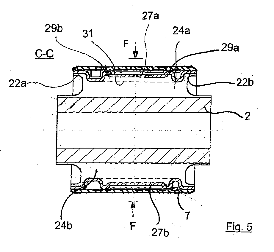
Die Erfindung betrifft eine elastische Lagerbuchse mit hydraulischer Dämpfung mit einem Innenteil (2) zur Verbindung mit einem ersten zu lagernden Bauteil und einem Außenrohr (3), mit einem Elastomerkörper (4) zwischen dem Innenteil (2) und dem Außenrohr (3), mit zwei, radial gegenüberliegenden, mit hydraulischer Flüssigkeit gefüllten und durch einen Strömungskanal (10a, 10b) verbundene Arbeitskammern (5, 6), die durch zugeordnete Aussparungen im Außenrohr (3) und im Elastomerkörper (4) sowie durch eine flüssigkeitsdicht abschließende Außenhülse (7) gebildet sind. Erfindungsgemäß ist das Außenrohr (3) als einteiliges Käfigteil ausgebildet, mit jeweils einem stirnseitig umlaufend geschlossenen Stützringteil (22a, 22b) und mit zwei radial gegenüberliegenden, die Stützringteile (22a, 22b) axial verbindenden Rohrstegteilen (23a, 23b). In den Rohrstegteilen (23a, 23b) ist jeweils ein Fenster (26a, 26b) angebracht, dem ein Druckelement (27a, 27b; 31) zugeordnet ist, welches im Fensterbereich angeordnet ist und vor der Montage der Außenhülse (7) radial weiter als der Innendurchmesser der Außenhülse (7) vorsteht, so dass beim Aufstecken der Außenhülse (7) das wenigstens eine Druckelement (27a, 27b; 31) nach radial innen unter Aufbringung einer Vorspannung im Elastomerkörper (4; 24a, 24b) verlagert wird.
Applications Claiming Priority (1)
| Application Number | Priority Date | Filing Date | Title |
|---|---|---|---|
| DE200610047445 DE102006047445A1 (en) | 2006-10-07 | 2006-10-07 | Elastic bushing with hydraulic damping |
Publications (2)
| Publication Number | Publication Date |
|---|---|
| EP1908987A2 EP1908987A2 (en) | 2008-04-09 |
| EP1908987A3 true EP1908987A3 (en) | 2010-07-07 |
Family
ID=38984234
Family Applications (1)
| Application Number | Title | Priority Date | Filing Date |
|---|---|---|---|
| EP07019119A Withdrawn EP1908987A3 (en) | 2006-10-07 | 2007-09-28 | Elastic bearing sleeve with hydraulic damping |
Country Status (2)
| Country | Link |
|---|---|
| EP (1) | EP1908987A3 (en) |
| DE (1) | DE102006047445A1 (en) |
Families Citing this family (4)
| Publication number | Priority date | Publication date | Assignee | Title |
|---|---|---|---|---|
| DE102007022410B4 (en) | 2007-05-10 | 2017-03-23 | Audi Ag | Hydraulically damping elastomer bush |
| CN108343701B (en) * | 2017-01-23 | 2020-07-14 | 株洲时代瑞唯减振装备有限公司 | Hydraulic bushing |
| DE102017106289B4 (en) * | 2017-03-23 | 2019-09-12 | Vibracoustic Gmbh | bearing bush |
| DE102020134593A1 (en) * | 2020-12-22 | 2022-06-23 | Vibracoustic Se | Hydraulic bush with support points and method for manufacturing such a bush |
Citations (4)
| Publication number | Priority date | Publication date | Assignee | Title |
|---|---|---|---|---|
| JPH0565933A (en) * | 1991-09-06 | 1993-03-19 | Bridgestone Corp | Vibration control equipment |
| WO2003025419A1 (en) * | 2001-09-19 | 2003-03-27 | Trelleborg Automotive Technical Centre Gmbh | Hydraulic damping sleeve |
| EP1467120A2 (en) * | 2003-04-08 | 2004-10-13 | HONDA MOTOR CO., Ltd. | Liquid sealed mount device |
| EP1701057A1 (en) * | 2005-03-08 | 2006-09-13 | C.F. GOMMA S.p.A. | Hydroelastic mounting, in particular for connecting a propulsion unit to a vehicle |
-
2006
- 2006-10-07 DE DE200610047445 patent/DE102006047445A1/en not_active Withdrawn
-
2007
- 2007-09-28 EP EP07019119A patent/EP1908987A3/en not_active Withdrawn
Patent Citations (4)
| Publication number | Priority date | Publication date | Assignee | Title |
|---|---|---|---|---|
| JPH0565933A (en) * | 1991-09-06 | 1993-03-19 | Bridgestone Corp | Vibration control equipment |
| WO2003025419A1 (en) * | 2001-09-19 | 2003-03-27 | Trelleborg Automotive Technical Centre Gmbh | Hydraulic damping sleeve |
| EP1467120A2 (en) * | 2003-04-08 | 2004-10-13 | HONDA MOTOR CO., Ltd. | Liquid sealed mount device |
| EP1701057A1 (en) * | 2005-03-08 | 2006-09-13 | C.F. GOMMA S.p.A. | Hydroelastic mounting, in particular for connecting a propulsion unit to a vehicle |
Also Published As
| Publication number | Publication date |
|---|---|
| EP1908987A2 (en) | 2008-04-09 |
| DE102006047445A1 (en) | 2008-04-10 |
Similar Documents
| Publication | Publication Date | Title |
|---|---|---|
| DE102019206455B4 (en) | Vibration damper with two adjustable damping valve devices | |
| EP2114801B1 (en) | Bearing arrangement for a load-bearing roller | |
| DE112015003280B4 (en) | Torque converter clutch with reduced back pressure | |
| EP1152166B2 (en) | Shock absorber with amplitude-dependent damping | |
| DE102019212908B4 (en) | Vibration damper with adjustable damping force | |
| EP1908987A3 (en) | Elastic bearing sleeve with hydraulic damping | |
| DE102014224829A1 (en) | Pressure change damper for a slip-controlled, hydraulic vehicle brake system and vehicle brake system with such a pressure change damper | |
| EP3194772B1 (en) | Piston pump | |
| DE112013005612B4 (en) | Slave cylinder of a release system for clutch or brake cylinders | |
| WO2017198854A1 (en) | Rotary seal assembly with pressure-activatable rotary seal, and rotary seal | |
| DE102009057165A1 (en) | Stop cartridge for a vibration damper | |
| DE102019007526B4 (en) | Hydraulically damping bushing bearing | |
| DE102013200370A1 (en) | Hydraulic damper for use in vehicle brake assembly piston pump, has inlet valve for preventing back-flow of hydraulic fluid flowed into chamber, and outlet throttle provided for throttling leaking out of hydraulic fluid from chamber | |
| EP2522878B1 (en) | Socket and method for manufacturing sockets | |
| US20160003386A1 (en) | Rotatable Joint | |
| WO2019211215A1 (en) | Vibration damper having adjustable damping valve | |
| EP2906850B1 (en) | Sleeve bearing | |
| DE102009001567B3 (en) | Vibration damper for use in vehicle, has piston rod-lateral operating area comprising connection opening that is shifted in direction of piston at deflection channel with respect to connection opening | |
| EP1657467A1 (en) | Air spring | |
| DE10316013B3 (en) | Pipe connecting piece with inner and outer shells for pipelines has inner shell connected at second end to support part for side surface of first sealing ring | |
| EP2031265B1 (en) | Seal assembly for a release system | |
| WO2018197106A1 (en) | Sealing and guide arrangement | |
| DE102012214713B4 (en) | Hydraulic piston / cylinder unit | |
| EP3064813A1 (en) | Back flow preventer | |
| DE10222217A1 (en) | Rubber bearing |
Legal Events
| Date | Code | Title | Description |
|---|---|---|---|
| PUAI | Public reference made under article 153(3) epc to a published international application that has entered the european phase |
Free format text: ORIGINAL CODE: 0009012 |
|
| AK | Designated contracting states |
Kind code of ref document: A2 Designated state(s): AT BE BG CH CY CZ DE DK EE ES FI FR GB GR HU IE IS IT LI LT LU LV MC MT NL PL PT RO SE SI SK TR |
|
| AX | Request for extension of the european patent |
Extension state: AL BA HR MK RS |
|
| PUAL | Search report despatched |
Free format text: ORIGINAL CODE: 0009013 |
|
| AK | Designated contracting states |
Kind code of ref document: A3 Designated state(s): AT BE BG CH CY CZ DE DK EE ES FI FR GB GR HU IE IS IT LI LT LU LV MC MT NL PL PT RO SE SI SK TR |
|
| AX | Request for extension of the european patent |
Extension state: AL BA HR MK RS |
|
| STAA | Information on the status of an ep patent application or granted ep patent |
Free format text: STATUS: THE APPLICATION HAS BEEN WITHDRAWN |
|
| 18W | Application withdrawn |
Effective date: 20110115 |