EP1908955A2 - Compact combustion engine for portable work machine - Google Patents
Compact combustion engine for portable work machine Download PDFInfo
- Publication number
- EP1908955A2 EP1908955A2 EP07019048A EP07019048A EP1908955A2 EP 1908955 A2 EP1908955 A2 EP 1908955A2 EP 07019048 A EP07019048 A EP 07019048A EP 07019048 A EP07019048 A EP 07019048A EP 1908955 A2 EP1908955 A2 EP 1908955A2
- Authority
- EP
- European Patent Office
- Prior art keywords
- shroud
- combustion engine
- work machine
- shield member
- portable work
- Prior art date
- Legal status (The legal status is an assumption and is not a legal conclusion. Google has not performed a legal analysis and makes no representation as to the accuracy of the status listed.)
- Granted
Links
Images



Classifications
-
- F—MECHANICAL ENGINEERING; LIGHTING; HEATING; WEAPONS; BLASTING
- F02—COMBUSTION ENGINES; HOT-GAS OR COMBUSTION-PRODUCT ENGINE PLANTS
- F02P—IGNITION, OTHER THAN COMPRESSION IGNITION, FOR INTERNAL-COMBUSTION ENGINES; TESTING OF IGNITION TIMING IN COMPRESSION-IGNITION ENGINES
- F02P11/00—Safety means for electric spark ignition, not otherwise provided for
-
- F—MECHANICAL ENGINEERING; LIGHTING; HEATING; WEAPONS; BLASTING
- F02—COMBUSTION ENGINES; HOT-GAS OR COMBUSTION-PRODUCT ENGINE PLANTS
- F02B—INTERNAL-COMBUSTION PISTON ENGINES; COMBUSTION ENGINES IN GENERAL
- F02B63/00—Adaptations of engines for driving pumps, hand-held tools or electric generators; Portable combinations of engines with engine-driven devices
- F02B63/02—Adaptations of engines for driving pumps, hand-held tools or electric generators; Portable combinations of engines with engine-driven devices for hand-held tools
-
- F—MECHANICAL ENGINEERING; LIGHTING; HEATING; WEAPONS; BLASTING
- F02—COMBUSTION ENGINES; HOT-GAS OR COMBUSTION-PRODUCT ENGINE PLANTS
- F02B—INTERNAL-COMBUSTION PISTON ENGINES; COMBUSTION ENGINES IN GENERAL
- F02B77/00—Component parts, details or accessories, not otherwise provided for
- F02B77/08—Safety, indicating, or supervising devices
-
- F—MECHANICAL ENGINEERING; LIGHTING; HEATING; WEAPONS; BLASTING
- F02—COMBUSTION ENGINES; HOT-GAS OR COMBUSTION-PRODUCT ENGINE PLANTS
- F02P—IGNITION, OTHER THAN COMPRESSION IGNITION, FOR INTERNAL-COMBUSTION ENGINES; TESTING OF IGNITION TIMING IN COMPRESSION-IGNITION ENGINES
- F02P15/00—Electric spark ignition having characteristics not provided for in, or of interest apart from, groups F02P1/00 - F02P13/00 and combined with layout of ignition circuits
- F02P15/001—Ignition installations adapted to specific engine types
Definitions
- the present invention relates to a compact combustion engine that is used to drive a portable work machine such as, for example, a brush cutter.
- the compact combustion engine of a kind that can be used to drive a brush cutter is generally known having a tendency to emit electromagnetic waves originating from the ignition system thereof. It has been recognized that when this type of combustion engine is mounted on the brush cutter for driving the latter, the level of electromagnetic waves generated by the engine ignition system in the brush cutter often exceeds the tolerance stipulated by CISPR (Comite International Special des Perturbations Radio/10s or International Special Committee on Radio Interference).
- the Japanese Laid-open Utility Mode Publication No. H02-122170 discloses a technique of shielding electromagnetic waves generated from the engine ignition system.
- the ignition distributor incorporates therein an electromagnetic shielding cover.
- This shielding cover includes a cover body made of an electric insulating material and having one side surface thereof provided with an electromagnetic shield member made of an conductive layer and is so operable as to shield the electromagnetic noises generated from the ignition distributor and also as to retain an electrically insulated relation with the ignition distributor.
- Japanese Laid-open Patent Publication No. 2001-304086 published October 31, 2001 , for example, discloses a technique to avoid an erroneous operation of an engine control sensor device, which may occur under the influence of external electromagnetic waves.
- this patent document makes use of an electromagnetic shielding cover prepared from an electroconductive plate material and fitted to a cylinder head cover of the combustion engine so that the electromagnetic waves propagating from the outside can be reflected by the electromagnetic shielding cover to thereby protect the engine control device.
- the electromagnetic shielding cover disclosed in the Japanese Laid-open Utility Mode Publication No. H02-122170 in a compact combustion engine for a portable work machine such as, for example, a brush cutter.
- the shielding cover disclosed therein is of a type incorporated inside the engine ignition distributor and connected electrically with the cylinder head cover through an electroconductive paint, applied to the cover body of a plastic material, so that the electromagnetic waves can be conducted to the ground through the cylinder head cover to thereby shield the electromagnetic waves. Since the compact combustion engine of this kind has no engine ignition distributor, the technique disclosed in this known patent document is incapable of being applied to the compact combustion engine.
- the shielding cover disclosed in the Japanese Laid-open Patent Publication No. 2001-304086 is so configured and so shaped as to cover the ignition coil, ignition plug and high voltage cord, where electromagnetic waves tend to occur, the resultant shielding cover will have a low moldability as a result of complication in shape thereof and will become expensive.
- either of those shielding covers discussed above is incapable of sufficiently suppressing emission of the electromagnetic waves propagating in a direction perpendicular to the elongated tube and/or the drive shaft employed in the portable work machine.
- the present invention is intended to provide a compact combustion engine for use in a portable work machine, which is simple in structure and inexpensive and which is effective to sufficiently suppress emission of electromagnetic waves to the outside of the combustion engine.
- a compact combustion engine for driving a portable work machine, which engine includes a cylinder block, an ignition coil unit and a high voltage cord for electrically connecting the ignition coil unit with an ignition plug.
- the compact combustion engine also includes a shroud for enclosing at least the cylinder block, ignition coil unit and high voltage cord and an electromagnetic shield member applied to at least a portion of the shroud which confronts the ignition coil unit and the high voltage cord.
- the electromagnetic shield member applied only to a portion of any existing shroud, which confronts the ignition coil unit and the high voltage cord, allows the compact combustion engine to be simple in structure and inexpensive, but also emission of the electromagnetic waves from the ignition coil unit and the high voltage cord, where electromagnetic waves of the highest intensity tend to occur, to the outside of the compact combustion engine can be effectively suppressed by the electromagnetic shield member.
- the electromagnetic shield member is preferably applied to an inner surface of the shroud.
- Such application is particularly advantageous in that, since the electromagnetic shield member is in no way exposed to the weather and sunlight, the electromagnetic shield member can have an increased durability. Furthermore, the electromagnetic shield member is concealed by the shroud to avoid deterioration of the appearance.
- that surface of the shroud, where the electromagnetic shield member is applied is formed with surface indentations, either or both of furrows and ridges, to enhance adherence of the electromagnetic shield member to that surface of the shroud.
- the electromagnetic shield member which may be either a spraying or a brushing of an electromagnetic shielding material in a liquid phase to deposit it on the surface of the shroud, is employed, the electromagnetic shielding material so applied can be retained on the surface of the shroud in the presence of surface indentations, without drooping down, until the applied shielding material gets dried, and also the resultant electromagnetic shield member can be firmly clung to the surface of the shroud.
- the electromagnetic shield member employed in the practice of the present invention may be preferably a resinous layer containing a resin as a principal component, which is mixed with a powder of nickel that is excellent in shielding effect.
- the electromagnetic shield member may be preferably formed on a surface of the plug cover that confronts the ignition plug and the high voltage cord. This is particularly advantageous in that emission of the electromagnetic waves to the outside of the combustion engine can be further effectively suppressed.
- a portable work machine in the form of a brush cutter 1 equipped with a compact combustion engine E according to the preferred embodiment of the present invention.
- the combustion engine E is shown as mounted on a base end of an elongated main tube 2 made of an aluminum alloy and a work tool, shown in the form of a rotary cutter blade 3, is rotatably mounted on a free end of the elongated main tube 2 remote from the combustion engine E.
- a drive shaft (not shown) for transmitting the drive of the combustion engine E to the rotary cutter blade 3 rotatably extends inside and through the elongated main tube 2 with its opposite ends drivingly coupled respectively with the combustion engine E and the rotary cutter blade 3.
- the main tube 2 has a shoulder strap 4 and a generally U-shaped handlebar 7 secured to a portion thereof a distance axially inwardly from the base end of the main tube 2.
- the number of revolutions of the rotary cutter blade 3 can be adjusted by manipulating a throttle lever 9 mounted on a portion of the handlebar 7 adjacent one of the grips 8.
- Figs. 2 and 3 illustrate a schematic perspective view of the combustion engine E and a schematic front sectional view of the same.
- the illustrated combustion engine E is a two cycle combustion engine.
- This combustion engine E includes, as best shown in Fig. 3, a cylinder block 10 having an engine cylinder 10a defined therein, and a cylinder head 10b mounted atop the cylinder block 10, or otherwise formed integrally therewith, and having an ignition plug mounting hole 10c defined therein in communication with the engine cylinder 10a for the support therein of an ignition plug 20.
- the cylinder block 10 is mounted on a crankcase 11.
- the cylinder block 10 has a fuel intake port 12 defined therein and communicated with an air cleaner 17 by way of a carburetor 14, with an insulator 13 intervening between the intake port 12 and the carburetor 14.
- the cylinder block 10 also has an exhaust port 18 defined therein and communicated with an exhaust muffler 19.
- a fuel tank 33 is secured externally to the crankcase 11 from below.
- the cylinder 10a of the cylinder block 10 accommodates a piston 15 slidably in a cylinder bore.
- the crankcase 11 rotatably supports a crankshaft 21 to which the piston 15 is connected.
- the crankshaft 21 has first or front and second or rear end portions opposite to each other and positioned outside the crankcase 11.
- This crankshaft 21 includes a cooling fan 22, capable of concurrently serving as a flywheel mounted on the first end portion thereof for rotation together, with a centrifugal clutch assembly 23 mounted thereon at a location axially outwardly of the cooling fan 22.
- the centrifugal clutch assembly 23 is operable to transmit the drive of the combustion engine E to the drive shaft of the brush cutter 1, which extends rotatably within the elongated main tube 2 shown in Fig. 1, and is, therefore, drivingly coupled in part with the crankshaft 21 and in part with the brush cutter drive shaft.
- the cooling fan 22 has an outer peripheral portion embedded with a magnet (not shown) and is covered by a fan housing 26 secured to the crankcase 11 at a location forwardly thereof, and the fan housing 26 is secured to the base end of the main tube 2 through a clutch housing 45 shown by the phantom lines in Figs. 2 and 4. It is to be noted that the centrifugal clutch assembly 23 referred to above is not illustrated in Fig. 2 for the sake of brevity.
- the second or rear end portion of the crankshaft 21, remote from the cooling fan 22, has a starter pulley 24 mounted thereon for rotation together therewith, and a recoil starter 27 is positioned axially rearwardly of the starter pulley 24 and is operatively associated therewith for driving the crankshaft 21 through the starter pulley 24 at the time the combustion engine E is started.
- a stream of cooling air C induced by and supplied from the cooling fan 22 is guided by the shroud 30, substantially enclosing an ignition coil unit 28 (as will be described later), the cylinder block 10 and the exhaust muffler 19, so as to flow towards the ignition coil unit 28 to cool the latter.
- the cooling air stream C is subsequently guided by the shroud 30 so as to flow multiple spaces, each defined between neighboring fins 10d integral with the cylinder block 10, to thereby cool the latter.
- the cooling air stream C is discharged to the outside of the combustion engine E through vent holes 30c defined in the shroud 30 so as to open generally rearwardly.
- part of the cooled air stream C flowing inside the shroud 30 is guided by a baffle plate 37 of generally L-shape in a horizontal cross section so as to flow towards the exhaust muffler 19 to cool the latter prior to being discharged to the outside particularly through different vent holes 30d defined in the shroud 30 so as to open in one direction generally opposite to the carburetor 17 and sidewise of the combustion engine E.
- This ignition coil unit 28 cooperates with the built-in ignition coil and the magnet, embedded in the cooling fan as hereinbefore described for rotation together with the cooling fan 22, to generate a high voltage required to cause the ignition plug 20 to fire.
- the ignition coil unit 28 has a high voltage cord 29 outwardly extending therefrom and terminating in electrically connected relation with the ignition plug 20.
- the shroud 30 made of a resinous material includes a main cover body 30a and a sub cover body 30b formed integrally therewith and is mounted on the combustion engine E so as to allow the main cover body 30a to substantially cover the cylinder block 10 and the sub cover body 30b to substantially cover the exhaust muffler 19. As shown and described with particular reference to Fig. 2, even both of the ignition coil unit 28 and the high voltage cord 29 are also covered by the main cover body 30a.
- the ignition plug 20 has a top end portion extending to the outside of the shroud 30 through a plug opening 30e defined in the main cover body 30a as shown in Fig. 3, that top end portion of the ignition plug 20 so exposed to the outside through the plug opening 30e is in turn covered by a separate plug cover 31.
- This separate plug cover 31 includes a plug cap 31a, electrically connected with the high voltage cord 29 and removably capped onto the top end portion of the ignition plug 20, and a cover segment 31b formed integrally with the plug cap 31 and engaged with the main cover body 30a so as to close the plug opening 30e defined in the main cover body 30a.
- the plug cover 31 of the structure described above is effective to protect the ignition plug 20 from contacting any other elements existing in the vicinity of and around the ignition plug 20.
- the air cleaner 17 is covered by a cleaner cover 32 separate from the shroud 30, but connected with the main cover body 30a of the shroud 30.
- the shroud 30 has been shown and described as made up of an integral unit of the main cover body 30a and the sub cover body 30b, the shroud may be of a structure representing a shape similar to the shape of only the main cover body 30a and the use may be made concurrently of an exhaust muffler cover that is connected with the shroud.
- Fig. 5 illustrates a bottom plan view of the shroud 30 as viewed from below, and the main cover body 30a of the shroud 30 has an inner surface provided with an electromagnetic shield member 34 effective to noticeably or substantially prevent electromagnetic waves from passing across the main cover body 30a.
- This electromagnetic shield member 34 is in the form of a layer formed by spraying, brushing, painting or coating, or otherwise applying in any way whatsoever, a shielding material in a liquid phase to the inner surface of the shroud 30, particularly that of the main cover body 30a.
- the shielding material referred to above is preferably a resinous material containing a resin, for example, a synthetic resin, as a principal component mixed with a powder of nickel and may be suitably employed in the form of, for example, a commercially available product tradenamed "FINE EM COAT (FC-173)" available from Fine Chemical Japan Co., Ltd., a corporation of Japan.
- a resinous material containing a resin for example, a synthetic resin, as a principal component mixed with a powder of nickel
- FC-173 commercially available product tradenamed "FINE EM COAT (FC-173)" available from Fine Chemical Japan Co., Ltd., a corporation of Japan.
- the ignition coil unit 28 and the high voltage cord 29 generate electromagnetic waves as the ignition coil unit 28 operates.
- the electromagnetic shielding member 34 effective to substantially avoid passage of electromagnetic waves across the shroud 30 is formed on at least a portion of the inner surface of the main cover body 30a, which confronts the ignition coil unit 28 and the high voltage cord 29 and, more specifically, that portion of the inner surface of the main cover body 30a, which confronts the ignition coil unit 28 and the high voltage cord 29 from above and opposite sides of those component parts 28 and 29.
- the electromagnetic shielding member 34 is formed even on another extra portion peripheral to that portion of the inner surface of the main cover body 30a as clearly shown in Fig. 5.
- the cooling fan 22 and/or the cylinder block 10 which is capable of absorbing electromagnetic waves, occupy their position in that area and, accordingly, the electromagnetic wave will not propagate further downwardly below the ignition coil unit 28 and the high voltage cord 29.
- the electromagnetic shielding member 34 may be formed on an outer surface of the plug cap 31a in the plug cover 31 and/or an inner surface of the cover segment 31 b formed integrally with the plug cap 31.
- the electromagnetic shielding material may be applied in a manner hereinbefore discussed to form the electromagnetic shield member 34 on at least a portion of the inner surface of the cover segment 31b, which confronts the ignition coil unit 28 and the high voltage cord 29, but in the illustrated embodiment, the electromagnetic shielding member 34 is shown as formed on the entire inner surface of the cover segment 31b.
- the electromagnetic waves emanating from the ignition coil unit 28 and the high voltage cord 29 are, after having been amplified by an antenna function of the elongated main tube 2, are likely to be radiated in a direction substantially perpendicular to the elongated main tube 2.
- the electromagnetic shield member 34 formed on the inner surface of the shroud 30 as hereinbefore described such electromagnetic waves can be effectively prevented from radiating in a direction outwardly of the combustion engine E.
- the electromagnetic shielding material eventually forming the electromagnetic shield member 34, is applied merely to that surface portion of the main cover body 30a of the existing shroud 30, which confronts the ignition coil unit 28 and the high voltage cord 29, the compact combustion engine E with electromagnetic shielding function can be assembled easily and inexpensively.
- the electromagnetic shield member 34 can work satisfactory in shielding the electromagnetic waves even though such shield member 34 is formed on either one of the inner and outer surfaces of the shroud 30, but in the illustrated embodiment, the electromagnetic shield member 34 is formed on the inner surface of the main cover body 30a of the shroud 30. Accordingly, as compared with the electromagnetic shield member 34 formed on the outer surface of the shroud 30, the electromagnetic shield member 34 is in no way exposed to the weather and sunlight and, hence, the electromagnetic shield member 34 can have a substantially increased lifetime.
- the electromagnetic shielding material eventually forming the electromagnetic shield member 34 is applied, for example, either painted or deposited, to the shroud 30 while it is in a liquid phase, it may be often observed that the electromagnetic shielding material so applied may droop downwards along the surface portion of the shroud 30 before it is completely dried. Accordingly, in the illustrated embodiment, as best shown in Fig.
- the entire inner surface portion of the main cover body 30a of the shroud 30, where the electromagnetic shield member 34 is applied is formed with a multiplicity of surface indentations, for example, furrows arranged in a grid pattern, with some of them extending in one direction and some of them extending in a direction perpendicular to such one direction, so as to leave recesses 30aa in that surface portion of the main cover body 30a as best shown in Fig. 6B.
- the pitch between the neighboring furrows or ridges that are arranged in the grid pattern, the width and the depth of each furrow or ridge may be all selected in consideration of the required adherence exhibited between the electromagnetic shield member 34 and the shroud 30.
- the recesses 30aa may be defined by furrows each having a small width as shown in Fig. 7.
- the recesses 30aa may be replaced with a multiplicity of round dimples defined in and distributed uniformly on the inner surface portion of the shroud 30, where the electromagnetic shield member 34 is desired to be interlocked with the shroud 30, as shown in Fig. 8A and 8B.
- a grid pattern of ridges 30ab may be formed on that inner surface portion of the main cover body 30a, where the electromagnetic shield member 34 is desired to be interlocked with the shroud 30, as shown in Fig.9.
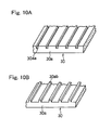
- the recesses 30aa or the ridges 30ab may be arranged so as to be lined up in rows on one-dimensional plane while extending parallel to each other as shown in Figs. 10A or Fig. 10B, respectively.
- an adhesive sheet 38 having a surface area sufficient to encompass the electromagnetic shield member 34 may be placed over the electromagnetic shield member 34 with its peripheral portion bonded to the inner surface of the main cover body 30a.
- a retaining plate 39 made of a synthetic resin and having a surface area sufficient to encompass the electromagnetic shield member 34 may be placed over and in contact with the electromagnetic shield member 34 with its peripheral portion connected to the inner surface of the main cover body 30a by means of a plurality of set screws 40.
- the electromagnetic shield member formed by a fabric-like sheet impregnated with the electromagnetic shielding material and having a bonding material deposited thereon may be bonded to that inner surface portion of the main cover body 30a of the shroud 30.
- the present invention although reference has been made to the portable work machine employed in the form of the brush cutter may be equally applied to any other portable work machine such as, for example, a hedge trimmer or a tea-leaf harvesting machine and specifically to any other portable work machine of a structure including an elongated operating member tending to work as an antenna for the electromagnetic waves.
Landscapes
- Engineering & Computer Science (AREA)
- Chemical & Material Sciences (AREA)
- Combustion & Propulsion (AREA)
- Mechanical Engineering (AREA)
- General Engineering & Computer Science (AREA)
- Ignition Installations For Internal Combustion Engines (AREA)
Abstract
Description
- The present invention relates to a compact combustion engine that is used to drive a portable work machine such as, for example, a brush cutter.
- The compact combustion engine of a kind that can be used to drive a brush cutter is generally known having a tendency to emit electromagnetic waves originating from the ignition system thereof. It has been recognized that when this type of combustion engine is mounted on the brush cutter for driving the latter, the level of electromagnetic waves generated by the engine ignition system in the brush cutter often exceeds the tolerance stipulated by CISPR (Comite International Special des Perturbations Radioelectriques or International Special Committee on Radio Interference). The inventors investigated the cause and found that, since the drive shaft of the brush cutter is enclosed by and extends within a elongated tube or the like made of an aluminum alloy, the elongated tube or the like enclosing the drive shaft acts as an antenna to amplify the electromagnetic waves from the engine ignition system by the effect of an electromagnetic induction within the elongated tube, with the high intensity electromagnetic waves generated consequently in a direction perpendicular to the elongated tube.
- While it has hitherto been a general practice to insert a resistor of, for example, about 10 KΩ in an ignition plug, a high voltage cord or a plug cap to lower the electric current to thereby suppress the generation of the electromagnetic waves, the use of the resistor in this way does not work satisfactorily in suppressing the electromagnetic waves particularly where the latter are amplified by the elongated tube. Also, in a portable work machine mounted with a compact combustion engine of a type having a CDI (Capacitor Discharged Ignition) system, considerable electromagnetic noises tend to be generated with abrupt increase of the electric current flowing in the CDI system and, accordingly, the effect of suppressing the electromagnetic waves is still far from being satisfactory.
- On the other hand, the
Japanese Laid-open Utility Mode Publication No. H02-122170, published October 5, 1990 - Also, the
Japanese Laid-open Patent Publication No. 2001-304086, published October 31, 2001 - In view of the foregoing, it may be contemplated to use the electromagnetic shielding cover disclosed in the
Japanese Laid-open Utility Mode Publication No. H02-122170 - Also, if the shielding cover disclosed in the
Japanese Laid-open Patent Publication No. 2001-304086 - In any event, either of those shielding covers discussed above is incapable of sufficiently suppressing emission of the electromagnetic waves propagating in a direction perpendicular to the elongated tube and/or the drive shaft employed in the portable work machine.
- In view of the foregoing, the present invention is intended to provide a compact combustion engine for use in a portable work machine, which is simple in structure and inexpensive and which is effective to sufficiently suppress emission of electromagnetic waves to the outside of the combustion engine.
- In order to accomplish the foregoing object of the present invention, there is provided a compact combustion engine for driving a portable work machine, which engine includes a cylinder block, an ignition coil unit and a high voltage cord for electrically connecting the ignition coil unit with an ignition plug. The compact combustion engine also includes a shroud for enclosing at least the cylinder block, ignition coil unit and high voltage cord and an electromagnetic shield member applied to at least a portion of the shroud which confronts the ignition coil unit and the high voltage cord.
- According to the present invention, not only can the use of the electromagnetic shield member applied only to a portion of any existing shroud, which confronts the ignition coil unit and the high voltage cord, allows the compact combustion engine to be simple in structure and inexpensive, but also emission of the electromagnetic waves from the ignition coil unit and the high voltage cord, where electromagnetic waves of the highest intensity tend to occur, to the outside of the compact combustion engine can be effectively suppressed by the electromagnetic shield member.
- In a preferred embodiment of the present invention, the electromagnetic shield member is preferably applied to an inner surface of the shroud. Such application is particularly advantageous in that, since the electromagnetic shield member is in no way exposed to the weather and sunlight, the electromagnetic shield member can have an increased durability. Furthermore, the electromagnetic shield member is concealed by the shroud to avoid deterioration of the appearance.
- In another preferred embodiment of the present invention, that surface of the shroud, where the electromagnetic shield member is applied, is formed with surface indentations, either or both of furrows and ridges, to enhance adherence of the electromagnetic shield member to that surface of the shroud. Even if the simplest method of forming the electromagnetic shield member, which may be either a spraying or a brushing of an electromagnetic shielding material in a liquid phase to deposit it on the surface of the shroud, is employed, the electromagnetic shielding material so applied can be retained on the surface of the shroud in the presence of surface indentations, without drooping down, until the applied shielding material gets dried, and also the resultant electromagnetic shield member can be firmly clung to the surface of the shroud.
- The electromagnetic shield member employed in the practice of the present invention may be preferably a resinous layer containing a resin as a principal component, which is mixed with a powder of nickel that is excellent in shielding effect.
- Also, where the compact combustion engine includes a plug cover for covering a top end portion of the ignition plug that protrude outwardly from the shroud, the electromagnetic shield member may be preferably formed on a surface of the plug cover that confronts the ignition plug and the high voltage cord. This is particularly advantageous in that emission of the electromagnetic waves to the outside of the combustion engine can be further effectively suppressed.
- In any event, the present invention will become more clearly understood from the following description of preferred embodiments thereof, when taken in conjunction with the accompanying drawings. However, the embodiments and the drawings are given only for the purpose of illustration and explanation, and are not to be taken as limiting the scope of the present invention in any way whatsoever, which scope is to be determined by the appended claims. In the accompanying drawings, like reference numerals are used to denote like parts throughout the several views, and:
- Fig. 1 is a perspective view of a portable work machine equipped with a compact combustion engine according to a preferred embodiment of the present invention;
- Fig. 2 is a perspective view of the compact combustion engine shown in Fig. 1;
- Fig. 3 is a front sectional view of the compact combustion engine;
- Fig. 4 is a cross-sectional view taken along the line IV-IV in Fig. 3;
- Fig. 5 is a bottom plan view of a shroud employed in the compact combustion engine;
- Fig. 6A is a fragmentary bottom plan view showing a portion of the shroud;
- Fig. 6B is a cross-sectional view taken along the line VI-VI in Fig. 6A, showing an electromagnetic shielding layer formed on the shroud;
- Fig. 7 is a fragmentary sectional view of that portion of a modified form of the shroud;
- Fig. 8A is a fragmentary bottom plan view showing that portion of another modified form of the shroud;
- Fig. 8B is a cross-sectional view taken along the line VIII-VIII in Fig. 8A, showing an electromagnetic shielding layer formed on the shroud;
- Fig. 9 is a fragmentary sectional plan view showing that portion of a further modified form of the shroud;
- Fig. 10A is a fragmentary perspective view showing that portion of a still modified form of the shroud;
- Fig. 10B is a fragmentary perspective view showing that portion of a yet modified form of the shroud;
- Fig. 11 is a fragmentary sectional view showing that portion of a still further modified form of the shroud; and
- Fig. 12 is a fragmentary sectional view showing that portion of a yet further modified form of the shroud.
- Hereinafter, a preferred embodiment of the present invention will be described with particular reference to the accompanying drawings.
- Referring to Fig. 1, there is shown a portable work machine in the form of a brush cutter 1 equipped with a compact combustion engine E according to the preferred embodiment of the present invention. The combustion engine E is shown as mounted on a base end of an elongated main tube 2 made of an aluminum alloy and a work tool, shown in the form of a
rotary cutter blade 3, is rotatably mounted on a free end of the elongated main tube 2 remote from the combustion engine E. A drive shaft (not shown) for transmitting the drive of the combustion engine E to therotary cutter blade 3 rotatably extends inside and through the elongated main tube 2 with its opposite ends drivingly coupled respectively with the combustion engine E and therotary cutter blade 3. - The main tube 2 has a shoulder strap 4 and a generally U-shaped handlebar 7 secured to a portion thereof a distance axially inwardly from the base end of the main tube 2. Carrying the brush cutter 1 on his or her shoulder with the shoulder strap 4 turned around the shoulder and with his or her hands holding respective grips 8 at opposite ends of the handlebar 7, the attendant worker can maneuver the brush cutter 1 to cause the
rotary cutter blade 3, then driven by the combustion engine E, to cut the brush. The number of revolutions of therotary cutter blade 3 can be adjusted by manipulating a throttle lever 9 mounted on a portion of the handlebar 7 adjacent one of the grips 8. - Figs. 2 and 3 illustrate a schematic perspective view of the combustion engine E and a schematic front sectional view of the same. The illustrated combustion engine E is a two cycle combustion engine. This combustion engine E includes, as best shown in Fig. 3, a
cylinder block 10 having anengine cylinder 10a defined therein, and acylinder head 10b mounted atop thecylinder block 10, or otherwise formed integrally therewith, and having an ignitionplug mounting hole 10c defined therein in communication with theengine cylinder 10a for the support therein of anignition plug 20. - The
cylinder block 10 is mounted on acrankcase 11. Thecylinder block 10 has afuel intake port 12 defined therein and communicated with anair cleaner 17 by way of acarburetor 14, with aninsulator 13 intervening between theintake port 12 and thecarburetor 14. Thecylinder block 10 also has anexhaust port 18 defined therein and communicated with anexhaust muffler 19. Afuel tank 33 is secured externally to thecrankcase 11 from below. - As best shown in Fig. 4 showing a cross-sectional view of the combustion engine E taken along the line IV-IV in Fig. 3, the
cylinder 10a of thecylinder block 10 accommodates apiston 15 slidably in a cylinder bore. Thecrankcase 11 rotatably supports acrankshaft 21 to which thepiston 15 is connected. Thecrankshaft 21 has first or front and second or rear end portions opposite to each other and positioned outside thecrankcase 11. Thiscrankshaft 21 includes a coolingfan 22, capable of concurrently serving as a flywheel mounted on the first end portion thereof for rotation together, with a centrifugalclutch assembly 23 mounted thereon at a location axially outwardly of the coolingfan 22. The centrifugalclutch assembly 23 is operable to transmit the drive of the combustion engine E to the drive shaft of the brush cutter 1, which extends rotatably within the elongated main tube 2 shown in Fig. 1, and is, therefore, drivingly coupled in part with thecrankshaft 21 and in part with the brush cutter drive shaft. - The cooling
fan 22 has an outer peripheral portion embedded with a magnet (not shown) and is covered by afan housing 26 secured to thecrankcase 11 at a location forwardly thereof, and thefan housing 26 is secured to the base end of the main tube 2 through aclutch housing 45 shown by the phantom lines in Figs. 2 and 4. It is to be noted that the centrifugalclutch assembly 23 referred to above is not illustrated in Fig. 2 for the sake of brevity. - As best shown in Fig. 4, the second or rear end portion of the
crankshaft 21, remote from the coolingfan 22, has astarter pulley 24 mounted thereon for rotation together therewith, and a recoil starter 27 is positioned axially rearwardly of thestarter pulley 24 and is operatively associated therewith for driving thecrankshaft 21 through thestarter pulley 24 at the time the combustion engine E is started. - In the combustion engine E of the structure described hereinabove, a stream of cooling air C induced by and supplied from the cooling
fan 22 is guided by theshroud 30, substantially enclosing an ignition coil unit 28 (as will be described later), thecylinder block 10 and theexhaust muffler 19, so as to flow towards theignition coil unit 28 to cool the latter. The cooling air stream C is subsequently guided by theshroud 30 so as to flow multiple spaces, each defined between neighboringfins 10d integral with thecylinder block 10, to thereby cool the latter. Thereafter, the cooling air stream C is discharged to the outside of the combustion engine E throughvent holes 30c defined in theshroud 30 so as to open generally rearwardly. However, in the illustrated embodiment, part of the cooled air stream C flowing inside theshroud 30 is guided by abaffle plate 37 of generally L-shape in a horizontal cross section so as to flow towards theexhaust muffler 19 to cool the latter prior to being discharged to the outside particularly throughdifferent vent holes 30d defined in theshroud 30 so as to open in one direction generally opposite to thecarburetor 17 and sidewise of the combustion engine E. - Referring now to Fig. 4, the
ignition coil unit 28 of a CDI system having a high voltage generating circuit (not shown) built therein and including, for example, an ignition coil (also not shown) is disposed inside theshroud 30 and forwardly of thecylinder block 10. Thisignition coil unit 28 cooperates with the built-in ignition coil and the magnet, embedded in the cooling fan as hereinbefore described for rotation together with the coolingfan 22, to generate a high voltage required to cause theignition plug 20 to fire. As best shown in Fig. 2, theignition coil unit 28 has ahigh voltage cord 29 outwardly extending therefrom and terminating in electrically connected relation with theignition plug 20. - As best shown in Fig. 3, the
shroud 30 made of a resinous material includes amain cover body 30a and asub cover body 30b formed integrally therewith and is mounted on the combustion engine E so as to allow themain cover body 30a to substantially cover thecylinder block 10 and thesub cover body 30b to substantially cover theexhaust muffler 19. As shown and described with particular reference to Fig. 2, even both of theignition coil unit 28 and thehigh voltage cord 29 are also covered by themain cover body 30a. - Although the
ignition plug 20 has a top end portion extending to the outside of theshroud 30 through aplug opening 30e defined in themain cover body 30a as shown in Fig. 3, that top end portion of theignition plug 20 so exposed to the outside through theplug opening 30e is in turn covered by aseparate plug cover 31. Thisseparate plug cover 31 includes aplug cap 31a, electrically connected with thehigh voltage cord 29 and removably capped onto the top end portion of theignition plug 20, and acover segment 31b formed integrally with theplug cap 31 and engaged with themain cover body 30a so as to close theplug opening 30e defined in themain cover body 30a. The plug cover 31 of the structure described above is effective to protect the ignition plug 20 from contacting any other elements existing in the vicinity of and around theignition plug 20. - On the other hand, the
air cleaner 17 is covered by acleaner cover 32 separate from theshroud 30, but connected with themain cover body 30a of theshroud 30. It is to be noted that although in the illustrated embodiment, theshroud 30 has been shown and described as made up of an integral unit of themain cover body 30a and thesub cover body 30b, the shroud may be of a structure representing a shape similar to the shape of only themain cover body 30a and the use may be made concurrently of an exhaust muffler cover that is connected with the shroud. - Fig. 5 illustrates a bottom plan view of the
shroud 30 as viewed from below, and themain cover body 30a of theshroud 30 has an inner surface provided with anelectromagnetic shield member 34 effective to noticeably or substantially prevent electromagnetic waves from passing across themain cover body 30a. Thiselectromagnetic shield member 34 is in the form of a layer formed by spraying, brushing, painting or coating, or otherwise applying in any way whatsoever, a shielding material in a liquid phase to the inner surface of theshroud 30, particularly that of themain cover body 30a. The shielding material referred to above is preferably a resinous material containing a resin, for example, a synthetic resin, as a principal component mixed with a powder of nickel and may be suitably employed in the form of, for example, a commercially available product tradenamed "FINE EM COAT (FC-173)" available from Fine Chemical Japan Co., Ltd., a corporation of Japan. - The
ignition coil unit 28 and thehigh voltage cord 29 generate electromagnetic waves as theignition coil unit 28 operates. As clearly shown in Figs. 3 and 4, theelectromagnetic shielding member 34 effective to substantially avoid passage of electromagnetic waves across theshroud 30 is formed on at least a portion of the inner surface of themain cover body 30a, which confronts theignition coil unit 28 and thehigh voltage cord 29 and, more specifically, that portion of the inner surface of themain cover body 30a, which confronts theignition coil unit 28 and thehigh voltage cord 29 from above and opposite sides of thosecomponent parts main cover body 30a confronting theignition coil unit 28 and thehigh voltage cord 29, theelectromagnetic shielding member 34 is formed even on another extra portion peripheral to that portion of the inner surface of themain cover body 30a as clearly shown in Fig. 5. With respect to an area below theignition coil unit 28 and thehigh voltage cord 29, the coolingfan 22 and/or thecylinder block 10, which is capable of absorbing electromagnetic waves, occupy their position in that area and, accordingly, the electromagnetic wave will not propagate further downwardly below theignition coil unit 28 and thehigh voltage cord 29. - It is to be noted that the
electromagnetic shielding member 34 may be formed on an outer surface of theplug cap 31a in theplug cover 31 and/or an inner surface of thecover segment 31 b formed integrally with theplug cap 31. In particular, where theelectromagnetic shielding member 34 is desired to be formed on thecover segment 31b, the electromagnetic shielding material may be applied in a manner hereinbefore discussed to form theelectromagnetic shield member 34 on at least a portion of the inner surface of thecover segment 31b, which confronts theignition coil unit 28 and thehigh voltage cord 29, but in the illustrated embodiment, theelectromagnetic shielding member 34 is shown as formed on the entire inner surface of thecover segment 31b. - In the portable work machine of the structure hereinbefore fully described, the electromagnetic waves emanating from the
ignition coil unit 28 and thehigh voltage cord 29 are, after having been amplified by an antenna function of the elongated main tube 2, are likely to be radiated in a direction substantially perpendicular to the elongated main tube 2. However, in the presence of and due to theelectromagnetic shield member 34 formed on the inner surface of theshroud 30 as hereinbefore described, such electromagnetic waves can be effectively prevented from radiating in a direction outwardly of the combustion engine E. Also, since the electromagnetic shielding material, eventually forming theelectromagnetic shield member 34, is applied merely to that surface portion of themain cover body 30a of the existingshroud 30, which confronts theignition coil unit 28 and thehigh voltage cord 29, the compact combustion engine E with electromagnetic shielding function can be assembled easily and inexpensively. - In addition, the
electromagnetic shield member 34 can work satisfactory in shielding the electromagnetic waves even thoughsuch shield member 34 is formed on either one of the inner and outer surfaces of theshroud 30, but in the illustrated embodiment, theelectromagnetic shield member 34 is formed on the inner surface of themain cover body 30a of theshroud 30. Accordingly, as compared with theelectromagnetic shield member 34 formed on the outer surface of theshroud 30, theelectromagnetic shield member 34 is in no way exposed to the weather and sunlight and, hence, theelectromagnetic shield member 34 can have a substantially increased lifetime. - In the meantime, considering that the electromagnetic shielding material eventually forming the
electromagnetic shield member 34 is applied, for example, either painted or deposited, to theshroud 30 while it is in a liquid phase, it may be often observed that the electromagnetic shielding material so applied may droop downwards along the surface portion of theshroud 30 before it is completely dried. Accordingly, in the illustrated embodiment, as best shown in Fig. 6A, the entire inner surface portion of themain cover body 30a of theshroud 30, where theelectromagnetic shield member 34 is applied, is formed with a multiplicity of surface indentations, for example, furrows arranged in a grid pattern, with some of them extending in one direction and some of them extending in a direction perpendicular to such one direction, so as to leave recesses 30aa in that surface portion of themain cover body 30a as best shown in Fig. 6B. - Accordingly, it is clear that when the electromagnetic shielding material is applied, a part of the electromagnetic shielding material penetrates into the recesses 30aa and, therefore, when the electromagnetic shielding material subsequently dries completely, the resultant
electromagnetic shield member 34 can be firmly retained on that surface portion of themain cover body 30a, exhibiting an increased adherence thereto while some of them are embedded within the recesses 30aa. Hence, drooping down of theelectromagnetic shielding member 34 after the application thereof to the surface portion of themain cover body 30a can be substantially avoided. - The pitch between the neighboring furrows or ridges that are arranged in the grid pattern, the width and the depth of each furrow or ridge may be all selected in consideration of the required adherence exhibited between the
electromagnetic shield member 34 and theshroud 30. By way of example, the recesses 30aa may be defined by furrows each having a small width as shown in Fig. 7. Also, as means for increasing the adherence of theelectromagnetic shield member 34 to theshroud 30 to enhance a firm retention of theshroud 30, the recesses 30aa may be replaced with a multiplicity of round dimples defined in and distributed uniformly on the inner surface portion of theshroud 30, where theelectromagnetic shield member 34 is desired to be interlocked with theshroud 30, as shown in Fig. 8A and 8B. Alternatively, in place of the recesses 30aa, a grid pattern of ridges 30ab may be formed on that inner surface portion of themain cover body 30a, where theelectromagnetic shield member 34 is desired to be interlocked with theshroud 30, as shown in Fig.9. - It is to be noted that in any one of the modifications shown in and described with reference to Figs. 6A to 9, the recesses 30aa or the ridges 30ab may be arranged so as to be lined up in rows on one-dimensional plane while extending parallel to each other as shown in Figs. 10A or Fig. 10B, respectively.
- Furthermore, as shown in Fig. 11, after the
electromagnetic shield member 34 has been formed by painting or brushing on the inner surface portion of themain cover body 30a of theshroud 30, anadhesive sheet 38 having a surface area sufficient to encompass theelectromagnetic shield member 34 may be placed over theelectromagnetic shield member 34 with its peripheral portion bonded to the inner surface of themain cover body 30a. - In a different modification shown in Fig. 12, after the
electromagnetic shield member 34 has been formed by painting or brushing on the inner surface portion of themain cover body 30a of theshroud 30, a retainingplate 39 made of a synthetic resin and having a surface area sufficient to encompass theelectromagnetic shield member 34 may be placed over and in contact with theelectromagnetic shield member 34 with its peripheral portion connected to the inner surface of themain cover body 30a by means of a plurality of set screws 40. - In a yet different modification although not shown, the electromagnetic shield member formed by a fabric-like sheet impregnated with the electromagnetic shielding material and having a bonding material deposited thereon may be bonded to that inner surface portion of the
main cover body 30a of theshroud 30. - Although the present invention has been fully described in connection with the preferred embodiments thereof with reference to the accompanying drawings which are used only for the purpose of illustration, those skilled in the art will readily conceive numerous changes and modifications within the framework of obviousness upon the reading of the specification herein presented of the present invention. By way of example, the present invention although reference has been made to the portable work machine employed in the form of the brush cutter may be equally applied to any other portable work machine such as, for example, a hedge trimmer or a tea-leaf harvesting machine and specifically to any other portable work machine of a structure including an elongated operating member tending to work as an antenna for the electromagnetic waves.
- Accordingly, such changes and modifications are, unless they depart from the scope of the present invention as delivered from the claims annexed hereto, to be construed as included therein.
Claims (9)
- A compact combustion engine for driving a portable work machine, which engine comprises:a cylinder block;an ignition coil unit;an ignition plug;a high voltage cord for electrically connecting the ignition coil unit with the ignition plug;a shroud for enclosing at least the cylinder block, ignition coil unit and high voltage cord; andan electromagnetic shield member applied to at least a portion of the shroud which confronts the ignition coil unit and the high voltage cord.
- The compact combustion engine for driving the portable work machine as claimed in Claim 1, wherein the electromagnetic shield member is applied to an inner surface of the shroud.
- The compact combustion engine for driving the portable work machine as claimed in Claim 1 or 2, wherein that surface of the shroud, where the electromagnetic shield member is applied, is formed with surface indentations to enhance adherence of the electromagnetic shield member to that surface of the shroud and wherein the surface indentations are either or both of furrows and ridges.
- The compact combustion engine for driving the portable work machine as claimed in any one of Claims 1 to 3, wherein the electromagnetic shield member is a resinous layer containing a resin as a principal component, which is mixed with a powder of nickel that is excellent in shielding effect.
- The compact combustion engine for driving the portable work machine as claimed in Claim 3 or 4, wherein the surface indentations comprise a multiplicity of ridges arranged in a grid pattern with some of them extending in one direction and some of them extending in a direction perpendicular to such one direction.
- The compact combustion engine for driving the portable work machine as claimed in Claim 3 or 4, wherein the surface indentations comprise a multiplicity of furrows arranged in a grid pattern with some of them extending in one direction and some of them extending in a direction perpendicular to such one direction.
- The compact combustion engine for driving the portable work machine as claimed in any one of Claims 3 to 6, wherein the surface indentations comprises straight furrows or ridges laid in one-dimensional arrangement while extending parallel to each other.
- The compact engine for driving the portable work machine as claimed in any one of Claims 2 to 7, wherein the electromagnetic shielding material is bonded to the inner surface of the shroud by means of an adhesive tape covering such inner surface.
- The compact combustion engine for driving the portable work machine as claimed in any one of Claims 1 to 4, further comprising a plug cover for covering a top end portion of the ignition plug that protrude outwardly from the shroud and wherein the electromagnetic shield member is formed on a surface of the plug cover that confronts the ignition plug and the high voltage cord.
Applications Claiming Priority (1)
| Application Number | Priority Date | Filing Date | Title |
|---|---|---|---|
| JP2006271155A JP2008088906A (en) | 2006-10-02 | 2006-10-02 | Small engine for portable work machines |
Publications (3)
| Publication Number | Publication Date |
|---|---|
| EP1908955A2 true EP1908955A2 (en) | 2008-04-09 |
| EP1908955A3 EP1908955A3 (en) | 2014-12-03 |
| EP1908955B1 EP1908955B1 (en) | 2017-12-06 |
Family
ID=38827445
Family Applications (1)
| Application Number | Title | Priority Date | Filing Date |
|---|---|---|---|
| EP07019048.3A Ceased EP1908955B1 (en) | 2006-10-02 | 2007-09-27 | Compact combustion engine for portable work machine |
Country Status (2)
| Country | Link |
|---|---|
| EP (1) | EP1908955B1 (en) |
| JP (1) | JP2008088906A (en) |
Family Cites Families (4)
| Publication number | Priority date | Publication date | Assignee | Title |
|---|---|---|---|---|
| FR851574A (en) * | 1938-03-16 | 1940-01-11 | Protection device for t stations. s. f. fitted in particular on board airplanes or automobiles against interference caused by ignition | |
| JP2647589B2 (en) * | 1992-01-27 | 1997-08-27 | 矢崎総業株式会社 | Composite sheet for electromagnetic wave shielding |
| DE19812880A1 (en) * | 1998-03-24 | 1999-09-30 | Bayer Ag | Shaped part and flexible film with protected conductor track and process for its production |
| JP3713184B2 (en) * | 2000-04-28 | 2005-11-02 | ダイハツ工業株式会社 | Electromagnetic shield cover |
-
2006
- 2006-10-02 JP JP2006271155A patent/JP2008088906A/en active Pending
-
2007
- 2007-09-27 EP EP07019048.3A patent/EP1908955B1/en not_active Ceased
Also Published As
| Publication number | Publication date |
|---|---|
| EP1908955B1 (en) | 2017-12-06 |
| JP2008088906A (en) | 2008-04-17 |
| EP1908955A3 (en) | 2014-12-03 |
Similar Documents
| Publication | Publication Date | Title |
|---|---|---|
| US6031306A (en) | Electric motor incorporating its own electronic control | |
| EP1908955B1 (en) | Compact combustion engine for portable work machine | |
| JP5019263B2 (en) | Working machine | |
| US8881692B2 (en) | Cooling system in air-cooled combustion engine | |
| WO2000026052A3 (en) | Mounting apparatus for an engine and transmission | |
| JP4914812B2 (en) | Radio wave shield device for engine | |
| JP4695031B2 (en) | Engine blower | |
| JP3424027B2 (en) | Foreign matter suction prevention member for air-cooled internal combustion engine | |
| JP3648474B2 (en) | Engine muffler cooling structure | |
| JP3726065B2 (en) | Engine cooling structure | |
| US11022085B2 (en) | Engine operation detection system | |
| JPS6114623Y2 (en) | ||
| JP3755310B2 (en) | 4-cycle engine generator | |
| JP2007278173A (en) | Engine stop device for portable work machine | |
| JPS6019948A (en) | Construction for fitting igniter in internal-combustion engine | |
| JP3329219B2 (en) | Outboard motor electrical component installation structure | |
| JPS6320822Y2 (en) | ||
| JP2004197594A (en) | Small engine | |
| JP3401573B2 (en) | Wiring structure of portable work machine | |
| JP2002054452A (en) | General-purpose engine fan cover structure | |
| JP2005090377A (en) | Air-cooled engine | |
| JP3062159U (en) | Electromagnetic wave shield cover | |
| JPH05106433A (en) | Electric component cooling structure for outboard motors | |
| JP5567105B2 (en) | Outboard motor | |
| JPS591112Y2 (en) | Air-cooled engine fan cover |
Legal Events
| Date | Code | Title | Description |
|---|---|---|---|
| PUAI | Public reference made under article 153(3) epc to a published international application that has entered the european phase |
Free format text: ORIGINAL CODE: 0009012 |
|
| 17P | Request for examination filed |
Effective date: 20070927 |
|
| AK | Designated contracting states |
Kind code of ref document: A2 Designated state(s): AT BE BG CH CY CZ DE DK EE ES FI FR GB GR HU IE IS IT LI LT LU LV MC MT NL PL PT RO SE SI SK TR |
|
| AX | Request for extension of the european patent |
Extension state: AL BA HR MK RS |
|
| PUAL | Search report despatched |
Free format text: ORIGINAL CODE: 0009013 |
|
| AK | Designated contracting states |
Kind code of ref document: A3 Designated state(s): AT BE BG CH CY CZ DE DK EE ES FI FR GB GR HU IE IS IT LI LT LU LV MC MT NL PL PT RO SE SI SK TR |
|
| AX | Request for extension of the european patent |
Extension state: AL BA HR MK RS |
|
| RIC1 | Information provided on ipc code assigned before grant |
Ipc: F02P 11/00 20060101AFI20141029BHEP Ipc: F02P 15/00 20060101ALI20141029BHEP Ipc: F02B 77/08 20060101ALI20141029BHEP Ipc: F02B 63/02 20060101ALI20141029BHEP |
|
| AKX | Designation fees paid |
Designated state(s): DE FR IT |
|
| AXX | Extension fees paid |
Extension state: RS Extension state: AL Extension state: HR Extension state: MK Extension state: BA |
|
| GRAP | Despatch of communication of intention to grant a patent |
Free format text: ORIGINAL CODE: EPIDOSNIGR1 |
|
| INTG | Intention to grant announced |
Effective date: 20170905 |
|
| GRAS | Grant fee paid |
Free format text: ORIGINAL CODE: EPIDOSNIGR3 |
|
| GRAA | (expected) grant |
Free format text: ORIGINAL CODE: 0009210 |
|
| AK | Designated contracting states |
Kind code of ref document: B1 Designated state(s): DE FR IT |
|
| REG | Reference to a national code |
Ref country code: DE Ref legal event code: R096 Ref document number: 602007053266 Country of ref document: DE |
|
| REG | Reference to a national code |
Ref country code: FR Ref legal event code: PLFP Year of fee payment: 12 |
|
| REG | Reference to a national code |
Ref country code: DE Ref legal event code: R097 Ref document number: 602007053266 Country of ref document: DE |
|
| PLBE | No opposition filed within time limit |
Free format text: ORIGINAL CODE: 0009261 |
|
| STAA | Information on the status of an ep patent application or granted ep patent |
Free format text: STATUS: NO OPPOSITION FILED WITHIN TIME LIMIT |
|
| PGFP | Annual fee paid to national office [announced via postgrant information from national office to epo] |
Ref country code: DE Payment date: 20180813 Year of fee payment: 12 Ref country code: IT Payment date: 20180817 Year of fee payment: 12 Ref country code: FR Payment date: 20180814 Year of fee payment: 12 |
|
| 26N | No opposition filed |
Effective date: 20180907 |
|
| REG | Reference to a national code |
Ref country code: DE Ref legal event code: R119 Ref document number: 602007053266 Country of ref document: DE |
|
| PG25 | Lapsed in a contracting state [announced via postgrant information from national office to epo] |
Ref country code: DE Free format text: LAPSE BECAUSE OF NON-PAYMENT OF DUE FEES Effective date: 20200401 |
|
| PG25 | Lapsed in a contracting state [announced via postgrant information from national office to epo] |
Ref country code: IT Free format text: LAPSE BECAUSE OF NON-PAYMENT OF DUE FEES Effective date: 20190927 |
|
| PG25 | Lapsed in a contracting state [announced via postgrant information from national office to epo] |
Ref country code: FR Free format text: LAPSE BECAUSE OF NON-PAYMENT OF DUE FEES Effective date: 20190930 |