EP1908936A1 - Elément de conduite flexible - Google Patents
Elément de conduite flexible Download PDFInfo
- Publication number
- EP1908936A1 EP1908936A1 EP06020733A EP06020733A EP1908936A1 EP 1908936 A1 EP1908936 A1 EP 1908936A1 EP 06020733 A EP06020733 A EP 06020733A EP 06020733 A EP06020733 A EP 06020733A EP 1908936 A1 EP1908936 A1 EP 1908936A1
- Authority
- EP
- European Patent Office
- Prior art keywords
- flexible
- conduit element
- element according
- flexible conduit
- bellows
- Prior art date
- Legal status (The legal status is an assumption and is not a legal conclusion. Google has not performed a legal analysis and makes no representation as to the accuracy of the status listed.)
- Granted
Links
Images

Classifications
-
- F—MECHANICAL ENGINEERING; LIGHTING; HEATING; WEAPONS; BLASTING
- F16—ENGINEERING ELEMENTS AND UNITS; GENERAL MEASURES FOR PRODUCING AND MAINTAINING EFFECTIVE FUNCTIONING OF MACHINES OR INSTALLATIONS; THERMAL INSULATION IN GENERAL
- F16L—PIPES; JOINTS OR FITTINGS FOR PIPES; SUPPORTS FOR PIPES, CABLES OR PROTECTIVE TUBING; MEANS FOR THERMAL INSULATION IN GENERAL
- F16L27/00—Adjustable joints, Joints allowing movement
- F16L27/10—Adjustable joints, Joints allowing movement comprising a flexible connection only, e.g. for damping vibrations
- F16L27/107—Adjustable joints, Joints allowing movement comprising a flexible connection only, e.g. for damping vibrations the ends of the pipe being interconnected by a flexible sleeve
- F16L27/11—Adjustable joints, Joints allowing movement comprising a flexible connection only, e.g. for damping vibrations the ends of the pipe being interconnected by a flexible sleeve the sleeve having the form of a bellows with multiple corrugations
- F16L27/111—Adjustable joints, Joints allowing movement comprising a flexible connection only, e.g. for damping vibrations the ends of the pipe being interconnected by a flexible sleeve the sleeve having the form of a bellows with multiple corrugations the bellows being reinforced
-
- F—MECHANICAL ENGINEERING; LIGHTING; HEATING; WEAPONS; BLASTING
- F01—MACHINES OR ENGINES IN GENERAL; ENGINE PLANTS IN GENERAL; STEAM ENGINES
- F01N—GAS-FLOW SILENCERS OR EXHAUST APPARATUS FOR MACHINES OR ENGINES IN GENERAL; GAS-FLOW SILENCERS OR EXHAUST APPARATUS FOR INTERNAL COMBUSTION ENGINES
- F01N13/00—Exhaust or silencing apparatus characterised by constructional features ; Exhaust or silencing apparatus, or parts thereof, having pertinent characteristics not provided for in, or of interest apart from, groups F01N1/00 - F01N5/00, F01N9/00, F01N11/00
- F01N13/18—Construction facilitating manufacture, assembly, or disassembly
- F01N13/1805—Fixing exhaust manifolds, exhaust pipes or pipe sections to each other, to engine or to vehicle body
- F01N13/1811—Fixing exhaust manifolds, exhaust pipes or pipe sections to each other, to engine or to vehicle body with means permitting relative movement, e.g. compensation of thermal expansion or vibration
- F01N13/1816—Fixing exhaust manifolds, exhaust pipes or pipe sections to each other, to engine or to vehicle body with means permitting relative movement, e.g. compensation of thermal expansion or vibration the pipe sections being joined together by flexible tubular elements only, e.g. using bellows or strip-wound pipes
-
- F—MECHANICAL ENGINEERING; LIGHTING; HEATING; WEAPONS; BLASTING
- F16—ENGINEERING ELEMENTS AND UNITS; GENERAL MEASURES FOR PRODUCING AND MAINTAINING EFFECTIVE FUNCTIONING OF MACHINES OR INSTALLATIONS; THERMAL INSULATION IN GENERAL
- F16L—PIPES; JOINTS OR FITTINGS FOR PIPES; SUPPORTS FOR PIPES, CABLES OR PROTECTIVE TUBING; MEANS FOR THERMAL INSULATION IN GENERAL
- F16L51/00—Expansion-compensation arrangements for pipe-lines
- F16L51/02—Expansion-compensation arrangements for pipe-lines making use of bellows or an expansible folded or corrugated tube
- F16L51/027—Expansion-compensation arrangements for pipe-lines making use of bellows or an expansible folded or corrugated tube with external reinforcement
Definitions
- the invention relates to a flexible conduit element for an exhaust system of a combustion engine vehicle, comprising a helically or annularly corrugated preferably metal bellows member, an outer flexible member disposed around the bellows and a resilient member biasing at least a section of the flexible outer member towards the bellows member.
- a flexible conduit element of the aforementioned kind is known from DE 10 2004 041 348 .
- Such flexible conduit elements are commonly used in the automotive industry. They are placed within the exhaust system of a combustion engine vehicle between the exhaust pipe leading from the engine and the muffler.
- the flexible conduit element serves as a decoupler joint in the exhaust system, and is exposed to heat and vibration as well as impact loads which are caused by operation of the engine and engine roll when starting the engine or during acceleration and braking or gear shifting. Also, road condition may generate vibrations of an exhaust pipe.
- the known flexible conduit element comprises a metal bellows member, which is surrounded by an outer flexible member which is made of a braided wire mesh.
- a resilient member is provided around the outer flexible member compressing parts of the outer flexible member.
- the arrangement of the resilient member and the provision of the flexible outer member made of braided wire mesh has provided for significant reduction in resonant frequencies, thereby improving the dynamic characteristics of the flexible conduit elements significantly compared to previously known flexible conduits.
- a flexible conduit element without the resilient member is for example known from EP 1 576 263 .
- the object of the invention is achieved by a flexible conduit element of the aforementioned kind, wherein the outer flexible member comprises a reticulated structure.
- the reticulated structure of the flexible outer member is a net structure.
- a net structure allows to further improve the properties of the present invention.
- Forming the net structure by a knitted structure allows a rather simple and cost-efficient way of manufacturing of the outer flexible member.
- the outer flexible member is essentially completely a reticulated structure.
- the flexible outer member may be made of a metal wire material.
- the reticulate or net structure of the flexible outer member may comprise openings between the metal wire material and said openings may cover at least 50% of the total surface of the flexible outer member. It has been shown that such an open net structure improves further the properties of the present invention.
- the flexible outer member forms a hose disposed around the bellows member. Such an arrangement allows to cover completely the bellows member.
- the flexible outer member is attached to both ends of the bellows member. This also allows to further improve the vibration buffering properties of the flexible conduit element according to the present invention.
- the flexible outer member may be elastically deformable at least in its axial direction. This allows to have the outer flexible member being under tension during operation. Such an arrangement is particularly advantageous concerning the axial extension of the flexible conduit element. This allows to adjust the tension limit and the behaviour of the conduit element close during axial extension while in operation.
- the bellows member may comprise corrugations of a shorter radial extension than the neighbouring corrugations and the corrugations of a radial shorter extension form a groove.
- This allows a controlled support of the outer flexible member and the resilient member in the groove.
- the outer flexible member may always be supported by the peaks of the corrugations. It is thereby possible to accurately finally adjust a tension to be brought into the outer flexible member or to align the outer flexible member with the bellows member.
- the previously known embodiments such as the embodiment according to DE 10 2004 041 348 do not provide a comparable groove. Instead, a certain number of corrugations was omitted and neighbouring corrugations had a greater distance such that the outer flexible member is hanging in-between the corrugations without any radial support.
- the groove is located in a middle section of the bellows member. This allows to have a symmetrical arrangement of the flexible conduit.
- the resilient member is disposed about the groove. It is thereby possible to have the resilient member extend around the groove and urge the flexible outer member into the groove. The outer flexible member may thereby be held between at least one of the corrugations forming the groove and the resilient member.
- the resilient member may thereby at least partially be received within the groove. This allows to also axially position the resilient member.
- the conduit element may comprise an inner tube within the bellows member. This allows to directly lead the exhaust gas through the bellows. This inner tube can also limit the axial extension of the bellows, however still allows the conduit element to be flexible.
- the inner tube comprises an agrafe-type hose.
- the agrafe-type hose may be advantageous. It has also very little resistance against axial extension.
- the inner tube may comprise a braided hose. Such a braided hose allows for greater flexibility of the conduit element.
- Fig. 1 shows a partial cross-section of a flexible conduit element according to the invention of a first embodiment
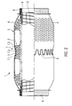
- Fig. 2 shows a second embodiment of a flexible conduit element according to the invention in a partial cross-section.
- Fig. 1 shows the flexible conduit element 1 for an exhaust system for a combustion engine vehicle.
- the flexible conduit is located between the exhaust pipe coming from the engine and a pipe leading to the muffler.
- the pipes and the muffler are not shown in the Figures.
- this arrangement of a flexible conduit element within the exhaust system of a vehicle is known to the skilled person.
- the flexible conduit element comprises a metal bellows member 2 with annular corrugations 3.
- the metal bellows member 2 is surrounded by an outer flexible member 4 which is comprised of a reticulated structure, in particular a net structure of a knitted wire mesh.
- the net structure is visible in Fig. 1 in the lower half, which depicts an outer view of the flexible conduit element.
- the upper half in Fig. 1 shows a cross-section.
- between the wire of the net structure there are openings which lead to a very open structure of the net structure.
- the openings between the wire constitute more than 50%, preferably 75% of the total surface of the essentially cylindrical arrangement of the net structure of the outer flexible member 4.
- the flexible conduit element 1 further comprises a resilient member 5 which is disposed around the outer flexible member 4 and thus also the bellows member 2.
- the resilient member 5 is a spring member which is essentially ring-shaped surrounding the bellows and the outer flexible member. In order to obtain a tensioning force, the resilient member 5 comprises undulations 6 which allow to flex to resilient member 5. Resilient member 5 generates a tensioning force towards the bellows member.
- a spirally-shaped spring element may also be provided, which surrounds the flexible conduit element.
- the resilient member 5 is an engagement with the outer surface of the outer flexible member 4 and biases a section of the outer flexible member 4 towards the bellows member 2.
- the outer flexible member 4 is generally flexible in the axial direction of the flexible conduit element as well as in its circumferential direction. It is generally hose-shaped and extends along the entire length of the corrugations 3 of the bellows member 2. The length is adapted such that it touches in an unextended condition of the flexible conduit element, the bellows member 2 in the area of the resilient member 5 as it is biased towards the bellows member by the resilient member.
- the bellows member 2 comprises corrugations of different radial extension.
- the radial extension of the corrugations increases to a sequence of corrugations 3 of equal height.
- the radial extension of the corrugations is again reduced, such that the corrugations form a groove 7 formed by corrugations of a smaller radial extension 7.1, 7.2 and 7.3.
- the corrugations form a groove 7 formed by corrugations of a smaller radial extension 7.1, 7.2 and 7.3.
- three corrugations form the groove whereas the middle corrugation has the smallest radial extension.
- the resilient member 5 is disposed around this groove 7 and its dimensions are chosen in a way such that the resilient member 5 is more or less received completely within the groove.
- the resilient member 5 pushes the outer flexible member 4 into the groove, such that it touches the tips of at least one or two of the corrugations of reduced radial extension.
- the metal bellows member 2 and the outer flexible member 4 abut each other and are held together by respective two ring-shaped elements, namely an inner ring-shaped element 8 and an outer ring-shaped element 9.
- the two ring-shaped elements 8 and 9 clamp the bellows member 2 and the outer flexible member 4 together in a known manner.
- the outer flexible member 4 receives a shape, where it touches the outer corrugations of the metal bellows at their tips.
- the outer flexible member 4 is flexed and may essentially completely touch the tips of the corrugations 3 of the bellows member 2 also in the areas where the radial extension of the corrugations is essentially constant. The gap will thus disappear.
- the flexible conduit element comprises within the bellows member an inner tube 10 which is comprised of a braided wire mesh.
- the shape of the braided wire mesh is depicted in the upper half of Fig. 1 which is a cross-section and shows the inner tube.
- the inner tube 10 is attached to the inner ring-shaped element 8 by using a clamping ring 11.
- the inner tube 10 is thereby held between the inner ring-shaped element 8 and the clamping ring 11.
- the inner tube 10 which is comprised of a braided wire mesh hose is designed in such a way as it does not touch the corrugations of the bellows member 2 in an unbent condition as depicted in Fig. 1.
- the metal braid of the inner tube is of a completely different design than the design of the outer flexible member 4.
- the tubes of the exhaust gas system When installed in the exhaust system of the vehicle, the tubes of the exhaust gas system are to be received within the inner ring-shaped elements 8 on either side of the flexible conduit element. Exhaust gas is directed through these tubes and also through the inner tube 10 of the flexible conduit element.
- the flexible conduit element 1 allows to absorb rather large movements in-between the two pipes attached to either side of the flexible conduit element.
- vibrations are generated depending on the revolution speed of the engine and the design of the engine for example. In the case of a four-cylinder in-line engine, certain resonant frequencies known to the skilled person are generated.
- the gap When extending the flexible conduit element, the gap will shrink or disappear and the outer flexible will more or less be completely in engagement with the bellows member 2 inducing friction between the bellows member and the outer flexible member, thereby dissipating vibrational energy. Still, the wire mesh structure of the outer flexible member is strong enough to protect the metal bellows.
- the larger traction limit is of significant importance as it allows to provide for more flexibility of the conduit element and also allows to use shorter flexible conduit elements which provide the same traction limit than previously known longer flexible conduit elements. In a given length of the flexible element, this larger traction limit provides better durability to the bellows member and the outer flexible member because those are free of the extreme stress occurring while the structure limit restricts large deflection of the flexible element body.
- the flexible conduit element as depicted in Fig. 1 is used mostly for diesel engines.
- the use of the inner tube using a braided wire mesh is advantageous when using diesel engines.
- the design of the second embodiment is essentially identical to the first embodiment. The only difference is the number of corrugations of smaller radial extension which form the groove 7. In the second embodiment, there are four of such corrugations of which the most inner two corrugations have the same radial extension.
- the second embodiment uses an agrafe-type hose 12, of which in the upper half of Fig. 2 a cross-section is visible.
- the agrafe-type hose comprises spirally-shaped elements, which are connected in a known manner through a hook-like design.
- the agrafe-type hose 12, the bellows member 2 and the outer flexible member 4 are held together by an inner ring-shaped element 8 and an outer ring-shaped element 9.
- the design of the inner ring-shaped element 8 is slightly different compared to the design of the inner ring-shaped element 8 of the first embodiment due to the use of the agrafe-type hose 12.
- the embodiment for using the agrafe-type hose 12 is used for petrol engines.
- the use of the agrafe-type hose 12 allows less axial resistance when extending flexible conduit elements compared to the use of a braided wire mesh-type hose. Due to the design of the agrafe-type hose 12, there is however a very significant tension limit, when the agrafe-type hose is fully extended. Concerning the functioning of the outer flexible member 4, the second embodiment is identical to the first embodiment.
Landscapes
- Engineering & Computer Science (AREA)
- General Engineering & Computer Science (AREA)
- Mechanical Engineering (AREA)
- Chemical & Material Sciences (AREA)
- Combustion & Propulsion (AREA)
- Exhaust Silencers (AREA)
- Ultra Sonic Daignosis Equipment (AREA)
- Endoscopes (AREA)
- Media Introduction/Drainage Providing Device (AREA)
- Joints Allowing Movement (AREA)
Priority Applications (3)
| Application Number | Priority Date | Filing Date | Title |
|---|---|---|---|
| DE602006011165T DE602006011165D1 (de) | 2006-10-02 | 2006-10-02 | Flexibles Leitungselement |
| AT06020733T ATE452281T1 (de) | 2006-10-02 | 2006-10-02 | Flexibles leitungselement |
| EP06020733A EP1908936B1 (fr) | 2006-10-02 | 2006-10-02 | Elément de conduit flexible |
Applications Claiming Priority (1)
| Application Number | Priority Date | Filing Date | Title |
|---|---|---|---|
| EP06020733A EP1908936B1 (fr) | 2006-10-02 | 2006-10-02 | Elément de conduit flexible |
Publications (2)
| Publication Number | Publication Date |
|---|---|
| EP1908936A1 true EP1908936A1 (fr) | 2008-04-09 |
| EP1908936B1 EP1908936B1 (fr) | 2009-12-16 |
Family
ID=37564272
Family Applications (1)
| Application Number | Title | Priority Date | Filing Date |
|---|---|---|---|
| EP06020733A Not-in-force EP1908936B1 (fr) | 2006-10-02 | 2006-10-02 | Elément de conduit flexible |
Country Status (3)
| Country | Link |
|---|---|
| EP (1) | EP1908936B1 (fr) |
| AT (1) | ATE452281T1 (fr) |
| DE (1) | DE602006011165D1 (fr) |
Cited By (8)
| Publication number | Priority date | Publication date | Assignee | Title |
|---|---|---|---|---|
| EP1967783A1 (fr) | 2007-03-09 | 2008-09-10 | Witzenmann GmbH | Elément de conduite flexible |
| DE202010014350U1 (de) | 2010-10-18 | 2010-12-16 | Witzenmann Gmbh | Balg und flexibles Leitungselement mit einem solchen |
| EP2302275A1 (fr) * | 2009-09-29 | 2011-03-30 | Tru-Flex Metal Hose Corp. | Conduit de système d'échappement avec isolation thermique/sonore |
| GB2474683A (en) * | 2009-10-23 | 2011-04-27 | Leyland Trucks Ltd | Pipe unit with flow modifying formations |
| CN105822866A (zh) * | 2016-03-18 | 2016-08-03 | 石家庄巨力科技有限公司 | 一种轴向型防阻降噪膨胀节 |
| EP3091267A1 (fr) | 2015-05-04 | 2016-11-09 | Sjm Co., Ltd. | Élément de conduite flexible |
| EP3091264A1 (fr) | 2015-05-04 | 2016-11-09 | Sjm Co., Ltd. | Élément de conduite flexible |
| EP3091263A1 (fr) | 2015-05-04 | 2016-11-09 | Sjm Co., Ltd. | Élément de conduite flexible |
Citations (6)
| Publication number | Priority date | Publication date | Assignee | Title |
|---|---|---|---|---|
| EP0410089A1 (fr) * | 1989-07-26 | 1991-01-30 | Witzenmann GmbH Metallschlauch-Fabrik Pforzheim | Elément de conduite flexible pour tuyaux d'échappement de moteurs de véhicules à combustion interne |
| US5456291A (en) * | 1987-09-01 | 1995-10-10 | Iwk Regler Und Kompensatoren Gmbh | Conduit metallic knit element for exhaust gas systems |
| EP0860590A1 (fr) * | 1997-02-25 | 1998-08-26 | FLEXIDER S.p.A. | Tuyau ondulé flexible pour désaccoupler les tuyaux d'échappement d'un véhicule motorisé |
| DE202004008089U1 (de) * | 2004-05-21 | 2004-07-29 | Witzenmann Gmbh | Flexibles Leitungselement für Abgasleitungen |
| EP1576263A1 (fr) | 2003-02-19 | 2005-09-21 | Witzenmann GmbH | Element de conduit flexible |
| DE102004041348A1 (de) | 2004-07-20 | 2006-02-16 | Sjm Co. Ltd., Ansan | Flexibles Rohr für ein Abgasrohr eines Kraftfahrzeugs |
-
2006
- 2006-10-02 DE DE602006011165T patent/DE602006011165D1/de active Active
- 2006-10-02 AT AT06020733T patent/ATE452281T1/de not_active IP Right Cessation
- 2006-10-02 EP EP06020733A patent/EP1908936B1/fr not_active Not-in-force
Patent Citations (6)
| Publication number | Priority date | Publication date | Assignee | Title |
|---|---|---|---|---|
| US5456291A (en) * | 1987-09-01 | 1995-10-10 | Iwk Regler Und Kompensatoren Gmbh | Conduit metallic knit element for exhaust gas systems |
| EP0410089A1 (fr) * | 1989-07-26 | 1991-01-30 | Witzenmann GmbH Metallschlauch-Fabrik Pforzheim | Elément de conduite flexible pour tuyaux d'échappement de moteurs de véhicules à combustion interne |
| EP0860590A1 (fr) * | 1997-02-25 | 1998-08-26 | FLEXIDER S.p.A. | Tuyau ondulé flexible pour désaccoupler les tuyaux d'échappement d'un véhicule motorisé |
| EP1576263A1 (fr) | 2003-02-19 | 2005-09-21 | Witzenmann GmbH | Element de conduit flexible |
| DE202004008089U1 (de) * | 2004-05-21 | 2004-07-29 | Witzenmann Gmbh | Flexibles Leitungselement für Abgasleitungen |
| DE102004041348A1 (de) | 2004-07-20 | 2006-02-16 | Sjm Co. Ltd., Ansan | Flexibles Rohr für ein Abgasrohr eines Kraftfahrzeugs |
Cited By (12)
| Publication number | Priority date | Publication date | Assignee | Title |
|---|---|---|---|---|
| EP1967783A1 (fr) | 2007-03-09 | 2008-09-10 | Witzenmann GmbH | Elément de conduite flexible |
| EP2302275A1 (fr) * | 2009-09-29 | 2011-03-30 | Tru-Flex Metal Hose Corp. | Conduit de système d'échappement avec isolation thermique/sonore |
| US9261216B2 (en) | 2009-09-29 | 2016-02-16 | Tru-Flex, Llc | Exhaust system conduit with thermal/noise insulation |
| GB2474683A (en) * | 2009-10-23 | 2011-04-27 | Leyland Trucks Ltd | Pipe unit with flow modifying formations |
| GB2474683B (en) * | 2009-10-23 | 2015-12-30 | Leyland Trucks Ltd | Pipe unit |
| DE202010014350U1 (de) | 2010-10-18 | 2010-12-16 | Witzenmann Gmbh | Balg und flexibles Leitungselement mit einem solchen |
| EP2441996A2 (fr) | 2010-10-18 | 2012-04-18 | Witzenmann GmbH | Poutre et élément de guidage flexible doté de celle-ci |
| EP3091267A1 (fr) | 2015-05-04 | 2016-11-09 | Sjm Co., Ltd. | Élément de conduite flexible |
| EP3091264A1 (fr) | 2015-05-04 | 2016-11-09 | Sjm Co., Ltd. | Élément de conduite flexible |
| EP3091263A1 (fr) | 2015-05-04 | 2016-11-09 | Sjm Co., Ltd. | Élément de conduite flexible |
| CN105822866A (zh) * | 2016-03-18 | 2016-08-03 | 石家庄巨力科技有限公司 | 一种轴向型防阻降噪膨胀节 |
| CN105822866B (zh) * | 2016-03-18 | 2018-06-26 | 石家庄巨力科技有限公司 | 一种轴向型防阻降噪膨胀节 |
Also Published As
| Publication number | Publication date |
|---|---|
| ATE452281T1 (de) | 2010-01-15 |
| DE602006011165D1 (de) | 2010-01-28 |
| EP1908936B1 (fr) | 2009-12-16 |
Similar Documents
| Publication | Publication Date | Title |
|---|---|---|
| US7650912B2 (en) | Flexible conduit element | |
| EP1908936B1 (fr) | Elément de conduit flexible | |
| KR100906552B1 (ko) | 자동차 배기관용 플렉시블 튜브 | |
| KR101862841B1 (ko) | 가요성 도관 요소 | |
| JP6078033B2 (ja) | 自動車の排気管用可撓性導管 | |
| KR100353123B1 (ko) | 자동차 배기관용 연결구 | |
| US6612342B2 (en) | Flexible pipe element | |
| US6062268A (en) | Tube element with one metal bellows | |
| US5437479A (en) | Flexible connection arrangement for the two pipe portions particularly for motor vehicle exhausts | |
| US5901754A (en) | Flexible fluid conduit element with a metal bellows | |
| US5967193A (en) | Flexible pipe unit for use in exhaust pipe line of automotive engine | |
| US6220023B1 (en) | Line element with damping, particularly for exhaust pipes of internal combustion engines in motor vehicles | |
| US7444806B2 (en) | Exhaust system component | |
| JP2008088954A (ja) | 排気管の接続装置 | |
| KR100602770B1 (ko) | 자동차 배기관용 플렉시블 튜브 | |
| KR20190008336A (ko) | 충격 완화 가요성 파이프 | |
| US9581070B2 (en) | Uncoupling element | |
| US5956950A (en) | Arrangement for isolating torsional vibration | |
| JP2009144520A (ja) | 可撓性導管 | |
| KR200183322Y1 (ko) | 자동차 배기관용 벨로우즈 | |
| KR200183321Y1 (ko) | 자동차 배기관용 벨로우즈 | |
| GB1575892A (en) | Flexible pipe for exhaus gas pipes of internal combustion engines | |
| KR200313051Y1 (ko) | 엔진 배기관용 디커플러 | |
| KR20030060158A (ko) | 자동차 배기관용 플렉시블 튜브 | |
| KR20010114027A (ko) | 자동차 배기관용 연결구 |
Legal Events
| Date | Code | Title | Description |
|---|---|---|---|
| PUAI | Public reference made under article 153(3) epc to a published international application that has entered the european phase |
Free format text: ORIGINAL CODE: 0009012 |
|
| AK | Designated contracting states |
Kind code of ref document: A1 Designated state(s): AT BE BG CH CY CZ DE DK EE ES FI FR GB GR HU IE IS IT LI LT LU LV MC NL PL PT RO SE SI SK TR |
|
| AX | Request for extension of the european patent |
Extension state: AL BA HR MK RS |
|
| 17P | Request for examination filed |
Effective date: 20081009 |
|
| 17Q | First examination report despatched |
Effective date: 20081106 |
|
| AKX | Designation fees paid |
Designated state(s): AT BE BG CH CY CZ DE DK EE ES FI FR GB GR HU IE IS IT LI LT LU LV MC NL PL PT RO SE SI SK TR |
|
| GRAP | Despatch of communication of intention to grant a patent |
Free format text: ORIGINAL CODE: EPIDOSNIGR1 |
|
| GRAS | Grant fee paid |
Free format text: ORIGINAL CODE: EPIDOSNIGR3 |
|
| GRAA | (expected) grant |
Free format text: ORIGINAL CODE: 0009210 |
|
| AK | Designated contracting states |
Kind code of ref document: B1 Designated state(s): AT BE BG CH CY CZ DE DK EE ES FI FR GB GR HU IE IS IT LI LT LU LV MC NL PL PT RO SE SI SK TR |
|
| REG | Reference to a national code |
Ref country code: GB Ref legal event code: FG4D |
|
| REG | Reference to a national code |
Ref country code: CH Ref legal event code: EP |
|
| REG | Reference to a national code |
Ref country code: IE Ref legal event code: FG4D |
|
| REF | Corresponds to: |
Ref document number: 602006011165 Country of ref document: DE Date of ref document: 20100128 Kind code of ref document: P |
|
| REG | Reference to a national code |
Ref country code: SE Ref legal event code: TRGR |
|
| REG | Reference to a national code |
Ref country code: NL Ref legal event code: VDEP Effective date: 20091216 |
|
| PG25 | Lapsed in a contracting state [announced via postgrant information from national office to epo] |
Ref country code: FI Free format text: LAPSE BECAUSE OF FAILURE TO SUBMIT A TRANSLATION OF THE DESCRIPTION OR TO PAY THE FEE WITHIN THE PRESCRIBED TIME-LIMIT Effective date: 20091216 Ref country code: LT Free format text: LAPSE BECAUSE OF FAILURE TO SUBMIT A TRANSLATION OF THE DESCRIPTION OR TO PAY THE FEE WITHIN THE PRESCRIBED TIME-LIMIT Effective date: 20091216 |
|
| LTIE | Lt: invalidation of european patent or patent extension |
Effective date: 20091216 |
|
| PG25 | Lapsed in a contracting state [announced via postgrant information from national office to epo] |
Ref country code: PL Free format text: LAPSE BECAUSE OF FAILURE TO SUBMIT A TRANSLATION OF THE DESCRIPTION OR TO PAY THE FEE WITHIN THE PRESCRIBED TIME-LIMIT Effective date: 20091216 Ref country code: SI Free format text: LAPSE BECAUSE OF FAILURE TO SUBMIT A TRANSLATION OF THE DESCRIPTION OR TO PAY THE FEE WITHIN THE PRESCRIBED TIME-LIMIT Effective date: 20091216 Ref country code: LV Free format text: LAPSE BECAUSE OF FAILURE TO SUBMIT A TRANSLATION OF THE DESCRIPTION OR TO PAY THE FEE WITHIN THE PRESCRIBED TIME-LIMIT Effective date: 20091216 |
|
| PG25 | Lapsed in a contracting state [announced via postgrant information from national office to epo] |
Ref country code: AT Free format text: LAPSE BECAUSE OF FAILURE TO SUBMIT A TRANSLATION OF THE DESCRIPTION OR TO PAY THE FEE WITHIN THE PRESCRIBED TIME-LIMIT Effective date: 20091216 |
|
| PG25 | Lapsed in a contracting state [announced via postgrant information from national office to epo] |
Ref country code: RO Free format text: LAPSE BECAUSE OF FAILURE TO SUBMIT A TRANSLATION OF THE DESCRIPTION OR TO PAY THE FEE WITHIN THE PRESCRIBED TIME-LIMIT Effective date: 20091216 Ref country code: PT Free format text: LAPSE BECAUSE OF FAILURE TO SUBMIT A TRANSLATION OF THE DESCRIPTION OR TO PAY THE FEE WITHIN THE PRESCRIBED TIME-LIMIT Effective date: 20100416 Ref country code: NL Free format text: LAPSE BECAUSE OF FAILURE TO SUBMIT A TRANSLATION OF THE DESCRIPTION OR TO PAY THE FEE WITHIN THE PRESCRIBED TIME-LIMIT Effective date: 20091216 Ref country code: IS Free format text: LAPSE BECAUSE OF FAILURE TO SUBMIT A TRANSLATION OF THE DESCRIPTION OR TO PAY THE FEE WITHIN THE PRESCRIBED TIME-LIMIT Effective date: 20100416 Ref country code: ES Free format text: LAPSE BECAUSE OF FAILURE TO SUBMIT A TRANSLATION OF THE DESCRIPTION OR TO PAY THE FEE WITHIN THE PRESCRIBED TIME-LIMIT Effective date: 20100327 Ref country code: EE Free format text: LAPSE BECAUSE OF FAILURE TO SUBMIT A TRANSLATION OF THE DESCRIPTION OR TO PAY THE FEE WITHIN THE PRESCRIBED TIME-LIMIT Effective date: 20091216 Ref country code: BG Free format text: LAPSE BECAUSE OF FAILURE TO SUBMIT A TRANSLATION OF THE DESCRIPTION OR TO PAY THE FEE WITHIN THE PRESCRIBED TIME-LIMIT Effective date: 20100316 |
|
| PG25 | Lapsed in a contracting state [announced via postgrant information from national office to epo] |
Ref country code: CZ Free format text: LAPSE BECAUSE OF FAILURE TO SUBMIT A TRANSLATION OF THE DESCRIPTION OR TO PAY THE FEE WITHIN THE PRESCRIBED TIME-LIMIT Effective date: 20091216 Ref country code: SK Free format text: LAPSE BECAUSE OF FAILURE TO SUBMIT A TRANSLATION OF THE DESCRIPTION OR TO PAY THE FEE WITHIN THE PRESCRIBED TIME-LIMIT Effective date: 20091216 Ref country code: BE Free format text: LAPSE BECAUSE OF FAILURE TO SUBMIT A TRANSLATION OF THE DESCRIPTION OR TO PAY THE FEE WITHIN THE PRESCRIBED TIME-LIMIT Effective date: 20091216 |
|
| PLBE | No opposition filed within time limit |
Free format text: ORIGINAL CODE: 0009261 |
|
| STAA | Information on the status of an ep patent application or granted ep patent |
Free format text: STATUS: NO OPPOSITION FILED WITHIN TIME LIMIT |
|
| PG25 | Lapsed in a contracting state [announced via postgrant information from national office to epo] |
Ref country code: CY Free format text: LAPSE BECAUSE OF FAILURE TO SUBMIT A TRANSLATION OF THE DESCRIPTION OR TO PAY THE FEE WITHIN THE PRESCRIBED TIME-LIMIT Effective date: 20091216 Ref country code: GR Free format text: LAPSE BECAUSE OF FAILURE TO SUBMIT A TRANSLATION OF THE DESCRIPTION OR TO PAY THE FEE WITHIN THE PRESCRIBED TIME-LIMIT Effective date: 20100317 |
|
| 26N | No opposition filed |
Effective date: 20100917 |
|
| PG25 | Lapsed in a contracting state [announced via postgrant information from national office to epo] |
Ref country code: DK Free format text: LAPSE BECAUSE OF FAILURE TO SUBMIT A TRANSLATION OF THE DESCRIPTION OR TO PAY THE FEE WITHIN THE PRESCRIBED TIME-LIMIT Effective date: 20091216 |
|
| PG25 | Lapsed in a contracting state [announced via postgrant information from national office to epo] |
Ref country code: MC Free format text: LAPSE BECAUSE OF NON-PAYMENT OF DUE FEES Effective date: 20101031 |
|
| REG | Reference to a national code |
Ref country code: CH Ref legal event code: PL |
|
| PG25 | Lapsed in a contracting state [announced via postgrant information from national office to epo] |
Ref country code: CH Free format text: LAPSE BECAUSE OF NON-PAYMENT OF DUE FEES Effective date: 20101031 Ref country code: LI Free format text: LAPSE BECAUSE OF NON-PAYMENT OF DUE FEES Effective date: 20101031 |
|
| PG25 | Lapsed in a contracting state [announced via postgrant information from national office to epo] |
Ref country code: IE Free format text: LAPSE BECAUSE OF NON-PAYMENT OF DUE FEES Effective date: 20101002 |
|
| PG25 | Lapsed in a contracting state [announced via postgrant information from national office to epo] |
Ref country code: HU Free format text: LAPSE BECAUSE OF FAILURE TO SUBMIT A TRANSLATION OF THE DESCRIPTION OR TO PAY THE FEE WITHIN THE PRESCRIBED TIME-LIMIT Effective date: 20100617 Ref country code: LU Free format text: LAPSE BECAUSE OF NON-PAYMENT OF DUE FEES Effective date: 20101002 |
|
| PG25 | Lapsed in a contracting state [announced via postgrant information from national office to epo] |
Ref country code: TR Free format text: LAPSE BECAUSE OF FAILURE TO SUBMIT A TRANSLATION OF THE DESCRIPTION OR TO PAY THE FEE WITHIN THE PRESCRIBED TIME-LIMIT Effective date: 20091216 |
|
| REG | Reference to a national code |
Ref country code: FR Ref legal event code: PLFP Year of fee payment: 10 |
|
| REG | Reference to a national code |
Ref country code: FR Ref legal event code: PLFP Year of fee payment: 11 |
|
| REG | Reference to a national code |
Ref country code: FR Ref legal event code: PLFP Year of fee payment: 12 |
|
| REG | Reference to a national code |
Ref country code: FR Ref legal event code: PLFP Year of fee payment: 13 |
|
| PGFP | Annual fee paid to national office [announced via postgrant information from national office to epo] |
Ref country code: GB Payment date: 20211023 Year of fee payment: 16 Ref country code: SE Payment date: 20211023 Year of fee payment: 16 Ref country code: DE Payment date: 20211026 Year of fee payment: 16 |
|
| PGFP | Annual fee paid to national office [announced via postgrant information from national office to epo] |
Ref country code: IT Payment date: 20211029 Year of fee payment: 16 Ref country code: FR Payment date: 20211023 Year of fee payment: 16 |
|
| REG | Reference to a national code |
Ref country code: DE Ref legal event code: R119 Ref document number: 602006011165 Country of ref document: DE |
|
| REG | Reference to a national code |
Ref country code: SE Ref legal event code: EUG |
|
| GBPC | Gb: european patent ceased through non-payment of renewal fee |
Effective date: 20221002 |
|
| PG25 | Lapsed in a contracting state [announced via postgrant information from national office to epo] |
Ref country code: FR Free format text: LAPSE BECAUSE OF NON-PAYMENT OF DUE FEES Effective date: 20221031 Ref country code: DE Free format text: LAPSE BECAUSE OF NON-PAYMENT OF DUE FEES Effective date: 20230503 |
|
| PG25 | Lapsed in a contracting state [announced via postgrant information from national office to epo] |
Ref country code: SE Free format text: LAPSE BECAUSE OF NON-PAYMENT OF DUE FEES Effective date: 20221003 |
|
| PG25 | Lapsed in a contracting state [announced via postgrant information from national office to epo] |
Ref country code: IT Free format text: LAPSE BECAUSE OF NON-PAYMENT OF DUE FEES Effective date: 20221002 Ref country code: GB Free format text: LAPSE BECAUSE OF NON-PAYMENT OF DUE FEES Effective date: 20221002 |