EP1908914A1 - Method of mounting plate glass body - Google Patents
Method of mounting plate glass body Download PDFInfo
- Publication number
- EP1908914A1 EP1908914A1 EP06757038A EP06757038A EP1908914A1 EP 1908914 A1 EP1908914 A1 EP 1908914A1 EP 06757038 A EP06757038 A EP 06757038A EP 06757038 A EP06757038 A EP 06757038A EP 1908914 A1 EP1908914 A1 EP 1908914A1
- Authority
- EP
- European Patent Office
- Prior art keywords
- glass plate
- plate body
- sash
- pin
- synthetic resin
- Prior art date
- Legal status (The legal status is an assumption and is not a legal conclusion. Google has not performed a legal analysis and makes no representation as to the accuracy of the status listed.)
- Withdrawn
Links
- 238000000034 method Methods 0.000 title claims abstract description 29
- 239000005357 flat glass Substances 0.000 title description 2
- 239000011521 glass Substances 0.000 claims abstract description 117
- 229920003002 synthetic resin Polymers 0.000 claims abstract description 36
- 239000000057 synthetic resin Substances 0.000 claims abstract description 36
- 239000002184 metal Substances 0.000 description 8
- 230000002093 peripheral effect Effects 0.000 description 6
- 238000010276 construction Methods 0.000 description 5
- 239000000463 material Substances 0.000 description 5
- 239000013013 elastic material Substances 0.000 description 4
- 238000003780 insertion Methods 0.000 description 4
- 230000037431 insertion Effects 0.000 description 4
- 229910001369 Brass Inorganic materials 0.000 description 1
- 229910000975 Carbon steel Inorganic materials 0.000 description 1
- 239000000853 adhesive Substances 0.000 description 1
- 239000010951 brass Substances 0.000 description 1
- 239000010962 carbon steel Substances 0.000 description 1
- 239000011248 coating agent Substances 0.000 description 1
- 238000000576 coating method Methods 0.000 description 1
- 239000003086 colorant Substances 0.000 description 1
- 238000007796 conventional method Methods 0.000 description 1
- 238000006073 displacement reaction Methods 0.000 description 1
- 230000000694 effects Effects 0.000 description 1
- 230000002349 favourable effect Effects 0.000 description 1
- 239000005340 laminated glass Substances 0.000 description 1
- 235000015250 liver sausages Nutrition 0.000 description 1
- 238000012986 modification Methods 0.000 description 1
- 230000004048 modification Effects 0.000 description 1
- 229920005989 resin Polymers 0.000 description 1
- 239000011347 resin Substances 0.000 description 1
- 238000007789 sealing Methods 0.000 description 1
- 239000010935 stainless steel Substances 0.000 description 1
- 229910001220 stainless steel Inorganic materials 0.000 description 1
- 239000002023 wood Substances 0.000 description 1
Images


Classifications
-
- E—FIXED CONSTRUCTIONS
- E06—DOORS, WINDOWS, SHUTTERS, OR ROLLER BLINDS IN GENERAL; LADDERS
- E06B—FIXED OR MOVABLE CLOSURES FOR OPENINGS IN BUILDINGS, VEHICLES, FENCES OR LIKE ENCLOSURES IN GENERAL, e.g. DOORS, WINDOWS, BLINDS, GATES
- E06B3/00—Window sashes, door leaves, or like elements for closing wall or like openings; Layout of fixed or moving closures, e.g. windows in wall or like openings; Features of rigidly-mounted outer frames relating to the mounting of wing frames
- E06B3/54—Fixing of glass panes or like plates
- E06B3/5481—Fixing of glass panes or like plates by means of discrete fixing elements, e.g. glazing clips, glaziers points
Definitions
- the present invention relates to a method of mounting a glass plate body, including the steps of fitting the glass plate body to a sash (e.g. a wooden sash), fixing the glass plate body to the sash with a fixing member (e.g. a nail), and applying an amount of putty to the entire periphery of the glass plate body for fixing it in a sealed state.
- a sash e.g. a wooden sash
- a fixing member e.g. a nail
- an amount of putty 4 is applied as a thin layer to a groove wall 6a of a groove portion 6 of a sash 2.
- a glass plate body 5 is fitted into the groove portion 6, with placing an outer peripheral edge of one face of the glass plate body 5 in contact with the putty 4 disposed at the groove portion 6a.
- a metal fixing member 20 is stuck into a groove bottom 6b at a border between this groove bottom 6b and the other face of the glass plate body 5 so as to place the edge of the other face of the glass plate body 5 in contact with a lateral face of the metal fixing member 20, thereby to provide a temporary fixation.
- Non-Patent Document 1 Architectural Institute of Japan: "Manual of Construction Work Standards: Commentary: JASS17 Glazing Work” Gihodo Shuppan Co., Ltd. April 30, 1999, 3rd Edition, 4th Print: p. 78 .
- the glass plate body is mounted to the sash, with the surface of the metal fitting tool and a portion of the edge of the glass plate body being in contact with each other.
- a crack or a chipping may occur mainly at the fixed portion of the glass plate body. Or, even worse, the glass plate body might be broken and become disengaged from the sash.
- an object of the present invention is to provide a method of mounting a glass plate body, which can effectively restrict such damage in the glass plate body even in the event of application of an external force/vibration or the like under the fitted condition of the glass plate body to the sash.
- the method is characterized in that the fixing member comprises a pin including a leg portion capable of entering the sash to be fixed thereto and a supporting portion capable of supporting an edge of the glass plate body, the supporting portion having a synthetic resin portion cushionable relative to the edge of glass plate body; and the pin is fixed to the sash so that the synthetic resin portion is placed in contact with the edge of glass plate body fitted to the sash.
- the edge of the glass plate body is fixed by the supporting portion of the pin via the cushionable synthetic resin portion, so that it is possible to maintain an mounted condition free from occurrence of damage to the edge of glass plate body due to e.g. hitting of a hard object thereto. That is, the glass plate body is fixed to the sash under the stable condition realized by the cooperative function of the fixing member and the putty, and at the same time, there is no direct contact of any hard portion of the pin to the edge of glass plate body.
- the problem with the convention i.e. the occurrence of stress concentration at the fixed portion of the edge of glass plate body, has been overcome.
- the glass plate body can be used for a longer period of time. Further, breakage can be restricted even in case a glass plate body having lower strength than the standard glass plate body (e.g. a glass plate body formed of low-strength glass, a thin glass plate body, a glass glazing with high heat-insulating performance comprised of a plurality of thin glass plates assembled together with a gap therebetween) is installed to a sash.
- a glass plate body having lower strength than the standard glass plate body e.g. a glass plate body formed of low-strength glass, a thin glass plate body, a glass glazing with high heat-insulating performance comprised of a plurality of thin glass plates assembled together with a gap therebetween
- the method is characterized in that wherein the fixing member comprises a pair of engaging sheets having engaging faces engageable with each other; one of the engaging sheets is fixed to at least a portion of a receiving face of the sash for the glass plate body; the other engaging sheet is fixed to a portion of the glass plate body opposed to the portion to which the one engaging sheet is fixed; and the glass plate body is fixed to the sash so that the engaging sheets engage with each other.
- the fixing member comprises a pair of engaging sheets having engaging faces engageable with each other; one of the engaging sheets is fixed to at least a portion of a receiving face of the sash for the glass plate body; the other engaging sheet is fixed to a portion of the glass plate body opposed to the portion to which the one engaging sheet is fixed; and the glass plate body is fixed to the sash so that the engaging sheets engage with each other.
- the glass plate body mounted to the sash has its edge fixed to the sash with the putty and the pair of engaging sheets, so that it is possible to maintain a favorable condition free from occurrence of damage to the edge of glass plate body due to e.g. hitting of a hard object thereto.
- the glass plate body is fixed to the sash under the stable condition realized by the cooperative function of the pair of engaging sheets and the putty, and at the same time, unlike the convention, there is no direct contact of the hard portion of the metal fixing member with the edge of glass plate body. Hence, the problem of occurrence of stress concentration at the fixed portion of the edge of glass plate body, has been overcome.
- the glass plate body can be used for a longer period of time. Further, breakage can be restricted even in case a glass plate body having lower strength than the standard glass plate body (e.g. a glass plate body formed of low-strength glass, a thin glass plate body, a glass glazing with high heat-insulating performance comprised of a plurality of thin glass plates assembled together with a gap therebetween) is installed to a sash.
- a glass plate body having lower strength than the standard glass plate body e.g. a glass plate body formed of low-strength glass, a thin glass plate body, a glass glazing with high heat-insulating performance comprised of a plurality of thin glass plates assembled together with a gap therebetween
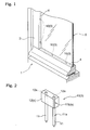
- Figs. 1 through 4 show a sash door 1 constructed with using a method of mounting a glass plate body according to the present invention.
- the sash door 1 includes a sash 2, and a glass plate body 5 mounted to the sash 2 with using a plurality of fixing members 3 and an amount of putty 4.
- the sash 2 is formed of wood material and comprises an assembly of an upper edge frame member forming an outer periphery of the sash door 1, a pair of side edge frame members, and a lower edge frame member, assembled together in the form of a rectangle as shown.
- each frame member As shown in Fig. 3 , at a portion of each frame member corresponding to an inner peripheral face of the sash, there is formed a groove portion 6 into which the plate glass body 5 can be fitted.
- this groove portion 6 there is provided a groove wall 6a only on one of the front and rear faces of the door, so that this groove wall 6a may receive an edge of the glass plate body 5 which is fitted into the groove portion 6 from the other of the front and rear faces of the door.
- a groove bottom 6b of the groove portion 6 can receive the fixing members 3 after the fitting of the glass plate body 5 into the groove portion 6.
- the glass plate body 5 is exemplified by a double glazing 5A which uses thin glass plates, but provides high heat-insulating effect.
- the double glazing 5A comprises a pair of glass plates 7 disposed side by side with a gap 8 therebetween, with the gap 8 being sealed by a seal portion 9 provided along the outer periphery of the glazing.
- the outer perimeter edge of the double glazing 5A is provided with a resin coating expected to provide a protecting function.
- the gap 8 will be evacuated.
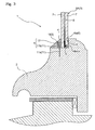
- the fixing member 3 as shown in Fig. 3 , is constructed as a pin 10 which can be struck into and fixed to the groove bottom 6b of the sash 2.
- the pin 10 comprises a plurality of pin bodies 11 formed of a metal such as stainless steel, brass, carbon steel, etc and a synthetic resin portion 12 which can be engaged on one longitudinal end of the respective pin body 11. Then, by striking the pin 10 into the groove bottom 6b of the sash 2, leg portions 11a as lower portions of the pin bodies 11 will advance into the sash 2 to be fixed therein.
- each pin body 11 When the fixing member 3 is fixed to the sash 2, the upper portion of each pin body 11 is engaged within the synthetic resin portion 12, thereby preventing direct contact of the pin body 11 with the glass pate body 5, so that the glass plate body 5 can be supported in a cushionable manner.
- the synthetic resin portion 12 employs, preferably, a material having oil resistance, since this portion is to be placed in contact with the putty. Its shape is exemplified by a rectangular parallelopiped as shown in Fig. 2 , in this embodiment.
- the synthetic resin portion 12 defines insertion holes 12a formed separate from each other for allowing insertion of the respective pin bodies 11.
- the height of the synthetic resin portion 12 will be set to be greater than the above-described step between the plate edges.
- the height of the synthetic resin portion 12 should be set so as to allow the two glass plates 7 to be effectively bound between the groove wall 6a and the synthetic resin portion 12. Therefore, it becomes possible to support the glass plates 7 even more firmly.
- the pin body portion 11b on which the synthetic resin portion 12 is engaged is referred to as "supporting portion (s)".
- the finished appearance after the mounting of the glass plate body 5 to the sash 2 differs in no way from that of the conventional art. And, even when an external force such as vibration is applied to the sash door 1, as the outer peripheral edge of the glass plate body 5 is gently supported, it is possible to prevent generation of breakage or crack therein; hence, durability of the sash door 1 can be improved.
- the fixing member 3 employed in this embodiment instead of the pin 10 described in the foregoing embodiment, comprises a pair of magic tapes ("Magic Tape” registered trademark) (an example of engaging sheets 13) 13A having engaging surfaces (k) engageable with each other, as shown in Figs. 5 and 6 .
- Magic Tape registered trademark
- a magic tape 13Aa of one of the pair of magic tapes 13A is fixed by such means as adhesion.
- the other magic tape 13Ab is fixed by such means as adhesion.
- the double glazing 5A is fitted to the sash 2 so as to allow engagement between the magic tapes, and then the putty 4 is charged into the groove portion 6 for fixation.
- an amount of putty 4 is applied in advance in the form of a thin layer to the groove wall 6a between the one side magic tapes 13Aa disposed adjacent in the peripheral direction of the sash 2.
- the finished appearance after the mounting of the glass plate body 5 to the sash 2 differs in no way from that of the conventional art. And, even when an external force such as vibration is applied to the sash door 1, as the outer peripheral edge of the glass plate body 5 is gently supported, it is possible to prevent generation of breakage or crack therein; hence, durability of the sash door 1 can be improved.
- the present invention may be used in a method of mounting a glass plate body, comprising the steps of fitting the glass plate body to a sash, fixing the glass plate body to the sash with a fixing member and applying an amount of putty to the entire periphery of the glass plate body for fixing the body in a sealed state.
Landscapes
- Engineering & Computer Science (AREA)
- Civil Engineering (AREA)
- Structural Engineering (AREA)
- Securing Of Glass Panes Or The Like (AREA)
Abstract
In a method of mounting a glass plate body, including the steps of fitting the glass plate body 5 to a sash 2, fixing the glass plate body 5 to the sash 2 with a fixing member 3, and applying an amount of putty 4 to the entire periphery of the glass plate body 5 for fixing it in a sealed state, the fixing member 3 includes a pin 10 having a leg portion 11a capable of entering the sash 2 to be fixed thereto and a supporting portion (s) capable of supporting an edge of the glass plate body 5. The supporting portion (s) has a synthetic resin portion 12 cushionable relative to the glass plate body 5 edge. The pin 10 is fixed to the sash 2 so that the synthetic resin portion 12 is placed in contact with the glass plate body 5 edge fitted to the sash 2.
Description
- The present invention relates to a method of mounting a glass plate body, including the steps of fitting the glass plate body to a sash (e.g. a wooden sash), fixing the glass plate body to the sash with a fixing member (e.g. a nail), and applying an amount of putty to the entire periphery of the glass plate body for fixing it in a sealed state.
- Conventionally, as this type of method of mounting a glass plate body, there is known a method using a metal fixing member such as a nail, a wire clip, etc.
- For instance, as shown in
Fig. 7 , an amount ofputty 4 is applied as a thin layer to agroove wall 6a of agroove portion 6 of asash 2. Then, under this condition, aglass plate body 5 is fitted into thegroove portion 6, with placing an outer peripheral edge of one face of theglass plate body 5 in contact with theputty 4 disposed at thegroove portion 6a. Under this condition, ametal fixing member 20 is stuck into agroove bottom 6b at a border between thisgroove bottom 6b and the other face of theglass plate body 5 so as to place the edge of the other face of theglass plate body 5 in contact with a lateral face of themetal fixing member 20, thereby to provide a temporary fixation. - Thereafter, an additional amount of
putty 4 is charged and applied along the entire periphery of thesash 2 on the other side of theglass plate body 5 at thegroove portion 6 in such a manner as not to form any gap therebetween, thereby to provide a permanent fixation (see e.g. Non-Patent Document 1). - Non-Patent Document 1: Architectural Institute of Japan: "Manual of Construction Work Standards: Commentary: JASS17 Glazing Work" Gihodo Shuppan Co., Ltd. April 30, 1999, 3rd Edition, 4th Print: p. 78.
- According to the conventional method of mounting a glass plate body, the glass plate body is mounted to the sash, with the surface of the metal fitting tool and a portion of the edge of the glass plate body being in contact with each other.
- In the above, if e.g. a force/vibration due to an earthquake, wind, sound, etc. is applied to the glass plate body and/or the sash, this tends to invite stress concentration at fixed portions which are the contacting portions between the glass plate body and the fixing member.
- As a result, a crack or a chipping may occur mainly at the fixed portion of the glass plate body. Or, even worse, the glass plate body might be broken and become disengaged from the sash.
- In view of the above, an object of the present invention is to provide a method of mounting a glass plate body, which can effectively restrict such damage in the glass plate body even in the event of application of an external force/vibration or the like under the fitted condition of the glass plate body to the sash.
- For achieving the above-noted object, according to a first characterizing feature of the inventive method of mounting a glass plate body, in the method including the steps of fitting the glass plate body to a sash, fixing the glass plate body to the sash with a fixing member, and applying an amount of putty to the entire periphery of the glass plate body for fixing it in a sealed state, the method is characterized in that the fixing member comprises a pin including a leg portion capable of entering the sash to be fixed thereto and a supporting portion capable of supporting an edge of the glass plate body, the supporting portion having a synthetic resin portion cushionable relative to the edge of glass plate body; and the pin is fixed to the sash so that the synthetic resin portion is placed in contact with the edge of glass plate body fitted to the sash.
- With the above-described first characterizing feature, when the glass plate body is mounted to the sash, the edge of the glass plate body is fixed by the supporting portion of the pin via the cushionable synthetic resin portion, so that it is possible to maintain an mounted condition free from occurrence of damage to the edge of glass plate body due to e.g. hitting of a hard object thereto. That is, the glass plate body is fixed to the sash under the stable condition realized by the cooperative function of the fixing member and the putty, and at the same time, there is no direct contact of any hard portion of the pin to the edge of glass plate body. Hence, the problem with the convention, i.e. the occurrence of stress concentration at the fixed portion of the edge of glass plate body, has been overcome.
- Consequently, even in the event of application of an external force/vibration under the condition of the glass plate body being mounted to the sash, break or crack at the fixed portion of the glass plate body hardly occurs, and such inconvenience as the damage of the glass plate body and/or subsequent accidental disengagement thereof can be readily prevented.
- Therefore, according to the above-described construction, the glass plate body can be used for a longer period of time. Further, breakage can be restricted even in case a glass plate body having lower strength than the standard glass plate body (e.g. a glass plate body formed of low-strength glass, a thin glass plate body, a glass glazing with high heat-insulating performance comprised of a plurality of thin glass plates assembled together with a gap therebetween) is installed to a sash.
- According to a second characterizing of the inventive method of mounting a glass plate body, in the method including the steps of fitting the glass plate body to a sash, fixing the glass plate body to the sash with a fixing member, and applying an amount of putty to the entire periphery of the glass plate body for fixing it in a sealed state, the method is characterized in that wherein the fixing member comprises a pair of engaging sheets having engaging faces engageable with each other; one of the engaging sheets is fixed to at least a portion of a receiving face of the sash for the glass plate body; the other engaging sheet is fixed to a portion of the glass plate body opposed to the portion to which the one engaging sheet is fixed; and the glass plate body is fixed to the sash so that the engaging sheets engage with each other.
- With the above-described second characterizing feature, temporary fixing operation of the glass plate body to the sash can be done with an extremely simple procedure using a pair of engaging sheets.
- And, the glass plate body mounted to the sash has its edge fixed to the sash with the putty and the pair of engaging sheets, so that it is possible to maintain a favorable condition free from occurrence of damage to the edge of glass plate body due to e.g. hitting of a hard object thereto.
- That is, the glass plate body is fixed to the sash under the stable condition realized by the cooperative function of the pair of engaging sheets and the putty, and at the same time, unlike the convention, there is no direct contact of the hard portion of the metal fixing member with the edge of glass plate body. Hence, the problem of occurrence of stress concentration at the fixed portion of the edge of glass plate body, has been overcome.
- Consequently, even in the event of application of an external force/vibration under the condition of the glass plate body being mounted to the sash, break or crack at the fixed portion of the glass plate body hardly occurs, and such inconvenience as the damage of the glass plate body and subsequent accidental disengagement thereof can be readily prevented.
- Therefore, according to the above-described construction, the glass plate body can be used for a longer period of time. Further, breakage can be restricted even in case a glass plate body having lower strength than the standard glass plate body (e.g. a glass plate body formed of low-strength glass, a thin glass plate body, a glass glazing with high heat-insulating performance comprised of a plurality of thin glass plates assembled together with a gap therebetween) is installed to a sash.
- Next, an embodiment of the present invention will be described with reference to the accompanying drawings. Incidentally, the portions denoted with the same reference numerals as the conventional construction represent the same or equivalent portions.
-
Figs. 1 through 4 show asash door 1 constructed with using a method of mounting a glass plate body according to the present invention. Thesash door 1 includes asash 2, and aglass plate body 5 mounted to thesash 2 with using a plurality offixing members 3 and an amount ofputty 4. - In the instant embodiment, the
sash 2 is formed of wood material and comprises an assembly of an upper edge frame member forming an outer periphery of thesash door 1, a pair of side edge frame members, and a lower edge frame member, assembled together in the form of a rectangle as shown. - As shown in
Fig. 3 , at a portion of each frame member corresponding to an inner peripheral face of the sash, there is formed agroove portion 6 into which theplate glass body 5 can be fitted. - In this
groove portion 6, there is provided agroove wall 6a only on one of the front and rear faces of the door, so that thisgroove wall 6a may receive an edge of theglass plate body 5 which is fitted into thegroove portion 6 from the other of the front and rear faces of the door. Whereas, agroove bottom 6b of thegroove portion 6 can receive thefixing members 3 after the fitting of theglass plate body 5 into thegroove portion 6. - In this embodiment, the
glass plate body 5 is exemplified by a double glazing 5A which uses thin glass plates, but provides high heat-insulating effect. - The
double glazing 5A comprises a pair ofglass plates 7 disposed side by side with agap 8 therebetween, with thegap 8 being sealed by aseal portion 9 provided along the outer periphery of the glazing. Incidentally, though not shown, the outer perimeter edge of thedouble glazing 5A is provided with a resin coating expected to provide a protecting function. - Also, in order to cause the
double glazing 5A to provide enhanced heat insulating performance, thegap 8 will be evacuated. - The
fixing member 3, as shown inFig. 3 , is constructed as apin 10 which can be struck into and fixed to thegroove bottom 6b of thesash 2. - As shown in
Fig. 2 , thepin 10 comprises a plurality ofpin bodies 11 formed of a metal such as stainless steel, brass, carbon steel, etc and asynthetic resin portion 12 which can be engaged on one longitudinal end of therespective pin body 11. Then, by striking thepin 10 into thegroove bottom 6b of thesash 2, legportions 11a as lower portions of thepin bodies 11 will advance into thesash 2 to be fixed therein. - When the
fixing member 3 is fixed to thesash 2, the upper portion of eachpin body 11 is engaged within thesynthetic resin portion 12, thereby preventing direct contact of thepin body 11 with theglass pate body 5, so that theglass plate body 5 can be supported in a cushionable manner. - The
synthetic resin portion 12 employs, preferably, a material having oil resistance, since this portion is to be placed in contact with the putty. Its shape is exemplified by a rectangular parallelopiped as shown inFig. 2 , in this embodiment. Thesynthetic resin portion 12 definesinsertion holes 12a formed separate from each other for allowing insertion of therespective pin bodies 11. - Like the
double glazing 5A described in the foregoing embodiment, in case the twoglass plates 7 are sized so as to form a step at their edges, the height of thesynthetic resin portion 12 will be set to be greater than the above-described step between the plate edges. In short, the height of thesynthetic resin portion 12 should be set so as to allow the twoglass plates 7 to be effectively bound between thegroove wall 6a and thesynthetic resin portion 12. Therefore, it becomes possible to support theglass plates 7 even more firmly. - Incidentally, of the
synthetic resin portion 12 and therespective pin body 11, thepin body portion 11b on which thesynthetic resin portion 12 is engaged is referred to as "supporting portion (s)". - Next, a mounting procedure of the double glazing 5A to the
sash 2 will be described. - [1] First, an amount of
putty 4 is applied, in the form of a thin layer, to thegroove wall 6a of thesash 2. Then, under this condition, thedouble glazing 5A is fitted into thegroove portion 6, with the outer peripheral edge of thedouble glazing 5A being placed in contact with the putty applied to thegroove wall 6a (seeFig. 4 (a) ). - [2] The
pin 10 is struck into thegroove bottom 6b of thesash 2 so as to place thesynthetic resin portion 12 in abutment against the edge of the double glazing 5A (seeFig. 4 (b) ). This operation is effected to each one of the upper edge frame portion, the side edge frame portions and the lower edge frame portion, with an appropriate spacing being provided along the longitudinal direction of the frame (seeFig. 1 ).
In the above, in the setting of thepin 10, one exemplary method therefor comprises the steps of: setting thesynthetic resin portion 12 along the edge of thedouble glazing 5A and then inserting and striking therespective pin bodies 11 into therespective insertion holes 12a of thissynthetic resin portion 12.
Another exemplary method comprises the steps of: inserting therespective pin bodies 11 into therespective insertion holes 12a of thesynthetic resin portion 12 in advance, subsequently setting thispin 10 at the edge of the double glazing 5A and then striking thepin bodies 11 into thesash 2.
According to the former method, thepin bodies 11 are struck into the sash after thesynthetic resin portion 12 has been place in contact with the double glazing 5A. Therefore, this method allows accurate setting of thepin 10 at a target position. On the other hand, according to the latter method, the setting operation is less troublesome, so that thepin 10 can be set more efficiently. - [3] Next, as shown in
Fig. 4 (c) , an amount ofputty 4 is charged into thegroove portion 6 along the entire periphery of thedouble glazing 5A so as to provide sealing. In this, thepins 10 also will be covered with theputty 4. - According to the glass plate body mounting method of this embodiment, the finished appearance after the mounting of the
glass plate body 5 to thesash 2 differs in no way from that of the conventional art. And, even when an external force such as vibration is applied to thesash door 1, as the outer peripheral edge of theglass plate body 5 is gently supported, it is possible to prevent generation of breakage or crack therein; hence, durability of thesash door 1 can be improved. - Discussion of portions of this embodiment overlapped with those of the first embodiment described above will be omitted and different features will be described mainly.
- The fixing
member 3 employed in this embodiment, instead of thepin 10 described in the foregoing embodiment, comprises a pair of magic tapes ("Magic Tape" registered trademark) (an example of engaging sheets 13) 13A having engaging surfaces (k) engageable with each other, as shown inFigs. 5 and 6 . - To at least a portion of the
groove wall 6a acting as a glass plate body receiving face of thesash 2, a magic tape 13Aa of one of the pair ofmagic tapes 13A is fixed by such means as adhesion. And, to an opposing portion of thedouble glazing 5A corresponding to this engaging sheet fixed portion, the other magic tape 13Ab is fixed by such means as adhesion. And, thedouble glazing 5A is fitted to thesash 2 so as to allow engagement between the magic tapes, and then theputty 4 is charged into thegroove portion 6 for fixation. - In the case of this embodiment too, an amount of
putty 4 is applied in advance in the form of a thin layer to thegroove wall 6a between the one side magic tapes 13Aa disposed adjacent in the peripheral direction of thesash 2. - According to this embodiment, like the foregoing embodiment, the finished appearance after the mounting of the
glass plate body 5 to thesash 2 differs in no way from that of the conventional art. And, even when an external force such as vibration is applied to thesash door 1, as the outer peripheral edge of theglass plate body 5 is gently supported, it is possible to prevent generation of breakage or crack therein; hence, durability of thesash door 1 can be improved. - Next, some other embodiments of the invention will be described.
- (1) The
sash 2 is not limited to the sash made of wooden material described in the foregoing embodiments. For instance, the sash can be formed of metal, synthetic resin, etc. In that case, the above-described striking settingtype fixing member 3 is not feasible. Then, in place of this type, it is possible to employ a further method of setting the fixing member, according to which setting holes are formed in advance at the corresponding portion of thesash 2, and then the leg portions of the pin are inserted into these setting holes for the fixation. Of course, the engaging sheet type method can also be employed.
However, for a wooden sash, it is preferred that the striking type fixing member be used, in terms of workability, setting stability, etc. On the other hand, for a sash formed of a metal or a synthetic resin, sufficient adhesion can be readily available. Hence, it is preferred, in such case, that the fixing member using the adhesion of magic tapes be employed. - (2) The
glass plate body 5 is not limited to the double glazing described in the foregoing embodiments. For instance, this can be singly a conventional single glass plate, a laminated glass, a variety of functional glass, or can be combinations of these. All of these are generically referred to as "glass plate body" herein. - (3) The
pin 10 is not limited to the one described in the foregoing embodiments comprising thepin bodies 11 and thesynthetic resin portion 12 provided as separate parts. Instead, for instance, these parts may be formed integral as one member. Further, thepin 10 is not limited to the one having onesynthetic resin portion 12 for the plurality ofpin bodies 11. Instead, for instance, thepin 10 can comprise onesynthetic resin portion 12 for eachpin body 11. Further, the material and/or the shape of thesynthetic resin portion 12 may vary in many ways. - (4) The
synthetic resin portion 12 may be formed of an elastic material such as rubber. With this, e.g. when thepin 10 is stuck into thegroove bottom 6b of thesash 2, even if thesynthetic resin portion 12 of thepin 10 comes too near thedouble glazing 5, thesynthetic resin portion 12, which is formed of the elastic material, will contract by an appropriate amount to provide reliable fixation of thedouble glazing 5. - (5) The
synthetic resin portion 12 may be formed of a plurality of members. For instance, the portion may be formed of two members of different materials, having two different colors, with the members being affixed to each other. In doing this, thesynthetic resin portion 12 may be constructed such that one of the two members is formed of an elastic material, and this elastic material member may be disposed on the side facing thedouble glazing 5. With this, the frictional force of thesynthetic resin portion 12 relative to thedouble glazing 5 is increased, so that even when an external force is applied to thedouble glazing 5, positional displacement between thedouble glazing 5 and thesynthetic resin portion 12 may be effectively resisted. - (6) For the fixing
member 3, at the supporting portion (s) of thepin body 11, there may be provided a stopper means for preventing inadvertent withdrawal of thispin body 11 from thesynthetic resin portion 12. This stopper means can be one or more projections or grooves. Further alternatively, it may be preliminary application of adhesive agent. - Incidentally, in the above, reference numerals and marks are provided for the purpose of facilitating reference to the accompanying drawings. It is understood, however, that the provision thereof is not to limit the scope of the present invention to the constructions shown in the drawings: Further, it is needless to say that the present invention may be embodied in many other ways as long as such modifications may come within the essence of the present invention.
- The present invention may be used in a method of mounting a glass plate body, comprising the steps of fitting the glass plate body to a sash, fixing the glass plate body to the sash with a fixing member and applying an amount of putty to the entire periphery of the glass plate body for fixing the body in a sealed state.
-
- [
Fig. 1 ] a partially cutaway view showing principal portions of a sash door according to a first embodiment of the invention, - [
Fig. 2 ] a perspective view showing a fixing member relating to the first embodiment, - [
Fig. 3 ] a section view showing principal portions of the sash door relating to the first embodiment, - [
Fig. 4 ] a section view illustrating a mounting procedure of the glass plate body according to the first embodiment, - [
Fig. 5 ] an exploded perspective view showing principal portions of a sash door relating to a second embodiment of the invention, - [
Fig. 6 ] a section view showing principal portions of the sash door relating to the second embodiment, and - [
Fig. 7 ] a section view showing principal portions of a sash door according to the prior art. -
- 2
- sash
- 3
- fixing member
- 4
- putty
- 5
- glass plate body
- 10
- pin
- 11a
- leg portion
- 12
- synthetic resin portion
- 13
- engaging sheet
- 13Aa
- one magic tape
- 13Ab
- the other magic tape
- k
- engaging surface
- s
- supporting portion
Claims (2)
- A method of mounting a glass plate body, the method including the steps of fitting the glass plate body to a sash, fixing the glass plate body to the sash with a fixing member, and applying an amount of putty to the entire periphery of the glass plate body for fixing it in a sealed state,
wherein the fixing member comprises a pin including a leg portion capable of entering the sash to be fixed thereto and a supporting portion capable of supporting an edge of the glass plate body, the supporting portion having a synthetic resin portion cushionable relative to the edge of glass plate body; and the pin is fixed to the sash so that the synthetic resin portion is placed in contact with the edge of glass plate body fitted to the sash. - A method of mounting a glass plate body, the method including the steps of fitting the glass plate body to a sash, fixing the glass plate body to the sash with a fixing member, and applying an amount of putty to the entire periphery of the glass plate body for fixing it in a sealed state,
wherein the fixing member comprises a pair of engaging sheets having engaging faces engageable with each other; one of the engaging sheets is fixed to at least a portion of a receiving face of the sash for the glass plate body; the other engaging sheet is fixed to a portion of the glass plate body opposed to the portion to which the one engaging sheet is fixed; and the glass plate body is fixed to the sash so that the engaging sheets engage with each other.
Applications Claiming Priority (2)
| Application Number | Priority Date | Filing Date | Title |
|---|---|---|---|
| JP2005180840 | 2005-06-21 | ||
| PCT/JP2006/311298 WO2006137262A1 (en) | 2005-06-21 | 2006-06-06 | Method of mounting plate glass body |
Publications (1)
| Publication Number | Publication Date |
|---|---|
| EP1908914A1 true EP1908914A1 (en) | 2008-04-09 |
Family
ID=37570295
Family Applications (1)
| Application Number | Title | Priority Date | Filing Date |
|---|---|---|---|
| EP06757038A Withdrawn EP1908914A1 (en) | 2005-06-21 | 2006-06-06 | Method of mounting plate glass body |
Country Status (2)
| Country | Link |
|---|---|
| EP (1) | EP1908914A1 (en) |
| WO (1) | WO2006137262A1 (en) |
Cited By (1)
| Publication number | Priority date | Publication date | Assignee | Title |
|---|---|---|---|---|
| WO2020147902A1 (en) * | 2019-01-14 | 2020-07-23 | Vkr Holding A/S | Frame solution providing reduced deflection restriction at corner parts of vig unit |
Families Citing this family (3)
| Publication number | Priority date | Publication date | Assignee | Title |
|---|---|---|---|---|
| NO333009B1 (en) * | 2007-12-18 | 2013-02-18 | Homme Daniel | Device at insulating glass window frame. |
| JP5730675B2 (en) * | 2011-06-02 | 2015-06-10 | セイキ工業株式会社 | Interior windows for building openings |
| CN109184485B (en) * | 2018-11-19 | 2023-11-17 | 浙江东方大港大河工程塑料有限公司 | Window sash with convenient glass installation |
Family Cites Families (3)
| Publication number | Priority date | Publication date | Assignee | Title |
|---|---|---|---|---|
| US1496916A (en) * | 1919-03-21 | 1924-06-10 | Benjamin B Whittam | Window-glass fastener |
| JP2000190883A (en) * | 1998-12-25 | 2000-07-11 | Central Glass Co Ltd | Fitting method for supporting member to glass plate face and its device |
| JP3958998B2 (en) * | 2002-06-13 | 2007-08-15 | パネフリ工業株式会社 | Door plate holding structure |
-
2006
- 2006-06-06 EP EP06757038A patent/EP1908914A1/en not_active Withdrawn
- 2006-06-06 WO PCT/JP2006/311298 patent/WO2006137262A1/en not_active Ceased
Non-Patent Citations (1)
| Title |
|---|
| See references of WO2006137262A1 * |
Cited By (15)
| Publication number | Priority date | Publication date | Assignee | Title |
|---|---|---|---|---|
| WO2020147902A1 (en) * | 2019-01-14 | 2020-07-23 | Vkr Holding A/S | Frame solution providing reduced deflection restriction at corner parts of vig unit |
| WO2020147905A1 (en) * | 2019-01-14 | 2020-07-23 | Vkr Holding A/S | A frame assembly comprising a vacuum insulated glass unit fixed to a frame by means of a structural adhesive |
| WO2020147900A1 (en) * | 2019-01-14 | 2020-07-23 | Vkr Hoding A/S | Vacuum insulated glass unit frame solution |
| US11767704B2 (en) | 2019-01-14 | 2023-09-26 | Vkr Holding A/S | Pivot roof window with sash comprising vacuum insulated glass unit overlapping bottom frame profile |
| US11802435B2 (en) | 2019-01-14 | 2023-10-31 | Vkr Holding A/S | Frame solution providing reduced deflection restriction at corner parts of VIG unit |
| US11834895B2 (en) | 2019-01-14 | 2023-12-05 | Vkr Holding A/S | Vacuum insulated glass unit frame solution |
| US11891853B2 (en) | 2019-01-14 | 2024-02-06 | Vkr Holding A/S | Frame solution with gasket abutting VIG unit surface |
| US11959331B2 (en) | 2019-01-14 | 2024-04-16 | Vkr Holding A/S | Building aperture cover with VIG unit connected to fixation profile |
| US12012800B2 (en) | 2019-01-14 | 2024-06-18 | Vkr Holding A/S | Aperture cover with overlapping VIG unit and connection profile connected to structural frame member |
| US12037837B2 (en) | 2019-01-14 | 2024-07-16 | Vkr Holding A/S | Frame solution comprising compressed suspension elements |
| US12110736B2 (en) | 2019-01-14 | 2024-10-08 | Vkr Holding A/S | Frame providing restriction of thermal deflection of a VIG unit edge |
| US12168906B2 (en) | 2019-01-14 | 2024-12-17 | Vkr Holding A/S | Vacuum insulated glass unit frame solution |
| US12215540B2 (en) | 2019-01-14 | 2025-02-04 | Vkr Holding A/S | VIG frame solution with flexible portion |
| US12270245B2 (en) | 2019-01-14 | 2025-04-08 | Vkr Holding A/S | Frame assembly comprising a vacuum insulated glass unit fixed to a frame by means of a structural adhesive |
| US12320184B2 (en) | 2019-01-14 | 2025-06-03 | Vkr Holding A/S | Frame solution for laminated VIG unit |
Also Published As
| Publication number | Publication date |
|---|---|
| WO2006137262A1 (en) | 2006-12-28 |
Similar Documents
| Publication | Publication Date | Title |
|---|---|---|
| US6269601B1 (en) | Glazing assembly | |
| US20160273263A1 (en) | Frame assembly for retaining a screen | |
| EP1334247B1 (en) | Muntin bar clip with spikes | |
| CN106123271B (en) | Air deflector matching structure and air conditioner | |
| US7877939B2 (en) | Fastening device with improved fastening portion for securement of a glass pane or a plate in a frame | |
| JP4000420B2 (en) | Glass rib structure | |
| JP2012225431A (en) | Clip | |
| JP2025541976A (en) | Glass assembly and vehicle | |
| CN215368070U (en) | Hidden seam aluminum plate structure for curtain wall | |
| WO2006137262A1 (en) | Method of mounting plate glass body | |
| EP2431562A2 (en) | Window sash assembly with corner fitting | |
| JP5923024B2 (en) | Double window forming tool | |
| US20070211495A1 (en) | Light guide plate locating construction | |
| CA2721537A1 (en) | Muntin clip | |
| KR101994323B1 (en) | Method to connect packing of door for toilet | |
| JP3850572B2 (en) | Spring door material | |
| JP6108692B2 (en) | Inner window mounting structure | |
| CN224049006U (en) | Glass clamping structure for doors and windows | |
| WO1999058802A1 (en) | A multiple glazing unit retaining system | |
| JP2009030327A (en) | Door frame with glass window | |
| JP3556544B2 (en) | Sound insulation plate fasteners for soundproof walls | |
| JP2001262724A (en) | Joint material for outer wall panel and method of mounting the same | |
| CN215332421U (en) | A wood frame glass door and file cabinet | |
| JP2011226244A (en) | End structure and conner substrate material of interior wall | |
| JP2000320264A (en) | Fittings |
Legal Events
| Date | Code | Title | Description |
|---|---|---|---|
| PUAI | Public reference made under article 153(3) epc to a published international application that has entered the european phase |
Free format text: ORIGINAL CODE: 0009012 |
|
| 17P | Request for examination filed |
Effective date: 20080118 |
|
| AK | Designated contracting states |
Kind code of ref document: A1 Designated state(s): AT BE BG CH CY CZ DE DK EE ES FI FR GB GR HU IE IS IT LI LT LU LV MC NL PL PT RO SE SI SK TR |
|
| RAP1 | Party data changed (applicant data changed or rights of an application transferred) |
Owner name: NIPPON SHEET GLASS COMPANY LIMITED |
|
| STAA | Information on the status of an ep patent application or granted ep patent |
Free format text: STATUS: THE APPLICATION HAS BEEN WITHDRAWN |
|
| 18W | Application withdrawn |
Effective date: 20080609 |