EP1908889B1 - Prefabricated building unit - Google Patents
Prefabricated building unit Download PDFInfo
- Publication number
- EP1908889B1 EP1908889B1 EP06425675A EP06425675A EP1908889B1 EP 1908889 B1 EP1908889 B1 EP 1908889B1 EP 06425675 A EP06425675 A EP 06425675A EP 06425675 A EP06425675 A EP 06425675A EP 1908889 B1 EP1908889 B1 EP 1908889B1
- Authority
- EP
- European Patent Office
- Prior art keywords
- unit
- angular
- posts
- angular section
- panels
- Prior art date
- Legal status (The legal status is an assumption and is not a legal conclusion. Google has not performed a legal analysis and makes no representation as to the accuracy of the status listed.)
- Active
Links
Images

Classifications
-
- E—FIXED CONSTRUCTIONS
- E04—BUILDING
- E04B—GENERAL BUILDING CONSTRUCTIONS; WALLS, e.g. PARTITIONS; ROOFS; FLOORS; CEILINGS; INSULATION OR OTHER PROTECTION OF BUILDINGS
- E04B1/00—Constructions in general; Structures which are not restricted either to walls, e.g. partitions, or floors or ceilings or roofs
- E04B1/348—Structures composed of units comprising at least considerable parts of two sides of a room, e.g. box-like or cell-like units closed or in skeleton form
- E04B1/34815—Elements not integrated in a skeleton
- E04B1/3483—Elements not integrated in a skeleton the supporting structure consisting of metal
-
- E—FIXED CONSTRUCTIONS
- E04—BUILDING
- E04B—GENERAL BUILDING CONSTRUCTIONS; WALLS, e.g. PARTITIONS; ROOFS; FLOORS; CEILINGS; INSULATION OR OTHER PROTECTION OF BUILDINGS
- E04B1/00—Constructions in general; Structures which are not restricted either to walls, e.g. partitions, or floors or ceilings or roofs
- E04B1/348—Structures composed of units comprising at least considerable parts of two sides of a room, e.g. box-like or cell-like units closed or in skeleton form
- E04B1/34869—Elements for special technical purposes, e.g. with a sanitary equipment
Definitions
- the present invention refers to a prefabricated building unit.
- the present invention refers to a unit comprised of an independent room entirely made off-site, lifted up inside a building and connected to the building's utilities such as, for example, power, water and gas supplies.
- Lighter units made of a tubular steel structure lined inside with light material such as, for example, plasterboard panels, are known.
- the tubular structure is made by welding together tubular steel section bar posts and beams, with a generally squared section, which form a cage.
- a plurality of posts is welded onto beams laid around the lower and upper perimeters, respectively corresponding to the ceiling and the floor.
- the inside of the cage is lined with the panels on which the tiles are glued, and the sanitary installations, the lavatories and other equipment are fixed.
- the panels constitute the walls of the prefabricated units, while the tubular structure fully remains outside.
- the panel assembly at the angles may be carried out in two different modes.
- the first mode provides for making, on each pair of panels forming the dihedral angle, a 45° notch on the vertical edges to be coupled at the angle.
- the panels will have the thus formed vertex ledged against the corner of the angular post.
- the obstruction of the holes is always avoided, however, such mode is scarcely followed because it is difficult to achieve with precision and mostly because it turns out to be hardly reliable due to the lack of a real support for the panel edges.
- the second, usually used, panel assembly mode at the angles provides for the assembly of one of the two panels with one of the two opposed vertical edges resting on a face of the squared tubular structure of the angular post and, subsequently, the assembly of the remaining panel, necessary to form the angle, with one of the two vertical edges ledged against the first panel, near the corner.
- the portion of the first panel near the edge, which leans directly on the angular post, may go beyond the holes found on the supporting face. Therefore, the assembly according to this second mode also presents disadvantages.
- DE 16 84 544 discloses a system for building a prefabricate structure using a plurality of posts and beams.
- a plurality of panels are connected to respective tubular angular posts.
- respective angular section bars are connected to the panels are also connected, by means of screws and bolts, in order also to connect two adjeacent panels tighter, the angular section bars being placed towards the interior of the structure.
- the respective arrangement of the angular section bars and the lining panels is such that the lining panels are in abutment against the surfaces of the angular section bars, these latter having the function of pressing and blocking the panels themselves against suitable abutment surfaces of the posts. Therefore the sides of the angular section bars are always covered by the panels not allowing for the passage of cables and pipes related to the components to be installed inside the unit.
- Document D2 US 4 192 113 discloses a system for building a prefabricate structure in which the angular section bars are connected to respective tubular angular post.
- the angular section bars faces towards the interior of the structure and cooperates with the tubular angular post in the building of the structure by means retaining in position between them the lining panels of the structure.
- the lining panels are in abutment against the surfaces of the angular section bars, these latter having the function of pressing and blocking the panels themselves against suitable abutment surfaces of the posts. Therefore, also in this case, the presence and position of the panels do not allow for the passage of cables and pipes related to the components to be installed inside the unit.
- the aim of the present invention is to provide a prefabricated building unit having structural and functional characteristics such as to meet the above-mentioned requirements and to solve the drawbacks mentioned in reference to the known art.
- a prefabricated building unit according to the present invention is globally indicated by 1.
- the unit 1 comprises a rigid cage-like structure internally lined with panels 100 and comprising a plurality of posts 2, of equal height, fixed on the top and at the bottom to beams 3, to which the floor 10 and the ceiling 11 are fixed, respectively ( Fig. 5 ).
- the structure presents a prismatic configuration with the perimeters of the opposed bases defined by the upper and lower beams 3, respectively.
- the structure is a parallelepiped with four squared- or rectangular-section posts, arranged at the angles, which for simplicity we will call angular posts 2a and the rest of the posts 2, with an H-shaped section, placed equidistantly and having the function of reinforcement of the walls formed by the panels 100.
- a flat spacing element 4 to which an angular section bar 5 formed by two wings 51 placed at 90° is fixed, is fixed in a cantilevered manner to each angular post 2a, for example by welding, from an edge 2b facing the inside of the structure.
- the assembly formed by the spacing element 4 and by the corresponding angular section bar 5 presents a fork or "Y" section configuration ( Fig. 2 ).
- the spacing element 4 is placed with respect to the angular post 2a to which it is fixed, in such a way that the vertical plane lying on the spacing element 4 itself crosses the angular post 2a preferably passing through its diagonal, while the wings 51 are always parallel to the sides of the post 2a.
- the spacing elements 4 form four cantilevered ribs facing the central area of the structure and each angular section bar 5 presents an "L" configuration with a 90° dihedral angle facing the inside of the structure.
- the overall structure of the example presents, at the four angles, the four angular section bars 5 arranged to receive in abutment the internal lining panels 100, whose assembly is shown in figure 1 , ensuring high assembly precision.
- a reinforcement plate 6 is fixed to each angle near the upper end ( Fig. 3 ), horizontally arranged, which holds together, according to a fixed arrangement, the angular post 2a, the spacing element 4 and the angular section bar 5.
- each spacing element 4 arranged at the angles is provided with a plurality of slots 7 to allow for the passage of various cables and/or pipes to be connected to the building's utilities where the unit 1 has to be inserted.
- This slot 7 arrangement allows for leaving the angular posts 2a untouched, further easing the passage of cables and pipes compared to the known art.
- the wall reinforcement posts 2 that is those that are not placed at the angles, are located with the support plane of the panels 100, formed by one of the two parallel elements of the H-shaped section bar, coplanar with the arms of the angular section bar 5 and furthermore they are provided with crossing slots 7 placed on the central transversal element of the H-shaped section bar.
- an internally threaded sleeve 8 ( Fig. 2 ) to screw a hook, not shown, for the passage of support cables, is fixed to each angular post 2a, near the upper end.
- the hooks may be unscrewed, reestablishing the levelness of the upper surface.
- the posts 2,2a and the beams 3 are made of metal, steel for example, according to the known art and subsequently undergo cold galvanising in order to improve their resistance to corrosion.
- the panels are made of plaster fibre (Fermacell), in order to have greater mechanical strength and be mostly resistant to humidity compared to plasterboard panels.
- the prefabricated building unit according to the present invention allows for meeting the requirements and overcoming the drawbacks mentioned in the introduction of the present description with reference to the prior art.
- the prefabricated unit according to the present invention thanks to the presence of L-shaped angular section bars fixed to the angular beams through the spacing elements, allows for the precise and fast assembly of the panels.
- the location of the slots on the spacing elements considerably facilitates the dislocation of the cables and pipes on the external side of the panels.
Landscapes
- Engineering & Computer Science (AREA)
- Architecture (AREA)
- Structural Engineering (AREA)
- Physics & Mathematics (AREA)
- Electromagnetism (AREA)
- Civil Engineering (AREA)
- Public Health (AREA)
- Epidemiology (AREA)
- Health & Medical Sciences (AREA)
- Rod-Shaped Construction Members (AREA)
- Buildings Adapted To Withstand Abnormal External Influences (AREA)
- Joining Of Building Structures In Genera (AREA)
- Vending Machines For Individual Products (AREA)
- Conveying And Assembling Of Building Elements In Situ (AREA)
- Roof Covering Using Slabs Or Stiff Sheets (AREA)
- Packaging Of Annular Or Rod-Shaped Articles, Wearing Apparel, Cassettes, Or The Like (AREA)
- Load-Bearing And Curtain Walls (AREA)
Abstract
Description
- The present invention refers to a prefabricated building unit.
- More in particular, the present invention refers to a unit comprised of an independent room entirely made off-site, lifted up inside a building and connected to the building's utilities such as, for example, power, water and gas supplies.
- As known, such units are mainly used in bathrooms, however, these are increasingly used for other types of rooms, such as, for example, kitchens.
- These units are commonly made of a structure entirely in concrete which ensures high strength and rigidity. This allows the manufacturer to make the unit fully equipped with furniture equipment such as lavatories, tiles as well as waterworks, etc., directly at his own factory. The builder must simply insert the unit into position, connect it to the building's utilities and does not need to have access inside it until the construction of the building is completed. At this stage, the risk of damaging things inside the unit, such as, for example, tiles or mirrors, is significantly reduced because the builder must only connect the utilities outside the unit. Work to be carried out on spot and its management are therefore considerably reduced.
- However, the use of such concrete units to be inserted into buildings with numerous floors is not recommended because of the significant weight of the material used, which sometimes requires the reinforcement of the slabs on which the units are laid, with the resulting increase in costs.
- Lighter units made of a tubular steel structure lined inside with light material, such as, for example, plasterboard panels, are known.
- The tubular structure is made by welding together tubular steel section bar posts and beams, with a generally squared section, which form a cage. In particular, a plurality of posts is welded onto beams laid around the lower and upper perimeters, respectively corresponding to the ceiling and the floor.
- The inside of the cage is lined with the panels on which the tiles are glued, and the sanitary installations, the lavatories and other equipment are fixed.
- In practice, the panels constitute the walls of the prefabricated units, while the tubular structure fully remains outside.
- One of the most important aspects to keep in mind during the panel assembly stage is the need that these be assembled in a precise manner so that the final measurements of the lateral walls respect the project dimensions, or in any case that they have extremely small dimensional tolerance.
- This is necessary because of the fact that the furniture to be inserted inside the units to make, for example, a full bathroom, is made of fixed-measurement modular components, in order to reduce production costs.
- One of the greatest difficulties encountered when assembling the panels in the tubular structures is to actually respect the allowed dimensional tolerance, that is, the difficulty to carry out a precise assembly.
- Such problem arises from the fact that the posts and beams are fixed together by welding. This technique causes deformations localised on the spots where work was carried out, therefore making the space designed to receive the panels not precise.
- In particular, we have seen how at the tubular structure's angles, where the angular posts are located, the deformations caused by welding create the greatest problems, resulting in the loss of the required squareness and consequent difficulties in the panel assembly, which is not precise as requested instead.
- In addition to such problem, taking into consideration that, in order to reduce the overall dimensions, the cables and pipes related to the components to be installed inside the units are let pass inside special holes made directly on the posts, the panels must not obstruct said holes.
- Unfortunately, such obstruction easily occurs and practically exclusively on posts placed at the angles of the tubular structures of the known art, given that the holes are made, in reference to a squared section of the tubular element, not on the opposed sides but on the two internal adjacent faces, placed at 90°, to allow cables to go around the structure.
- The panel assembly at the angles may be carried out in two different modes. The first mode provides for making, on each pair of panels forming the dihedral angle, a 45° notch on the vertical edges to be coupled at the angle. In such case, the panels will have the thus formed vertex ledged against the corner of the angular post. In this manner, the obstruction of the holes is always avoided, however, such mode is scarcely followed because it is difficult to achieve with precision and mostly because it turns out to be hardly reliable due to the lack of a real support for the panel edges. The second, usually used, panel assembly mode at the angles provides for the assembly of one of the two panels with one of the two opposed vertical edges resting on a face of the squared tubular structure of the angular post and, subsequently, the assembly of the remaining panel, necessary to form the angle, with one of the two vertical edges ledged against the first panel, near the corner. In this second assembly mode, the portion of the first panel near the edge, which leans directly on the angular post, may go beyond the holes found on the supporting face. Therefore, the assembly according to this second mode also presents disadvantages.
- In practice, the references that were ensured by the same concrete structure walls, which did not have the above-mentioned problems, are lacking.
-
DE 16 84 544 discloses a system for building a prefabricate structure using a plurality of posts and beams. In order to build the structure, a plurality of panels are connected to respective tubular angular posts. In correspondence of the tubular angular post, respective angular section bars are connected to the panels are also connected, by means of screws and bolts, in order also to connect two adjeacent panels tighter, the angular section bars being placed towards the interior of the structure. However, in such structure, the respective arrangement of the angular section bars and the lining panels is such that the lining panels are in abutment against the surfaces of the angular section bars, these latter having the function of pressing and blocking the panels themselves against suitable abutment surfaces of the posts. Therefore the sides of the angular section bars are always covered by the panels not allowing for the passage of cables and pipes related to the components to be installed inside the unit. - Document D2:
US 4 192 113 discloses a system for building a prefabricate structure in which the angular section bars are connected to respective tubular angular post. The angular section bars faces towards the interior of the structure and cooperates with the tubular angular post in the building of the structure by means retaining in position between them the lining panels of the structure. Also in this case the lining panels are in abutment against the surfaces of the angular section bars, these latter having the function of pressing and blocking the panels themselves against suitable abutment surfaces of the posts. Therefore, also in this case, the presence and position of the panels do not allow for the passage of cables and pipes related to the components to be installed inside the unit. - Therefore, there is a strongly felt need to have a prefabricated building unit comprising a tubular structure formed by posts and beams that allows for a fast and precise assembly of the internal lining side panels, in the scope of a cost-efficient, simple and rational solution.
- The aim of the present invention is to provide a prefabricated building unit having structural and functional characteristics such as to meet the above-mentioned requirements and to solve the drawbacks mentioned in reference to the known art.
- Such aim is achieved by means of a prefabricated building unit according to
claim 1. - The dependent claims outline preferred and particularly advantageous embodiments of the prefabricated building unit according to the invention.
- Further characteristics and advantages of the invention will be more obvious from the reading of the following description provided by way of example and not limitation, with the help of the figures depicted in the accompanying drawings, in which:
-
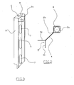
figure 1 shows a plan view, with the roofing removed, of a prefabricated unit according to the present invention; -
figure 2 shows an enlarged view of an angle, without any flange, of the unit offigure 1 ; -
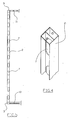
figure 3 shows a perspective view of a portion of the angle offigure 2 , with a flange; -
figure 4 shows a perspective view of a portion of a reinforcement post; -
figure 5 shows the V-V section offigure 1 . - Referring to the above-mentioned figures, a prefabricated building unit according to the present invention is globally indicated by 1.
- The
unit 1 comprises a rigid cage-like structure internally lined withpanels 100 and comprising a plurality ofposts 2, of equal height, fixed on the top and at the bottom tobeams 3, to which thefloor 10 and theceiling 11 are fixed, respectively (Fig. 5 ). - The structure presents a prismatic configuration with the perimeters of the opposed bases defined by the upper and
lower beams 3, respectively. - In particular, in the example, the structure is a parallelepiped with four squared- or rectangular-section posts, arranged at the angles, which for simplicity we will call
angular posts 2a and the rest of theposts 2, with an H-shaped section, placed equidistantly and having the function of reinforcement of the walls formed by thepanels 100. - According to an embodiment of the present invention, a
flat spacing element 4, to which anangular section bar 5 formed by twowings 51 placed at 90° is fixed, is fixed in a cantilevered manner to eachangular post 2a, for example by welding, from anedge 2b facing the inside of the structure. - The assembly formed by the
spacing element 4 and by the correspondingangular section bar 5 presents a fork or "Y" section configuration (Fig. 2 ). - In particular, the
spacing element 4 is placed with respect to theangular post 2a to which it is fixed, in such a way that the vertical plane lying on thespacing element 4 itself crosses theangular post 2a preferably passing through its diagonal, while thewings 51 are always parallel to the sides of thepost 2a. - Essentially, the
spacing elements 4 form four cantilevered ribs facing the central area of the structure and eachangular section bar 5 presents an "L" configuration with a 90° dihedral angle facing the inside of the structure. - Therefore, the overall structure of the example presents, at the four angles, the four
angular section bars 5 arranged to receive in abutment theinternal lining panels 100, whose assembly is shown infigure 1 , ensuring high assembly precision. - In order to ensure greater resistance and stability, a
reinforcement plate 6 is fixed to each angle near the upper end (Fig. 3 ), horizontally arranged, which holds together, according to a fixed arrangement, theangular post 2a, thespacing element 4 and theangular section bar 5. - According to the preferred embodiment and in order to optimise the overall dimensions, each
spacing element 4 arranged at the angles is provided with a plurality ofslots 7 to allow for the passage of various cables and/or pipes to be connected to the building's utilities where theunit 1 has to be inserted. Thisslot 7 arrangement allows for leaving theangular posts 2a untouched, further easing the passage of cables and pipes compared to the known art. - Of course, the
wall reinforcement posts 2, that is those that are not placed at the angles, are located with the support plane of thepanels 100, formed by one of the two parallel elements of the H-shaped section bar, coplanar with the arms of theangular section bar 5 and furthermore they are provided withcrossing slots 7 placed on the central transversal element of the H-shaped section bar. - In order to ease the lifting of the
unit 1, an internally threaded sleeve 8 (Fig. 2 ) to screw a hook, not shown, for the passage of support cables, is fixed to eachangular post 2a, near the upper end. When the positioning of the unit is completed, the hooks may be unscrewed, reestablishing the levelness of the upper surface. - The
posts beams 3 are made of metal, steel for example, according to the known art and subsequently undergo cold galvanising in order to improve their resistance to corrosion. - The panels are made of plaster fibre (Fermacell), in order to have greater mechanical strength and be mostly resistant to humidity compared to plasterboard panels.
- In alternative to the above-described embodiment, it is possible to fix the
angular section bar 5 directly onto theangular post 2a without the help of aspacing element 4. - As may be understood from what has been described, the prefabricated building unit according to the present invention allows for meeting the requirements and overcoming the drawbacks mentioned in the introduction of the present description with reference to the prior art.
- In fact, the prefabricated unit according to the present invention, thanks to the presence of L-shaped angular section bars fixed to the angular beams through the spacing elements, allows for the precise and fast assembly of the panels.
- Furthermore, the location of the slots on the spacing elements considerably facilitates the dislocation of the cables and pipes on the external side of the panels.
- Obviously, one skilled in the art may make numerous modifications and changes to the above-described prefabricated building unit, all of which fall under the protection scope of the invention as defined in the following claims, in order to meet specific and incidental requirements.
Claims (11)
- A prefabricated building unit (1) comprising a rigid structure formed by tubular posts (2, 2a) and beams (3) making a cage which is internally lined with panels (100), at least part of said posts (2a) being arranged at the angles of said structure, wherein an angular section bar (5) configured to define a dihedral angle facing the inside of the structure is associated with each tubular post (2a) arranged at the angle, characterised in that said angular section bars (5) are arranged inside the cage and receive in abutment the internal lining panels (100) in the respective dihedral angle facing the inside of the structure.
- A unit (1) according to claim 1, wherein said dihedral angle is equal to approximately 90°.
- A unit (1) according to claim 1, wherein said angular section bar (5) presents an L-shaped configuration if seen in section.
- A unit (1) according to claim 1, wherein said angular section bar (5) is fixed directly onto the corresponding post (2a) by welding.
- A unit (1) according to claim 1, wherein said angular section bar (5) is associated with the corresponding post through an interposed spacing element (4) ledged with respect to the post (2a).
- A unit (1) according to claim 5, wherein said spacing element (4) presents a flat configuration.
- A unit (1) according to claim 6, wherein the assembly of said angular section bar (5) and said spacing element (4) presents a fork configuration, if seen in section.
- A unit (1) according to claim 7, wherein the posts (2,2a), the spacing elements (4) and the angular section bars (5) have the same height.
- A unit (1) according to claim 8, wherein reinforcement plates (6) are fixed to the upper end of the spacing elements (4) of the posts (2a) placed at the angles and of the angular section bars (5).
- A unit (1) according to claim 5, wherein said spacing element (4) is provided with at least one cable passing slot (7).
- A unit (1) according to claim 1, wherein an internally threaded sleeve (8) to screw a hook for the lifting of the structure is fixed to each tubular angular post (2a) arranged at the angle, near the upper end.
Priority Applications (9)
| Application Number | Priority Date | Filing Date | Title |
|---|---|---|---|
| SI200631191T SI1908889T1 (en) | 2006-10-02 | 2006-10-02 | Prefabricated building unit |
| ES06425675T ES2371483T3 (en) | 2006-10-02 | 2006-10-02 | PREFABRICATED CONSTRUCTION UNIT. |
| RS20110440A RS51947B (en) | 2006-10-02 | 2006-10-02 | PREFABRICATED CONSTRUCTION ELEMENT |
| EP06425675A EP1908889B1 (en) | 2006-10-02 | 2006-10-02 | Prefabricated building unit |
| PL06425675T PL1908889T3 (en) | 2006-10-02 | 2006-10-02 | Prefabricated building unit |
| PT06425675T PT1908889E (en) | 2006-10-02 | 2006-10-02 | Prefabricated building unit |
| AT06425675T ATE523642T1 (en) | 2006-10-02 | 2006-10-02 | PREFABRICATED COMPONENT |
| DK06425675.3T DK1908889T3 (en) | 2006-10-02 | 2006-10-02 | Prefabricated construction unit |
| HR20110866T HRP20110866T1 (en) | 2006-10-02 | 2011-11-21 | Prefabricated building unit |
Applications Claiming Priority (1)
| Application Number | Priority Date | Filing Date | Title |
|---|---|---|---|
| EP06425675A EP1908889B1 (en) | 2006-10-02 | 2006-10-02 | Prefabricated building unit |
Publications (2)
| Publication Number | Publication Date |
|---|---|
| EP1908889A1 EP1908889A1 (en) | 2008-04-09 |
| EP1908889B1 true EP1908889B1 (en) | 2011-09-07 |
Family
ID=37762552
Family Applications (1)
| Application Number | Title | Priority Date | Filing Date |
|---|---|---|---|
| EP06425675A Active EP1908889B1 (en) | 2006-10-02 | 2006-10-02 | Prefabricated building unit |
Country Status (9)
| Country | Link |
|---|---|
| EP (1) | EP1908889B1 (en) |
| AT (1) | ATE523642T1 (en) |
| DK (1) | DK1908889T3 (en) |
| ES (1) | ES2371483T3 (en) |
| HR (1) | HRP20110866T1 (en) |
| PL (1) | PL1908889T3 (en) |
| PT (1) | PT1908889E (en) |
| RS (1) | RS51947B (en) |
| SI (1) | SI1908889T1 (en) |
Families Citing this family (1)
| Publication number | Priority date | Publication date | Assignee | Title |
|---|---|---|---|---|
| JP7730629B2 (en) * | 2020-09-28 | 2025-08-28 | 積水化学工業株式会社 | Building Unit |
Family Cites Families (4)
| Publication number | Priority date | Publication date | Assignee | Title |
|---|---|---|---|---|
| US2337885A (en) * | 1941-06-06 | 1943-12-28 | Bell Telephone Labor Inc | Telephone booth |
| US3196993A (en) * | 1962-11-20 | 1965-07-27 | William H Holloman | Releasable connector for connecting structural elements in buildings, furniture and other articles |
| DE1684544A1 (en) * | 1966-05-07 | 1971-04-08 | Agroman Constr | Prefabricated barracks or the like. |
| US4192113A (en) * | 1977-06-27 | 1980-03-11 | Armco Inc. | Corner assembly for wall panels |
-
2006
- 2006-10-02 SI SI200631191T patent/SI1908889T1/en unknown
- 2006-10-02 ES ES06425675T patent/ES2371483T3/en active Active
- 2006-10-02 AT AT06425675T patent/ATE523642T1/en active
- 2006-10-02 DK DK06425675.3T patent/DK1908889T3/en active
- 2006-10-02 PL PL06425675T patent/PL1908889T3/en unknown
- 2006-10-02 RS RS20110440A patent/RS51947B/en unknown
- 2006-10-02 PT PT06425675T patent/PT1908889E/en unknown
- 2006-10-02 EP EP06425675A patent/EP1908889B1/en active Active
-
2011
- 2011-11-21 HR HR20110866T patent/HRP20110866T1/en unknown
Also Published As
| Publication number | Publication date |
|---|---|
| ATE523642T1 (en) | 2011-09-15 |
| PL1908889T3 (en) | 2012-02-29 |
| RS51947B (en) | 2012-02-29 |
| DK1908889T3 (en) | 2011-12-12 |
| SI1908889T1 (en) | 2012-01-31 |
| EP1908889A1 (en) | 2008-04-09 |
| HRP20110866T1 (en) | 2011-12-31 |
| PT1908889E (en) | 2011-11-30 |
| ES2371483T3 (en) | 2012-01-03 |
Similar Documents
| Publication | Publication Date | Title |
|---|---|---|
| JP7048685B2 (en) | Pre-assembled wall panels for public installation | |
| US11186983B2 (en) | Prefabricated building module | |
| RU2628352C2 (en) | Prefabricated module for building | |
| WO2024160302A2 (en) | Prefabricated room module, steel-concrete building module composite structure and steel-concrete building | |
| CA3109393C (en) | Precast building construction system | |
| EP1417383A1 (en) | Modular buildings | |
| WO2008004896A2 (en) | Building system | |
| EP1971727B1 (en) | Construction of buildings | |
| SK161099A3 (en) | Building framework | |
| EP1908889B1 (en) | Prefabricated building unit | |
| KR101279139B1 (en) | a Connecting Device of Modular Unit Corridor | |
| KR102625888B1 (en) | Modular housing with foundation support structure | |
| AU2018264129B2 (en) | Prefabricated building module | |
| JPH08312169A (en) | Method of compounding unit construction of multiple dwelling house | |
| JPS6365785B2 (en) | ||
| CN215978628U (en) | Support whole bathroom that two layers were built | |
| KR102740074B1 (en) | A Construction method using PC modulars | |
| KR100694702B1 (en) | Modular Residential Floor Systems | |
| KR100829954B1 (en) | Modular residential utility system | |
| HK40103257A (en) | Prefabricated room module, steel-concrete building module combined structure and steel-concrete building | |
| JP7609400B2 (en) | Dry floor support beams and beam-to-floor structure | |
| KR200228583Y1 (en) | The fixation device for light-weight wall | |
| JP3352043B2 (en) | Floor structure | |
| KR20250157891A (en) | Factory-made Lightweight Toilet Module For Minimizing On-site Wall Finishing And Method Of Manufacturing The Same | |
| JP2000291149A (en) | Connected unit house made of steel-frame |
Legal Events
| Date | Code | Title | Description |
|---|---|---|---|
| PUAI | Public reference made under article 153(3) epc to a published international application that has entered the european phase |
Free format text: ORIGINAL CODE: 0009012 |
|
| AK | Designated contracting states |
Kind code of ref document: A1 Designated state(s): AT BE BG CH CY CZ DE DK EE ES FI FR GB GR HU IE IS IT LI LT LU LV MC NL PL PT RO SE SI SK TR |
|
| AX | Request for extension of the european patent |
Extension state: AL BA HR MK RS |
|
| 17P | Request for examination filed |
Effective date: 20080918 |
|
| AKX | Designation fees paid |
Designated state(s): AT BE BG CH CY CZ DE DK EE ES FI FR GB GR HU IE IS IT LI LT LU LV MC NL PL PT RO SE SI SK TR |
|
| AXX | Extension fees paid |
Extension state: AL Payment date: 20080918 Extension state: RS Payment date: 20080918 Extension state: BA Payment date: 20080918 Extension state: HR Payment date: 20080918 Extension state: MK Payment date: 20080918 |
|
| 17Q | First examination report despatched |
Effective date: 20101104 |
|
| GRAP | Despatch of communication of intention to grant a patent |
Free format text: ORIGINAL CODE: EPIDOSNIGR1 |
|
| GRAS | Grant fee paid |
Free format text: ORIGINAL CODE: EPIDOSNIGR3 |
|
| GRAA | (expected) grant |
Free format text: ORIGINAL CODE: 0009210 |
|
| REG | Reference to a national code |
Ref country code: GB Ref legal event code: FG4D |
|
| REG | Reference to a national code |
Ref country code: CH Ref legal event code: EP |
|
| REG | Reference to a national code |
Ref country code: IE Ref legal event code: FG4D |
|
| REG | Reference to a national code |
Ref country code: CH Ref legal event code: NV Representative=s name: ISLER & PEDRAZZINI AG |
|
| REG | Reference to a national code |
Ref country code: RO Ref legal event code: EPE |
|
| REG | Reference to a national code |
Ref country code: DE Ref legal event code: R096 Ref document number: 602006024172 Country of ref document: DE Effective date: 20111103 |
|
| REG | Reference to a national code |
Ref country code: HR Ref legal event code: TUEP Ref document number: P20110866 Country of ref document: HR |
|
| REG | Reference to a national code |
Ref country code: SE Ref legal event code: TRGR |
|
| REG | Reference to a national code |
Ref country code: PT Ref legal event code: SC4A Free format text: AVAILABILITY OF NATIONAL TRANSLATION Effective date: 20111114 |
|
| REG | Reference to a national code |
Ref country code: DK Ref legal event code: T3 |
|
| REG | Reference to a national code |
Ref country code: NL Ref legal event code: T3 |
|
| REG | Reference to a national code |
Ref country code: HR Ref legal event code: T1PR Ref document number: P20110866 Country of ref document: HR |
|
| REG | Reference to a national code |
Ref country code: ES Ref legal event code: FG2A Ref document number: 2371483 Country of ref document: ES Kind code of ref document: T3 Effective date: 20120103 |
|
| PG25 | Lapsed in a contracting state [announced via postgrant information from national office to epo] |
Ref country code: LT Free format text: LAPSE BECAUSE OF FAILURE TO SUBMIT A TRANSLATION OF THE DESCRIPTION OR TO PAY THE FEE WITHIN THE PRESCRIBED TIME-LIMIT Effective date: 20110907 |
|
| LTIE | Lt: invalidation of european patent or patent extension |
Effective date: 20110907 |
|
| PG25 | Lapsed in a contracting state [announced via postgrant information from national office to epo] |
Ref country code: LV Free format text: LAPSE BECAUSE OF FAILURE TO SUBMIT A TRANSLATION OF THE DESCRIPTION OR TO PAY THE FEE WITHIN THE PRESCRIBED TIME-LIMIT Effective date: 20110907 Ref country code: CY Free format text: LAPSE BECAUSE OF FAILURE TO SUBMIT A TRANSLATION OF THE DESCRIPTION OR TO PAY THE FEE WITHIN THE PRESCRIBED TIME-LIMIT Effective date: 20110907 Ref country code: GR Free format text: LAPSE BECAUSE OF FAILURE TO SUBMIT A TRANSLATION OF THE DESCRIPTION OR TO PAY THE FEE WITHIN THE PRESCRIBED TIME-LIMIT Effective date: 20111208 |
|
| REG | Reference to a national code |
Ref country code: PL Ref legal event code: T3 |
|
| PG25 | Lapsed in a contracting state [announced via postgrant information from national office to epo] |
Ref country code: IS Free format text: LAPSE BECAUSE OF FAILURE TO SUBMIT A TRANSLATION OF THE DESCRIPTION OR TO PAY THE FEE WITHIN THE PRESCRIBED TIME-LIMIT Effective date: 20120107 Ref country code: SK Free format text: LAPSE BECAUSE OF FAILURE TO SUBMIT A TRANSLATION OF THE DESCRIPTION OR TO PAY THE FEE WITHIN THE PRESCRIBED TIME-LIMIT Effective date: 20110907 Ref country code: CZ Free format text: LAPSE BECAUSE OF FAILURE TO SUBMIT A TRANSLATION OF THE DESCRIPTION OR TO PAY THE FEE WITHIN THE PRESCRIBED TIME-LIMIT Effective date: 20110907 |
|
| PG25 | Lapsed in a contracting state [announced via postgrant information from national office to epo] |
Ref country code: EE Free format text: LAPSE BECAUSE OF FAILURE TO SUBMIT A TRANSLATION OF THE DESCRIPTION OR TO PAY THE FEE WITHIN THE PRESCRIBED TIME-LIMIT Effective date: 20110907 |
|
| PLBE | No opposition filed within time limit |
Free format text: ORIGINAL CODE: 0009261 |
|
| STAA | Information on the status of an ep patent application or granted ep patent |
Free format text: STATUS: NO OPPOSITION FILED WITHIN TIME LIMIT |
|
| 26N | No opposition filed |
Effective date: 20120611 |
|
| REG | Reference to a national code |
Ref country code: DE Ref legal event code: R097 Ref document number: 602006024172 Country of ref document: DE Effective date: 20120611 |
|
| PG25 | Lapsed in a contracting state [announced via postgrant information from national office to epo] |
Ref country code: BG Free format text: LAPSE BECAUSE OF FAILURE TO SUBMIT A TRANSLATION OF THE DESCRIPTION OR TO PAY THE FEE WITHIN THE PRESCRIBED TIME-LIMIT Effective date: 20111207 |
|
| PG25 | Lapsed in a contracting state [announced via postgrant information from national office to epo] |
Ref country code: TR Free format text: LAPSE BECAUSE OF FAILURE TO SUBMIT A TRANSLATION OF THE DESCRIPTION OR TO PAY THE FEE WITHIN THE PRESCRIBED TIME-LIMIT Effective date: 20110907 |
|
| PG25 | Lapsed in a contracting state [announced via postgrant information from national office to epo] |
Ref country code: HU Free format text: LAPSE BECAUSE OF FAILURE TO SUBMIT A TRANSLATION OF THE DESCRIPTION OR TO PAY THE FEE WITHIN THE PRESCRIBED TIME-LIMIT Effective date: 20110907 |
|
| REG | Reference to a national code |
Ref country code: FR Ref legal event code: PLFP Year of fee payment: 10 |
|
| REG | Reference to a national code |
Ref country code: FR Ref legal event code: PLFP Year of fee payment: 11 |
|
| REG | Reference to a national code |
Ref country code: FR Ref legal event code: PLFP Year of fee payment: 12 |
|
| REG | Reference to a national code |
Ref country code: FR Ref legal event code: PLFP Year of fee payment: 13 |
|
| REG | Reference to a national code |
Ref country code: HR Ref legal event code: ODRP Ref document number: P20110866 Country of ref document: HR Payment date: 20190920 Year of fee payment: 14 |
|
| REG | Reference to a national code |
Ref country code: HR Ref legal event code: ODRP Ref document number: P20110866 Country of ref document: HR Payment date: 20200923 Year of fee payment: 15 |
|
| REG | Reference to a national code |
Ref country code: HR Ref legal event code: ODRP Ref document number: P20110866 Country of ref document: HR Payment date: 20210921 Year of fee payment: 16 |
|
| REG | Reference to a national code |
Ref country code: HR Ref legal event code: ODRP Ref document number: P20110866 Country of ref document: HR Payment date: 20220921 Year of fee payment: 17 |
|
| REG | Reference to a national code |
Ref country code: HR Ref legal event code: ODRP Ref document number: P20110866 Country of ref document: HR Payment date: 20230919 Year of fee payment: 18 |
|
| REG | Reference to a national code |
Ref country code: HR Ref legal event code: ODRP Ref document number: P20110866 Country of ref document: HR Payment date: 20240918 Year of fee payment: 19 |
|
| PGFP | Annual fee paid to national office [announced via postgrant information from national office to epo] |
Ref country code: PT Payment date: 20250918 Year of fee payment: 20 |
|
| REG | Reference to a national code |
Ref country code: HR Ref legal event code: ODRP Ref document number: P20110866 Country of ref document: HR Payment date: 20250929 Year of fee payment: 20 |
|
| PGFP | Annual fee paid to national office [announced via postgrant information from national office to epo] |
Ref country code: MC Payment date: 20250925 Year of fee payment: 20 |
|
| PGFP | Annual fee paid to national office [announced via postgrant information from national office to epo] |
Ref country code: PL Payment date: 20250926 Year of fee payment: 20 Ref country code: IT Payment date: 20250725 Year of fee payment: 20 |
|
| PGFP | Annual fee paid to national office [announced via postgrant information from national office to epo] |
Ref country code: RO Payment date: 20250925 Year of fee payment: 20 |
|
| PGFP | Annual fee paid to national office [announced via postgrant information from national office to epo] |
Ref country code: SI Payment date: 20250917 Year of fee payment: 20 |
|
| REG | Reference to a national code |
Ref country code: CH Ref legal event code: U11 Free format text: ST27 STATUS EVENT CODE: U-0-0-U10-U11 (AS PROVIDED BY THE NATIONAL OFFICE) Effective date: 20251101 |
|
| PGFP | Annual fee paid to national office [announced via postgrant information from national office to epo] |
Ref country code: NL Payment date: 20251026 Year of fee payment: 20 Ref country code: LU Payment date: 20251027 Year of fee payment: 20 |
|
| PGFP | Annual fee paid to national office [announced via postgrant information from national office to epo] |
Ref country code: DE Payment date: 20251029 Year of fee payment: 20 |
|
| PGFP | Annual fee paid to national office [announced via postgrant information from national office to epo] |
Ref country code: GB Payment date: 20251027 Year of fee payment: 20 |
|
| PGFP | Annual fee paid to national office [announced via postgrant information from national office to epo] |
Ref country code: AT Payment date: 20251029 Year of fee payment: 20 |
|
| PGFP | Annual fee paid to national office [announced via postgrant information from national office to epo] |
Ref country code: FI Payment date: 20251027 Year of fee payment: 20 Ref country code: DK Payment date: 20251027 Year of fee payment: 20 |
|
| PGFP | Annual fee paid to national office [announced via postgrant information from national office to epo] |
Ref country code: FR Payment date: 20251027 Year of fee payment: 20 |
|
| PGFP | Annual fee paid to national office [announced via postgrant information from national office to epo] |
Ref country code: BE Payment date: 20251027 Year of fee payment: 20 |
|
| PGFP | Annual fee paid to national office [announced via postgrant information from national office to epo] |
Ref country code: SE Payment date: 20251027 Year of fee payment: 20 Ref country code: CH Payment date: 20251101 Year of fee payment: 20 |
|
| PGFP | Annual fee paid to national office [announced via postgrant information from national office to epo] |
Ref country code: IE Payment date: 20251027 Year of fee payment: 20 |
|
| PGFP | Annual fee paid to national office [announced via postgrant information from national office to epo] |
Ref country code: ES Payment date: 20251103 Year of fee payment: 20 |