EP1908715B1 - Method for inserting marking inserts - Google Patents
Method for inserting marking inserts Download PDFInfo
- Publication number
- EP1908715B1 EP1908715B1 EP07117108.6A EP07117108A EP1908715B1 EP 1908715 B1 EP1908715 B1 EP 1908715B1 EP 07117108 A EP07117108 A EP 07117108A EP 1908715 B1 EP1908715 B1 EP 1908715B1
- Authority
- EP
- European Patent Office
- Prior art keywords
- inserts
- document
- marking
- stack
- sheets
- Prior art date
- Legal status (The legal status is an assumption and is not a legal conclusion. Google has not performed a legal analysis and makes no representation as to the accuracy of the status listed.)
- Not-in-force
Links
Images


Classifications
-
- B—PERFORMING OPERATIONS; TRANSPORTING
- B65—CONVEYING; PACKING; STORING; HANDLING THIN OR FILAMENTARY MATERIAL
- B65H—HANDLING THIN OR FILAMENTARY MATERIAL, e.g. SHEETS, WEBS, CABLES
- B65H33/00—Forming counted batches in delivery pile or stream of articles
- B65H33/04—Forming counted batches in delivery pile or stream of articles by inserting marker slips in pile or stream
-
- G—PHYSICS
- G03—PHOTOGRAPHY; CINEMATOGRAPHY; ANALOGOUS TECHNIQUES USING WAVES OTHER THAN OPTICAL WAVES; ELECTROGRAPHY; HOLOGRAPHY
- G03G—ELECTROGRAPHY; ELECTROPHOTOGRAPHY; MAGNETOGRAPHY
- G03G15/00—Apparatus for electrographic processes using a charge pattern
- G03G15/65—Apparatus which relate to the handling of copy material
- G03G15/6538—Devices for collating sheet copy material, e.g. sorters, control, copies in staples form
- G03G15/655—Placing job divider sheet between set of sheets
Definitions
- the invention relates to a method of inserting a plurality of inserts from a distinguishable set into a multi-sheet document, comprising the steps of inserting inserts into the document in accordance with a job definition, such that a stack of inserts and processed sheets is obtained, said stack having at least one aligned side and determining the number of surplus inserts.
- a method for inserting marking inserts is provided wherein the surplus of inserts is inserted at the end of the document offset the aligned side of said stack.
- the multi-sheet document may comprise processed and unprocessed sheets.
- the sheets may for example be paper sheets, such as. A4 plain paper sheets, glossy media or the like, or transparent overhead sheets, or other synthetic sheets.
- a distinguishable set of inserts is a set of inserts that is distinguishable as a set. In general such a set has a predetermined number of members. These members may for example have a certain sequence of colours, such that the set is distinguishable as a set.
- Another example of a distinguishable set of inserts is a set of tab-sheets. Such a set typically has a number of tab-sheets per set, all having a tabbed part which is offsetted with respect to the previous tab-sheet in the set. Such a set is distinguishable as a set of inserts. Other cyclic media may also form a distinguishable set of inserts. Inserting marking inserts may be executed inline, i.e.
- An offline document finisher may comprise an input tray for inputting processed sheets of a multi-sheet document and a separate input tray for inputting marking inserts and outputs a stack of documents.
- the surplus of inserts may be processed with the method according to the invention, such that the sheet processing apparatus can restart the aborted job, or continue with the next job with a new set of inserts, while the surplus of inserts which are place offset the aligned stack functions as a identifier for the aborted job.
- the inserts are marking inserts having an extending portion, the method being such that the extending portion extends out of the stack when aligned at the side opposite to the extending portion.
- the extending portions contribute to an easier handling of the document as the marking inserts mark the set division inside the document.
- the side opposite to the extending portion of the surplus of marking inserts each having a positive offset with respect to the aligned side of the stack in the direction that extends from the aligned side of the stack towards the extending portion of the marking inserts.
- the resulting document division is clearly distinguishable from the set division and easily extractable by the operator.
- the positive offset of the surplus of marking inserts may be different for each individual marking insert of the surplus of marking inserts.
- Figure 1 shows a system of workstations (WS) and at least one printer (PR) connected by a network (N).
- Workstations for example, are PC's and are in each case equipped with a processor unit, a monitor, a keyboard and a mouse or other indicator instrument.
- the term "printer” includes a digital copying machine in this context.
- a digital copying machine comprises a scanner, a printer, a user interface and a connection unit for connecting to the network and processing print jobs sent from the workstations. Users who wish to have a specific data file printed from their workstation may select one specific or all printers in the system.
- Figure 2 shows a digital copying machine 1 suitable for use in the system as shown in Figure 1 . The various parts being shown diagrammatically separately.
- These parts comprise a document feeder 110 for physically handling the documents for copying, a scanner unit 112 for generating digital image data corresponding to an image appearing on a document, a printer unit 130 for making prints of images on print media in accordance with digital data, a multi-tray media supply unit 140 for supplying media to the printer unit 130 and a finishing and outputting section 150, a user-interface unit 160, a control unit 170 and a network communication unit 171.
- the document feeder 110 is provided with an input tray 111 for inputting a stack of sheets of a document, a transport mechanism (not shown) for transporting the sheets one by one along the scanner unit 120 and an output tray 112 in which the sheets are placed after scanning.
- the scanner unit 120 comprises a flat bed scanner provided with a glass plate on which an original document can be placed, an optical image CCD sensor array and an imaging unit comprising a movable mirror and lens system for imaging the document on the CCD sensor array.
- the CCD sensor array generates a series of electrical signals which are converted to digital image data in manner known per se.
- the printer unit 130 comprises an electro-photographic processing stage known per se, in which a photo-conductive medium 131 in the form of a band is charged by means of a corona unit 132 and then selectively discharged by exposing to a LED array 133 in accordance with digital image data.
- the charge image thus formed on the medium 131 is developed with toner powder in a developing unit 134, whereafter the toner image is transferred, in a combined transfer and fixing unit 135, to a heated rubber belt 136 on which the toner powder softens as a result of the heat of the belt 136 and becomes tacky. It is then transferred and fixed on a print media, usually a sheet of paper, fed from a media supply unit 140 via a conveyor 137.
- a supply of print media (for example sheets of paper) in different formats and orientations is available in the media supply unit.
- the print media with the toner image is transported via a conveyor 138 to the finishing and outputting section 150, which if necessary collects them into sets and then deposits them in the output tray 151.
- the outputting section 150 may comprise a high capacity stacking unit (not shown) for stacking many documents at a time.
- the user interface panel of the unit 160 is provided with a display screen and keys.
- Unit 160 is connected to the control unit 170 and the network communication unit 171.
- the control unit of printer 1 is shown diagrammatically by reference 170. It comprises modules for controlling the units 110, 120, 130, 140, 150 and 160 and an image processing module for processing the digital image data so that prints of good image quality can be made by printer unit 130.
- the control unit 170 having a controller arrangement that is devised in order to have the system 1 to operate and to perform the method according to the present invention.
- the apparatus also includes a network communication unit 171 for communicating over a local network N, which is diagrammatically shown as cable 172.
- the network communication unit 171 receives print jobs from the workstations, converts them to a format that can be processed by the printer unit 130 and in co-operation with the control unit 170 prints the associated images on a print media.
- a program for sending print jobs to the printer is operative in the workstations WS.
- a program of this kind is termed a "printer driver" and is logically coupled via the network N to one or more printers.
- the printer driver displays a job window on the workstation monitor, in which the user can input specifications for the intended print job, such as the choice of print media, double or single sides printing and several finishing options.
- Documents may come in a large variety in sizes, forms and finishing. Depending on the intended use, a document may comprise marking inserts such as, for example tab-sheets. Tab-sheets mark the position of a part of the document. The divided parts of a document are called sets.
- Figure 3 is a diagram of a set 3 of a document.
- the diagrammatically illustrated set 2 comprises five sheets of print media 4 which are covered by a tab-sheet 3. This tab-sheet 3 has an extending portion for easy marking of and browsing to the position of the set 2.
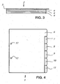
- FIG. 4 is an illustration of a set of tab-sheets 5.
- a set of this kind is commonly used for marking sets of printed media in a document. Usually such sets of marking inserts are supplied in fixed sizes.
- the illustrated set of tab-sheets 5 comprise six tab-sheets 6, 7, 8, 9, 10, 11.
- the extending portion of tab-sheet 7 is placed at an offset with respect to the extending portion of tab-sheet 6, the extending portion of tab-sheet 8 is placed at an offset with respect to the extending portion of tab-sheet 7, and so on.
- the offsetting of the extending portions of the tab-sheets is chosen for easy indexing of the individual tab-sheets 6, 7, 8, 9, 10, 11 and the associated sets of printed media.
- the tab-sheets 6, 7, 8, 9, 10, 11 are pre-perforated with perforations 12 for easy handling.
- tab-sheets may be supplied in all kinds of forms and features.
- tab-sheets have at least one side for aligning with the stacked set of printed media and one side, usually opposite to the aligning side with an extending portion, for easy identifying the tab-sheet and associated set of printed media.
- FIG. 5A is a schematic side view and Figure 5B is a schematic top view of a print job, processed according to an embodiment of the method according to the invention.
- An exemplary print job 20 comprises two documents, document 25 and document 26.
- This print job 20 is prepared to be executed on a printing system, comprising a controller arrangement that is devised in order to have the printing system perform a method according to the present invention.
- a controller arrangement can be a single piece of hardware, such as an ASIC, but can also be devised as an arrangement being distributed over several components or even separate hardware devices, optionally partly or substantially completely constituted in software.
- the actual constitution of the controller arrangement is not essential for enabling the application of the present invention.
- a user Before sending the print job to the printing system, a user can program the requirements for the print job in the printer driver window on a workstation. In this printer driver the user can set the option for inserting marking inserts to "ON". The user may now enter the number of marking inserts in the available set. In the example on hand, the user enters that the set of marking inserts comprises six inserts. By defining the position of the marking inserts, document 25 is divided into sets 30. In this case, four sets 30 all provided with one of the set of six marking inserts available in each set of marking inserts. These options and settings may also be entered on a local user interface, such as the graphical user interface The controller now determines the number of surplus marking inserts and starts operation. The sheets of print media 4 are printed in the print unit of the printing system.
- the marking inserts are fed to the output tray such that the marking inserts are correctly placed at the end of each set 30 in the document 25.
- the marking inserts may be supplied in plural in a separate input tray of the media supply unit 140.
- the document 25 comprising the printed media 4 and the marking inserts 6, 7, 8, 9, 10 and 11 are aligned.
- the controlling assembly controls the conveyance of the surplus of marking inserts to the output tray.
- the number of marking inserts in each distinguishable set may be counted automatically upon inserting the sets. In that case a user does not have to enter the number of marking inserts manually.
- the amount of offset may be set in the controller or in the printer driver. If a user intends to extract the surplus of marking inserts manually he may require a larger offset than in the case of a user who uses the offset of the surplus of marking inserts merely as a document divider and keeps the complete set, including the surplus of marking inserts together.
- the set of marking inserts may be inserted into the document directly from the marking inserts storage, or the marking inserts may enter into the printing unit.
- the latter enables the marking inserts to be provided with a printed image, such as chapter name and number or a coloured coding to distinguish between the sets in the document.
Description
- The invention relates to a method of inserting a plurality of inserts from a distinguishable set into a multi-sheet document, comprising the steps of inserting inserts into the document in accordance with a job definition, such that a stack of inserts and processed sheets is obtained, said stack having at least one aligned side and determining the number of surplus inserts.
- A method of this kind is described in
US 5044619 . The method inserts sets of covers and tab-sheets into the correct position of the documents and determines whether the number of inserts per set is larger than the required number of inserts. If so, the surplus of inserts is then purged to another tray different from the tray on which the document is outputted.
However, it is a disadvantage of this known method, that the sets of inserts are broken up, and an additional tray and associated conveying means are needed to output the surplus of inserts and in general no distinct document dividing indication is available to indicate the start and ending of the documents on the stack. - It is an object of the invention to maintain the neatness of the complete sets of marking inserts while providing an indication of the documents division. To this end a method for inserting marking inserts is provided wherein the surplus of inserts is inserted at the end of the document offset the aligned side of said stack. By inserting the surplus at the end of the document offset the aligned side of the stack the operator is provided with a document division indication and can choose to extract the surplus out of the document or to keep the document, including the surplus of inserts together.
- One could also insert the surplus of inserts at the end of the document, whereby all inserts are aligned with the rest of the document, including the surplus of inserts. It is a disadvantage of that case that the extraction of the surplus out of the stack easily results in a disalignment of the stack.
- The multi-sheet document may comprise processed and unprocessed sheets. The sheets may for example be paper sheets, such as. A4 plain paper sheets, glossy media or the like, or transparent overhead sheets, or other synthetic sheets.
- A distinguishable set of inserts is a set of inserts that is distinguishable as a set. In general such a set has a predetermined number of members. These members may for example have a certain sequence of colours, such that the set is distinguishable as a set. Another example of a distinguishable set of inserts is a set of tab-sheets. Such a set typically has a number of tab-sheets per set, all having a tabbed part which is offsetted with respect to the previous tab-sheet in the set. Such a set is distinguishable as a set of inserts. Other cyclic media may also form a distinguishable set of inserts.
Inserting marking inserts may be executed inline, i.e. in the same apparatus where sheets are printed or offline, in a different apparatus, for example an offline document finisher. An offline document finisher may comprise an input tray for inputting processed sheets of a multi-sheet document and a separate input tray for inputting marking inserts and outputs a stack of documents. - In the case of an error in which the sheet processing apparatus can not finish an active job wherein a set of inserts is partly used at the occurrence of the error, the surplus of inserts may be processed with the method according to the invention, such that the sheet processing apparatus can restart the aborted job, or continue with the next job with a new set of inserts, while the surplus of inserts which are place offset the aligned stack functions as a identifier for the aborted job.
- In another embodiment of the method according to the invention the inserts are marking inserts having an extending portion, the method being such that the extending portion extends out of the stack when aligned at the side opposite to the extending portion.
The extending portions contribute to an easier handling of the document as the marking inserts mark the set division inside the document. - In a further embodiment of the method according to the invention, the side opposite to the extending portion of the surplus of marking inserts each having a positive offset with respect to the aligned side of the stack in the direction that extends from the aligned side of the stack towards the extending portion of the marking inserts.
The resulting document division is clearly distinguishable from the set division and easily extractable by the operator. The positive offset of the surplus of marking inserts may be different for each individual marking insert of the surplus of marking inserts. - The invention will now be explained in detail with reference to the accompanying drawings, wherein:
-
Figure 1 is a diagram of an example of a network system with workstations and a printer; -
Figure 2 is a diagram of an example of a printer for use according to the invention; -
Figure 3 is a diagram of a set of a document; -
Figure 4 is an illustration of a set of tab sheets; -
Figure 5A is a schematic side view of a print job, processed according to an embodiment of the method according to the invention; -
Figure 5B is a schematic top view of a print job, processed according to an embodiment of the method according to the invention; -
Figure 1 shows a system of workstations (WS) and at least one printer (PR) connected by a network (N). Workstations, for example, are PC's and are in each case equipped with a processor unit, a monitor, a keyboard and a mouse or other indicator instrument. The term "printer" includes a digital copying machine in this context. A digital copying machine comprises a scanner, a printer, a user interface and a connection unit for connecting to the network and processing print jobs sent from the workstations. Users who wish to have a specific data file printed from their workstation may select one specific or all printers in the system.
As an example,Figure 2 shows adigital copying machine 1 suitable for use in the system as shown inFigure 1 . The various parts being shown diagrammatically separately. These parts comprise adocument feeder 110 for physically handling the documents for copying, ascanner unit 112 for generating digital image data corresponding to an image appearing on a document, aprinter unit 130 for making prints of images on print media in accordance with digital data, a multi-traymedia supply unit 140 for supplying media to theprinter unit 130 and a finishing andoutputting section 150, a user-interface unit 160, acontrol unit 170 and anetwork communication unit 171. - The
document feeder 110 is provided with aninput tray 111 for inputting a stack of sheets of a document, a transport mechanism (not shown) for transporting the sheets one by one along thescanner unit 120 and anoutput tray 112 in which the sheets are placed after scanning. - The
scanner unit 120 comprises a flat bed scanner provided with a glass plate on which an original document can be placed, an optical image CCD sensor array and an imaging unit comprising a movable mirror and lens system for imaging the document on the CCD sensor array. During a scanning operation the CCD sensor array generates a series of electrical signals which are converted to digital image data in manner known per se.
Theprinter unit 130 comprises an electro-photographic processing stage known per se, in which a photo-conductive medium 131 in the form of a band is charged by means of acorona unit 132 and then selectively discharged by exposing to aLED array 133 in accordance with digital image data. The charge image thus formed on themedium 131 is developed with toner powder in a developingunit 134, whereafter the toner image is transferred, in a combined transfer andfixing unit 135, to aheated rubber belt 136 on which the toner powder softens as a result of the heat of thebelt 136 and becomes tacky. It is then transferred and fixed on a print media, usually a sheet of paper, fed from amedia supply unit 140 via aconveyor 137.
A supply of print media (for example sheets of paper) in different formats and orientations is available in the media supply unit.
The print media with the toner image is transported via aconveyor 138 to the finishing and outputtingsection 150, which if necessary collects them into sets and then deposits them in theoutput tray 151. Depending on the productivity and application of thedigital copying machine 1 theoutputting section 150 may comprise a high capacity stacking unit (not shown) for stacking many documents at a time.
The user interface panel of the unit 160 is provided with a display screen and keys. Unit 160 is connected to thecontrol unit 170 and thenetwork communication unit 171. The control unit ofprinter 1 is shown diagrammatically byreference 170. It comprises modules for controlling theunits printer unit 130. Thecontrol unit 170 having a controller arrangement that is devised in order to have thesystem 1 to operate and to perform the method according to the present invention.
As already stated, the apparatus also includes anetwork communication unit 171 for communicating over a local network N, which is diagrammatically shown ascable 172. Thenetwork communication unit 171 receives print jobs from the workstations, converts them to a format that can be processed by theprinter unit 130 and in co-operation with thecontrol unit 170 prints the associated images on a print media. - A program for sending print jobs to the printer is operative in the workstations WS. A program of this kind is termed a "printer driver" and is logically coupled via the network N to one or more printers. When a user wants to send a print job, he executes the printer driver. In response, the printer driver displays a job window on the workstation monitor, in which the user can input specifications for the intended print job, such as the choice of print media, double or single sides printing and several finishing options.
- Documents may come in a large variety in sizes, forms and finishing. Depending on the intended use, a document may comprise marking inserts such as, for example tab-sheets. Tab-sheets mark the position of a part of the document. The divided parts of a document are called sets.
Figure 3 is a diagram of aset 3 of a document. The diagrammatically illustrated set 2 comprises five sheets ofprint media 4 which are covered by a tab-sheet 3. This tab-sheet 3 has an extending portion for easy marking of and browsing to the position of theset 2. -
Figure 4 is an illustration of a set of tab-sheets 5. A set of this kind is commonly used for marking sets of printed media in a document. Usually such sets of marking inserts are supplied in fixed sizes. The illustrated set of tab-sheets 5 comprise six tab-sheets sheet 7 is placed at an offset with respect to the extending portion of tab-sheet 6, the extending portion of tab-sheet 8 is placed at an offset with respect to the extending portion of tab-sheet 7, and so on. The offsetting of the extending portions of the tab-sheets is chosen for easy indexing of the individual tab-sheets
The tab-sheets perforations 12 for easy handling. It will be clear for the skilled person that tab-sheets may be supplied in all kinds of forms and features. Usually tab-sheets have at least one side for aligning with the stacked set of printed media and one side, usually opposite to the aligning side with an extending portion, for easy identifying the tab-sheet and associated set of printed media. -
Figure 5A is a schematic side view andFigure 5B is a schematic top view of a print job, processed according to an embodiment of the method according to the invention. Anexemplary print job 20 comprises two documents,document 25 anddocument 26. Thisprint job 20 is prepared to be executed on a printing system, comprising a controller arrangement that is devised in order to have the printing system perform a method according to the present invention. Such a controller arrangement can be a single piece of hardware, such as an ASIC, but can also be devised as an arrangement being distributed over several components or even separate hardware devices, optionally partly or substantially completely constituted in software. For the skilled man it will be clear that the actual constitution of the controller arrangement is not essential for enabling the application of the present invention.
Before sending the print job to the printing system, a user can program the requirements for the print job in the printer driver window on a workstation. In this printer driver the user can set the option for inserting marking inserts to "ON". The user may now enter the number of marking inserts in the available set. In the example on hand, the user enters that the set of marking inserts comprises six inserts. By defining the position of the marking inserts,document 25 is divided into sets 30. In this case, four sets 30 all provided with one of the set of six marking inserts available in each set of marking inserts. These options and settings may also be entered on a local user interface, such as the graphical user interface
The controller now determines the number of surplus marking inserts and starts operation. The sheets ofprint media 4 are printed in the print unit of the printing system. In a timed fashion the marking inserts are fed to the output tray such that the marking inserts are correctly placed at the end of each set 30 in thedocument 25. The marking inserts may be supplied in plural in a separate input tray of themedia supply unit 140. At the output tray thedocument 25 comprising the printedmedia 4 and the marking inserts 6, 7, 8, 9, 10 and 11 are aligned. After conveying the last sheet of printed media to the output tray the controlling assembly controls the conveyance of the surplus of marking inserts to the output tray. These surplus of marking inserts are inserted offset the aligned side of the stack such that the surplus of marking inserts extend out of the stack, such that these surplus marking inserts are recognisable over the marking inserts that indicate the set dividing of the document. This procedure is repeated fordocument 26 - The number of marking inserts in each distinguishable set may be counted automatically upon inserting the sets. In that case a user does not have to enter the number of marking inserts manually.
- The amount of offset may be set in the controller or in the printer driver. If a user intends to extract the surplus of marking inserts manually he may require a larger offset than in the case of a user who uses the offset of the surplus of marking inserts merely as a document divider and keeps the complete set, including the surplus of marking inserts together.
- The set of marking inserts may be inserted into the document directly from the marking inserts storage, or the marking inserts may enter into the printing unit. The latter enables the marking inserts to be provided with a printed image, such as chapter name and number or a coloured coding to distinguish between the sets in the document.
Claims (5)
- A method of inserting a plurality of inserts (6-11) from a distinguishable set into a multi-sheet document (25, 26), comprising the steps of:- inserting inserts into the document in accordance with a job definition, such that a stack of inserts and processed sheets is obtained, said stack having at least one aligned side; and- determining the number of surplus inserts (10, 11);characterised in that the surplus (10, 11) of inserts is inserted at the end of the document offset (40) the aligned side of said stack.
- A method according to claim 1, wherein the inserts (6-11) are marking inserts having an extending portion, the method being such that the extending portion extends out of the stack when aligned at the side opposite to the extending portion.
- A method according to claim 2, wherein the side opposite to the extending portion of the surplus (10, 11) of marking inserts each having a positive offset with respect to the aligned side of the stack in the direction that extends from the aligned side of the stack towards the extending portion of the marking inserts.
- A method according to any one of preceding claims, wherein the inserts (6-11) are tab-sheets.
- A sheet processing apparatus (1), comprising a controller arrangement configured for executing the method according to any one of claims 1 to 4.
Priority Applications (1)
| Application Number | Priority Date | Filing Date | Title |
|---|---|---|---|
| EP07117108.6A EP1908715B1 (en) | 2006-10-05 | 2007-09-25 | Method for inserting marking inserts |
Applications Claiming Priority (2)
| Application Number | Priority Date | Filing Date | Title |
|---|---|---|---|
| EP06121803 | 2006-10-05 | ||
| EP07117108.6A EP1908715B1 (en) | 2006-10-05 | 2007-09-25 | Method for inserting marking inserts |
Publications (2)
| Publication Number | Publication Date |
|---|---|
| EP1908715A1 EP1908715A1 (en) | 2008-04-09 |
| EP1908715B1 true EP1908715B1 (en) | 2014-09-17 |
Family
ID=39148390
Family Applications (1)
| Application Number | Title | Priority Date | Filing Date |
|---|---|---|---|
| EP07117108.6A Not-in-force EP1908715B1 (en) | 2006-10-05 | 2007-09-25 | Method for inserting marking inserts |
Country Status (1)
| Country | Link |
|---|---|
| EP (1) | EP1908715B1 (en) |
Family Cites Families (2)
| Publication number | Priority date | Publication date | Assignee | Title |
|---|---|---|---|---|
| US5044619A (en) * | 1990-05-14 | 1991-09-03 | Xerox Corporation | Control of pre-ordered stock |
| US6227531B1 (en) * | 1999-05-25 | 2001-05-08 | Hewlett-Packard Company | Job separation process, system and method for distributing print jobs |
-
2007
- 2007-09-25 EP EP07117108.6A patent/EP1908715B1/en not_active Not-in-force
Also Published As
| Publication number | Publication date |
|---|---|
| EP1908715A1 (en) | 2008-04-09 |
Similar Documents
| Publication | Publication Date | Title |
|---|---|---|
| EP1120274B1 (en) | Inserting test patterns in large print jobs | |
| US7426352B2 (en) | Image formation apparatus | |
| US8777207B2 (en) | Printing apparatus, control method thereof and storage medium storing program | |
| US10362185B2 (en) | Image forming apparatus, image forming system, and control program for image forming system | |
| EP3358422B1 (en) | Method, image forming apparatus and non-transitory computer-readable recording medium for arranging marks at scheduled cutting positions | |
| JP2010102398A (en) | Printer driver program, printing controller and printing system | |
| CN103847254A (en) | Printing system, printing apparatus and method of controlling the same | |
| US20080107515A1 (en) | Method for inserting making inserts | |
| US20070017397A1 (en) | Image printing system, image printing method, and image printing program | |
| JP2013111871A (en) | Inspection system, control method of inspection system, and program | |
| US8170464B2 (en) | Image forming apparatus capable of preventing mismatching of punched hole position and binding direction | |
| EP2236447B1 (en) | Space Efficient Multi-Sheet Buffer Module and Modular Printing System | |
| US20130215437A1 (en) | Printing apparatus, control method therefor and storage medium | |
| US9026030B2 (en) | Multi-job feeder system | |
| EP1908715B1 (en) | Method for inserting marking inserts | |
| US8169662B2 (en) | System and method for reducing print delays for print jobs | |
| EP1148705A1 (en) | Determination of the image orientation in a digital copying apparatus | |
| JP2008173937A (en) | Image forming device | |
| JP2016149600A (en) | Image forming apparatus | |
| EP2431314B1 (en) | Image forming apparatus and control method thereof | |
| US8200142B2 (en) | Multi-job feeder apparatus and method | |
| JP2004229236A (en) | Image forming apparatus and image forming method | |
| US20100067966A1 (en) | Reconfigurable sheet transport module | |
| JP2007008099A (en) | Image forming system | |
| JP2006031479A (en) | Image forming apparatus |
Legal Events
| Date | Code | Title | Description |
|---|---|---|---|
| PUAI | Public reference made under article 153(3) epc to a published international application that has entered the european phase |
Free format text: ORIGINAL CODE: 0009012 |
|
| AK | Designated contracting states |
Kind code of ref document: A1 Designated state(s): AT BE BG CH CY CZ DE DK EE ES FI FR GB GR HU IE IS IT LI LT LU LV MC MT NL PL PT RO SE SI SK TR |
|
| AX | Request for extension of the european patent |
Extension state: AL BA HR MK RS |
|
| 17P | Request for examination filed |
Effective date: 20081009 |
|
| AKX | Designation fees paid |
Designated state(s): AT BE BG CH CY CZ DE DK EE ES FI FR GB GR HU IE IS IT LI LT LU LV MC MT NL PL PT RO SE SI SK TR |
|
| GRAP | Despatch of communication of intention to grant a patent |
Free format text: ORIGINAL CODE: EPIDOSNIGR1 |
|
| GRAJ | Information related to disapproval of communication of intention to grant by the applicant or resumption of examination proceedings by the epo deleted |
Free format text: ORIGINAL CODE: EPIDOSDIGR1 |
|
| GRAP | Despatch of communication of intention to grant a patent |
Free format text: ORIGINAL CODE: EPIDOSNIGR1 |
|
| INTG | Intention to grant announced |
Effective date: 20140401 |
|
| INTG | Intention to grant announced |
Effective date: 20140410 |
|
| GRAS | Grant fee paid |
Free format text: ORIGINAL CODE: EPIDOSNIGR3 |
|
| GRAA | (expected) grant |
Free format text: ORIGINAL CODE: 0009210 |
|
| AK | Designated contracting states |
Kind code of ref document: B1 Designated state(s): AT BE BG CH CY CZ DE DK EE ES FI FR GB GR HU IE IS IT LI LT LU LV MC MT NL PL PT RO SE SI SK TR |
|
| REG | Reference to a national code |
Ref country code: GB Ref legal event code: FG4D |
|
| REG | Reference to a national code |
Ref country code: CH Ref legal event code: EP |
|
| REG | Reference to a national code |
Ref country code: IE Ref legal event code: FG4D |
|
| REG | Reference to a national code |
Ref country code: AT Ref legal event code: REF Ref document number: 687596 Country of ref document: AT Kind code of ref document: T Effective date: 20141015 |
|
| REG | Reference to a national code |
Ref country code: DE Ref legal event code: R096 Ref document number: 602007038564 Country of ref document: DE Effective date: 20141030 |
|
| REG | Reference to a national code |
Ref country code: NL Ref legal event code: T3 |
|
| PG25 | Lapsed in a contracting state [announced via postgrant information from national office to epo] |
Ref country code: LT Free format text: LAPSE BECAUSE OF FAILURE TO SUBMIT A TRANSLATION OF THE DESCRIPTION OR TO PAY THE FEE WITHIN THE PRESCRIBED TIME-LIMIT Effective date: 20140917 Ref country code: FI Free format text: LAPSE BECAUSE OF FAILURE TO SUBMIT A TRANSLATION OF THE DESCRIPTION OR TO PAY THE FEE WITHIN THE PRESCRIBED TIME-LIMIT Effective date: 20140917 Ref country code: SE Free format text: LAPSE BECAUSE OF FAILURE TO SUBMIT A TRANSLATION OF THE DESCRIPTION OR TO PAY THE FEE WITHIN THE PRESCRIBED TIME-LIMIT Effective date: 20140917 Ref country code: GR Free format text: LAPSE BECAUSE OF FAILURE TO SUBMIT A TRANSLATION OF THE DESCRIPTION OR TO PAY THE FEE WITHIN THE PRESCRIBED TIME-LIMIT Effective date: 20141218 |
|
| REG | Reference to a national code |
Ref country code: LT Ref legal event code: MG4D |
|
| PG25 | Lapsed in a contracting state [announced via postgrant information from national office to epo] |
Ref country code: LV Free format text: LAPSE BECAUSE OF FAILURE TO SUBMIT A TRANSLATION OF THE DESCRIPTION OR TO PAY THE FEE WITHIN THE PRESCRIBED TIME-LIMIT Effective date: 20140917 Ref country code: CY Free format text: LAPSE BECAUSE OF FAILURE TO SUBMIT A TRANSLATION OF THE DESCRIPTION OR TO PAY THE FEE WITHIN THE PRESCRIBED TIME-LIMIT Effective date: 20140917 |
|
| REG | Reference to a national code |
Ref country code: AT Ref legal event code: MK05 Ref document number: 687596 Country of ref document: AT Kind code of ref document: T Effective date: 20140917 |
|
| PG25 | Lapsed in a contracting state [announced via postgrant information from national office to epo] |
Ref country code: ES Free format text: LAPSE BECAUSE OF FAILURE TO SUBMIT A TRANSLATION OF THE DESCRIPTION OR TO PAY THE FEE WITHIN THE PRESCRIBED TIME-LIMIT Effective date: 20140917 Ref country code: EE Free format text: LAPSE BECAUSE OF FAILURE TO SUBMIT A TRANSLATION OF THE DESCRIPTION OR TO PAY THE FEE WITHIN THE PRESCRIBED TIME-LIMIT Effective date: 20140917 Ref country code: CZ Free format text: LAPSE BECAUSE OF FAILURE TO SUBMIT A TRANSLATION OF THE DESCRIPTION OR TO PAY THE FEE WITHIN THE PRESCRIBED TIME-LIMIT Effective date: 20140917 Ref country code: SK Free format text: LAPSE BECAUSE OF FAILURE TO SUBMIT A TRANSLATION OF THE DESCRIPTION OR TO PAY THE FEE WITHIN THE PRESCRIBED TIME-LIMIT Effective date: 20140917 Ref country code: PT Free format text: LAPSE BECAUSE OF FAILURE TO SUBMIT A TRANSLATION OF THE DESCRIPTION OR TO PAY THE FEE WITHIN THE PRESCRIBED TIME-LIMIT Effective date: 20150119 Ref country code: RO Free format text: LAPSE BECAUSE OF FAILURE TO SUBMIT A TRANSLATION OF THE DESCRIPTION OR TO PAY THE FEE WITHIN THE PRESCRIBED TIME-LIMIT Effective date: 20140917 Ref country code: IS Free format text: LAPSE BECAUSE OF FAILURE TO SUBMIT A TRANSLATION OF THE DESCRIPTION OR TO PAY THE FEE WITHIN THE PRESCRIBED TIME-LIMIT Effective date: 20150117 |
|
| REG | Reference to a national code |
Ref country code: CH Ref legal event code: PL |
|
| PG25 | Lapsed in a contracting state [announced via postgrant information from national office to epo] |
Ref country code: AT Free format text: LAPSE BECAUSE OF FAILURE TO SUBMIT A TRANSLATION OF THE DESCRIPTION OR TO PAY THE FEE WITHIN THE PRESCRIBED TIME-LIMIT Effective date: 20140917 Ref country code: PL Free format text: LAPSE BECAUSE OF FAILURE TO SUBMIT A TRANSLATION OF THE DESCRIPTION OR TO PAY THE FEE WITHIN THE PRESCRIBED TIME-LIMIT Effective date: 20140917 |
|
| REG | Reference to a national code |
Ref country code: IE Ref legal event code: MM4A |
|
| REG | Reference to a national code |
Ref country code: DE Ref legal event code: R097 Ref document number: 602007038564 Country of ref document: DE |
|
| PG25 | Lapsed in a contracting state [announced via postgrant information from national office to epo] |
Ref country code: BE Free format text: LAPSE BECAUSE OF NON-PAYMENT OF DUE FEES Effective date: 20140930 Ref country code: MC Free format text: LAPSE BECAUSE OF FAILURE TO SUBMIT A TRANSLATION OF THE DESCRIPTION OR TO PAY THE FEE WITHIN THE PRESCRIBED TIME-LIMIT Effective date: 20140917 |
|
| PLBE | No opposition filed within time limit |
Free format text: ORIGINAL CODE: 0009261 |
|
| STAA | Information on the status of an ep patent application or granted ep patent |
Free format text: STATUS: NO OPPOSITION FILED WITHIN TIME LIMIT |
|
| PG25 | Lapsed in a contracting state [announced via postgrant information from national office to epo] |
Ref country code: DK Free format text: LAPSE BECAUSE OF FAILURE TO SUBMIT A TRANSLATION OF THE DESCRIPTION OR TO PAY THE FEE WITHIN THE PRESCRIBED TIME-LIMIT Effective date: 20140917 Ref country code: CH Free format text: LAPSE BECAUSE OF NON-PAYMENT OF DUE FEES Effective date: 20140930 Ref country code: LI Free format text: LAPSE BECAUSE OF NON-PAYMENT OF DUE FEES Effective date: 20140930 |
|
| 26N | No opposition filed |
Effective date: 20150618 |
|
| PG25 | Lapsed in a contracting state [announced via postgrant information from national office to epo] |
Ref country code: IE Free format text: LAPSE BECAUSE OF NON-PAYMENT OF DUE FEES Effective date: 20140925 Ref country code: IT Free format text: LAPSE BECAUSE OF FAILURE TO SUBMIT A TRANSLATION OF THE DESCRIPTION OR TO PAY THE FEE WITHIN THE PRESCRIBED TIME-LIMIT Effective date: 20140917 |
|
| REG | Reference to a national code |
Ref country code: FR Ref legal event code: PLFP Year of fee payment: 9 |
|
| PG25 | Lapsed in a contracting state [announced via postgrant information from national office to epo] |
Ref country code: SI Free format text: LAPSE BECAUSE OF FAILURE TO SUBMIT A TRANSLATION OF THE DESCRIPTION OR TO PAY THE FEE WITHIN THE PRESCRIBED TIME-LIMIT Effective date: 20140917 |
|
| PG25 | Lapsed in a contracting state [announced via postgrant information from national office to epo] |
Ref country code: BG Free format text: LAPSE BECAUSE OF FAILURE TO SUBMIT A TRANSLATION OF THE DESCRIPTION OR TO PAY THE FEE WITHIN THE PRESCRIBED TIME-LIMIT Effective date: 20140917 |
|
| PG25 | Lapsed in a contracting state [announced via postgrant information from national office to epo] |
Ref country code: MT Free format text: LAPSE BECAUSE OF FAILURE TO SUBMIT A TRANSLATION OF THE DESCRIPTION OR TO PAY THE FEE WITHIN THE PRESCRIBED TIME-LIMIT Effective date: 20140917 |
|
| PG25 | Lapsed in a contracting state [announced via postgrant information from national office to epo] |
Ref country code: LU Free format text: LAPSE BECAUSE OF NON-PAYMENT OF DUE FEES Effective date: 20140925 Ref country code: TR Free format text: LAPSE BECAUSE OF FAILURE TO SUBMIT A TRANSLATION OF THE DESCRIPTION OR TO PAY THE FEE WITHIN THE PRESCRIBED TIME-LIMIT Effective date: 20140917 Ref country code: HU Free format text: LAPSE BECAUSE OF FAILURE TO SUBMIT A TRANSLATION OF THE DESCRIPTION OR TO PAY THE FEE WITHIN THE PRESCRIBED TIME-LIMIT; INVALID AB INITIO Effective date: 20070925 |
|
| REG | Reference to a national code |
Ref country code: FR Ref legal event code: PLFP Year of fee payment: 10 |
|
| PGFP | Annual fee paid to national office [announced via postgrant information from national office to epo] |
Ref country code: NL Payment date: 20160908 Year of fee payment: 10 Ref country code: GB Payment date: 20160920 Year of fee payment: 10 |
|
| PGFP | Annual fee paid to national office [announced via postgrant information from national office to epo] |
Ref country code: FR Payment date: 20160921 Year of fee payment: 10 |
|
| REG | Reference to a national code |
Ref country code: NL Ref legal event code: MM Effective date: 20171001 |
|
| GBPC | Gb: european patent ceased through non-payment of renewal fee |
Effective date: 20170925 |
|
| PG25 | Lapsed in a contracting state [announced via postgrant information from national office to epo] |
Ref country code: NL Free format text: LAPSE BECAUSE OF NON-PAYMENT OF DUE FEES Effective date: 20171001 |
|
| REG | Reference to a national code |
Ref country code: FR Ref legal event code: ST Effective date: 20180531 |
|
| PG25 | Lapsed in a contracting state [announced via postgrant information from national office to epo] |
Ref country code: GB Free format text: LAPSE BECAUSE OF NON-PAYMENT OF DUE FEES Effective date: 20170925 |
|
| PG25 | Lapsed in a contracting state [announced via postgrant information from national office to epo] |
Ref country code: FR Free format text: LAPSE BECAUSE OF NON-PAYMENT OF DUE FEES Effective date: 20171002 |
|
| PGFP | Annual fee paid to national office [announced via postgrant information from national office to epo] |
Ref country code: DE Payment date: 20210920 Year of fee payment: 15 |
|
| REG | Reference to a national code |
Ref country code: DE Ref legal event code: R119 Ref document number: 602007038564 Country of ref document: DE |
|
| PG25 | Lapsed in a contracting state [announced via postgrant information from national office to epo] |
Ref country code: DE Free format text: LAPSE BECAUSE OF NON-PAYMENT OF DUE FEES Effective date: 20230401 |