EP1908709A1 - Method and device for taking up and repositioning containers - Google Patents
Method and device for taking up and repositioning containers Download PDFInfo
- Publication number
- EP1908709A1 EP1908709A1 EP07019506A EP07019506A EP1908709A1 EP 1908709 A1 EP1908709 A1 EP 1908709A1 EP 07019506 A EP07019506 A EP 07019506A EP 07019506 A EP07019506 A EP 07019506A EP 1908709 A1 EP1908709 A1 EP 1908709A1
- Authority
- EP
- European Patent Office
- Prior art keywords
- containers
- container
- receiving
- robot
- slide
- Prior art date
- Legal status (The legal status is an assumption and is not a legal conclusion. Google has not performed a legal analysis and makes no representation as to the accuracy of the status listed.)
- Granted
Links
- 238000000034 method Methods 0.000 title claims abstract description 13
- 230000008878 coupling Effects 0.000 claims description 3
- 238000010168 coupling process Methods 0.000 claims description 3
- 238000005859 coupling reaction Methods 0.000 claims description 3
- 239000004744 fabric Substances 0.000 description 4
- 230000005540 biological transmission Effects 0.000 description 2
- 239000011521 glass Substances 0.000 description 2
- 230000002093 peripheral effect Effects 0.000 description 2
- 229910001220 stainless steel Inorganic materials 0.000 description 2
- 239000010935 stainless steel Substances 0.000 description 2
- 230000001360 synchronised effect Effects 0.000 description 2
- 239000011111 cardboard Substances 0.000 description 1
- 238000000151 deposition Methods 0.000 description 1
- 238000004519 manufacturing process Methods 0.000 description 1
- 238000004806 packaging method and process Methods 0.000 description 1
- 239000011087 paperboard Substances 0.000 description 1
- 238000000926 separation method Methods 0.000 description 1
- 238000003860 storage Methods 0.000 description 1
- 230000002123 temporal effect Effects 0.000 description 1
- 238000009827 uniform distribution Methods 0.000 description 1
Images

Classifications
-
- B—PERFORMING OPERATIONS; TRANSPORTING
- B65—CONVEYING; PACKING; STORING; HANDLING THIN OR FILAMENTARY MATERIAL
- B65G—TRANSPORT OR STORAGE DEVICES, e.g. CONVEYORS FOR LOADING OR TIPPING, SHOP CONVEYOR SYSTEMS OR PNEUMATIC TUBE CONVEYORS
- B65G57/00—Stacking of articles
- B65G57/02—Stacking of articles by adding to the top of the stack
- B65G57/16—Stacking of articles of particular shape
- B65G57/20—Stacking of articles of particular shape three-dimensional, e.g. cubiform, cylindrical
- B65G57/22—Stacking of articles of particular shape three-dimensional, e.g. cubiform, cylindrical in layers each of predetermined arrangement
- B65G57/24—Stacking of articles of particular shape three-dimensional, e.g. cubiform, cylindrical in layers each of predetermined arrangement the layers being transferred as a whole, e.g. on pallets
-
- B—PERFORMING OPERATIONS; TRANSPORTING
- B65—CONVEYING; PACKING; STORING; HANDLING THIN OR FILAMENTARY MATERIAL
- B65G—TRANSPORT OR STORAGE DEVICES, e.g. CONVEYORS FOR LOADING OR TIPPING, SHOP CONVEYOR SYSTEMS OR PNEUMATIC TUBE CONVEYORS
- B65G47/00—Article or material-handling devices associated with conveyors; Methods employing such devices
- B65G47/74—Feeding, transfer, or discharging devices of particular kinds or types
- B65G47/90—Devices for picking-up and depositing articles or materials
-
- B—PERFORMING OPERATIONS; TRANSPORTING
- B65—CONVEYING; PACKING; STORING; HANDLING THIN OR FILAMENTARY MATERIAL
- B65G—TRANSPORT OR STORAGE DEVICES, e.g. CONVEYORS FOR LOADING OR TIPPING, SHOP CONVEYOR SYSTEMS OR PNEUMATIC TUBE CONVEYORS
- B65G61/00—Use of pick-up or transfer devices or of manipulators for stacking or de-stacking articles not otherwise provided for
-
- B—PERFORMING OPERATIONS; TRANSPORTING
- B65—CONVEYING; PACKING; STORING; HANDLING THIN OR FILAMENTARY MATERIAL
- B65G—TRANSPORT OR STORAGE DEVICES, e.g. CONVEYORS FOR LOADING OR TIPPING, SHOP CONVEYOR SYSTEMS OR PNEUMATIC TUBE CONVEYORS
- B65G2201/00—Indexing codes relating to handling devices, e.g. conveyors, characterised by the type of product or load being conveyed or handled
- B65G2201/02—Articles
- B65G2201/0235—Containers
Definitions
- the invention relates to a device for receiving containers with a support base for the container and with an at least partially open front for introducing the container. Furthermore, the invention relates to a system for repositioning of containers with at least one robot. Furthermore, the invention relates to a method for receiving and repositioning of containers, wherein the containers are introduced in the horizontal direction in at least one container receptacle each of a robot.
- a generic device or a generic method is used, for example, in industrial manufacturing plants, the manufactured products or goods are bundled into different sizes of packaging units or containers, then to another place in larger transport or storage units, for example, on a pallet as stacked product layers remedy.
- the so-called mixed palletizing different goods or packages are assembled on a single pallet, for example due to an order of a retailer from the wholesaler.
- the desired goods are picked up from unmixed pallets and individually built on a delivery pallet according to customer order.
- Another important application is the unloading of containers or goods, such as new glass pallets, box pallets or pallets with plastic articles (PET bottles), in order to then supply the products sporadically to a filling machine. It is not only the requirement to remove individual product layers of stacked pallets, but also to accommodate such containers, which are provided by different types of peripheral structures, such as conveyors.
- robots with a container arranged on the robot arm receiving device are known, which is also referred to as Depalettierwerkmaschine or gripping tool.
- Such tools are usually equipped such that the receptacle of the container takes place in the vertical direction after the receiving device has been positioned above the pallet and slipped over the container stacked on the pallet. In this way, a successive unstacking or stacking of pallets can be carried out with containers.
- the required introduction of the container from below into the receiving device is often disadvantageous, in particular in the case of a provision of the container by means of non-freestanding peripheral structures, such as conveyors, or even in a plurality of pallets, in which a densely juxtaposed arrangement is required for reasons of space economy .
- a temporal introduction of the respective container in the receiving device is preferable or even required.
- this solution is subject to the disadvantage of increased space requirements and also not very flexible, since such a device is to be provided before loading / unloading the container at the fixed location of the respective container.
- the invention is therefore based on the object, while avoiding the aforementioned disadvantages, to allow lateral introduction of containers in a receiving device, which is flexible in particular with regard to the location, the training and the environment of the container.
- At least one of the robots has a device according to the invention for receiving containers, as has been described above.
- at least one robot is provided for assembling goods into containers and at least one robot for receiving the containers with a receiving device according to the invention.
Abstract
Description
Die Erfindung betrifft eine Vorrichtung zur Aufnahme von Gebinden mit einem Tragboden für die Gebinde und mit einer zumindest teilweise offenen Vorderseite zum Einbringen der Gebinde. Weiterhin betrifft die Erfindung eine Anlage zum Umpositionieren von Gebinden mit wenigstens einem Roboter. Ferner betrifft die Erfindung ein Verfahren zur Aufnahme und Umpositionierung von Gebinden, wobei die Gebinde in horizontaler Richtung in wenigstens eine Gebindeaufnahme jeweils eines Roboters eingebracht werden.The invention relates to a device for receiving containers with a support base for the container and with an at least partially open front for introducing the container. Furthermore, the invention relates to a system for repositioning of containers with at least one robot. Furthermore, the invention relates to a method for receiving and repositioning of containers, wherein the containers are introduced in the horizontal direction in at least one container receptacle each of a robot.
Eine gattungsgemäße Vorrichtung bzw. ein gattungsgemäßes Verfahren wird beispielsweise in industriellen Fertigungsanlagen verwendet, wobei die gefertigten Produkte oder Waren zu unterschiedlich großen Verpackungseinheiten oder Gebinden gebündelt werden, um sie dann an einem weiteren Ort in größeren Transport- oder Lagereinheiten beispielsweise auf einer Palette als aufeinandergestapelte Warenlagen abzustellen. Insbesondere werden beim sogenannten gemischten Palettieren unterschiedliche Waren oder Warengebinde auf einer einzelnen Palette zusammengestellt, beispielsweise aufgrund einer Bestellung eines Einzelhändlers beim Großhändler. Dabei werden die gewünschten Waren von sortenreinen Paletten aufgenommen und auf eine Lieferpalette nach Kundenbestellung individuell aufgebaut. Eine weitere wichtige Anwendung ist auch das Entladen von Gebinden oder Warenlagen, beispielsweise von Neuglaspaletten, Dosenpaletten oder Paletten mit Kunststoffartikeln (PET-Flaschen), um die Produkte dann vereinzelt einer Abfüllmaschine zuzuführen. Dabei besteht nicht nur die Anforderung, einzelne Warenlagen von gestapelten Paletten zu entnehmen, sondern auch solche Gebinde aufzunehmen, die von andersartigen Peripheriekonstruktionen, wie beispielsweise Förderanlagen, bereitgestellt werden.A generic device or a generic method is used, for example, in industrial manufacturing plants, the manufactured products or goods are bundled into different sizes of packaging units or containers, then to another place in larger transport or storage units, for example, on a pallet as stacked product layers remedy. In particular, the so-called mixed palletizing different goods or packages are assembled on a single pallet, for example due to an order of a retailer from the wholesaler. The desired goods are picked up from unmixed pallets and individually built on a delivery pallet according to customer order. Another important application is the unloading of containers or goods, such as new glass pallets, box pallets or pallets with plastic articles (PET bottles), in order to then supply the products sporadically to a filling machine. It is not only the requirement to remove individual product layers of stacked pallets, but also to accommodate such containers, which are provided by different types of peripheral structures, such as conveyors.
Zum Aufnehmen von auf Paletten gestapelten Gebinden sind Roboter mit einer an dem Roboterarm angeordneten Aufnahmevorrichtung für die Gebinde bekannt, welche auch als Depalettierwerkzeug oder Greifwerkzeug bezeichnet wird. Derartige Werkzeuge sind üblicherweise derart ausgestattet, dass die Aufnahme des Gebindes in vertikaler Richtung erfolgt, nachdem die Aufnahmevorrichtung über der Palette in Position gebracht und über das betreffende auf der Palette gestapelte Gebinde gestülpt worden ist. Auf diese Art kann ein sukzessives Entstapeln bzw. Aufstapeln von Paletten mit Gebinden durchgeführt werden.For receiving containers stacked on pallets, robots with a container arranged on the robot arm receiving device are known, which is also referred to as Depalettierwerkzeug or gripping tool. Such tools are usually equipped such that the receptacle of the container takes place in the vertical direction after the receiving device has been positioned above the pallet and slipped over the container stacked on the pallet. In this way, a successive unstacking or stacking of pallets can be carried out with containers.
Das dabei erforderliche Einbringen der Gebinde von unten in die Aufnahmevorrichtung ist jedoch oftmals nachteilig, insbesondere im Falle einer Bereitstellung der Gebinde mittels nicht freistehender Peripheriekonstruktionen, wie beispielsweise Förderanlagen, oder auch bei einer Mehrzahl von Paletten, bei welchen eine dicht aneinandergereihte Anordnung aus Raumökonomiegründen erforderlich ist. Demgegenüber ist ein zeitliches Einbringen des jeweiligen Gebindes in die Aufnahmevorrichtung vorzuziehen bzw. sogar erforderlich. Zu diesem Zweck ist es bekannt, von der Aufnahmevorrichtung des Roboters getrennte, externe Konstruktionen einzusetzen, welche die Gebinde seitlich in die Aufnahmevorrichtung bewegen. Diese Lösung ist jedoch mit dem Nachteil eines erhöhten Platzaufwandes behaftet und zudem wenig flexibel einsetzbar, da eine derartige Vorrichtung vor dem Be-/Entladen der Gebinde an dem festen Ort der jeweiligen Gebinde vorzusehen ist.However, the required introduction of the container from below into the receiving device is often disadvantageous, in particular in the case of a provision of the container by means of non-freestanding peripheral structures, such as conveyors, or even in a plurality of pallets, in which a densely juxtaposed arrangement is required for reasons of space economy , In contrast, a temporal introduction of the respective container in the receiving device is preferable or even required. For this purpose, it is known to use separate from the receiving device of the robot, external structures, which move the containers laterally in the receiving device. However, this solution is subject to the disadvantage of increased space requirements and also not very flexible, since such a device is to be provided before loading / unloading the container at the fixed location of the respective container.
Der Erfindung liegt daher die Aufgabe zugrunde, unter Vermeidung der vorgenannten Nachteile, ein seitliches Einbringen von Gebinden in eine Aufnahmevorrichtung zu ermöglichen, die insbesondere hinsichtlich der Lage, der Ausbildung und der Umgebung der Gebinde flexibel einsetzbar ist.The invention is therefore based on the object, while avoiding the aforementioned disadvantages, to allow lateral introduction of containers in a receiving device, which is flexible in particular with regard to the location, the training and the environment of the container.
Erfindungsgemäß wir die genannte Aufgabe mit einer Vorrichtung der eingangs genannten Art dadurch gelöst, dass diese einen beweglich verbundenen Schieber zum Verlagern der Gebinde entlang einer horizontalen Aufnahmerichtung durch die offene Vorderseite aufweist.According to the invention, we achieved the object mentioned with a device of the type mentioned above in that it has a movably connected slide for displacing the container along a horizontal receiving direction through the open front side.
Durch die erfindungsgemäße Anordnung eines Schiebers an der Aufnahmevorrichtung wird also ein seitliches Einbringen selbst von ungünstig positionierten Gebinden ermöglicht. Zudem ist die Vorrichtung auch bei variierender Lage und Anordnung einzelner Gebinde einsetzbar.The inventive arrangement of a slider on the receiving device thus a lateral introduction even of unfavorably positioned containers is possible. In addition, the device can also be used with varying position and arrangement of individual containers.
In konkreter Ausgestaltung ist vorgesehen, dass der Schieber zwischen einer äußeren Position vor der offenen Vorderseite und einer inneren Position hinter der offenen Vorderseite verlagerbar ist.In concrete embodiment, it is provided that the slide between an outer position in front of the open front and an inner position behind the open front is displaced.
Zur präzisen Positionierung des Schiebers wird vorgeschlagen, dass der Schieber schienengeführt ist. Vorzugsweise erfolgt dabei die Positionierung des Schiebers automatisch, wobei vorgesehen ist, dass der Schieber mittels wenigstens eines Antriebs, vorzugsweise über Zahnriemen verlagerbar ist.For precise positioning of the slide is proposed that the slider is rail-guided. Preferably, the positioning of the slide is done automatically, wherein it is provided that the slider is displaceable by means of at least one drive, preferably via toothed belt.
Eine einfache Handhabung der Gebinde kann dadurch erreicht werden, dass der Schieber zum umfänglichen Umgreifen der Gebinde ausgebildet ist. Eine konkrete Ausgestaltung sieht dabei vor, dass der Schieber durch drei im Wesentlichen U-förmig angeordnete Schenkel gebildet ist. Dabei können zwei parallel verlaufende Seitenschenkel sich entlang der Aufnahmerichtung der Gebinde erstrecken und ein die beiden Seitenschenkel verbindender Querschenkel der offenen Vorderseite gegenüberliegen. In bevorzugter Ausführung sind dabei die Seitenschenkel schienenförmig ausgebildet und entlang jeweils einer oberhalb des Tragbodens angeordneten Schienenführung beweglich. Zum Erreichen einer gleichmäßigen Kräfteverteilung auf die Gebinde wird vorgeschlagen, dass der Querschenkel plattenförmig ausgebildet ist. Dadurch wird eine gleichmäßige Bewegung beim Einbringen der Gebinde erzielt und eine Beschädigung der Gebinde vermieden.A simple handling of the container can be achieved in that the slider is designed for circumferential gripping the container. A specific embodiment provides that the slider is formed by three substantially U-shaped legs. In this case, two parallel side legs extend along the receiving direction of the container and opposite to the two side legs connecting cross leg of the open front. In a preferred embodiment, the side legs are rail-shaped and movable along each one arranged above the support floor rail guide. To achieve a uniform distribution of forces on the container is proposed that the transverse leg is plate-shaped. As a result, a uniform movement is achieved when introducing the container and prevents damage to the container.
Gemäß bevorzugter Weiterbildung der erfindungsgemäßen Aufnahmevorrichtung ist vorgesehen, dass oberhalb des Tragbodens jeweils ein entlang der beiden seitlichen Begrenzungen des Tragbodens sich erstreckendes Positionierelement zur Positionierung der Gebinde auf den Tragboden vorgesehen ist. Neben einer derartigen Positionierung der Gebinde auf dem Tragboden in seitlicher Richtung kann auch eine Positionierung in Längsrichtung vorgesehen sein. Dies wird dadurch erreicht, dass oberhalb des Tragbodens ein entlang der Hinterseite des Tragbodens sich erstreckendes Positionierelement zur Positionierung der Gebinde auf dem Tragboden vorgesehen ist. Die Aufnahmeposition der Gebinde kann dadurch an unterschiedlich ausgebildete Gebinde angepasst und modifiziert werden, dass das jeweilige Positionierelement senkrecht zu seiner Erstreckungsrichtung auf dem Tragboden verlagerbar ist. Auch hierbei kann eine gleichmäßige Kraftübertragung dadurch erreicht werden, dass die Positionierelemente im Wesentlichen plattenförmig ausgebildet sind.According to a preferred embodiment of the receiving device according to the invention it is provided that above the support floor in each case along the two lateral boundaries of the support floor extending positioning is provided for positioning the container on the support floor. In addition to such a positioning of the container on the supporting floor in the lateral direction may also be provided a positioning in the longitudinal direction. This is achieved by providing a positioning element, which extends along the rear side of the support floor, for positioning the containers on the support floor above the support floor. The receiving position of the container can be adapted to differently shaped container and be modified so that the respective positioning element is displaceable perpendicular to its extension direction on the support floor. Here, too, a uniform force transmission can be achieved in that the positioning elements are substantially plate-shaped.
Gemäß bevorzugter Weiterbildung der Aufnahmevorrichtung ist vorgesehen, dass der Tragboden mindestens zwei gegeneinander verfahrbare Tragbodenteile aufweist. Dadurch wird erreicht, dass die Gebinde auch in vertikaler Richtung aufgenommen und abgegeben werden können. In bevorzugter Ausgestaltung wird vorgeschlagen, dass die Tragbodenteile in bzw. gegen die horizontale Aufnahmerichtung der Gebinde verfahrbar sind.According to a preferred embodiment of the receiving device is provided that the support floor has at least two mutually movable support base parts. This ensures that the container can be picked up and discharged in the vertical direction. In a preferred embodiment, it is proposed that the support floor parts are movable in or against the horizontal receiving direction of the container.
Zur Verbindung mit einem Roboter wird vorgeschlagen, dass die Aufnahmevorrichtung eine Anschlusskupplung aufweist.For connection to a robot, it is proposed that the receiving device has a connection coupling.
Zur Lösung der genannten Aufgabe mit einer Anlage der eingangs genannten Art wird vorgeschlagen, dass wenigstens einer der Roboter eine erfindungsgemäße Vorrichtung zur Aufnahme von Gebinden aufweist, wie sie vorangehend beschrieben worden ist. Gemäß einer bevorzugten Weiterbildung ist wenigstens ein Roboter zum Zusammenstellen von Waren zu Gebinden und wenigstens ein Roboter zur Aufnahme der Gebinde mit einer erfindungsgemäßen Aufnahmevorrichtung vorgesehen.To achieve the above object with a system of the type mentioned is proposed that at least one of the robots has a device according to the invention for receiving containers, as has been described above. According to a preferred development, at least one robot is provided for assembling goods into containers and at least one robot for receiving the containers with a receiving device according to the invention.
Die genannte Aufgabe wird ferner durch ein Verfahren der eingangs genannten Art gelöst, wobei die Gebinde mittels eines mit der Gebindeaufnahme beweglich verbundenen Schiebers in die Gebindeaufnahme verlagert werden. In einem nachfolgenden Schritt kann vorgesehen sein, dass die Gebinde von der Gebindeaufnahme in vertikaler Richtung abgegeben werden. Dabei erfolgt das Abgeben der Gebinde in vertikaler Richtung bevorzugt mittels gegenseitigen Verfahrens zweier Tragbodenteile in der Gebindeaufnahme. Gemäß einer bevorzugten Weiterbildung wird vorgeschlagen, dass die Gebinde von wenigstens einem Roboter aus Einzelwaren oder Warengruppen zusammengestellt werden und/oder Einzelwaren oder Warengruppen von wenigstens einem Roboter aus den Gebinden entnommen werden.The above object is further achieved by a method of the type mentioned above, wherein the containers are moved by means of a movably connected to the container receptacle slide in the container receptacle. In a subsequent step it can be provided that the containers are discharged from the container receptacle in the vertical direction. The dispensing of the container takes place in vertical Direction preferably by mutual method of two support base parts in the container receptacle. According to a preferred development, it is proposed that the containers of at least one robot be assembled from individual goods or product groups and / or that individual goods or groups of goods are taken from the containers by at least one robot.
Nachfolgend ist die Erfindung anhand bevorzugter Ausführungsformen unter Bezugnahme auf die Zeichnungen näher erläutert, anhand welcher sich weitere Eigenschaften und Vorteile der Erfindung ergeben. Es zeigen:
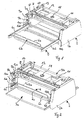
Figur 1- eine perspektivische Ansicht einer erfindungsgemäßen Vorrichtung in einer Position zur Aufnahme von Gebinden in horizontaler Richtung;
Figur 2- eine weitere perspektivische Ansicht der in Fig. 1 gezeigten Vorrichtung in einer Position zur Abgabe von Gebinden in vertikaler Richtung;
- Figur 3
- eine Ausgestaltung einer erfindungsgemäßen Anlage zum Umpositionieren von Gebinden in perspektivischer Darstellung; und
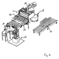
- Figur 4
- eine alternative Ausgestaltung einer erfindungsgemäßen Anlage zum Umpositionieren von Gebinden in perspektivischer Darstellung.
- FIG. 1
- a perspective view of a device according to the invention in a position for receiving containers in the horizontal direction;
- FIG. 2
- a further perspective view of the device shown in Figure 1 in a position for dispensing containers in the vertical direction.
- FIG. 3
- an embodiment of a system according to the invention for repositioning of containers in a perspective view; and
- FIG. 4
- an alternative embodiment of a system according to the invention for repositioning of containers in a perspective view.
Die in Fig. 1 gezeigte Vorrichtung 1 weist einen Grundrahmen 2 auf, der zwei seitlich angeordnete Platten 2a, 2b aufweist, die auf der Oberseite starr miteinander verbunden sind. An der Unterseite des Grundrahmens 2 sind zwei Tragbodenteile 3a und 3b, in Form zweier identisch ausgebildeter Hälften eines Tragbodens angeordnet.The
Die Vorderseite 5 der Vorrichtung weist eine Öffnung zwischen den seitlichen Platten 2a, 2b auf, durch welche ein Einbringen von Gebinden von außen in horizontaler Richtung auf die Tragbodenteile 3a, 3b möglich ist'. Gegenüber der Öffnung an der Vorderseite ist ein Schieber 6 frontseitig angeordnet. Dieser ist im Wesentlichen durch eine an einer Querleiste 6b befestigte Schiebeplatte 6ä gebildet, wobei die Querleiste 6b an beiden ihrer Enden mit einem Ende jeweils einer Seitenschiene 6c, 6d verbunden ist, so dass der Schieber 6 insgesamt im Wesentlichen eine U-Form aufweist.The front side 5 of the device has an opening between the
An ihrem jeweiligen anderen Ende sind die Seitenschienen 6c, 6d mit jeweils einer Schienenführung verbunden, welche sich entlang der Innenseite der seitlichen Platten 2a, 2b in horizontaler Richtung erstrecken. Hierdurch ist eine teleskopartige Bewegung des Schiebers bezüglich des Grundrahmens 2 in horizontaler Richtung zwischen einer äußeren und einer inneren Position möglich. Die in Fig. 1 gezeigte.Darstellung der Vorrichtung 1 entspricht dabei der äußeren Position, in welcher der Schieber 6 mit den Seitenschienen 6c, 6d im Wesentlichen vollständig außerhalb der Öffnung an der Vorderseite 5 angeordnet ist.At their respective other end, the side rails 6c, 6d are each connected to a rail guide, which extend along the inside of the
Dagegen entspricht die in Fig. 2 gezeigte Darstellung der Vorrichtung 1 der inneren Position, wobei die Seitenschienen 6c, 6d im Wesentlichen vollständig in den Innenraum eingefahren werden, so dass sich die Schiebeplatte 6a möglichst nahe an der Öffnung der Vorderseite 5 befindet, bzw. in diese eintritt.In contrast, the representation of the
Für ein automatisiertes Bewegen des teleskopartigen Schiebers 6 zwischen der äußeren und inneren Position ist ein Antrieb 7 in Form eines elektrischen Motors vorgesehen, dessen Motorkraft über eine Verteilerwelle 8 und eine Kombination von Zahnriemen 9a, 9b, 10a, 10b auf jeweils eine der Seitenschienen 6c, 6d zur horizontalen Bewegung derselben übertragen wird.For an automated movement of the
Die Tragbodenteile 3a, 3b des Tragbodens sind mittels beidseitig angeordneter Schiebelagerungen 4 ebenfalls beweglich ausgebildet, so dass sie gegeneinander verfahrbar sind. Ein automatisiertes und synchrones Bewegen der beiden Tragbodenteile 3a, 3b aufeinander zu und voneinander weg ist durch einen weiteren elektrischen Motor 11 gewährleistet, der über einen Zahnriemen eine Verteilerwelle 12 antreibt, welche auf einen jeweils beidseitig angeordneten weiteren Antriebsriemen 13 einwirkt, welcher wiederum über jeweils einen Mitnehmer mit jeweils einem der Tragbodenteile 3a, 3b wirkverbunden ist.The support base parts 3a, 3b of the support floor are also designed to be movable by means of slide bearings 4 arranged on both sides, so that they can be moved relative to one another. An automated and synchronous movement of the two support base parts 3a, 3b toward and away from each other is ensured by a further
Zum asynchronen Bewegen der beiden Tragbodenteile 3a, 3b kann in einer Weiterbildung ein zusätzlicher Motor vorgesehen sein. Somit sind auch die Tragbodenteile 3a, 3b zwischen einer äußeren und einer inneren Position verfahrbar.For asynchronous movement of the two support floor parts 3a, 3b, an additional motor may be provided in a development. Thus, the support base parts 3a, 3b are movable between an outer and an inner position.
Die in Fig. 1 gezeigte Darstellung entspricht dabei der inneren Position der Tragbodenteile 3a, 3b, bei welcher die beiden Tragbodenteile 3a, 3b vollständig zwischen den seitlichen Platten 2a, 2b des Grundrahmens 2 angeordnet sind und an einem ihrer Enden derart aneinandergrenzen, dass ein kontinuierlicher Tragboden aus den beiden Hälften gebildet ist.The representation shown in Fig. 1 corresponds to the inner position of the support base parts 3a, 3b, in which the two support base parts 3a, 3b are completely between the
In der in Fig. 2 gezeigten Darstellung, welcher der äußeren Position entspricht, sind die beiden Tragbodenteile .3a, 3b in horizontaler Richtung zur Vorder- bzw. Hinterseite hin derart gegeneinander verfahren, dass sie im Wesentlichen außerhalb des von den Platten 2a, 2b begrenzten Innenraums angeordnet sind und zwischen den Platten 2a, 2b eine Öffnung nach unten gebildet ist. Diese Position ist zur vertikalen Abgabe bzw. Aufnahme von Gebinden geeignet.In the representation shown in Fig. 2, which corresponds to the outer position, the two support base parts .3a, 3b moved in a horizontal direction to the front and rear side against each other such that they are arranged substantially outside the space bounded by the
Die Oberflächen der Tragbodenteile 3a und 3b sind aus gleitfähigen Edelstahlblechen hergestellt. Die Edelstahlbleche sind zur Verringerung der Kontaktfläche mit den aufgestellten Waren noppen- oder rillenartig geprägt oder umgeformt. Alternativ können die Oberflächen der Tragbodenteile 3a und 3b auch mit aktiv antreibbaren Förderbändern oder passiven Laufrollen ausgestattet sein.The surfaces of the support floor parts 3a and 3b are made of sliding stainless steel sheets. The stainless steel sheets are dimpled or groove shaped or reshaped to reduce the contact surface with the erected goods. Alternatively, the surfaces of the support floor parts 3a and 3b can also be equipped with actively drivable conveyor belts or passive rollers.
Zum Positionieren der aufgenommen Gebinde auf dem Tragboden ist weiterhin eine Zentriereinrichtung vorgesehen. Diese umfasst eine Seitenzentrierung, die im Wesentlichen mittels zweier entlang der Innenseiten der Platten 2a, 2b des Grundrahmens angeordneter verfahrbarer Schiebeplatten 15a, 15b realisiert ist. Dadurch wird die Aufnahme beliebig dimensionierter Gebinde an einer definierten Seitenposition ermöglicht. Zusätzlich ist an der Hinterseite der Vorrichtung zwischen den Platten 2a, 2b eine rückseitige, ebenfalls verfahrbare Schiebeplatte 16 vorgesehen, durch welche zusammen mit der teleskopartig in horizontaler Richtung verfahrbaren Schiebeplatte 6a des Schiebers 6 eine Positionierung hinsichtlich der Vorder- bzw. Hinterseite der Vorrichtung auf dem Tragboden möglich ist. Insgesamt ist also eine vierseitige Positionierung der aufgenommenen Gebinde möglich.For positioning the recorded container on the support floor, a centering device is further provided. This comprises a lateral centering, which is realized essentially by means of two movable sliding plates 15a, 15b arranged along the insides of the
Eine automatisierte synchrone Bewegung der seitlich angeordneten Schiebeplatten 15a und 15b ist durch eine Antriebseinheit 17 in Form eines Elektromotors bewerkstelligt, welcher mit einem weiteren Zahnriemen gekoppelt ist, der seinerseits mit zwei Verbindungsstücken verbunden ist. Jeweils ein Verbindungsstück ist fest mit einer der Schiebeplatten verbunden, so dass bei einem Antrieb des Zahnriemens in Abhängigkeit der Drehrichtung der Antriebseinheit die beiden Schiebeplatten 15a, 15b synchron aufeinander zu oder voneinander weg bewegt werden. Durch eine weitere Antriebseinheit (nicht gezeigt) wird auch ein automatisiertes Verstellen der rückseitigen Schiebeplatten 16 ermöglicht, wobei die Kraftübertragung ebenfalls mittels Zahnriemen erfolgt.An automated synchronous movement of the laterally arranged slide plates 15a and 15b is accomplished by a
Auf der Oberseite der Vorrichtung 1 ist eine Anschlusskupplung 18 vorgesehen, über welche eine Verbindung mit dem Arm eines Roboters hergestellt werden kann.On the upper side of the
In Fig. 3 ist eine Anlage zum Umpositionieren von Gebinden dargestellt, bei welcher die in Fig. 1 und in Fig. 2 gezeigte Vorrichtung 1 zur Aufnahme von Gebinden vorteilhaft zum Einsatz kommt. Die Aufnahmevorrichtung 1 ist am Arm 20 eines Roboters 19 befestigt, welcher die Aufnahmevorrichtung 1 oberhalb eines auf einer Palette 21 angeordneten Stapels 22 von Gebinden positioniert, wobei der Stapel 22 mittels eines Förderbandes 23 antransportiert worden ist. Ein Gebinde ist dabei durch jeweils eine Warenlage 24 des Stapels 22 gebildet. Der Schieber 6 nimmt die in Fig. 1 gezeigte äußere Position ein, welche zur Aufnahme von Gebinden vorgesehen ist. Durch die U-förmige Kontur des Schiebers 6 wird der Stapel 22 beim Absenken der Aufnahmevorrichtung 1 durch den Roboter 19 vorteilhaft umgriffen.In Fig. 3, a system for repositioning of containers is shown, in which the
Zur Höhenpositionierung der Aufnahmevorrichtung 1 auf einer Ebene zwischen zwei Warenlagen oder Gebinden 24 sind Lichtschranken als Sensoren vorgesehen, die nicht nur die Grenzebene zwischen zwei Warenlagen, sondern auch einen Zwischenraum zwischen zwei Waren oder Warengebinden in derselben Ebene erkennen können. Dazu können die Sensoren beispielsweise am vorderen Ende der Tragbodenteile 3a, 3b angeordnet sein. Diese Sensoren können entweder zusätzlich die Höhe der Lage detektieren oder es können separate Sensoren dazu vorgesehen sein, die beispielsweise an dem Grundrahmen der Aufnahmevorrichtung befestigt sind. Nachdem der Schieber 6 die entsprechende Position an der obersten Warenlage 24 eingenommen hat, kann die entsprechende Warenlage von dem Stapel 22 durch den Schieber 6 in die Aufnahmevorrichtung 1 abgezogen werden. Dabei ist zwischen jeweils 2 Warenlagen eine Trennschicht als Zwischenlage eingefügt, so dass die Warenlage von dieser Trennschicht problemlos abschiebbar ist, ohne dabei die darunterliegende Warenlage zu beeinflussen oder zu beschädigen. Derartige Zwischenlagen können beispielsweise in Form von Papier- oder Kartonlagen ausgebildet sein. Bei einfachen Waren, wie beispielsweise großflächigen Kartons, kann die Anordnung eine Zwischenlage nicht notwendig sein.For height positioning of the receiving
Nun ist es möglich, das Gebinde an einen anderen Ort mittels Verschwenken des Roboterarms 20 umzupositionieren. Daraufhin erfolgt die Abgabe des Gebindes beispielsweise auf einen anderen Stapel von Gebinden durch Absetzen der Aufnahmevorrichtung 1 auf dem Stapel und durch Verfahren der beiden Tragbodenteile 3a, 3b in die in der Fig. 2 gezeigten äußere Position.Now it is possible to reposition the container to another location by pivoting the
Die Fig. 4 zeigt eine andere Ausgestaltung einer erfindungsgemäßen Anlage zum Umpositionieren von Gebinden. Dabei ist neben dem Roboter 19 mit der erfindungsgemäßen Aufnahmevorrichtung 1 ein weiterer Roboter 25 vorgesehen, der auf einem Förderband 26 antransportierte Waren 27 zu jeweiligen Gebinden 29 zusammenstellt. Mittels eines weiteren Förderbandes 28 werden die Gebinde in den Einzugsbereich des Roboters 19 herangeführt. Dieser positioniert die Aufnahmevorrichtung 1 über dem Gebinde 29 und stellt nach dem Aufnehmen des Gebindes 29 dieses in der vorher beschriebenen Weise auf dem Stapel 30 als Warenlage ab. Nach Erreichen einer vorgesehenen Höhe des Stapels 30 mit Warenlagen wird dieser durch das Förderband 31 abtransportiert.Fig. 4 shows another embodiment of a system according to the invention for repositioning of containers. In this case, in addition to the
In einer hierzu alternativen Ausgestaltung ist vorgesehen, dass der Roboter 19 nicht zum Beladen, sondern zum Entladen des Stapels 30 eingesetzt wird. Dabei erfolgt die Aufnahme der einzelnen Warenlagen mittels des Schiebers 6 der Vorrichtung 1 in horizontaler Richtung in der oben beschriebenen Weise. Die Abgabe jeweils einer Warenlage auf das Förderband 28 erfolgt in vertikaler Richtung durch gegenseitiges Verfahren der Tragbodenteile 3a, 3b in die in der Fig. 2 gezeigten äußeren Position. Nun übernimmt der Roboter 25 das Entnehmen einzelner Waren 27 aus dem Gebinde. Dabei kann es sich beispielsweise um Neuglaspaletten, Dosenpaletten oder Paletten mit Kunststoffartikeln (PET-Flaschen) handeln. Die so entnommenen Waren können dann vereinzelnd dann beispielsweise einer Abfüllmaschine zugeführt werden.In an alternative embodiment, it is provided that the
Claims (22)
Applications Claiming Priority (1)
| Application Number | Priority Date | Filing Date | Title |
|---|---|---|---|
| DE102006047554A DE102006047554B4 (en) | 2006-10-07 | 2006-10-07 | Apparatus and method for transferring containers |
Publications (3)
| Publication Number | Publication Date |
|---|---|
| EP1908709A1 true EP1908709A1 (en) | 2008-04-09 |
| EP1908709B1 EP1908709B1 (en) | 2011-02-16 |
| EP1908709B2 EP1908709B2 (en) | 2014-10-29 |
Family
ID=38982461
Family Applications (1)
| Application Number | Title | Priority Date | Filing Date |
|---|---|---|---|
| EP07019506.0A Active EP1908709B2 (en) | 2006-10-07 | 2007-10-05 | Device for taking up and repositioning containers |
Country Status (4)
| Country | Link |
|---|---|
| EP (1) | EP1908709B2 (en) |
| AT (1) | ATE498572T1 (en) |
| DE (2) | DE102006047554B4 (en) |
| ES (1) | ES2358841T5 (en) |
Cited By (17)
| Publication number | Priority date | Publication date | Assignee | Title |
|---|---|---|---|---|
| EP2112097A1 (en) * | 2008-04-23 | 2009-10-28 | Krones AG | Method and device for transferring layers of containers to a loading station |
| DE102008020521A1 (en) * | 2008-04-23 | 2009-11-05 | Krones Ag | Bulk goods i.e. bottle bundle, layer palletizing device, has intermediate layer feeding device designed and controlled such that intermediate layers are alternatively isolatable and supplyable to palletizing device by one of feeding spaces |
| US20100014954A1 (en) * | 2008-07-17 | 2010-01-21 | Henderson Toby D | Robotic Partial Pallet Product Lifting System |
| DE102008035330A1 (en) | 2008-07-29 | 2010-02-04 | Krones Ag | Device for picking and / or relocating several palletized containers |
| ITGE20100016A1 (en) * | 2010-02-11 | 2011-08-12 | Gianluigi Rossi | "METHOD AND APPARATUS FOR PACKAGING MULTILAYERED PACKAGES ON PALLETS, PALLETS OR THE LIKE" |
| ITTO20100126A1 (en) * | 2010-02-19 | 2011-08-20 | Sidel Spa | METHOD AND SYSTEM FOR THE MANIPULATION OF ARTICLES FOR THE FORMATION OF LOAD UNITS ON PALLETS |
| WO2012118913A1 (en) * | 2011-03-01 | 2012-09-07 | Meadwestvaco Packaging Systems, Llc | Apparatus and method of manipulation of articles |
| CN103171902A (en) * | 2011-12-22 | 2013-06-26 | 西德尔合作公司 | Palletizer, palletizing method, and transfer of a layer of objects by palletizer from a conveyor to a layer depositing tool |
| US20140096480A1 (en) * | 2012-10-10 | 2014-04-10 | Hon Hai Precision Industry Co., Ltd. | Packaging device |
| DE102013218251A1 (en) | 2013-09-12 | 2015-03-12 | Krones Aktiengesellschaft | Method and device for horizontal displacement of article layers between adjacent conveyor modules |
| EP2848562A1 (en) | 2013-09-13 | 2015-03-18 | Krones Aktiengesellschaft | Method and device for horizontal movement of layers of articles between adjacent conveyor modules |
| DE102013224758A1 (en) | 2013-12-03 | 2015-06-03 | Krones Aktiengesellschaft | Palletizing device and method for its handling |
| IT201700101384A1 (en) * | 2017-09-11 | 2019-03-11 | Ocme Srl | STRIPPING LAYER GRIPPING DEVICE AND ITS LAYER TRANSFER METHOD. |
| CN111003518A (en) * | 2019-11-29 | 2020-04-14 | 中国东方电气集团有限公司 | Unstacking and stacking machine |
| WO2022103340A1 (en) | 2020-11-10 | 2022-05-19 | Transpak D.O.O. | Layering head, column palletizer and method for populating a pallet |
| CN114671178A (en) * | 2022-04-14 | 2022-06-28 | 周伟 | Logistics stacker crane |
| DE102022128001A1 (en) | 2022-10-24 | 2024-04-25 | Khs Gmbh | Palletizing robot head, palletizing robot and method for palletizing at least one layer to be palletized |
Families Citing this family (4)
| Publication number | Priority date | Publication date | Assignee | Title |
|---|---|---|---|---|
| DE102008020486B4 (en) | 2008-04-23 | 2018-08-09 | Krones Aktiengesellschaft | Device and method for palletizing piece goods compilations |
| JP6892770B2 (en) * | 2017-03-16 | 2021-06-23 | オークラ輸送機株式会社 | Hand device, article transfer device, and article removal method |
| CN113772413B (en) * | 2021-11-09 | 2022-01-28 | 杭州骏沃机电科技有限公司 | High-efficient pile up neatly device for commodity circulation |
| DE102022204784A1 (en) | 2022-05-16 | 2023-11-16 | IBG-Automation GmbH | Gripping device, system and method for picking up an open carton |
Citations (4)
| Publication number | Priority date | Publication date | Assignee | Title |
|---|---|---|---|---|
| GB2066201A (en) * | 1979-11-14 | 1981-07-08 | Holstein & Kappert Maschf | Apparatus for loading pallets |
| EP0631951A1 (en) * | 1993-06-30 | 1995-01-04 | Speciaal-Machinefabriek J.H. van Uitert B.V. | Device for lifting drums and similar objects |
| US20050063815A1 (en) * | 2001-08-01 | 2005-03-24 | Pierson Cary Michael | Palletizer puller bar |
| FR2878238A1 (en) * | 2004-11-19 | 2006-05-26 | Piers Ind Sa | Load e.g. egg stacks` row, transferring and depositing device for egg production unit, has movable chassis with base having roller blind that is retracted by juxtaposed tubular bars to permit depositing of transported load in given place |
Family Cites Families (3)
| Publication number | Priority date | Publication date | Assignee | Title |
|---|---|---|---|---|
| GB1494832A (en) * | 1974-08-23 | 1977-12-14 | Depallorator Corp Ltd | Depalletisers |
| DE4128809A1 (en) * | 1991-08-30 | 1993-03-04 | Khs Verpackungstechnik Gmbh | Pallet unloading device with side grippers - uses displaceable plate to support and remove top packs as they tilt sideways |
| US6059519A (en) * | 1999-03-12 | 2000-05-09 | Vidrala, S.A. | Container palletiser |
-
2006
- 2006-10-07 DE DE102006047554A patent/DE102006047554B4/en active Active
-
2007
- 2007-10-05 DE DE502007006493T patent/DE502007006493D1/en active Active
- 2007-10-05 AT AT07019506T patent/ATE498572T1/en active
- 2007-10-05 EP EP07019506.0A patent/EP1908709B2/en active Active
- 2007-10-05 ES ES07019506.0T patent/ES2358841T5/en active Active
Patent Citations (4)
| Publication number | Priority date | Publication date | Assignee | Title |
|---|---|---|---|---|
| GB2066201A (en) * | 1979-11-14 | 1981-07-08 | Holstein & Kappert Maschf | Apparatus for loading pallets |
| EP0631951A1 (en) * | 1993-06-30 | 1995-01-04 | Speciaal-Machinefabriek J.H. van Uitert B.V. | Device for lifting drums and similar objects |
| US20050063815A1 (en) * | 2001-08-01 | 2005-03-24 | Pierson Cary Michael | Palletizer puller bar |
| FR2878238A1 (en) * | 2004-11-19 | 2006-05-26 | Piers Ind Sa | Load e.g. egg stacks` row, transferring and depositing device for egg production unit, has movable chassis with base having roller blind that is retracted by juxtaposed tubular bars to permit depositing of transported load in given place |
Cited By (33)
| Publication number | Priority date | Publication date | Assignee | Title |
|---|---|---|---|---|
| DE102008020521A1 (en) * | 2008-04-23 | 2009-11-05 | Krones Ag | Bulk goods i.e. bottle bundle, layer palletizing device, has intermediate layer feeding device designed and controlled such that intermediate layers are alternatively isolatable and supplyable to palletizing device by one of feeding spaces |
| EP2112097A1 (en) * | 2008-04-23 | 2009-10-28 | Krones AG | Method and device for transferring layers of containers to a loading station |
| US9592970B2 (en) * | 2008-07-17 | 2017-03-14 | Toby D. Henderson | Robotic gantry with end effector for product lifting |
| US20100014954A1 (en) * | 2008-07-17 | 2010-01-21 | Henderson Toby D | Robotic Partial Pallet Product Lifting System |
| DE102008035330A1 (en) | 2008-07-29 | 2010-02-04 | Krones Ag | Device for picking and / or relocating several palletized containers |
| ITGE20100016A1 (en) * | 2010-02-11 | 2011-08-12 | Gianluigi Rossi | "METHOD AND APPARATUS FOR PACKAGING MULTILAYERED PACKAGES ON PALLETS, PALLETS OR THE LIKE" |
| ITTO20100126A1 (en) * | 2010-02-19 | 2011-08-20 | Sidel Spa | METHOD AND SYSTEM FOR THE MANIPULATION OF ARTICLES FOR THE FORMATION OF LOAD UNITS ON PALLETS |
| WO2012118913A1 (en) * | 2011-03-01 | 2012-09-07 | Meadwestvaco Packaging Systems, Llc | Apparatus and method of manipulation of articles |
| CN103764528A (en) * | 2011-03-01 | 2014-04-30 | 米德韦斯特瓦科包装系统有限责任公司 | Apparatus and method of manipulation of articles |
| CN103171902A (en) * | 2011-12-22 | 2013-06-26 | 西德尔合作公司 | Palletizer, palletizing method, and transfer of a layer of objects by palletizer from a conveyor to a layer depositing tool |
| CN103171902B (en) * | 2011-12-22 | 2016-05-04 | 意大利致博包装解决方案公司 | Palletizer, code heaping method and object layer are stacked instrument from conveyer to layer transmission by palletizer |
| US20140096480A1 (en) * | 2012-10-10 | 2014-04-10 | Hon Hai Precision Industry Co., Ltd. | Packaging device |
| US9469424B2 (en) * | 2012-10-10 | 2016-10-18 | Hong Fu Jin Precision Industry (Shenzhen) Co., Ltd. | Packaging device |
| DE102013218251A1 (en) | 2013-09-12 | 2015-03-12 | Krones Aktiengesellschaft | Method and device for horizontal displacement of article layers between adjacent conveyor modules |
| CN104512715A (en) * | 2013-09-12 | 2015-04-15 | 克罗内斯股份公司 | Device and Method for Horizontal Movement of Layers of Articles Between Adjacent Conveyor Modules |
| EP2848561A1 (en) | 2013-09-12 | 2015-03-18 | Krones Aktiengesellschaft | Method and device for horizontal movement of layers of articles between adjacent conveyor modules |
| US9290332B2 (en) | 2013-09-12 | 2016-03-22 | Krones Ag | Device and method for horizontal movement of layers of articles between adjacent conveyor modules |
| DE102013218442A1 (en) | 2013-09-13 | 2015-03-19 | Krones Aktiengesellschaft | Method and device for horizontal displacement of article layers between adjacent conveyor modules |
| EP2848562A1 (en) | 2013-09-13 | 2015-03-18 | Krones Aktiengesellschaft | Method and device for horizontal movement of layers of articles between adjacent conveyor modules |
| US9340369B2 (en) | 2013-09-13 | 2016-05-17 | Krones Ag | Device and method for horizontal movement of layers of articles between adjacent conveyor modules |
| EP2881347A1 (en) | 2013-12-03 | 2015-06-10 | Krones Aktiengesellschaft | Palletising device and method for handling it |
| DE102013224758A1 (en) | 2013-12-03 | 2015-06-03 | Krones Aktiengesellschaft | Palletizing device and method for its handling |
| US9731916B2 (en) | 2013-12-03 | 2017-08-15 | Krones, Ag | Palletizing device and method for handling thereof |
| DE102013224758B4 (en) | 2013-12-03 | 2024-04-25 | Krones Aktiengesellschaft | Palletizing device and method for handling it |
| IT201700101384A1 (en) * | 2017-09-11 | 2019-03-11 | Ocme Srl | STRIPPING LAYER GRIPPING DEVICE AND ITS LAYER TRANSFER METHOD. |
| EP3453657A1 (en) * | 2017-09-11 | 2019-03-13 | OCME S.r.l. | Sliding layer gripping device and relative layer transfer method |
| US10858204B2 (en) * | 2017-09-11 | 2020-12-08 | Ocme S.R.L. | Sliding layer gripping device and relative layer transfer method |
| CN111003518A (en) * | 2019-11-29 | 2020-04-14 | 中国东方电气集团有限公司 | Unstacking and stacking machine |
| CN111003518B (en) * | 2019-11-29 | 2021-07-30 | 中国东方电气集团有限公司 | Unstacking and stacking machine |
| WO2022103340A1 (en) | 2020-11-10 | 2022-05-19 | Transpak D.O.O. | Layering head, column palletizer and method for populating a pallet |
| CN114671178A (en) * | 2022-04-14 | 2022-06-28 | 周伟 | Logistics stacker crane |
| CN114671178B (en) * | 2022-04-14 | 2023-12-01 | 无锡翔达通用机械有限公司 | Logistics stacker |
| DE102022128001A1 (en) | 2022-10-24 | 2024-04-25 | Khs Gmbh | Palletizing robot head, palletizing robot and method for palletizing at least one layer to be palletized |
Also Published As
| Publication number | Publication date |
|---|---|
| ES2358841T3 (en) | 2011-05-16 |
| EP1908709B2 (en) | 2014-10-29 |
| ATE498572T1 (en) | 2011-03-15 |
| DE502007006493D1 (en) | 2011-03-31 |
| ES2358841T5 (en) | 2015-01-28 |
| EP1908709B1 (en) | 2011-02-16 |
| DE102006047554B4 (en) | 2010-08-12 |
| DE102006047554A1 (en) | 2008-04-10 |
Similar Documents
| Publication | Publication Date | Title |
|---|---|---|
| EP1908709B1 (en) | Method and device for taking up and repositioning containers | |
| EP1718549B1 (en) | Device for producing and palleting packaging boxes | |
| EP2637938B1 (en) | Machine for processing and/or packaging objects and method for modifying a conveying section of this machine | |
| EP3144255A1 (en) | Device for packaging piece goods combined in packaging units | |
| EP1890954B2 (en) | Method and device for depalletising stacked bundles | |
| EP2433875B2 (en) | Packaging machine | |
| CH717051B1 (en) | Process for depalletizing stacked piece goods. | |
| EP2439142B1 (en) | Device for transporting and inserting goods to be packed | |
| EP3218290A1 (en) | Method and arrangement for conveying articles, piece goods and/or containers within at least two conveying path sections | |
| EP2357145B1 (en) | Device for grouping articles | |
| DE102013113754A1 (en) | Method for forming containers and their palletizing and conveying and handling device for articles and containers | |
| EP1620338A2 (en) | Method and device for handling rod-shaped objects | |
| DE3318492A1 (en) | POSITIONING DEVICE, IN PARTICULAR PALLETISER | |
| EP1046598A1 (en) | Apparatus for making palletizable layers of packaging units | |
| DE102019128197B4 (en) | Depalletizing arrangement with a device for depalletizing stackable general cargo containers and method for depalletizing stackable general cargo containers | |
| DE102009056247A1 (en) | Device for handling large packs with a plurality of articles as package contents | |
| EP3808668B1 (en) | Device for handling items to be packaged and method for adapting a device for transporting items for packaging | |
| DE4420357A1 (en) | Magazining system for mechanical handling of palettes etc. | |
| DE3343732C2 (en) | ||
| DE102017102913A1 (en) | Apparatus and method for the flexible distribution of packaging | |
| DE202010015150U1 (en) | Device for quickly assembling commission goods for transport | |
| DE102011082747B4 (en) | Apparatus and method for loading pallets | |
| DE102019128026A1 (en) | Centering device, method for adapting a centering device and stacking and / or palletizing device | |
| WO1997011899A1 (en) | Device for transporting a layer of glass containers above a pallet | |
| DE4332377A1 (en) | Change and magazine device |
Legal Events
| Date | Code | Title | Description |
|---|---|---|---|
| PUAI | Public reference made under article 153(3) epc to a published international application that has entered the european phase |
Free format text: ORIGINAL CODE: 0009012 |
|
| AK | Designated contracting states |
Kind code of ref document: A1 Designated state(s): AT BE BG CH CY CZ DE DK EE ES FI FR GB GR HU IE IS IT LI LT LU LV MC MT NL PL PT RO SE SI SK TR |
|
| AX | Request for extension of the european patent |
Extension state: AL BA HR MK RS |
|
| 17P | Request for examination filed |
Effective date: 20080905 |
|
| AKX | Designation fees paid |
Designated state(s): AT BE BG CH CY CZ DE DK EE ES FI FR GB GR HU IE IS IT LI LT LU LV MC MT NL PL PT RO SE SI SK TR |
|
| 17Q | First examination report despatched |
Effective date: 20090122 |
|
| GRAP | Despatch of communication of intention to grant a patent |
Free format text: ORIGINAL CODE: EPIDOSNIGR1 |
|
| GRAS | Grant fee paid |
Free format text: ORIGINAL CODE: EPIDOSNIGR3 |
|
| GRAA | (expected) grant |
Free format text: ORIGINAL CODE: 0009210 |
|
| AK | Designated contracting states |
Kind code of ref document: B1 Designated state(s): AT BE BG CH CY CZ DE DK EE ES FI FR GB GR HU IE IS IT LI LT LU LV MC MT NL PL PT RO SE SI SK TR |
|
| REG | Reference to a national code |
Ref country code: GB Ref legal event code: FG4D Free format text: NOT ENGLISH |
|
| REG | Reference to a national code |
Ref country code: CH Ref legal event code: EP |
|
| REG | Reference to a national code |
Ref country code: IE Ref legal event code: FG4D Free format text: LANGUAGE OF EP DOCUMENT: GERMAN |
|
| REF | Corresponds to: |
Ref document number: 502007006493 Country of ref document: DE Date of ref document: 20110331 Kind code of ref document: P |
|
| REG | Reference to a national code |
Ref country code: DE Ref legal event code: R096 Ref document number: 502007006493 Country of ref document: DE Effective date: 20110331 |
|
| REG | Reference to a national code |
Ref country code: NL Ref legal event code: T3 |
|
| REG | Reference to a national code |
Ref country code: ES Ref legal event code: FG2A Ref document number: 2358841 Country of ref document: ES Kind code of ref document: T3 Effective date: 20110504 |
|
| LTIE | Lt: invalidation of european patent or patent extension |
Effective date: 20110216 |
|
| PG25 | Lapsed in a contracting state [announced via postgrant information from national office to epo] |
Ref country code: GR Free format text: LAPSE BECAUSE OF FAILURE TO SUBMIT A TRANSLATION OF THE DESCRIPTION OR TO PAY THE FEE WITHIN THE PRESCRIBED TIME-LIMIT Effective date: 20110517 Ref country code: LT Free format text: LAPSE BECAUSE OF FAILURE TO SUBMIT A TRANSLATION OF THE DESCRIPTION OR TO PAY THE FEE WITHIN THE PRESCRIBED TIME-LIMIT Effective date: 20110216 Ref country code: SE Free format text: LAPSE BECAUSE OF FAILURE TO SUBMIT A TRANSLATION OF THE DESCRIPTION OR TO PAY THE FEE WITHIN THE PRESCRIBED TIME-LIMIT Effective date: 20110216 Ref country code: LV Free format text: LAPSE BECAUSE OF FAILURE TO SUBMIT A TRANSLATION OF THE DESCRIPTION OR TO PAY THE FEE WITHIN THE PRESCRIBED TIME-LIMIT Effective date: 20110216 Ref country code: PT Free format text: LAPSE BECAUSE OF FAILURE TO SUBMIT A TRANSLATION OF THE DESCRIPTION OR TO PAY THE FEE WITHIN THE PRESCRIBED TIME-LIMIT Effective date: 20110616 |
|
| PG25 | Lapsed in a contracting state [announced via postgrant information from national office to epo] |
Ref country code: CY Free format text: LAPSE BECAUSE OF FAILURE TO SUBMIT A TRANSLATION OF THE DESCRIPTION OR TO PAY THE FEE WITHIN THE PRESCRIBED TIME-LIMIT Effective date: 20110216 Ref country code: BG Free format text: LAPSE BECAUSE OF FAILURE TO SUBMIT A TRANSLATION OF THE DESCRIPTION OR TO PAY THE FEE WITHIN THE PRESCRIBED TIME-LIMIT Effective date: 20110516 Ref country code: SI Free format text: LAPSE BECAUSE OF FAILURE TO SUBMIT A TRANSLATION OF THE DESCRIPTION OR TO PAY THE FEE WITHIN THE PRESCRIBED TIME-LIMIT Effective date: 20110216 Ref country code: FI Free format text: LAPSE BECAUSE OF FAILURE TO SUBMIT A TRANSLATION OF THE DESCRIPTION OR TO PAY THE FEE WITHIN THE PRESCRIBED TIME-LIMIT Effective date: 20110216 Ref country code: PL Free format text: LAPSE BECAUSE OF FAILURE TO SUBMIT A TRANSLATION OF THE DESCRIPTION OR TO PAY THE FEE WITHIN THE PRESCRIBED TIME-LIMIT Effective date: 20110216 |
|
| REG | Reference to a national code |
Ref country code: IE Ref legal event code: FD4D |
|
| PG25 | Lapsed in a contracting state [announced via postgrant information from national office to epo] |
Ref country code: EE Free format text: LAPSE BECAUSE OF FAILURE TO SUBMIT A TRANSLATION OF THE DESCRIPTION OR TO PAY THE FEE WITHIN THE PRESCRIBED TIME-LIMIT Effective date: 20110216 Ref country code: DK Free format text: LAPSE BECAUSE OF FAILURE TO SUBMIT A TRANSLATION OF THE DESCRIPTION OR TO PAY THE FEE WITHIN THE PRESCRIBED TIME-LIMIT Effective date: 20110216 Ref country code: IE Free format text: LAPSE BECAUSE OF FAILURE TO SUBMIT A TRANSLATION OF THE DESCRIPTION OR TO PAY THE FEE WITHIN THE PRESCRIBED TIME-LIMIT Effective date: 20110216 |
|
| PLBI | Opposition filed |
Free format text: ORIGINAL CODE: 0009260 |
|
| PG25 | Lapsed in a contracting state [announced via postgrant information from national office to epo] |
Ref country code: SK Free format text: LAPSE BECAUSE OF FAILURE TO SUBMIT A TRANSLATION OF THE DESCRIPTION OR TO PAY THE FEE WITHIN THE PRESCRIBED TIME-LIMIT Effective date: 20110216 Ref country code: CZ Free format text: LAPSE BECAUSE OF FAILURE TO SUBMIT A TRANSLATION OF THE DESCRIPTION OR TO PAY THE FEE WITHIN THE PRESCRIBED TIME-LIMIT Effective date: 20110216 Ref country code: RO Free format text: LAPSE BECAUSE OF FAILURE TO SUBMIT A TRANSLATION OF THE DESCRIPTION OR TO PAY THE FEE WITHIN THE PRESCRIBED TIME-LIMIT Effective date: 20110216 |
|
| PLAX | Notice of opposition and request to file observation + time limit sent |
Free format text: ORIGINAL CODE: EPIDOSNOBS2 |
|
| 26 | Opposition filed |
Opponent name: KRONES AG Effective date: 20111116 |
|
| REG | Reference to a national code |
Ref country code: DE Ref legal event code: R026 Ref document number: 502007006493 Country of ref document: DE Effective date: 20111116 |
|
| BERE | Be: lapsed |
Owner name: KUKA ROBOTER G.M.B.H. Effective date: 20111031 |
|
| PG25 | Lapsed in a contracting state [announced via postgrant information from national office to epo] |
Ref country code: IT Free format text: LAPSE BECAUSE OF FAILURE TO SUBMIT A TRANSLATION OF THE DESCRIPTION OR TO PAY THE FEE WITHIN THE PRESCRIBED TIME-LIMIT Effective date: 20110216 Ref country code: MC Free format text: LAPSE BECAUSE OF NON-PAYMENT OF DUE FEES Effective date: 20111031 |
|
| REG | Reference to a national code |
Ref country code: CH Ref legal event code: PL |
|
| PLAX | Notice of opposition and request to file observation + time limit sent |
Free format text: ORIGINAL CODE: EPIDOSNOBS2 |
|
| GBPC | Gb: european patent ceased through non-payment of renewal fee |
Effective date: 20111005 |
|
| PG25 | Lapsed in a contracting state [announced via postgrant information from national office to epo] |
Ref country code: BE Free format text: LAPSE BECAUSE OF NON-PAYMENT OF DUE FEES Effective date: 20111031 Ref country code: LI Free format text: LAPSE BECAUSE OF NON-PAYMENT OF DUE FEES Effective date: 20111031 Ref country code: CH Free format text: LAPSE BECAUSE OF NON-PAYMENT OF DUE FEES Effective date: 20111031 |
|
| PG25 | Lapsed in a contracting state [announced via postgrant information from national office to epo] |
Ref country code: GB Free format text: LAPSE BECAUSE OF NON-PAYMENT OF DUE FEES Effective date: 20111005 |
|
| PLBB | Reply of patent proprietor to notice(s) of opposition received |
Free format text: ORIGINAL CODE: EPIDOSNOBS3 |
|
| PG25 | Lapsed in a contracting state [announced via postgrant information from national office to epo] |
Ref country code: MT Free format text: LAPSE BECAUSE OF FAILURE TO SUBMIT A TRANSLATION OF THE DESCRIPTION OR TO PAY THE FEE WITHIN THE PRESCRIBED TIME-LIMIT Effective date: 20110216 |
|
| PG25 | Lapsed in a contracting state [announced via postgrant information from national office to epo] |
Ref country code: LU Free format text: LAPSE BECAUSE OF NON-PAYMENT OF DUE FEES Effective date: 20111005 |
|
| PG25 | Lapsed in a contracting state [announced via postgrant information from national office to epo] |
Ref country code: IS Free format text: LAPSE BECAUSE OF FAILURE TO SUBMIT A TRANSLATION OF THE DESCRIPTION OR TO PAY THE FEE WITHIN THE PRESCRIBED TIME-LIMIT Effective date: 20110216 |
|
| APBM | Appeal reference recorded |
Free format text: ORIGINAL CODE: EPIDOSNREFNO |
|
| APBP | Date of receipt of notice of appeal recorded |
Free format text: ORIGINAL CODE: EPIDOSNNOA2O |
|
| APAH | Appeal reference modified |
Free format text: ORIGINAL CODE: EPIDOSCREFNO |
|
| PG25 | Lapsed in a contracting state [announced via postgrant information from national office to epo] |
Ref country code: TR Free format text: LAPSE BECAUSE OF FAILURE TO SUBMIT A TRANSLATION OF THE DESCRIPTION OR TO PAY THE FEE WITHIN THE PRESCRIBED TIME-LIMIT Effective date: 20110216 |
|
| PG25 | Lapsed in a contracting state [announced via postgrant information from national office to epo] |
Ref country code: HU Free format text: LAPSE BECAUSE OF FAILURE TO SUBMIT A TRANSLATION OF THE DESCRIPTION OR TO PAY THE FEE WITHIN THE PRESCRIBED TIME-LIMIT Effective date: 20110216 |
|
| REG | Reference to a national code |
Ref country code: AT Ref legal event code: MM01 Ref document number: 498572 Country of ref document: AT Kind code of ref document: T Effective date: 20121031 |
|
| PG25 | Lapsed in a contracting state [announced via postgrant information from national office to epo] |
Ref country code: AT Free format text: LAPSE BECAUSE OF NON-PAYMENT OF DUE FEES Effective date: 20121031 |
|
| APBU | Appeal procedure closed |
Free format text: ORIGINAL CODE: EPIDOSNNOA9O |
|
| PUAH | Patent maintained in amended form |
Free format text: ORIGINAL CODE: 0009272 |
|
| STAA | Information on the status of an ep patent application or granted ep patent |
Free format text: STATUS: PATENT MAINTAINED AS AMENDED |
|
| 27A | Patent maintained in amended form |
Effective date: 20141029 |
|
| AK | Designated contracting states |
Kind code of ref document: B2 Designated state(s): AT BE BG CH CY CZ DE DK EE ES FI FR GB GR HU IE IS IT LI LT LU LV MC MT NL PL PT RO SE SI SK TR |
|
| REG | Reference to a national code |
Ref country code: DE Ref legal event code: R102 Ref document number: 502007006493 Country of ref document: DE |
|
| REG | Reference to a national code |
Ref country code: DE Ref legal event code: R102 Ref document number: 502007006493 Country of ref document: DE Effective date: 20141029 |
|
| REG | Reference to a national code |
Ref country code: NL Ref legal event code: T3 |
|
| REG | Reference to a national code |
Ref country code: ES Ref legal event code: DC2A Ref document number: 2358841 Country of ref document: ES Kind code of ref document: T5 Effective date: 20150128 |
|
| REG | Reference to a national code |
Ref country code: DE Ref legal event code: R082 Ref document number: 502007006493 Country of ref document: DE Ref country code: DE Ref legal event code: R082 Ref document number: 502007006493 Country of ref document: DE Representative=s name: WALLINGER RICKER SCHLOTTER TOSTMANN PATENT- UN, DE |
|
| REG | Reference to a national code |
Ref country code: DE Ref legal event code: R082 Ref document number: 502007006493 Country of ref document: DE |
|
| PG25 | Lapsed in a contracting state [announced via postgrant information from national office to epo] |
Ref country code: LV Free format text: LAPSE BECAUSE OF FAILURE TO SUBMIT A TRANSLATION OF THE DESCRIPTION OR TO PAY THE FEE WITHIN THE PRESCRIBED TIME-LIMIT Effective date: 20141029 |
|
| REG | Reference to a national code |
Ref country code: FR Ref legal event code: PLFP Year of fee payment: 10 |
|
| REG | Reference to a national code |
Ref country code: FR Ref legal event code: PLFP Year of fee payment: 11 |
|
| REG | Reference to a national code |
Ref country code: FR Ref legal event code: PLFP Year of fee payment: 12 |
|
| REG | Reference to a national code |
Ref country code: DE Ref legal event code: R081 Ref document number: 502007006493 Country of ref document: DE Owner name: KUKA DEUTSCHLAND GMBH, DE Free format text: FORMER OWNER: KUKA ROBOTER GMBH, 86165 AUGSBURG, DE |
|
| P01 | Opt-out of the competence of the unified patent court (upc) registered |
Effective date: 20230528 |
|
| PGFP | Annual fee paid to national office [announced via postgrant information from national office to epo] |
Ref country code: ES Payment date: 20231228 Year of fee payment: 17 |
|
| PGFP | Annual fee paid to national office [announced via postgrant information from national office to epo] |
Ref country code: NL Payment date: 20231215 Year of fee payment: 17 Ref country code: FR Payment date: 20231228 Year of fee payment: 17 Ref country code: DE Payment date: 20231128 Year of fee payment: 17 |