EP1908708A1 - Déflecteur - Google Patents
Déflecteur Download PDFInfo
- Publication number
- EP1908708A1 EP1908708A1 EP07104457A EP07104457A EP1908708A1 EP 1908708 A1 EP1908708 A1 EP 1908708A1 EP 07104457 A EP07104457 A EP 07104457A EP 07104457 A EP07104457 A EP 07104457A EP 1908708 A1 EP1908708 A1 EP 1908708A1
- Authority
- EP
- European Patent Office
- Prior art keywords
- arm
- diverter
- diverting
- arms
- drive
- Prior art date
- Legal status (The legal status is an assumption and is not a legal conclusion. Google has not performed a legal analysis and makes no representation as to the accuracy of the status listed.)
- Withdrawn
Links
- 230000000712 assembly Effects 0.000 claims abstract description 40
- 238000000429 assembly Methods 0.000 claims abstract description 40
- 230000001419 dependent effect Effects 0.000 description 8
- 230000007246 mechanism Effects 0.000 description 4
- 238000010276 construction Methods 0.000 description 3
- 239000000463 material Substances 0.000 description 3
- 238000001125 extrusion Methods 0.000 description 2
- 125000006850 spacer group Chemical group 0.000 description 2
- 241000282472 Canis lupus familiaris Species 0.000 description 1
- 229910000639 Spring steel Inorganic materials 0.000 description 1
- 239000000853 adhesive Substances 0.000 description 1
- 230000001070 adhesive effect Effects 0.000 description 1
- 229910052782 aluminium Inorganic materials 0.000 description 1
- XAGFODPZIPBFFR-UHFFFAOYSA-N aluminium Chemical compound [Al] XAGFODPZIPBFFR-UHFFFAOYSA-N 0.000 description 1
- 239000002131 composite material Substances 0.000 description 1
- 210000005069 ears Anatomy 0.000 description 1
- 230000005672 electromagnetic field Effects 0.000 description 1
- 239000006260 foam Substances 0.000 description 1
- 239000002783 friction material Substances 0.000 description 1
- 230000005484 gravity Effects 0.000 description 1
- 230000001788 irregular Effects 0.000 description 1
- 229910052751 metal Inorganic materials 0.000 description 1
- 239000002184 metal Substances 0.000 description 1
- 230000002441 reversible effect Effects 0.000 description 1
- 239000007787 solid Substances 0.000 description 1
- 230000001360 synchronised effect Effects 0.000 description 1
- 230000001960 triggered effect Effects 0.000 description 1
- 238000011144 upstream manufacturing Methods 0.000 description 1
Images


Classifications
-
- B—PERFORMING OPERATIONS; TRANSPORTING
- B65—CONVEYING; PACKING; STORING; HANDLING THIN OR FILAMENTARY MATERIAL
- B65G—TRANSPORT OR STORAGE DEVICES, e.g. CONVEYORS FOR LOADING OR TIPPING, SHOP CONVEYOR SYSTEMS OR PNEUMATIC TUBE CONVEYORS
- B65G47/00—Article or material-handling devices associated with conveyors; Methods employing such devices
- B65G47/74—Feeding, transfer, or discharging devices of particular kinds or types
- B65G47/76—Fixed or adjustable ploughs or transverse scrapers
- B65G47/766—Adjustable ploughs or transverse scrapers
Definitions
- the present invention relates to a diverter and, more particularly, to a paddle diverter for use in diverting objects, such as in a material handling system.
- the present invention provides a paddle diverter assembly used in pairs on opposed sides of a conveying surface.
- the diverter assemblies are driven by a control system that is configured to individually move the paddle diverter assembly arms so that they can be sequentially moved or a single arm can be moved to increase the through-put of the conveyor system.
- a paddle diverter assembly includes an arm and a drive system for moving the arm between a non-diverting position and a diverting position.
- the arm includes a driven diverting surface, such as a drive belt.
- the drive system comprises a driver, such as a motor, and a servo controller that selectively powers the driver to selectively move the arm of the diverter assembly.
- a driver such as a motor
- a servo controller that selectively powers the driver to selectively move the arm of the diverter assembly.
- a diverter system includes a conveying surface, a pair of diverter assemblies at opposite sides of the conveying surface, and a drive system.
- Each of the diverter assemblies comprises an arm mounted for pivotal movement between a non-diverting position, wherein the arm is adjacent the conveying surface, and a diverting position, wherein the arm is pivoted across at least a portion of the conveying surface.
- the drive system independently and selectively moves the arms between their diverting and non-diverting positions wherein the arms may be sequentially or each arm may be individually moved so that an article conveyed on the conveying surface is diverted in a diverting direction when the article contacts one of the arms when the one arm is in its diverting position.
- the drive system comprises a motor for each arm, with the motors independently actuated to independently pivot the arms.
- the drive system may comprise a controller, which selectively actuates the motors of the respective arms.
- a suitable controller may comprise a servo controller.
- each of the arms includes a driven diverting surface, such as a drive belt.
- the drive belts are driven by driven rollers, which in turn are driven by the drive system.
- each driven roller includes a driven axis about which the driven roller is driven.
- the arms pivot about respective pivot axes when pivoting between their non-diverting and diverting positions, with the driven axis of a driven roller of a respective arm being preferably generally co-linear with the pivot axis of the respective arm.
- the drive system is adapted to decouple movement of the drive belts about their driven axes from the movement of the arms about their pivot axes.
- the drive system may include separate drivers for pivoting the arms and for driving the drive belts, which are independently actuated by the drive system.
- the present invention also provides a conveyor system with diverter assemblies that are controlled in a manner that enables the spacing between objects on the conveying surface of the conveyor system to be reduced to thereby increase the through-put of the conveyor system.
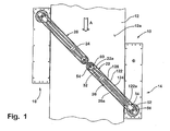
- diverter system 10 includes a conveying surface 12 and a pair of paddle diverter assemblies 14 and 16, which may be selectively actuated to divert objects conveyed on conveying surface 12a of conveyor 12 in a diverting direction, which is non-parallel with the conveying direction indicated by the arrow A in FIG. 1.
- paddle diverter assembly 16 acts as a lead diverter assembly
- paddle diverter assembly 14 acts as a lag diverter assembly.
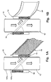
- diverter assemblies 14 and 16 may be used to divert articles onto a conveyor 18, such as a roller conveyor, which may be positioned adjacent diverter assembly 14. Alternately, diverter assemblies 14 and 16 may divert articles or objects to a discharge chute 20, such as shown in FIG. 1 B, or the like.
- paddle diverter assemblies 14 and 16 are preferably substantially identical units, which can be positioned on either side of the conveyor. For ease of reference, the description of paddle diverter assemblies 14 and 16 will be made in reference to paddle diverter assembly 14.
- paddle diverter assembly 14 includes an arm 26 that is pivotally mounted (about a pivot axis 30) to a frame 28, which is positioned adjacent conveyor 12. Further details of frame 28 will be made in reference to FIGS. 3-5 described below.
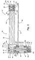
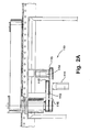
- Arm 26 includes an elongated member, preferably an aluminum extruded member 32, and an arm mount 34, which is mounted to a hollow pivot cylindrical 36 that extends through frame 28. In this manner, arm 26 is relatively light and rigid, though it should be understood that arm 26 may be formed from a solid member and/or composite member assembled from several parts. Cylinder 36 is driven about its drive axis 36a by a drive system 110 described in greater detail in reference to FIG. 2A.
- Arm mount 34 is rigidly coupled to pivot cylinder 36, for example, by fasteners 34a, so that when cylinder 36 is driven about drive axis 36a, arm 26 and pivot cylinder 36 will pivot about pivot axis 30 and drive axis 36a in unison.
- Pivot cylinder 36 is journaled in frame 28 by a cylindrical hub 40 that is mounted to frame 28.
- Frame 28 includes an upper flange or plate member 44 with an opening 44a through which pivot cylinder 36 extends.
- Cylindrical hub 40 includes an upper flange 42 that rests on the upper surface of and is secured to plate member 44 of frame 28 by, for example, fasteners.
- Cylindrical hub 40 supports a plurality of bearings, such as roller bearings 44, which journal pivot cylinder 36 and provide lateral support to pivot cylinder 36 in hub 40.
- Pivot cylinder 36 is vertically supported in hub 40 by an annular lock nut 46 that is mounted to cylinder 36 and bears on spacers 45a provided at the upper end of hub 40.
- cylindrical pivot cylinder 36 includes an enlarged shoulder 36a which bears against spacers 45b provided in the lower end of hub 40 to limit upward movement of pivot cylinder 36 in hub 40.
- a gear sprocket or pulley 48 mounted to the lower most end of pivot cylinder 36 is a gear sprocket or pulley 48, for example, by fasteners 48a, which is driven by a driver, such as a motor, which will be more fully described below in reference to drive system 110.
- a driver such as a motor
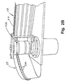
- paddle diverter assembly 14 includes a driven diverting surface, preferably a drive belt 22.
- arm 26 includes a drive pulley 52 and a slave pulley 54 for driving and supporting belt 22.
- belt 22 includes one or more guide ribs 22a that project inwardly and, further, extend into corresponding grooves 52b and 54d formed or provided in pulleys 52 and 54, respectively.
- pulleys 52 and 54 provide vertical guides and support to belt 22.
- Drive pulley 52 is mounted between the upper and lower members 56 and 58 of arm mount 34 and, further, is positioned such that its drive axis 52a is substantially collinear with pivot axis 30 of arm 26.
- Bracket 60 comprises a generally C-shaped bracket with a web or base member 62 and a pair of outwardly extending ears or flanges 64 and 66.
- Base member 62 mounts to the distal end of extruded member 32, for example, by fasteners that extend into member 32.
- Pulley 54 is mounted between flanges 64 and 66 by a shaft 54b, which is journaled in flanges 64 and 66 on bearings 68, which permit pulley 54 to rotate about its respective rotational axis 54a.
- pulley 52 is mounted in arm mount 34 on a shaft 70, which is journaled in upper member 56 of arm mount 34 and lower end 36a of pivot shaft 36 by bearings 72.
- the lower most end 70a of drive shaft 70 is coupled to a drive pulley or sprocket 74, which in turn is coupled to a driver, such as a motor, as will be more fully described below in reference to drive system 110.
- a driver such as a motor
- paddle diverter assembly 14 includes a pulley hub 54e that is mounted to lower segment 54c of pulley 54e.
- Hub 54c preferably comprises a low friction material, such as plastic, and provides a support for arm 26 at its cantilevered end in the event the arm 26 is loaded vertically downward, for example, by someone stepping on the arm.
- hub 54e protects the bearings and other components of paddle diverter assemblies 14, 16 in the even that the cantilevered end of arm 26 is loaded sufficiently to cause it to deflect.
- extruded member 32 comprises a single extrusion, which includes a plurality of transverse passageways 32a, 32b, and grooves 32c extending through member 32.
- extrusions may be used.
- drive system 110 includes a first or arm driver, such as motor 111, for driving pivot cylinder 36 and a second or belt driver, such as drive motor 114, for driving shaft 70.
- Motors 111 and 114 are mounted adjacent conveyor 12 below frame 28 and preferably comprise adjustable speed and reversible motors.
- suitable motors include servomotors, such as Series HC-KFS from Mitsubishi or are available from Dunkermotoren from Germany.
- a belt drive motor (114') may be mounted directly to the drive shaft 70a below hub 40.
- drivers may be used to move the arms, such as cylinders, including pneumatic and/or hydraulic cylinders, and/ or rotary actuators, including pneumatic or hydraulic rotary actuators, such as pneumatic motors, including servo-controlled pneumatic motors, or linear actuators, such as rack and pinion mechanisms.
- a rack may be used to rotate a curved rack or gear, which would then provide the rotational motion to the arm. Therefore, it should be understood that the term "driver" is used in its broadest sense and is not limited to a motor. However for ease of description of the preferred embodiments, reference hereinafter will be made to motor or motors.
- Motor 111 includes a drive sprocket 112 about which a drive pulley 113 extends to engage drive sprocket 48 mounted on pivot cylinder 36.
- Second motor 114 similarly includes a drive sprocket 115.
- a drive belt 116 extends around sprocket 115 for driving drive sprocket 74, which is mounted to shaft 70.
- the arm drive motor 111 includes a switch and potentiometers built into the motor and, further, are coupled to a fault indictor circuit.
- control system 120 selectively and independently actuates motors 111 and 114.
- the driven belts may be independently driven from arms 26 and, further, paddle diverters 14 and 16 may be independently pivoted between their respective diverting and non-diverting positions.
- control system 120 includes sensors to detect location and size of the object or articles conveyed on the conveying surface 12a of conveyor 12.
- control system 120 may include a pair of spaced apart sensors 121 a and 121b (FIG. 1A), such as photo eyes. Sensors 121a and 121b detect the leading edge of the article to be diverted and the tailing edge of the article so that the control system may determine the length of the article being diverted and, therefore, may determine the timing needed for the pivoting of the respective paddle diverters assemblies to minimize the time that the respective arms are pivoted across the conveying surface. In this manner, articles may be more closely placed on the conveyor and/or the conveying speed of the conveyor may be increased. As would be understood, therefore, control system 120 may operate paddle diverter assemblies asynchronously to, thereby, increase the throughput of the conveyor system.
- control system 120 uses servo control to control the position of the arms.
- control system 120 preferably includes a servo controller for each arm drive motor (111), which use feedback control loops to determine the position of the respective diverter assembly arms.
- control system 120 includes a separate servo amp and overtravel switches 122a and 122b for each arm. Suitable servo amplifiers include Series MR-J2S from Mitsubishi. In addition, this enables control system 120 to control the drivers to sequentially move the diverter arms or to individually move the diverter arms. For example, in some applications, only one arm is moved.
- switches 122a and 122b are preferably mounted to arm 26 and actuated when triggered, for example, when aligned with metal ramps or "dogs" or the like, which are mounted to hub 40 at locations that correspond to the home position for the arm and the overtravel position for the arm. Since the arms are moved between their respective home or non-diverting positions and their diverting positions without the use of mechanical stops, the orientation of the diverter assembly is unlimited by the physical configuration of the system and, instead is controlled by control system 120. Moreover, the noise generated by diverter assemblies 14, 16 is significantly reduced over the prior art.
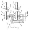
- each pair of paddle diverter assemblies includes a control unit 123, which includes the respective servo amps for each paddle diverter assembly.
- each control unit 123 may be connected, for example, by a "daisy chain" to a central controller 120a through wiring and Ethernet lines, which significantly reduces the field wiring.
- each control unit 123 includes a power supply 123a and a servo amp 123b and 123c for each diverter assembly 10.
- control unit 123 includes application dependent logic 123d, which is in communication with the servo amps and, further, with the arm drive motors (111) of the respective arms (26).
- Servo amps 123b and 123c also communicate with the respective arm drive motors (motors 111) and, further, to the overtravel and home switches of the respective arms (122a, 122b).
- arms 26 may be driven asynchronously or may be driven synchronously.
- application dependent logic 123d handles the timing of the respective arms (the lead arm and the lag arm).
- application dependent logic 123d receives input from sensors 121 a and 121 b from which the application dependent logic determines the length of the object being diverted to determine a time constant.
- the time constant varies with each size of article being diverted and is used to determine the lag time between driving the lead arm and the lag arm.
- control unit 123 may include a module 123e that can provide additional access ports to application dependent logic 123d to vary the application dependent control.
- the application dependent logic 123d may be separately and independently in communication with the arm drive motors of the leading lag arms.
- a single connection may be used to control both arms.
- control unit 123 may incorporate an actuator sensor interface 123f (ASI Bus). Actuator sensor interface 123f may provide additional information about the respective components of each paddle diverter assembly.
- control unit 123 preferably includes an opto coupler/relay 123g, which isolates the main processor from potential electrical damage from control unit 123.
- Opto coupler relay 123g interfaces with application dependent logic 123d and detects when an alarm or fault mode occurs to trigger a supervisory controller in the main control system (120a).
- Opto coupler relay 123g provides a hardware indicator to the main control system of whether the diverter assembly, namely, the arm drive motor is healthy or not so that the main control system can cut the power to the drive arm motor and also the belt drive motor.
- the control system when the respective arms of the diverter assemblies impact an article, the control system will permit the diverter to move away from the diverting position to absorb some of the impact of the article to therefore reduce the impact on the article being diverted.
- the control system provides an electrical or electronic spring for the diverter assemblies so that the output shaft of the arm drive motor of an arm may be temporarily rotated in an opposite direction from its driving direction against the force of the magnetic coil in the motor, which then is overcome by the electromagnetic field in the coil to return the arm to its diverting position.
- each of the respective arms of the diverter assemblies may include an impact plate or spring 122 mounted to the arm to also absorb some of the impact from the article.
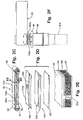
- spring 122 comprises a plate member 124, such as a spring steel plate, which extends along the longitudinal axis 26a of arm 26.
- a cushioning material 126 such as foam or the like, which further improves the impact absorbing ability of spring 122.
- Cushioning material 126 may be mounted to member 32 by a mounting plate 127, such as a plastic mounting plate, with the cushioning member 126 secured to the mounting plate by, for example, adhesive.
- Spring 122 is mounted on one end to extruded member 32 by a plurality of fasteners 122', which extend into and engage the respective grooves, for example grooves 32c of extruded member 32.
- the distal end of spring 122 is bent inwardly toward extruded member 32 and cantilevered so that when plate member 124 is compressed, the distal end of plate member 124 is free to extend along the longitudinal axis 26a of arm 26.
- plate member 124 includes a longitudinal groove 125, which receives the rib or ribs 22a of the belt 22 to provide a guide and additional vertical support to the belt 22.
- plate member 124 may comprise two or more plate sections 124a and 124b to thereby form the groove 125 there between.
- spring 122 can also be used to pre-tension belt 122.
- paddle diverter assemblies 14 and 16 may be used to divert articles from either side of the conveyor.
- paddle diverters 14 and 16 may be positioned between adjacent conveyor sections such that their respective arms can extend across the conveying surface of either adjacent conveyor.
- the control system for one of the paddle diverter assemblies may be programmed to permit the respective arm of paddle diverter assembly to pivot across the conveying surface of a central conveyor as well as the conveying surface of the adjacent conveyor section.
- the control system for the other paddle diverter assembly may be programmed to move its respective arm over the central conveyor or over an adjacent conveyor on the other side of the central conveyor.
- products conveyed on the central conveyor and flowing in the conveying direction may be diverted to the left or right by pivoting the respective arms of the paddle diverter assemblies in a counter-clockwise direction or by pivoting the arms of the paddle diverter assemblies in a clockwise direction.
- paddle diverter assemblies 14 or 16 may be used in conjunction with other diverting devices, such as pop-up rollers, in which case, the arm of the respective paddle diverter assembly extends substantially across the full width of the conveyor to divert the articles onto the rollers of the pop-up rollers so that the rollers can transfer the diverted article onto an adjacent conveyor section.
- the numeral 610 generally designates another embodiment of the diverter system of the present invention.
- Diverter system 610 includes conveyor 612 (similar to conveyor 12) and a pair of diverter assemblies 614 and 616, which are also similar paddle diverter assemblies 14 and 16.
- conveyor 612 similar to conveyor 12
- diverter assemblies 614 and 616 which are also similar paddle diverter assemblies 14 and 16.
- paddle diverter 614 which for ease of assembly and for reduction in cost is of similar or substantially identical construction to paddle diverter 616.
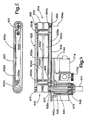
- paddle diverter assembly 614 is of similar construction to paddle diverter 14 and includes an arm 626, which supports a pair of pulleys 652 and 654 for supporting a driven surface, such as a drive belt 622.
- Arm 626 is formed by upper and lower plate members 632a and 632b, which are interconnected by vertical supports 633a and 633b.
- Pulley 654 is mounted on a drive shaft 654b, which is journaled in upper and lower plate member 632a and 632b by bearings 668 to thereby rotatably mount pulley 654 about axis 654a.
- Pulley 652 is mounted on and coupled to a drive shaft 670, which is journaled in upper plate member 632a by bearing 672 on one end and is journaled in pivot cylinder 636 by bearings 673.
- Drive shaft 670 projects through pivot cylinder 636 to be driven by a motor 671, which is directly drivingly engaged with drive shaft 670.
- pivot cylinder 636 extends through an opening 628a provided in diverter assembly frame 628 and into a hub 640, which is mounted to frame 628 by a plurality of fasteners 640a.
- Hub 640 includes a plurality of roller bearings 644, which journal pivot cylinder 636 in hub 640.
- the distal end of pivot cylinder 636 projects through hub 640 and is coupled to a drive pulley 648, which is similarly coupled by a belt or the like to a drive pulley 715 of a second motor 714, which is controlled along with motor 671 by a control system similar to control system 120.
- motor 714 is mounted to diverter assembly frame 628 by a bracket 714a. It should be understood, further, that motor 671 may be mounted on top of arm 626 to the upper end of shaft 670 to reduce the vertical extent of diverter the diverter assembly below frame 628, which may be more suitable in conveyor systems that have a lower bed height.
- belt 622 is of similar construction to belt 22 and comprises a closed loop belt with an inwardly extending rib or plurality of ribs to provide vertical guide surfaces for pulley 652 and 654.
- support arm 626 includes intermediate members 632c and 632d positioned between upper and lower plate members 632a and 632b.
- members 632c and 632d comprise channel members that are mounted to vertical supports 633a and 633b of arm 626.
- each intermediate member 632c, 632d includes an elongate transverse groove 632c' and 632d', which provides additional support to belt 622 at least on the impact side of the respective arm.
- intermediate member 632c and 632d may be provided on either side of vertical support 633a and 633b so that the diverter arm may provide the diverting surface on both sides of arms 626. Adjustment of the belts tension is achieved by mounting shaft 654b in a slotted opening 631 (FIG. 5) provided in upper plate member 632a.
- the paddle diverter assemblies of the present invention may be used in a variety of different configurations.
- the diverter assemblies may be used in groups and positioned in along one or more sides of a conveyor to provide a selectively controlled merge of products from incoming conveyors to a central main conveyor.
- the diverter assemblies may be used to block the flow of articles from an input conveyor or input conveyors or may be pivoted to open the flow of the articles from an incoming conveyor or incoming conveyors so that the articles can be merged with the articles conveyed on single conveyor.
- the diverting assemblies may be used in groups to provide multi-lane merges. For example, the diverting assemblies may be used as right angle transfer mechanisms.
- the asynchronous control of paddle diverter assemblies permits the an upstream diverter assembly to move back to its home or non-diverting position before the article is transferred over to the adjacent conveyor or the like so that articles can be conveyed more closely on the conveyor.
- the paddle diverter assemblies are particularly suitable for diverting objects with irregular or difficult configurations, such as tires. Furthermore, in this and other similar applications the drive belt may be eliminated.
- arms 26 of diverter assemblies 14 and 16 may have different lengths with their ends generally meeting at a location offset from the center of the conveying surface.
- the various aspects of the diverter assemblies may be combined with other features not specifically illustrated herein and, further, the diverter assemblies of the present invention may be used in combination with non-belt conveyors.
- the arm of the respective diverter assembly may be used in a horizontal application, such as in a pop-up diverter.
- drivers may be used to move the arms, such as cylinders, including pneumatic and/or hydraulic cylinders, and/ or rotary actuators, including pneumatic or hydraulic rotary actuators, such as pneumatic motors, including a servo-controlled pneumatic motors, or linear actuators, such as rack and pinion mechanism.
- a linear rack may be used to rotate a curved rack or gear, which would then provide the rotational motion to the arm. Therefore, it should be understood that the term "driver" is used in its broadest sense and is not limited to a motor.
Landscapes
- Engineering & Computer Science (AREA)
- Mechanical Engineering (AREA)
- Branching, Merging, And Special Transfer Between Conveyors (AREA)
- Discharge Of Articles From Conveyors (AREA)
Applications Claiming Priority (4)
| Application Number | Priority Date | Filing Date | Title |
|---|---|---|---|
| US45677703P | 2003-03-21 | 2003-03-21 | |
| US47772003P | 2003-06-11 | 2003-06-11 | |
| US10/796,917 US7124876B2 (en) | 2003-03-21 | 2004-03-10 | Diverter |
| EP04757930A EP1654177B1 (fr) | 2003-03-21 | 2004-03-19 | Deviateur |
Related Parent Applications (1)
| Application Number | Title | Priority Date | Filing Date |
|---|---|---|---|
| EP04757930A Division EP1654177B1 (fr) | 2003-03-21 | 2004-03-19 | Deviateur |
Publications (1)
| Publication Number | Publication Date |
|---|---|
| EP1908708A1 true EP1908708A1 (fr) | 2008-04-09 |
Family
ID=39148389
Family Applications (1)
| Application Number | Title | Priority Date | Filing Date |
|---|---|---|---|
| EP07104457A Withdrawn EP1908708A1 (fr) | 2003-03-21 | 2004-03-19 | Déflecteur |
Country Status (1)
| Country | Link |
|---|---|
| EP (1) | EP1908708A1 (fr) |
Cited By (1)
| Publication number | Priority date | Publication date | Assignee | Title |
|---|---|---|---|---|
| CH707448A1 (de) * | 2013-01-15 | 2014-07-15 | Ferag Ag | Förderanlage. |
Citations (1)
| Publication number | Priority date | Publication date | Assignee | Title |
|---|---|---|---|---|
| US3093236A (en) * | 1959-12-21 | 1963-06-11 | Wilkie Company | Deflector mechanism |
-
2004
- 2004-03-19 EP EP07104457A patent/EP1908708A1/fr not_active Withdrawn
Patent Citations (1)
| Publication number | Priority date | Publication date | Assignee | Title |
|---|---|---|---|---|
| US3093236A (en) * | 1959-12-21 | 1963-06-11 | Wilkie Company | Deflector mechanism |
Cited By (2)
| Publication number | Priority date | Publication date | Assignee | Title |
|---|---|---|---|---|
| CH707448A1 (de) * | 2013-01-15 | 2014-07-15 | Ferag Ag | Förderanlage. |
| WO2014110684A1 (fr) | 2013-01-15 | 2014-07-24 | Ferag Ag | Installation de transport |
Similar Documents
| Publication | Publication Date | Title |
|---|---|---|
| EP1654177B1 (fr) | Deviateur | |
| JP4504620B2 (ja) | 物品の流れの方向を転換するための装置 | |
| EP1702870B1 (fr) | Dispositif pour dérouter de façon sélective des articles d'un transporteur | |
| US7147097B2 (en) | Transverse-roller-belt sorter with automated guide | |
| JP2004522671A6 (ja) | 物品の流れの方向を転換するための装置 | |
| US5429225A (en) | Modular pneumatic accumulation conveyor and method | |
| US6619464B2 (en) | Vertical diverter assembly | |
| JP2005053647A (ja) | 転換設備 | |
| WO2007146522A1 (fr) | Dérouteur séquentiel pour transporteur à courroie étroite et procédés associés | |
| CA2130782C (fr) | Transporteur pneumatique modulaire a accumulation | |
| US6938751B1 (en) | Vertical lift assembly | |
| US20250145386A1 (en) | Right angle transfer device | |
| US6575286B1 (en) | Pop-up mail tray stop for conveyor | |
| US20090223779A1 (en) | Conveyor Diverter | |
| EP1908708A1 (fr) | Déflecteur | |
| EP1828033B1 (fr) | Dispositif pour deriver de facon selective et dans le plan lateral des produits a partir d'un convoyeur | |
| EP0749920A1 (fr) | Dispositif perfectionné pour la distribution d'articles | |
| EP1360902B1 (fr) | Appareil destine a etendre au rouleau une pate alimentaire | |
| US6390274B1 (en) | Switching apparatus for article sorting switch | |
| EP1818293A1 (fr) | Transporteur | |
| US20240166391A1 (en) | Loading Device With A Portioning Unit And Operating Method | |
| JP4594287B2 (ja) | 渡し及び振り分け装置 | |
| CN219822856U (zh) | 一种多工位联动式挡停机构 | |
| GB2324287A (en) | Aligning means for a conveyor belt | |
| JP2000211722A (ja) | 方向転換ガイドの自動ガイド幅調整装置 |
Legal Events
| Date | Code | Title | Description |
|---|---|---|---|
| PUAI | Public reference made under article 153(3) epc to a published international application that has entered the european phase |
Free format text: ORIGINAL CODE: 0009012 |
|
| 17P | Request for examination filed |
Effective date: 20070320 |
|
| AC | Divisional application: reference to earlier application |
Ref document number: 1654177 Country of ref document: EP Kind code of ref document: P |
|
| AK | Designated contracting states |
Kind code of ref document: A1 Designated state(s): AT BE BG CH CY CZ DE DK EE ES FI FR GB GR HU IE IS IT LI LT LU LV MC MT NL PL PT RO SE SI SK TR |
|
| STAA | Information on the status of an ep patent application or granted ep patent |
Free format text: STATUS: THE APPLICATION HAS BEEN WITHDRAWN |
|
| 18W | Application withdrawn |
Effective date: 20080429 |