EP1908699B1 - Container and lid combination with closing ring assembly - Google Patents
Container and lid combination with closing ring assembly Download PDFInfo
- Publication number
- EP1908699B1 EP1908699B1 EP20070253425 EP07253425A EP1908699B1 EP 1908699 B1 EP1908699 B1 EP 1908699B1 EP 20070253425 EP20070253425 EP 20070253425 EP 07253425 A EP07253425 A EP 07253425A EP 1908699 B1 EP1908699 B1 EP 1908699B1
- Authority
- EP
- European Patent Office
- Prior art keywords
- closing
- lever
- link
- ring
- container
- Prior art date
- Legal status (The legal status is an assumption and is not a legal conclusion. Google has not performed a legal analysis and makes no representation as to the accuracy of the status listed.)
- Not-in-force
Links
- 229920001971 elastomer Polymers 0.000 claims description 7
- 238000010276 construction Methods 0.000 description 9
- 230000006872 improvement Effects 0.000 description 8
- 239000002184 metal Substances 0.000 description 8
- 230000008901 benefit Effects 0.000 description 6
- 230000006870 function Effects 0.000 description 3
- 238000000034 method Methods 0.000 description 3
- 230000009471 action Effects 0.000 description 2
- 230000003466 anti-cipated effect Effects 0.000 description 2
- 230000001419 dependent effect Effects 0.000 description 2
- 230000004048 modification Effects 0.000 description 2
- 238000012986 modification Methods 0.000 description 2
- 230000002093 peripheral effect Effects 0.000 description 2
- 239000004033 plastic Substances 0.000 description 2
- 230000008569 process Effects 0.000 description 2
- 238000007789 sealing Methods 0.000 description 2
- 238000000926 separation method Methods 0.000 description 2
- 238000003466 welding Methods 0.000 description 2
- 230000004075 alteration Effects 0.000 description 1
- 238000005266 casting Methods 0.000 description 1
- 230000008859 change Effects 0.000 description 1
- 230000001010 compromised effect Effects 0.000 description 1
- 238000005520 cutting process Methods 0.000 description 1
- 239000013013 elastic material Substances 0.000 description 1
- 239000000806 elastomer Substances 0.000 description 1
- 238000005242 forging Methods 0.000 description 1
- 238000004519 manufacturing process Methods 0.000 description 1
- 230000002250 progressing effect Effects 0.000 description 1
- 230000001737 promoting effect Effects 0.000 description 1
- 230000009467 reduction Effects 0.000 description 1
- 238000004513 sizing Methods 0.000 description 1
- 238000003860 storage Methods 0.000 description 1
- 239000013598 vector Substances 0.000 description 1
Images


Classifications
-
- B—PERFORMING OPERATIONS; TRANSPORTING
- B65—CONVEYING; PACKING; STORING; HANDLING THIN OR FILAMENTARY MATERIAL
- B65D—CONTAINERS FOR STORAGE OR TRANSPORT OF ARTICLES OR MATERIALS, e.g. BAGS, BARRELS, BOTTLES, BOXES, CANS, CARTONS, CRATES, DRUMS, JARS, TANKS, HOPPERS, FORWARDING CONTAINERS; ACCESSORIES, CLOSURES, OR FITTINGS THEREFOR; PACKAGING ELEMENTS; PACKAGES
- B65D45/00—Clamping or other pressure-applying devices for securing or retaining closure members
- B65D45/32—Clamping or other pressure-applying devices for securing or retaining closure members for applying radial or radial and axial pressure, e.g. contractible bands encircling closure member
- B65D45/34—Clamping or other pressure-applying devices for securing or retaining closure members for applying radial or radial and axial pressure, e.g. contractible bands encircling closure member lever-operated
- B65D45/345—Lever-operated contractible or expansible band, the lever moving in the plane of the band
-
- Y—GENERAL TAGGING OF NEW TECHNOLOGICAL DEVELOPMENTS; GENERAL TAGGING OF CROSS-SECTIONAL TECHNOLOGIES SPANNING OVER SEVERAL SECTIONS OF THE IPC; TECHNICAL SUBJECTS COVERED BY FORMER USPC CROSS-REFERENCE ART COLLECTIONS [XRACs] AND DIGESTS
- Y10—TECHNICAL SUBJECTS COVERED BY FORMER USPC
- Y10S—TECHNICAL SUBJECTS COVERED BY FORMER USPC CROSS-REFERENCE ART COLLECTIONS [XRACs] AND DIGESTS
- Y10S292/00—Closure fasteners
- Y10S292/11—Cover fasteners
-
- Y—GENERAL TAGGING OF NEW TECHNOLOGICAL DEVELOPMENTS; GENERAL TAGGING OF CROSS-SECTIONAL TECHNOLOGIES SPANNING OVER SEVERAL SECTIONS OF THE IPC; TECHNICAL SUBJECTS COVERED BY FORMER USPC CROSS-REFERENCE ART COLLECTIONS [XRACs] AND DIGESTS
- Y10—TECHNICAL SUBJECTS COVERED BY FORMER USPC
- Y10S—TECHNICAL SUBJECTS COVERED BY FORMER USPC CROSS-REFERENCE ART COLLECTIONS [XRACs] AND DIGESTS
- Y10S292/00—Closure fasteners
- Y10S292/49—Toggle catches
-
- Y—GENERAL TAGGING OF NEW TECHNOLOGICAL DEVELOPMENTS; GENERAL TAGGING OF CROSS-SECTIONAL TECHNOLOGIES SPANNING OVER SEVERAL SECTIONS OF THE IPC; TECHNICAL SUBJECTS COVERED BY FORMER USPC CROSS-REFERENCE ART COLLECTIONS [XRACs] AND DIGESTS
- Y10—TECHNICAL SUBJECTS COVERED BY FORMER USPC
- Y10T—TECHNICAL SUBJECTS COVERED BY FORMER US CLASSIFICATION
- Y10T292/00—Closure fasteners
- Y10T292/20—Clamps
- Y10T292/205—Ring
- Y10T292/212—With expanding or contracting means
- Y10T292/216—Toggle lever
Definitions
- the present invention relates in general to a container and lid combination that uses a closing ring assembly.
- the closing ring is of the open-hoop style that can be used for open head drum-styled containers.
- Containers of the type disclosed herein may range from the smaller pail sizes of approximately 1 gallon up to much larger industrial drum sizes.
- the closing ring is used to securely attach a matching closing lid to the open end of the container.
- Containers of the type disclosed herein, formed as generally cylindrical structures with an upper, generally circular open end, are closed by tightly securing a matching lid over the open end of the container.
- the lid edge and container lip edge are clamped together by the closing ring. It is important to tightly connect the lid to the container in order to close and seal in the container contents and prevent any loss or leakage of those contents.
- the closing ring is used in cooperation with the lid and container structures for this purpose.
- the two most commonly-used closing ring structures employ either a tightening bolt arrangement or an over-center lever and linkage arrangement.
- the bolt arrangement requires manual tightening and untightening of the bolt into or out of a nut or at least an internally-threaded block.
- the torque applied to the bolt and the relative sizing of the ring body relative to the diameter of the lid dictate the degree of tightness and thus the security of the lid-to-container connection.
- the lid Once the lid is securely tightened onto the container by this bolt arrangement, it remains in position and is generally not at risk of loosening or coming apart. Perhaps the only risk in terms of loosening is due to vibration during shipment. The benefit of normally remaining tightly secured is offset by the time required to open and close the ring and thereby be able to remove or reapply the lid.
- the over-center lever and linkage arrangement uses a linkage with multiple pivots and a lever handle that is folded to close the container and unfolded or pivoted outwardly to be able to open the container by removing the lid.
- the lever handle in cooperation with the pivot points and linkage members makes use of the mechanical advantage and leverage of the structure to enable a tight closing operation, while still being performed manually.
- By enabling the manual folding of the lever handle to apply a sufficient clamping force by means of the closing ring to properly secure the lid to the container the time required to unthread or thread the clamping bolt of the other (first referenced) configuration is eliminated.
- the tighter the clamping force applied by the closing ring the greater the level of manual force that must be applied to the lever handle.
- the relative force levels depend on the configuration of the linkage and it would be an improvement to what presently exists to be able to achieve the same ring clamping (closing) force with less lever force.
- some external accessory such as a locking pin or tie is used.
- This type of accessory needs to be manually applied when the container is filled and closed and then removed at the time of initial dispensing. If the contents are not dispensed completely from the container after initial opening, and if there is some risk that the closing ring would be inadvertently opened, then the selected locking pin or tie would need to be reassembled, perhaps using a new one, and the process would then repeat itself whenever the container was opened on subsequent occasions.
- this particular approach represents a time investment that would offset some of the benefits derived from the simplicity of the fold-to-close (over-center) lever and linkage arrangement.
- the concern is that without some type of accessory feature, the traditional lever handle styles of the prior art can be inadvertently flipped up and/or over to an open condition. This could occur unintentionally and inadvertently if the lever handle is caught or hooked on some other structure. This is possible during handling, loading, shipping, storage, etc.
- the present disclosure provides another style of improvement for a closing ring assembly for a container and lid combination.
- This style of improvement is directed to a linkage design that helps to secure the ring in a closed condition.
- the improved linkage design that is disclosed enables the lever to be closed with less force, the clamping of the ring with greater closing force and more force required to raise the lever in order to open the closing ring, all as compared to the prior art linkages.
- EP 0 499 191 discloses a tightening strap with a tightening closure.
- the strap consists of an elastic material which is restorable to its original shape when deformed to ensure tightness of the closure.
- a closing ring for a container and lid combination for securing the lid to an open end of the container comprises a ring body having a first free end and a second free end, wherein the first and second free ends are drawn toward each other as part of manipulating the closing ring to secure the lid to the container, a lever pivotally connected at a first end to the first end of the ring body at a first pivot axis, the lever being constructed and arranged for opening and closing the ring body by pivoting about the first pivot axis, a link pivotally connected at a first end to the second end of the ring body and pivotally connected at a second end to the lever, and a closing structure pivotally connected at a first end to the lever at the second pivot axis and at a second end to the lever at the first pivot axis.
- One object of the present disclosure is to describe an improved container and lid combination using an improved closing ring for securing the lid to the container.
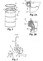
- a container assembly 20 that includes an open-end, drum-styled container 21, closed by a generally-circular matching lid 22 in cooperation with a closing ring 23.
- the closing ring 23 is a subassembly of multiple component parts that are in part welded together and in part pivotally connected or pinned, preferably by rivets, so as to pivot about the longitudinal axis of those rivets, as described herein.
- the sidewall 26 of container 21 includes a generally cylindrical, upper opening 27 surrounded by lip edge 28. Opening 27 provides access to the contents that are placed (filled) into container 21.
- the matching lid 22 is generally circular and includes a peripheral lip edge 29 that is constructed and arranged to interfit or otherwise cooperate with lip edge 28 as illustrated in FIG: 2A .
- the closing ring 23 is applied and positioned so as to fit on, over, and around the abutting edges 28 and 29.
- An annular sealing gasket 31 may be used and, if used, is positioned as illustrated in FIG. 2A .
- the edge-to-edge abutment, interfit, or cooperation of edges 28 and 29 for the metal construction is diagrammatically illustrated in FIG. 2A .
- the edge-to-edge abutment, interfit, or cooperation for a plastic pail is diagrammatically illustrated in FIG. 2B .
- Pail 30 includes lid 30a, pail body 30b, closing ring 30c, and annular sealing gasket 30d.
- FIG. 2A metal construction has been selected. This metal construction corresponds to what is illustrated in FIG. 1 .
- Closing ring 23 which as described herein is an assembly of various component parts and a subassembly of container assembly 20, includes the ring body 24, link clevis 32, two shorter links 33, lever clevis 34, lever 35, and three groupings 36b and 36c of closing links 36 (see FIG. 16 ).
- One option for shorter links 33 is to manufacture these from a unitary piece with spaced sides and a connecting portion. This alternate construction could facilitate assembly if the handling of two separate pieces is awkward.
- One of the three groupings of closing links 36 includes three links 36 that are in stacked alignment and banded together by rubber retainer 44 which is fitted around the notches 36a of the group of links 36, see FIGS. 19 and 20 .
- the other two of the three groupings of closing links 36 each include two links 36 that are in stacked alignment.
- the stack up of links 36; clevis 34, lever 35, and links 33 is illustrated in the front elevational view of FIG. 21 .
- a total of seven (7) links 36 are used.
- one option contemplated is the casting or forging of a single link for grouping 36b and single links for each of the two groupings 36c.
- the one grouping 36b is positioned on the interior of clevis 34 between the two clevis side panels.
- the side panels of lever 35 fit on the outside of the clevis 34.
- the two groupings 36c fit on the interior of lever 35 and are located (one each) on opposite sides of the single grouping 36b of three links 36.
- Links 33 are positioned on the outside of clevis 32 and on the outside of lever 35.
- An alternative closing structure as a replacement for the two groupings 36b and 36c has been conceived of for use with lever 35 and the cooperating component parts of closing ring 23.
- This alternative closing structure includes a spring member that is shaped to fit in lever 35 at the same general location of the two groupings 36b and 36c. One end of the spring member cooperates with rivet 39a for enabling the added movement in slot 40 for increased ring closing force. The other end of the spring member is pivotally connected to lever 35.
- a bent wire form can be used for this alternative closing structure.
- Clevis 32 is welded to one free end 37 of ring body 24 and clevis 34 is welded to the opposite free end 38 of ring body 24.
- Each link 33 is pivotally connected (pinned) at end 33a to clevis 32 by means of rivet 39.
- each link 33 once secured to link clevis 32 by rivet 39, is able to pivot about the longitudinal axis of rivet 39.
- End 33b of each link 33 is pivotally connected (pinned) to lever 35 by a second rivet 39a, as illustrated in FIG. 3 .
- Lever 35 is slotted in a direction along its length, producing an oblong slot 40 in each side panel of lever 35 that is in alignment with and receiving rivet 39a.
- each link 33 is able to pivotally move relative to lever 35 and lever 35 is able to pivot relative to each of the two links 33 about the longitudinal axis of rivet 39a.
- Lever 35 is pivotally connected (pinned) at one end 68 to clevis 34 by means of a shorter rivet 41. Consistent with the foregoing description, lever 35 is able to pivot about the longitudinal axis of rivet 41.
- the one grouping 36b and each one of the two groupings 36c are pivotally connected (pinned or riveted) together at their adjacent ends by rivet 42.
- the opposite end of each grouping 36c is pivotally connected to link 33 and to lever 35 by rivet 39a.
- the opposite end of grouping 36b is pivotally connected to clevis 34 and lever 35 by rivet 41.
- the distance of separation between the pivot location defined by rivet 39a within the first and second slots 40 and the pivot location defined by rivet 41 is a variable, depending on the location of rivet 39a within slots 40.
- the reference to a plurality of slots 40 is based on the fact that the lever 35 has two side panels that are spaced apart from one another and there is a corresponding slot 40 in each side panel and those two slots are aligned with each other.
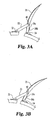
- FIGS. 3A and 3B illustrate intermediate states of ring 23 between the fully open form of FIG. 3 and the fully closed condition of FIG. 4 .
- the various component parts that have been illustrated for the closing ring 23 assembly are illustrated in FIGS. 5-18 .
- FIG. 3 the "open" condition of the closing ring 23 is illustrated.
- the positioning and connections of the individual components have been explained.
- the arrangement of linkages, their lengths, angles, and the various force vectors that are involved cause rivet 39a to position itself within oblong slots 40 in close proximity to each slot end 40a.
- This configuration contributes to the type of "folded” form of closing link groupings 36b (one) and 36c (two) with the rivet 41 location being moved away from the ring body 24.
- FIG. 3A Progressing through the stages from an open condition ( FIG. 3 ) to a fully closed condition ( FIG. 4 ), a first intermediate stage or condition is represented by FIG. 3A .
- the lever 35 has moved (i.e., pivoted) farther to the ring in a clockwise direction based up on the FIG. 3A top plan view. This action pulls on the two links 33 and draws the free ends 37 and 38 of the ring body 24 closer together.
- FIG. 3A depicts a closing ring position just as the lever 35 begins to move through the cam cross over point represented by a line drawn from the center axis of the ring body through rivet 41. The force required to move lever 35 from the FIG. 3 position to the FIG. 3A position continues to increase.
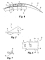
- FIG. 3B this drawing depicts the lever 35 and closing ring position and configuration after the lever 35 has passed through the cam cross over point.
- this position to the final closed condition of FIG. 4 less force is required to complete the closing process of lever 35 as compared to the force requirement in order to go from the FIG. 3A condition to the FIG. 3B condition.
- This difference in forces is due to the mechanical advantages created by the linkage arrangement and the reality of how an over-center cam arrangement is designed to function.
- the folded apex 43 begins to contact and interfere with the outer surface of the ring body 24. This interference causes the folded apex 43 to be moved in a manner that then tends to unfold or straighten out the connected groupings 36b and 36c. This manner of movement is permitted due to the presence of slots 40 and the overall length of slots 40. Importantly, the ability for groupings 36b and 36c to straighten out is dependent on the distance of slots 40 from (pivot) rivet 41. As the groupings are straightened due to interference with either the clevis 34 or the ring body 24, rivet 39a is pushed toward the opposite ends 40b of the corresponding slots 40.
- this component bands together three links 36 into grouping 36b and it also functions as a spring member.
- the lever 35 moves to a fully closed condition (see FIG. 4 )
- the three groupings 36b and 36c of links 36 straighten out to their maximum assembled (pinned) length and then fold in the opposite direction from how they are pivoted or folded in their starting orientation, such as that represented by FIG. 3 .
- This folding in the referenced opposite direction is very minor in terms of the degree of flexing, but it does occur and presents one of the reasons for incorporating a spring member such as retainer 44.
- the upper portion 44a of retainer 44 that encircles the one grouping 36b of three links 36 is pushed against the inner surface 35a of lever 35.
- lever 35 When lever 35 is moved in a counterclockwise direction in order to release the-closing ring-23-and open the container 21, it is important to ensure that the three groupings, 36b and 36c, pivot in the desired direction so as to be configured into the folded condition or orientation of FIG. 3 .
- the use of retainer 44 and its manner of placement and positioning ensures that this will occur by actually pushing on the grouping 36b in a clockwise direction.
- the opening of lever 35 follows the reverse sequence and includes the reverse movements of what occurred when lever 35 was pivoted to the closed condition of FIG. 4 .
- the maximum force exerted on the lever 35 during the ring closing operation or at least the anticipated force required for closing of a typical industrial drum is approximately 60 pounds. This is based on the selected size and style of container, lid, gasket, and closing ring as illustrated. This comparison is simply between that selected style and that same style with the closing links added and the slots introduced into lever 35. For the structure without the use of the closing links and slots, the force required to flip up lever 35 for opening is approximately 9 pounds.
- the groupings 36b and 36c are added to the linkage combination, the mechanical leverage and advantages change significantly.
- the closing force required on the lever is assisted by the action of these closing links and by the presence of slots 40. As such, the anticipated or requisite force level for closing of lever 35 is reduced to approximately 30 pounds. The force require to flip up lever 35 for opening is increased from 9 pounds up to approximately 12 pounds. Importantly, as has been noted, in addition to these force level improvements, the free ends of the closing ring are moved closer together by approximately 1/8 of an inch. This 1/8 of an inch movement is due to the two closing links and is permitted by the ability of rivet 39a to move within slots 40. It has been learned that this approximate 1/8 of an inch movement creates an increased clamping (tightening) force of the closing ring around the lid and container subassembly, thereby providing a tighter and more secure closed combination.
- the reduction in the required closing force on the lever, the increase in the required opening force on the lever, and the tighter clamping of the ring around the lid and container subassembly are all improvements to this type of container construction.
- the closing force is roughly one half of what it would be without the addition of the closing links and slot and this makes the closing task easier.
- the opening force has been increased by approximately one third and this makes inadvertent or unintentional opening less likely.
- the clamping force or tightness of the closing ring around the lid and container subassembly is greater for a more secure and more reliable closure.
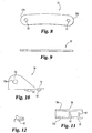
- Link clevis 32 is a unitary, metal component that includes a base 45 and opposing and spaced-apart sides 46 and 47.
- a clearance hole 46a is defined by side 46 and an aligned clearance hole 47a is defined by side 47.
- Aligned holes 46a and 47a receive rivet 39.
- the base 45 is formed with a pair of resistance weld projections 48 that melt during the welding operation to aid in rigidly and securely attaching link clevis 32 to free end 37 of ring body 24.
- the orientation of link clevis 32, as it is welded to end 37, is illustrated in FIGS. 3 and 4 .
- FIGS. 4 and 4 are set at the desired spacing or separation for the desired spacing for the two links 33.
- one link 33 is positioned against the outer surface of side 46 and the other link, in an aligned manner, is positioned against the outer surface of side 47.
- FIG. 5 is presented as a front elevational view.
- this part when this part is assembled into closing ring 23 and the ring is applied to the lid and container, this part changes to a top plan view orientation, due to how the container is oriented.
- the orientations of FIGS. 3 and 4 are looking down onto the top of the lid and container and the drawing descriptions are presented as top plan views.
- each link 33 is a substantially flat, unitary metal plate with a slight curvature to its outer edge periphery. Its length between its two pivot points (50 and 51) is selected based upon the pivot point connection locations for the linkage and the need to be able to open the closing ring 23 a sufficient amount to apply the ring and lid to the container and to remove the lid 22 from container 21. With regard to this particular relationship, putting those pivot point locations farther apart would equate to generating more clearance. However, the length is also a factor in determining how tightly the closing ring body 23 will clamp the lid 22 to the container 21. For this particular part of the overall operation, a shorter length would equate to a tighter clamping force, but it would also equate to requiring more manual force on lever 35 in order to move it to a closed condition, as is illustrated in FIG. 4 .
- Each link 33 defines a first rivet hole 50 at end 33a and a second rivet hole 51 at end 33b (see FIG. 8 ). Rivet hole 50 on one link 33 is aligned with hole 46a. Rivet hole 50 on the other link 33 is aligned with hole 47a. Once all four holes are aligned with each other, the rivet 39 is inserted through the four holes and then headed at its straight end to complete this phase of the assembly procedure in order to create this pivot point location.
- the spacing created for the two links 33 by way of the spacing between sides 46 and 47 of clevis 32, corresponds to the spacing required for the two links 33 to properly span the width or spacing of the side panels 64 and 65 of lever 35.
- Clevis 34 is a unitary, metal component that includes a base 54, and opposing, spaced-apart sides 55 and 56.
- the base 54 is formed with a pair of resistance weld projections 62 that melt during the welding operation to aid in rigidly and securely attaching lever clevis 34 to the free end 38 of ring body 24, see FIG. 3 .
- Sides 55 and 56 each define a corresponding clearance hole 55a and 56a, respectively. These two holes are aligned and cooperate with lever 35 to establish a pivot point connection for lever 35 by way of rivet 40, see FIG. 4 .
- Lever 35 is a unitary, formed metal structure that is shaped with opposing side panels 64 and 65 that define interior clearance space 66. End 67 is tapered while the opposite end 68 has a clevis configuration defined by sides 69 and 70 that extends beyond the edge 71 of outer panel 72. Sides 69 and 70 assemble over lever clevis 34 such that side 69 slides against side 56 and side 70 slides against side 55. Side 69 defines rivet hole 69a and aligned therewith, side 70 defines rivet hole 70a. When lever-35 is properly assembled onto and aligned with clevis 34, holes 55a, 56a, 69a, and 70a are all aligned in a substantially straight, axial line.
- the one grouping 36b of three links 36 that are banded together by retainer 44 are positioned on the inside of clevis 34 between sides 55 and 56.
- a first pivot hole 36d is defined by each link 36 and spaced therefrom is a second pivot hole 36e (see FIGS. 16 and 17 ).
- the three pivot holes 36d are aligned and are positioned in axial alignment with holes 55a, 56a, 69a, and 70a for receiving rivet 41.
- Side panel 64 defines a first pivot slot 40 and side panel 65 defines a second pivot slot 40 that is aligned with the first pivot slot.
- End 33b of each link 33 connects to lever 35 at the location of the first and second slots 40.
- One link 33 is positioned against the outer surface of side panel 64 while the other link 33 is positioned against the outer surface of side panel 65.
- rivet 39a is inserted.
- the straight end of rivet 39a is headed in order to secure together the two links 33 and lever 35 at this pivot point connection location.
- the two groupings 36c of two links 36 each are positioned at one end on the outside of grouping 36b and pivotally connected by rivet 42.
- the opposite end of each grouping 36c defines aligned pivot holes 36e. These four aligned pivot holes 36e are positioned in alignment with slots 40 and holes 51 in order to receive rivet 39a.
- the links and the two groupings 36c are able to pivot relative to lever 35 and lever 35 is able to pivot relative to each of the two links about-the longitudinal axis line defined by rivet 39a.
- the final pivot point location is defined by rivet 42 that connects the one grouping 36b of three links 36 with the pair of groupings 36c of two links 36 each.
- Closing link 36 is a substantially flat, unitary metal plate of uniform thickness and radiused ends.
- the main body of the closing link 36 defines a pair of spaced-apart rivet holes 36d and 36e that receive rivets, as described.
- a pair of oppositely disposed notches 36a are defined by the outer peripheral edges and centered between rivet holes 36d and 36e.
- FIG. 18 the lateral section of retainer 44 is illustrated.
- This unitary, molded part has an upper portion 44a, sides 77 and 78, and a base 79 that is severed at notch 80. Cutting through base 79 at its midpoint allows the sides to flex outwardly so that retainer 44 can be banded around the three links 36 that comprise grouping 36b and fit into notches 36a.
- the banded grouping 36b is illustrated in FIGS. 19 and 20 .
- the upper portion 44a is non-symmetrical relative to the lower portion provided by base 79.
- Retainer 44 is designed in this manner since it is the upper portion that abuts up against the inside surface of the lever 35 and it is this portion which is compressed between the lever and the upper surface of the notches 36a.
- FIG. 21 A side elevational view of the assembled combination of parts, without the required rivets, comprising closing ring 23 is illustrated in FIG. 21 .
- One alternate embodiment for closing ring 23 relates to the size and connection of groupings 36b and 36c. As illustrated in FIG. 22 , one option is to shorten the length of each link 36 in order to create alternate link 90.
- the stack of three links 90 as grouping 90a is still pivotally connected to the stack of two links 90 as grouping 90b by rivet 42.
- the rubber retainer 44 is still used as a band positioned around grouping 90a by seating in the centered notches of each link 90. With a shorter connected length, a new pivot location is required. While one end of grouping 90a is still connected to lever 35 and link 33 by rivet 39a, the free end of grouping 90b is pivotally connected to lever 35 at the pivot location defined by rivet 91.
Landscapes
- Engineering & Computer Science (AREA)
- Mechanical Engineering (AREA)
- Closures For Containers (AREA)
- Sheet Holders (AREA)
Description
- The present invention relates in general to a container and lid combination that uses a closing ring assembly. The closing ring is of the open-hoop style that can be used for open head drum-styled containers. Containers of the type disclosed herein may range from the smaller pail sizes of approximately 1 gallon up to much larger industrial drum sizes. The closing ring is used to securely attach a matching closing lid to the open end of the container. Containers of the type disclosed herein, formed as generally cylindrical structures with an upper, generally circular open end, are closed by tightly securing a matching lid over the open end of the container. The lid edge and container lip edge are clamped together by the closing ring. It is important to tightly connect the lid to the container in order to close and seal in the container contents and prevent any loss or leakage of those contents. The closing ring is used in cooperation with the lid and container structures for this purpose.
- Since the entire contents of the container may not always be dispensed when the drum (container) is first opened after initial filling, it is important to be able to re-close the container with the matching lid with substantially the same degree of security and tightness that was achieved at the time of initial filling and closing. Presently, the two most commonly-used closing ring structures employ either a tightening bolt arrangement or an over-center lever and linkage arrangement. The bolt arrangement requires manual tightening and untightening of the bolt into or out of a nut or at least an internally-threaded block. The torque applied to the bolt and the relative sizing of the ring body relative to the diameter of the lid dictate the degree of tightness and thus the security of the lid-to-container connection. Once the lid is securely tightened onto the container by this bolt arrangement, it remains in position and is generally not at risk of loosening or coming apart. Perhaps the only risk in terms of loosening is due to vibration during shipment. The benefit of normally remaining tightly secured is offset by the time required to open and close the ring and thereby be able to remove or reapply the lid.
- The over-center lever and linkage arrangement uses a linkage with multiple pivots and a lever handle that is folded to close the container and unfolded or pivoted outwardly to be able to open the container by removing the lid. The lever handle in cooperation with the pivot points and linkage members makes use of the mechanical advantage and leverage of the structure to enable a tight closing operation, while still being performed manually. By enabling the manual folding of the lever handle to apply a sufficient clamping force by means of the closing ring to properly secure the lid to the container, the time required to unthread or thread the clamping bolt of the other (first referenced) configuration is eliminated. The tighter the clamping force applied by the closing ring, the greater the level of manual force that must be applied to the lever handle. However, the relative force levels depend on the configuration of the linkage and it would be an improvement to what presently exists to be able to achieve the same ring clamping (closing) force with less lever force.
- In certain prior art structures, in order to actually secure the lever and linkage combination of the closing ring in its closed condition, some external accessory such as a locking pin or tie is used. This type of accessory needs to be manually applied when the container is filled and closed and then removed at the time of initial dispensing. If the contents are not dispensed completely from the container after initial opening, and if there is some risk that the closing ring would be inadvertently opened, then the selected locking pin or tie would need to be reassembled, perhaps using a new one, and the process would then repeat itself whenever the container was opened on subsequent occasions. Whether done once or multiple times, this particular approach represents a time investment that would offset some of the benefits derived from the simplicity of the fold-to-close (over-center) lever and linkage arrangement. The concern is that without some type of accessory feature, the traditional lever handle styles of the prior art can be inadvertently flipped up and/or over to an open condition. This could occur unintentionally and inadvertently if the lever handle is caught or hooked on some other structure. This is possible during handling, loading, shipping, storage, etc. In a recent patent application filing, it is discussed that it would be an improvement to the current state of the art in container closing rings to be able to retain the reliability and simplicity of the fold-to-close linkage but add a simple and effective securing or locking feature to prevent unintentional and inadvertent opening of the closing ring. This recent application is
U.S. Serial No. 11/268,379, filed November 7, 2005 - While this recent application discloses one style of improvement by the addition of a push button release structure, the present disclosure provides another style of improvement for a closing ring assembly for a container and lid combination. This style of improvement is directed to a linkage design that helps to secure the ring in a closed condition. The improved linkage design that is disclosed enables the lever to be closed with less force, the clamping of the ring with greater closing force and more force required to raise the lever in order to open the closing ring, all as compared to the prior art linkages.
-
EP 0 499 191 - According to the present invention there is provided a lever assembly as claimed in claim 1. Preferred features of the invention are recited in the dependent claims.
- A closing ring for a container and lid combination for securing the lid to an open end of the container according to one embodiment of the present invention comprises a ring body having a first free end and a second free end, wherein the first and second free ends are drawn toward each other as part of manipulating the closing ring to secure the lid to the container, a lever pivotally connected at a first end to the first end of the ring body at a first pivot axis, the lever being constructed and arranged for opening and closing the ring body by pivoting about the first pivot axis, a link pivotally connected at a first end to the second end of the ring body and pivotally connected at a second end to the lever, and a closing structure pivotally connected at a first end to the lever at the second pivot axis and at a second end to the lever at the first pivot axis.
- One object of the present disclosure is to describe an improved container and lid combination using an improved closing ring for securing the lid to the container.
- Preferred features of the present invention will now be described by way of example with reference to the accompanying drawings, in which:
-
FIG. 1 is an exploded, perspective view of a closing ring, container, and lid according to a typical embodiment of the present invention. -
FIG. 2A is an enlarged, partial detail of theFIG. 1 closing ring, in full section, as assembled to theFIG. 1 container and lid. -
FIG. 2B is an enlarged, partial side elevational view, in full section, of theFIG. 1 closing ring as applied to a plastic container and lid combination. -
FIG. 3 is a partial, top plan view of theFIG. 1 closing ring in an open condition, as it is applied to a container and lid. -
FIG. 3A is a partial, top plan view of theFIG. 1 closing ring in an intermediate position between the open condition ofFIG. 3 and the closed condition ofFIG. 4 . -
FIG. 3B is a partial, top plan view of theFIG. 1 closing ring in an intermediate position between the open condition ofFIG. 3 and the closed condition ofFIG. 4 . -
FIG. 4 is a partial, top plan view, in partial section, of theFIG. 1 closing ring in a closed condition. -
FIG. 5 is a front elevational view of a link clevis comprising one part of theFIG. 1 closing ring. -
FIG. 6 is a top plan view of theFIG. 5 link clevis. -
FIG. 7 is an enlarged, front elevational view, in full section, of a resistance weld projection comprising a portion of theFIG. 5 link clevis. -
FIG. 8 is a front elevational view of a link comprising a part of theFIG. 1 closing ring. -
FIG. 9 is a top plan view of theFIG. 8 link. -
FIG. 10 is a front elevational view of a lever clevis comprising one part of theFIG. 1 closing ring. -
FIG. 11 is a top plan view of theFIG. 10 lever clevis. -
FIG. 12 is an enlarged, front elevational view of a resistance weld projection comprising a portion of theFIG. 10 lever clevis. -
FIG. 13 is a front elevational view of a lever comprising a portion of theFIG. 1 closing ring. -
FIG. 14 is a top plan view of theFIG. 13 lever. -
FIG. 15 is an end elevational view, in full section, of theFIG. 13 lever. -
FIG. 16 is a top plan view of a closing link comprising one part of theFIG. 1 closing ring. -
FIG. 17 is a front elevational view of theFIG. 16 link. -
FIG. 18 is a front elevational view, in full section, of a retainer comprising one part of theFIG. 1 closing ring. -
FIG. 19 is a front elevational view of a banded grouping of closing links comprising one part of theFIG. 1 closing ring. -
FIG. 20 is a top plan view of theFIG. 19 banded grouping. -
FIG. 21 is a front elevational view of theFIG. 1 closing ring. -
FIG. 22 is a partial, top plan view of an alternative embodiment of the present invention. - For the purposes of promoting an understanding of the disclosure, reference will now be made to the embodiments illustrated in the drawings and specific language will be used to describe the same. It will nevertheless be understood that no limitation of the scope of the disclosure is thereby intended, such alterations and further modifications in the illustrated device and its use, and such further applications of the principles of the disclosure as illustrated therein being contemplated as would normally occur to one skilled in the art to which the disclosure relates.
- Referring to
FIGS. 1, 2A and 2B , there is illustrated acontainer assembly 20 that includes an open-end, drum-styledcontainer 21, closed by a generally-circular matching lid 22 in cooperation with aclosing ring 23. Theclosing ring 23 is a subassembly of multiple component parts that are in part welded together and in part pivotally connected or pinned, preferably by rivets, so as to pivot about the longitudinal axis of those rivets, as described herein. Thesidewall 26 ofcontainer 21 includes a generally cylindrical,upper opening 27 surrounded bylip edge 28.Opening 27 provides access to the contents that are placed (filled) intocontainer 21. The matchinglid 22 is generally circular and includes aperipheral lip edge 29 that is constructed and arranged to interfit or otherwise cooperate withlip edge 28 as illustrated inFIG: 2A . After thelid 22 andcontainer 21 are assembled together, theclosing ring 23 is applied and positioned so as to fit on, over, and around the abuttingedges annular sealing gasket 31 may be used and, if used, is positioned as illustrated inFIG. 2A . The edge-to-edge abutment, interfit, or cooperation ofedges FIG. 2A . The edge-to-edge abutment, interfit, or cooperation for a plastic pail is diagrammatically illustrated inFIG. 2B .Pail 30 includeslid 30a,pail body 30b, closingring 30c, andannular sealing gasket 30d. For the description of the preferred embodiment and any alternate embodiments, theFIG. 2A metal construction has been selected. This metal construction corresponds to what is illustrated inFIG. 1 . - Referring to
FIGS. 3 and4 , the structural details of closingring 23 are illustrated. Closingring 23, which as described herein is an assembly of various component parts and a subassembly ofcontainer assembly 20, includes thering body 24,link clevis 32, twoshorter links 33,lever clevis 34,lever 35, and threegroupings FIG. 16 ). One option forshorter links 33 is to manufacture these from a unitary piece with spaced sides and a connecting portion. This alternate construction could facilitate assembly if the handling of two separate pieces is awkward. One of the three groupings ofclosing links 36 includes threelinks 36 that are in stacked alignment and banded together byrubber retainer 44 which is fitted around thenotches 36a of the group oflinks 36, seeFIGS. 19 and 20 . The other two of the three groupings ofclosing links 36 each include twolinks 36 that are in stacked alignment. The stack up oflinks 36;clevis 34,lever 35, and links 33 is illustrated in the front elevational view ofFIG. 21 . A total of seven (7) links 36 are used. However, one option contemplated is the casting or forging of a single link for grouping 36b and single links for each of the twogroupings 36c. If a single link is used for grouping 36b, then that link will have a thickness corresponding to the stack of threeindividual links 36. This single link would still require thenotches 36a for purposes of receivingrubber retainer 44. As far as-the other two groupings oflinks 36, if those are changed to a double thickness link, that double thickness link would not require the notches. Considering this design option, the twogroupings - More specifically in terms of the assembly that is illustrated in
FIG. 21 , the onegrouping 36b is positioned on the interior ofclevis 34 between the two clevis side panels. The side panels oflever 35 fit on the outside of theclevis 34. The twogroupings 36c fit on the interior oflever 35 and are located (one each) on opposite sides of thesingle grouping 36b of threelinks 36.Links 33 are positioned on the outside ofclevis 32 and on the outside oflever 35. - An alternative closing structure as a replacement for the two
groupings lever 35 and the cooperating component parts of closingring 23. This alternative closing structure includes a spring member that is shaped to fit inlever 35 at the same general location of the twogroupings rivet 39a for enabling the added movement inslot 40 for increased ring closing force. The other end of the spring member is pivotally connected to lever 35. A bent wire form can be used for this alternative closing structure. -
Clevis 32 is welded to onefree end 37 ofring body 24 andclevis 34 is welded to the oppositefree end 38 ofring body 24. Eachlink 33 is pivotally connected (pinned) atend 33a to clevis 32 by means ofrivet 39. As would be understood, eachlink 33, once secured to link clevis 32 byrivet 39, is able to pivot about the longitudinal axis ofrivet 39.End 33b of eachlink 33 is pivotally connected (pinned) to lever 35 by asecond rivet 39a, as illustrated inFIG. 3 .Lever 35 is slotted in a direction along its length, producing anoblong slot 40 in each side panel oflever 35 that is in alignment with and receivingrivet 39a. Once again, as would be understood, eachlink 33 is able to pivotally move relative to lever 35 andlever 35 is able to pivot relative to each of the twolinks 33 about the longitudinal axis ofrivet 39a.Lever 35 is pivotally connected (pinned) at oneend 68 to clevis 34 by means of ashorter rivet 41. Consistent with the foregoing description,lever 35 is able to pivot about the longitudinal axis ofrivet 41. The onegrouping 36b and each one of the twogroupings 36c are pivotally connected (pinned or riveted) together at their adjacent ends byrivet 42. The opposite end of eachgrouping 36c is pivotally connected to link 33 and to lever 35 byrivet 39a. The opposite end ofgrouping 36b is pivotally connected to clevis 34 andlever 35 byrivet 41. It will be understood that the distance of separation between the pivot location defined byrivet 39a within the first andsecond slots 40 and the pivot location defined byrivet 41 is a variable, depending on the location ofrivet 39a withinslots 40. The reference to a plurality ofslots 40 is based on the fact that thelever 35 has two side panels that are spaced apart from one another and there is acorresponding slot 40 in each side panel and those two slots are aligned with each other. - When
rivet 39a is positioned at or near theend 40a of eachslot 40, the length fromrivet 39a to rivet 41 is longer than the extended (linear) combined length of the connectedgroupings links 36. This construction enables the pivotally connectedgroupings rivet 39a toward the far end ofslots 40.Rivet 39a does not abut against theend 40a ofslot 40. Some clearance remains when the twogroupings ring 23 is illustrated inFIG. 4 .FIGS. 3A and 3B illustrate intermediate states ofring 23 between the fully open form ofFIG. 3 and the fully closed condition ofFIG. 4 . The various component parts that have been illustrated for theclosing ring 23 assembly are illustrated inFIGS. 5-18 . - Referring now to
FIG. 3 , the "open" condition of theclosing ring 23 is illustrated. The positioning and connections of the individual components have been explained. The arrangement of linkages, their lengths, angles, and the various force vectors that areinvolved cause rivet 39a to position itself withinoblong slots 40 in close proximity to eachslot end 40a. This configuration contributes to the type of "folded" form of closinglink groupings 36b (one) and 36c (two) with therivet 41 location being moved away from thering body 24. - Progressing through the stages from an open condition (
FIG. 3 ) to a fully closed condition (FIG. 4 ), a first intermediate stage or condition is represented byFIG. 3A . InFIG. 3A , thelever 35 has moved (i.e., pivoted) farther to the ring in a clockwise direction based up on theFIG. 3A top plan view. This action pulls on the twolinks 33 and draws the free ends 37 and 38 of thering body 24 closer together.FIG. 3A depicts a closing ring position just as thelever 35 begins to move through the cam cross over point represented by a line drawn from the center axis of the ring body throughrivet 41. The force required to movelever 35 from theFIG. 3 position to theFIG. 3A position continues to increase. - Referring now to
FIG. 3B , this drawing depicts thelever 35 and closing ring position and configuration after thelever 35 has passed through the cam cross over point. Typically, from this position to the final closed condition ofFIG. 4 , less force is required to complete the closing process oflever 35 as compared to the force requirement in order to go from theFIG. 3A condition to theFIG. 3B condition. This difference in forces is due to the mechanical advantages created by the linkage arrangement and the reality of how an over-center cam arrangement is designed to function. - In this described progression of movement of
lever 35 fromFIG. 3 to FIG. 4 by way of the intermediate conditions ofFIGS. 3A and 3B , the pivotally connected threegroupings closing links 36 generally maintain the folded form as well as their general positional relationship relative to lever 35. It is also important to note that when the lever reverses its orientation by flipping over or passing through the cam cross over point, the folded apex 43 (at rivet 42) between theconnected groupings FIG. 3B ), rather than being pointed away from thering body 24 as illustrated inFIGS. 3 and3A . As thelever 35 is moved toward theFIG. 4 configuration, the folded apex 43 begins to contact and interfere with the outer surface of thering body 24. This interference causes the folded apex 43 to be moved in a manner that then tends to unfold or straighten out the connectedgroupings slots 40 and the overall length ofslots 40. Importantly, the ability forgroupings slots 40 from (pivot)rivet 41. As the groupings are straightened due to interference with either theclevis 34 or thering body 24,rivet 39a is pushed toward the opposite ends 40b of the correspondingslots 40. This enables the connected groupings ofclosing links 36 to hinge or flex so as to become straighter as a way to lessen or relieve the interference. As thelever 35 is closed against the ring body, the threegroupings rivet 39a toward thefar end 40b of eachslot 40. This movement ofrivet 39a is away from the location ofrivet 39 and this in turn requires that free ends 37 and 38 move closer together. This additional movement of approximately 1/8 inch is caused by the presence of the threegroupings - With regard to the use of
rubber retainer 44, this component bands together threelinks 36 intogrouping 36b and it also functions as a spring member. As thelever 35 moves to a fully closed condition (seeFIG. 4 ), the threegroupings links 36 straighten out to their maximum assembled (pinned) length and then fold in the opposite direction from how they are pivoted or folded in their starting orientation, such as that represented byFIG. 3 . This folding in the referenced opposite direction is very minor in terms of the degree of flexing, but it does occur and presents one of the reasons for incorporating a spring member such asretainer 44. As this movement occurs, theupper portion 44a ofretainer 44 that encircles the onegrouping 36b of threelinks 36, is pushed against theinner surface 35a oflever 35.Upper portion 44a is now sandwiched between the upper notch surface of each link and theinner surface 35a oflever 35 and is compressed in that position. The elastomer used forretainer 44 causes this construction and its compressed state to function as a spring, tending to want to pushgrouping 36b and thereby connectingrivet 42 in a clockwise direction based on theFIG. 4 orientation. - When
lever 35 is moved in a counterclockwise direction in order to release the-closing ring-23-and open thecontainer 21, it is important to ensure that the three groupings, 36b and 36c, pivot in the desired direction so as to be configured into the folded condition or orientation ofFIG. 3 . The use ofretainer 44 and its manner of placement and positioning ensures that this will occur by actually pushing on thegrouping 36b in a clockwise direction. The opening oflever 35 follows the reverse sequence and includes the reverse movements of what occurred whenlever 35 was pivoted to the closed condition ofFIG. 4 . - It is understood that without the use of the pivotally connected groupings of
closing links 36 and the use ofslots 40 inlever 35, the maximum force exerted on thelever 35 during the ring closing operation or at least the anticipated force required for closing of a typical industrial drum is approximately 60 pounds. This is based on the selected size and style of container, lid, gasket, and closing ring as illustrated. This comparison is simply between that selected style and that same style with the closing links added and the slots introduced intolever 35. For the structure without the use of the closing links and slots, the force required to flip uplever 35 for opening is approximately 9 pounds. When thegroupings slots 40. As such, the anticipated or requisite force level for closing oflever 35 is reduced to approximately 30 pounds. The force require to flip uplever 35 for opening is increased from 9 pounds up to approximately 12 pounds. Importantly, as has been noted, in addition to these force level improvements, the free ends of the closing ring are moved closer together by approximately 1/8 of an inch. This 1/8 of an inch movement is due to the two closing links and is permitted by the ability ofrivet 39a to move withinslots 40. It has been learned that this approximate 1/8 of an inch movement creates an increased clamping (tightening) force of the closing ring around the lid and container subassembly, thereby providing a tighter and more secure closed combination. The reduction in the required closing force on the lever, the increase in the required opening force on the lever, and the tighter clamping of the ring around the lid and container subassembly are all improvements to this type of container construction. The closing force is roughly one half of what it would be without the addition of the closing links and slot and this makes the closing task easier. The opening force has been increased by approximately one third and this makes inadvertent or unintentional opening less likely. The clamping force or tightness of the closing ring around the lid and container subassembly is greater for a more secure and more reliable closure. These improvements are made possible by the addition of the connected groupings ofclosing links 36 and by the slotting oflever 35 andspring retainer 44. - Referring now to
FIGS. 5, 6, and 7 , the details oflink clevis 32 are illustrated.Link clevis 32 is a unitary, metal component that includes abase 45 and opposing and spaced-apart sides 46 and 47. Aclearance hole 46a is defined byside 46 and an alignedclearance hole 47a is defined byside 47.Aligned holes rivet 39. Thebase 45 is formed with a pair ofresistance weld projections 48 that melt during the welding operation to aid in rigidly and securely attachinglink clevis 32 tofree end 37 ofring body 24. The orientation oflink clevis 32, as it is welded to end 37, is illustrated inFIGS. 3 and4 .Sides links 33. As is illustrated, onelink 33 is positioned against the outer surface ofside 46 and the other link, in an aligned manner, is positioned against the outer surface ofside 47. In terms of a drawing convention for the component parts and theclosing ring 23 assembly, the component parts are oriented as a separate, free-standing part. Therefore,FIG. 5 , for example, is presented as a front elevational view. However, when this part is assembled into closingring 23 and the ring is applied to the lid and container, this part changes to a top plan view orientation, due to how the container is oriented. The orientations ofFIGS. 3 and4 are looking down onto the top of the lid and container and the drawing descriptions are presented as top plan views. - Referring to
FIGS. 8 and 9 , eachlink 33 is a substantially flat, unitary metal plate with a slight curvature to its outer edge periphery. Its length between its two pivot points (50 and 51) is selected based upon the pivot point connection locations for the linkage and the need to be able to open the closing ring 23 a sufficient amount to apply the ring and lid to the container and to remove thelid 22 fromcontainer 21. With regard to this particular relationship, putting those pivot point locations farther apart would equate to generating more clearance. However, the length is also a factor in determining how tightly theclosing ring body 23 will clamp thelid 22 to thecontainer 21. For this particular part of the overall operation, a shorter length would equate to a tighter clamping force, but it would also equate to requiring more manual force onlever 35 in order to move it to a closed condition, as is illustrated inFIG. 4 . - Each
link 33 defines afirst rivet hole 50 atend 33a and asecond rivet hole 51 atend 33b (seeFIG. 8 ).Rivet hole 50 on onelink 33 is aligned withhole 46a.Rivet hole 50 on theother link 33 is aligned withhole 47a. Once all four holes are aligned with each other, therivet 39 is inserted through the four holes and then headed at its straight end to complete this phase of the assembly procedure in order to create this pivot point location. The spacing created for the twolinks 33, by way of the spacing betweensides clevis 32, corresponds to the spacing required for the twolinks 33 to properly span the width or spacing of theside panels lever 35. - Referring now to
FIGS. 10-12 , the details oflever clevis 34 are illustrated.Clevis 34 is a unitary, metal component that includes abase 54, and opposing, spaced-apart sides 55 and 56. Thebase 54 is formed with a pair ofresistance weld projections 62 that melt during the welding operation to aid in rigidly and securely attachinglever clevis 34 to thefree end 38 ofring body 24, seeFIG. 3 .Sides corresponding clearance hole lever 35 to establish a pivot point connection forlever 35 by way ofrivet 40, seeFIG. 4 . - Referring now to
FIGS. 13-15 , the details oflever 35 are illustrated.Lever 35 is a unitary, formed metal structure that is shaped with opposingside panels interior clearance space 66.End 67 is tapered while theopposite end 68 has a clevis configuration defined bysides edge 71 ofouter panel 72.Sides lever clevis 34 such thatside 69 slides againstside 56 andside 70 slides againstside 55.Side 69 definesrivet hole 69a and aligned therewith,side 70 definesrivet hole 70a. When lever-35 is properly assembled onto and aligned withclevis 34,holes rivet 41 and, once the rivet is inserted, its straight end is headed in order to secure this pivot point connection together, seeFIGS. 3 and4 . The onegrouping 36b of threelinks 36 that are banded together byretainer 44 are positioned on the inside ofclevis 34 betweensides first pivot hole 36d is defined by eachlink 36 and spaced therefrom is asecond pivot hole 36e (seeFIGS. 16 and 17 ). Forgrouping 36b, the threepivot holes 36d are aligned and are positioned in axial alignment withholes rivet 41. -
Side panel 64 defines afirst pivot slot 40 andside panel 65 defines asecond pivot slot 40 that is aligned with the first pivot slot.End 33b of eachlink 33 connects to lever 35 at the location of the first andsecond slots 40. Onelink 33 is positioned against the outer surface ofside panel 64 while theother link 33 is positioned against the outer surface ofside panel 65. Once bothholes 51 and the correspondingslots 40 are axially aligned,rivet 39a is inserted. The straight end ofrivet 39a is headed in order to secure together the twolinks 33 andlever 35 at this pivot point connection location. Additionally, the twogroupings 36c of twolinks 36 each are positioned at one end on the outside ofgrouping 36b and pivotally connected byrivet 42. The opposite end of eachgrouping 36c defines alignedpivot holes 36e. These four alignedpivot holes 36e are positioned in alignment withslots 40 and holes 51 in order to receiverivet 39a. - As would be understood, once rivets 39, 41, and 39a are each properly inserted through their corresponding set of aligned openings, a longitudinal pivot axis is created through the center of each rivet, as would be understood from the described construction and from the illustrations of
FIGS. 3 and4 . The twolinks 33 are able to pivot about the pivot axis defined byrivet 39 relative to link clevis 32 atend 37. In a similar manner,lever 35 is able to pivot about the longitudinal axis defined byrivet 41 relative to lever clevis 34 atend 38. A further pivot point location for this linkage is at the location ofrivet 39a that connects the twolinks 33 and the twogroupings 36c withlever 35. In this instance, the links and the twogroupings 36c are able to pivot relative to lever 35 andlever 35 is able to pivot relative to each of the two links about-the longitudinal axis line defined byrivet 39a. The final pivot point location is defined byrivet 42 that connects the onegrouping 36b of threelinks 36 with the pair ofgroupings 36c of twolinks 36 each. - Referring to
FIGS. 16 and 17 , the details of oneclosing link 36 are illustrated. Closinglink 36 is a substantially flat, unitary metal plate of uniform thickness and radiused ends. The main body of theclosing link 36 defines a pair of spaced-apartrivet holes disposed notches 36a are defined by the outer peripheral edges and centered betweenrivet holes - Referring now to
FIG. 18 , the lateral section ofretainer 44 is illustrated. This unitary, molded part has anupper portion 44a, sides 77 and 78, and a base 79 that is severed atnotch 80. Cutting throughbase 79 at its midpoint allows the sides to flex outwardly so thatretainer 44 can be banded around the threelinks 36 that comprise grouping 36b and fit intonotches 36a. The bandedgrouping 36b is illustrated inFIGS. 19 and 20 . As can be seen, theupper portion 44a is non-symmetrical relative to the lower portion provided bybase 79.Retainer 44 is designed in this manner since it is the upper portion that abuts up against the inside surface of thelever 35 and it is this portion which is compressed between the lever and the upper surface of thenotches 36a. - A side elevational view of the assembled combination of parts, without the required rivets, comprising closing
ring 23 is illustrated inFIG. 21 . - One alternate embodiment for closing
ring 23 relates to the size and connection ofgroupings FIG. 22 , one option is to shorten the length of eachlink 36 in order to createalternate link 90. The stack of threelinks 90 as grouping 90a is still pivotally connected to the stack of twolinks 90 asgrouping 90b byrivet 42. Therubber retainer 44 is still used as a band positioned around grouping 90a by seating in the centered notches of eachlink 90. With a shorter connected length, a new pivot location is required. While one end of grouping 90a is still connected to lever 35 and link 33 byrivet 39a, the free end ofgrouping 90b is pivotally connected to lever 35 at the pivot location defined byrivet 91. - While the preferred embodiment of the invention has been illustrated and described in the drawings and foregoing description, the same is to be considered as illustrative and not restrictive in character, it being understood that all changes and modifications that come within the scope of the claims are desired to be protected.
Claims (16)
- A lever assembly for a closing ring (23) for a container and lid combination, said lever assembly comprising:a lever (35) constructed and arranged to be pivotally connected to one end of said closing ring (23); characterised bya closing structure (36) pivotally connected at a first end with said lever (35) at a first location and pivotally connected at a second end with said lever at a second location that is spaced apart from said first location.
- The lever assembly of claim 1 wherein said closing structure includes a first closing link (36b) that is pivotally connected to a second closing link (36c).
- The lever assembly of claim 2 wherein said closing structure further including a spring-biasing structure (44) for assisting in creating a desired configuration of said first and second closing links relative to each other.
- The lever assembly of claim 3 wherein said spring-biasing structure is a rubber band assembled to said closing link.
- The lever assembly of claim 4 wherein said first closing link includes a stacked plurality of individual links, and/or wherein said second closing link includes a stacked plurality of individual links.
- A closing ring for a container and lid combination for securing the lid to an open end of said container, said closing ring comprising:a lever assembly according to any of the preceding claims;a ring body (24) having a first free end (38) and a second free end (37),wherein said first and second free ends are constructed and arranged to be drawn toward each other as part of manipulating said closing ring to secure said lid to said container,
wherein the lever is pivotally connected at a first end with said first free end of said ring body at a first pivot axis, said lever being constructed and arranged for opening and closing said ring body by pivoting about said first pivot axis; and
a link member (33) pivotally connected at a first end with said second end of said ring body and pivotally connected at a second end to said lever at a second pivot axis. - The closing ring of claim 6 wherein the first end of said closing structure is connected to said lever at said second pivot axis and the second end of said closing structure is connected to said lever at said first pivot axis.
- A closing ring according to claim 6 or 7, further comprising:a first closing link having a first end and an opposite second end;a second closing link having a first end and an opposite second end; andwherein the first end of said second closing link is pivotally connected to the second end of said first closing link, the first end of said first closing link being pivotally connected with said lever and said link member at said second pivot axis, and the second end of said second closing link being pivotally connected with said lever.
- The closing ring of claim 8 which further includes a spring-biasing structure constructed and arranged for assisting in creating a desired configuration of said first and second closing links relative to each other.
- The closing ring of claim 9 wherein said spring-biasing structure is a rubber band assembled to said closing link.
- The closing ring of any of claims 8 to 10 wherein said first closing link includes a stacked plurality of individual links, and/or wherein said second closing link includes a stacked plurality of individual links.
- The closing ring of any of claims 8 to 11 wherein the second end of the second closing link is connected with said lever at said first pivot axis.
- The closing ring of any of claims 6 to 12 wherein said lever is connected with the first end of said ring body by pivotal connection with a lever clevis member that is joined to said first end.
- The closing ring of claim 13 wherein the connection of said lever and said lever clevis member includes a lever pivot member that is inserted through said lever clevis member and through said lever.
- The closing ring of any of claims 6 to 14 wherein said link member is connected with the second end of said ring body by pivotal connection with a link clevis member that is joined to said second end.
- The closing ring of claim 15 wherein the connection of said link member and said link clevis member includes a link pivot member that is inserted through said link clevis member and through said link member.
Applications Claiming Priority (1)
| Application Number | Priority Date | Filing Date | Title |
|---|---|---|---|
| US11/542,529 US7497489B2 (en) | 2006-10-03 | 2006-10-03 | Container and lid combination with closing ring assembly |
Publications (2)
| Publication Number | Publication Date |
|---|---|
| EP1908699A1 EP1908699A1 (en) | 2008-04-09 |
| EP1908699B1 true EP1908699B1 (en) | 2010-02-24 |
Family
ID=38872633
Family Applications (1)
| Application Number | Title | Priority Date | Filing Date |
|---|---|---|---|
| EP20070253425 Not-in-force EP1908699B1 (en) | 2006-10-03 | 2007-08-30 | Container and lid combination with closing ring assembly |
Country Status (10)
| Country | Link |
|---|---|
| US (1) | US7497489B2 (en) |
| EP (1) | EP1908699B1 (en) |
| CN (1) | CN101157402A (en) |
| AR (1) | AR063108A1 (en) |
| AU (1) | AU2007214315A1 (en) |
| BR (1) | BRPI0703634A (en) |
| CA (1) | CA2599200A1 (en) |
| DE (1) | DE602007004914D1 (en) |
| ES (1) | ES2341583T3 (en) |
| MX (1) | MX2007012127A (en) |
Cited By (1)
| Publication number | Priority date | Publication date | Assignee | Title |
|---|---|---|---|---|
| EP2383198A1 (en) | 2010-04-29 | 2011-11-02 | Etablissement Levin Henri bvba | Clamping ring and barrel assembly |
Families Citing this family (23)
| Publication number | Priority date | Publication date | Assignee | Title |
|---|---|---|---|---|
| US8540102B2 (en) * | 2008-05-29 | 2013-09-24 | American Flange & Manufacturing Co., Inc. | Drum ring and lever system |
| US20110197398A1 (en) * | 2008-08-27 | 2011-08-18 | Steven John CLORLEY | Clamping band |
| US20110095027A1 (en) * | 2009-04-15 | 2011-04-28 | New Pig Corporation | Latching Drum Lid With Integral Exhaust Hood |
| RU2415060C1 (en) * | 2009-12-08 | 2011-03-27 | Закрытое Акционерное Общество "Связьстройдеталь" | Above-centre locking device |
| US8480139B2 (en) | 2009-12-16 | 2013-07-09 | New Pig Corporation | Drum band assembly |
| USD654785S1 (en) * | 2010-04-05 | 2012-02-28 | Clorley Steven John | Clamping band |
| US8985647B2 (en) * | 2010-11-05 | 2015-03-24 | Michael D. Stolzman | Integral handle locking band |
| USD647275S1 (en) * | 2011-02-04 | 2011-10-18 | Taylor Dale W | Polymer drum ring and lever with strengthened profile |
| USD703032S1 (en) * | 2011-08-10 | 2014-04-22 | Elaine Bigdeliazari | Table cloth retainer |
| US20140054905A1 (en) * | 2012-07-18 | 2014-02-27 | Container International, Inc. | Lock Ring for Securing a Container Lid |
| ES2643484T3 (en) * | 2013-12-11 | 2017-11-23 | Ardagh Mp Group Netherlands B.V. | Bucket, sealing ring, and method for mounting a bucket |
| US9855458B2 (en) | 2014-11-14 | 2018-01-02 | Tyler Scott STILSON | Clamping device |
| US9784401B1 (en) * | 2015-09-11 | 2017-10-10 | Matthew S. Edwards | Conduit repair |
| US11554903B2 (en) | 2018-09-03 | 2023-01-17 | Container International, Inc. | Container lid and lock ring combination |
| US11565143B2 (en) | 2018-11-30 | 2023-01-31 | Coulter Ventures, Llc. | Clamping device |
| USD895745S1 (en) | 2018-11-30 | 2020-09-08 | Coulter Ventures, Llc. | Collar |
| US12066045B2 (en) | 2019-07-02 | 2024-08-20 | Coulter Ventures, Llc. | Clamping device |
| USD919422S1 (en) | 2019-09-04 | 2021-05-18 | Coulter Ventures, Llc. | Clamping device |
| USD971720S1 (en) | 2020-01-09 | 2022-12-06 | Coulter Ventures, Llc. | Collar |
| DE102020102770B4 (en) * | 2020-02-04 | 2022-09-29 | Gero Vertriebs-Gmbh | grip element |
| CN111661476A (en) * | 2020-06-30 | 2020-09-15 | 杭州上许塑料制品有限公司 | Packaging can sealing cover |
| CN113859811B (en) * | 2021-09-23 | 2023-10-17 | 杜远 | Outdoor garbage support capable of being plugged in ground |
| WO2024129526A1 (en) * | 2022-12-16 | 2024-06-20 | Qualitas Manufacturing Incorporated | Rolling shutter cam lock slat |
Family Cites Families (42)
| Publication number | Priority date | Publication date | Assignee | Title |
|---|---|---|---|---|
| US1482049A (en) * | 1922-06-03 | 1924-01-29 | Abram G Cox | Closure construction for pressure cookers |
| US2108407A (en) * | 1935-05-02 | 1938-02-15 | Cornell Securities Corp | Receptacle and closure |
| US2087732A (en) * | 1935-05-02 | 1937-07-20 | Cornell Securities Corp | Receptacle and closure |
| US2237479A (en) * | 1938-11-05 | 1941-04-08 | Wilson & Bennett Mfg Company | Container closure |
| US2236439A (en) * | 1940-04-04 | 1941-03-25 | Frank L Mckenna | Clamp |
| US2703431A (en) * | 1953-01-12 | 1955-03-08 | Jean H Tatom | Latch hinge |
| DE1181623B (en) | 1960-09-06 | 1964-11-12 | Mead Corp | Tension ring fastener |
| US3246793A (en) * | 1965-09-07 | 1966-04-19 | Charles E Wade | Sealing closure |
| DE2039548C3 (en) | 1970-08-08 | 1978-11-02 | Basf Farben + Fasern Ag, 2000 Hamburg | Locking device for tension ring locks |
| US3897884A (en) * | 1973-05-15 | 1975-08-05 | Richard F Lankenau | Drum closure |
| US3889852A (en) * | 1973-08-06 | 1975-06-17 | Peter Strefford | Container safety dispensing closure |
| US3997072A (en) * | 1975-02-24 | 1976-12-14 | General Electric Company | Compactor container with removable bottom |
| NL7600769A (en) * | 1975-03-03 | 1976-09-07 | Hardt Walter | DEVICE FOR PROTECTING FUSES AGAINST UNAUTHORIZED UPWARDS OF AN ARMOR OF A ROLLING SHUTTER. |
| DE7512896U (en) | 1975-04-22 | 1977-02-24 | Moeller & Co Metallwaren | Tension ring with lock |
| US4101156A (en) * | 1976-05-28 | 1978-07-18 | Greif Bros. Corporation | Clamping ring for removable covers of drums |
| US4033454A (en) * | 1976-07-06 | 1977-07-05 | Greif Bros. Corporation | Method and structure for retaining shipping drums on pallets |
| US4350031A (en) * | 1976-12-14 | 1982-09-21 | Junichi Shimono | Pushbutton operated door locks |
| CH614416A5 (en) * | 1977-05-23 | 1979-11-30 | Mueller Ernst Ag | |
| US4318557A (en) * | 1979-10-09 | 1982-03-09 | Hartwell Corporation | Latching mechanism |
| US4294377A (en) * | 1980-03-14 | 1981-10-13 | Chen Shin I | Constant pressure cooker and fastener |
| US4828299A (en) * | 1987-03-31 | 1989-05-09 | Hartwell Corporation | Latch |
| DE8806922U1 (en) | 1988-05-27 | 1989-09-28 | Reichstadt, Hans Udo, 5628 Heiligenhaus | Clamping ring closure |
| NL8802456A (en) * | 1988-10-06 | 1990-05-01 | Wavin Bv | Injection-molded plastic cover for a barrel as well as a barrel with such an injection-molded plastic cover. |
| DE8815876U1 (en) * | 1988-12-22 | 1989-02-02 | Mauser-Werke GmbH, 5040 Brühl | Clamping ring closure |
| DE3924594A1 (en) | 1989-07-25 | 1991-02-07 | Schmalbach Lubeca | TENSION RING LOCK FOR CONTAINERS OF SHEET, LIKE BUCKET, HOBBOCK OR THE LIKE, WITH A PUSH-IN LID |
| DE3933995A1 (en) | 1989-10-11 | 1991-04-25 | Moeller Gmbh & Co Kg | Fastening for tension ring - has U=shaped connection and tension lever, with hook |
| EP0544684A4 (en) * | 1990-07-13 | 1993-09-29 | Henricus Johannes Van Rijswijk | Toggle latch |
| DE9101683U1 (en) | 1991-02-14 | 1992-06-11 | Schemm GmbH, 5952 Attendorn | Clamping ring |
| IT221710Z2 (en) * | 1991-05-07 | 1994-09-16 | Reina Giancarlo | STRUCTURE OF FASTENING RING FOR TIGHTENING A COVER TO A CONTAINER |
| US5129537A (en) * | 1991-06-11 | 1992-07-14 | Bordner Paul G | Two-piece polymeric lid clamping ring |
| US5284270A (en) * | 1991-08-02 | 1994-02-08 | Self Industries, Inc. | Lever latch ring for securing a cover panel to a container |
| DE9204571U1 (en) | 1992-04-03 | 1992-06-25 | Schemm GmbH, 5952 Attendorn | Tension strap |
| US5411162A (en) * | 1992-07-31 | 1995-05-02 | Allen-Bradley Company, Inc. | V-band coupling for an explosion-proof enclosure |
| US5299707A (en) * | 1992-09-29 | 1994-04-05 | Stolzman Michael D | Welded cover lock |
| US5713482A (en) * | 1996-05-02 | 1998-02-03 | Container Accessories, Inc. | Polymeric split ring clamp |
| DE19746509C2 (en) * | 1997-10-22 | 2003-03-27 | Amc Int Alfa Metalcraft Corp | cooking vessel |
| US5947320A (en) * | 1997-12-11 | 1999-09-07 | Containers Accessories, Inc. | Molded drum, lid and ring-clamp system with enhanced containment integrity |
| US6007120A (en) * | 1998-07-09 | 1999-12-28 | Vogt; Randall L. | Clamping ring with removable handle |
| US6435576B1 (en) * | 1999-07-19 | 2002-08-20 | Lenix Fred Kusta | Closure ring assembly for an open-head drum |
| AUPQ999400A0 (en) | 2000-09-08 | 2000-10-05 | Visy Packaging Pty Ltd | Container, container lid and locking ring |
| AT411051B (en) | 2002-01-02 | 2003-09-25 | Fries Planung & Marketing | HAZARDOUS CONTAINERS FOR LIQUID, IN PARTICULAR CEMENTIC, HAZARDOUS HAZARDOUS GOODS |
| US7802827B2 (en) | 2005-11-07 | 2010-09-28 | Rieke Corporation | Closing ring for lid and container combination |
-
2006
- 2006-10-03 US US11/542,529 patent/US7497489B2/en not_active Expired - Fee Related
-
2007
- 2007-08-28 CA CA 2599200 patent/CA2599200A1/en not_active Abandoned
- 2007-08-30 DE DE200760004914 patent/DE602007004914D1/en active Active
- 2007-08-30 ES ES07253425T patent/ES2341583T3/en active Active
- 2007-08-30 EP EP20070253425 patent/EP1908699B1/en not_active Not-in-force
- 2007-08-30 AU AU2007214315A patent/AU2007214315A1/en not_active Abandoned
- 2007-09-11 BR BRPI0703634-5A patent/BRPI0703634A/en not_active Application Discontinuation
- 2007-09-28 MX MX2007012127A patent/MX2007012127A/en active IP Right Grant
- 2007-09-30 CN CNA2007101630836A patent/CN101157402A/en active Pending
- 2007-10-02 AR ARP070104371 patent/AR063108A1/en not_active Application Discontinuation
Cited By (1)
| Publication number | Priority date | Publication date | Assignee | Title |
|---|---|---|---|---|
| EP2383198A1 (en) | 2010-04-29 | 2011-11-02 | Etablissement Levin Henri bvba | Clamping ring and barrel assembly |
Also Published As
| Publication number | Publication date |
|---|---|
| US7497489B2 (en) | 2009-03-03 |
| CN101157402A (en) | 2008-04-09 |
| CA2599200A1 (en) | 2008-04-03 |
| BRPI0703634A (en) | 2008-06-03 |
| DE602007004914D1 (en) | 2010-04-08 |
| AU2007214315A1 (en) | 2008-04-17 |
| EP1908699A1 (en) | 2008-04-09 |
| AR063108A1 (en) | 2008-12-30 |
| US20080079265A1 (en) | 2008-04-03 |
| ES2341583T3 (en) | 2010-06-22 |
| MX2007012127A (en) | 2009-02-19 |
Similar Documents
| Publication | Publication Date | Title |
|---|---|---|
| EP1908699B1 (en) | Container and lid combination with closing ring assembly | |
| CA2565656C (en) | Closing ring for lid and container combination | |
| JP6539660B2 (en) | Container, closing ring, and method of assembling container | |
| KR20090099057A (en) | Packaging including containers coupled with lids with reversible, reusable locking means | |
| EP0954494B1 (en) | Spray can actuator with enhanced attachment mechanism | |
| US20140305942A1 (en) | Closing Element and Container Provided with Such a Closing Element | |
| JP2012502856A (en) | Package with liquid leakage prevention switch | |
| US9265307B2 (en) | Strap guide insert | |
| US5295604A (en) | Toggle latch | |
| US7350760B2 (en) | Clamp for concrete forms | |
| CZ285240B6 (en) | Self-locking clip | |
| US20110197398A1 (en) | Clamping band | |
| JP2000289376A (en) | Binder for fixing back part | |
| US8839978B2 (en) | Tether and closure assembly including same | |
| AU2022270196B2 (en) | Systems and methods for a dual hook flat strap attachment device | |
| US20230340816A1 (en) | Tension Lock for Assembly Without Tools and System for Assembly of a Tension Lock Without Tools | |
| WO2018039219A1 (en) | Container and method of removing a lid from a container | |
| EP0659144B1 (en) | Locking device for separable parts | |
| CN114269300A (en) | Closure device for orthoses | |
| JPH06298268A (en) | Cover-fastening band for open can | |
| AU640030B2 (en) | Toggle latch | |
| WO2007102231A1 (en) | Binding device | |
| JP2000025809A (en) | Tightening band for square pail can | |
| JP2000016447A (en) | Fastening band | |
| GB2047789A (en) | A fastener |
Legal Events
| Date | Code | Title | Description |
|---|---|---|---|
| PUAI | Public reference made under article 153(3) epc to a published international application that has entered the european phase |
Free format text: ORIGINAL CODE: 0009012 |
|
| AK | Designated contracting states |
Kind code of ref document: A1 Designated state(s): AT BE BG CH CY CZ DE DK EE ES FI FR GB GR HU IE IS IT LI LT LU LV MC MT NL PL PT RO SE SI SK TR |
|
| AX | Request for extension of the european patent |
Extension state: AL BA HR MK RS |
|
| RIN1 | Information on inventor provided before grant (corrected) |
Inventor name: BAUGHMAN, GARY M. Inventor name: SCHEIBELHUT, MARK E. |
|
| 17P | Request for examination filed |
Effective date: 20080606 |
|
| 17Q | First examination report despatched |
Effective date: 20080711 |
|
| AKX | Designation fees paid |
Designated state(s): DE ES FR GB IT |
|
| GRAP | Despatch of communication of intention to grant a patent |
Free format text: ORIGINAL CODE: EPIDOSNIGR1 |
|
| RIN1 | Information on inventor provided before grant (corrected) |
Inventor name: BAUGHMAN, GARY M. Inventor name: SCHEIBELHUT, MARK E. |
|
| GRAS | Grant fee paid |
Free format text: ORIGINAL CODE: EPIDOSNIGR3 |
|
| GRAA | (expected) grant |
Free format text: ORIGINAL CODE: 0009210 |
|
| AK | Designated contracting states |
Kind code of ref document: B1 Designated state(s): DE ES FR GB IT |
|
| REG | Reference to a national code |
Ref country code: GB Ref legal event code: FG4D |
|
| REF | Corresponds to: |
Ref document number: 602007004914 Country of ref document: DE Date of ref document: 20100408 Kind code of ref document: P |
|
| REG | Reference to a national code |
Ref country code: ES Ref legal event code: FG2A Ref document number: 2341583 Country of ref document: ES Kind code of ref document: T3 |
|
| PLBE | No opposition filed within time limit |
Free format text: ORIGINAL CODE: 0009261 |
|
| STAA | Information on the status of an ep patent application or granted ep patent |
Free format text: STATUS: NO OPPOSITION FILED WITHIN TIME LIMIT |
|
| 26N | No opposition filed |
Effective date: 20101125 |
|
| PGFP | Annual fee paid to national office [announced via postgrant information from national office to epo] |
Ref country code: ES Payment date: 20110915 Year of fee payment: 5 Ref country code: DE Payment date: 20110824 Year of fee payment: 5 Ref country code: GB Payment date: 20110824 Year of fee payment: 5 Ref country code: FR Payment date: 20110818 Year of fee payment: 5 |
|
| PGFP | Annual fee paid to national office [announced via postgrant information from national office to epo] |
Ref country code: IT Payment date: 20110811 Year of fee payment: 5 |
|
| GBPC | Gb: european patent ceased through non-payment of renewal fee |
Effective date: 20120830 |
|
| REG | Reference to a national code |
Ref country code: FR Ref legal event code: ST Effective date: 20130430 |
|
| PG25 | Lapsed in a contracting state [announced via postgrant information from national office to epo] |
Ref country code: IT Free format text: LAPSE BECAUSE OF NON-PAYMENT OF DUE FEES Effective date: 20120830 |
|
| PG25 | Lapsed in a contracting state [announced via postgrant information from national office to epo] |
Ref country code: GB Free format text: LAPSE BECAUSE OF NON-PAYMENT OF DUE FEES Effective date: 20120830 Ref country code: DE Free format text: LAPSE BECAUSE OF NON-PAYMENT OF DUE FEES Effective date: 20130301 |
|
| PG25 | Lapsed in a contracting state [announced via postgrant information from national office to epo] |
Ref country code: FR Free format text: LAPSE BECAUSE OF NON-PAYMENT OF DUE FEES Effective date: 20120831 |
|
| REG | Reference to a national code |
Ref country code: DE Ref legal event code: R119 Ref document number: 602007004914 Country of ref document: DE Effective date: 20130301 |
|
| REG | Reference to a national code |
Ref country code: ES Ref legal event code: FD2A Effective date: 20131018 |
|
| PG25 | Lapsed in a contracting state [announced via postgrant information from national office to epo] |
Ref country code: ES Free format text: LAPSE BECAUSE OF NON-PAYMENT OF DUE FEES Effective date: 20120831 |