EP1908663B1 - Energieabsorbierende Lenksäulenanordnung - Google Patents
Energieabsorbierende Lenksäulenanordnung Download PDFInfo
- Publication number
- EP1908663B1 EP1908663B1 EP07117564A EP07117564A EP1908663B1 EP 1908663 B1 EP1908663 B1 EP 1908663B1 EP 07117564 A EP07117564 A EP 07117564A EP 07117564 A EP07117564 A EP 07117564A EP 1908663 B1 EP1908663 B1 EP 1908663B1
- Authority
- EP
- European Patent Office
- Prior art keywords
- biasing device
- jacket
- support bracket
- assembly
- set forth
- Prior art date
- Legal status (The legal status is an assumption and is not a legal conclusion. Google has not performed a legal analysis and makes no representation as to the accuracy of the status listed.)
- Not-in-force
Links
- 239000002775 capsule Substances 0.000 claims description 11
- 230000000295 complement effect Effects 0.000 claims description 7
- 230000008878 coupling Effects 0.000 claims description 7
- 238000010168 coupling process Methods 0.000 claims description 7
- 238000005859 coupling reaction Methods 0.000 claims description 7
- 230000007246 mechanism Effects 0.000 description 20
- 238000010521 absorption reaction Methods 0.000 description 6
- 230000000712 assembly Effects 0.000 description 5
- 238000000429 assembly Methods 0.000 description 5
- 230000008859 change Effects 0.000 description 4
- 238000004519 manufacturing process Methods 0.000 description 3
- 230000008901 benefit Effects 0.000 description 2
- 230000000694 effects Effects 0.000 description 2
- 238000001125 extrusion Methods 0.000 description 2
- 239000000463 material Substances 0.000 description 2
- 238000000034 method Methods 0.000 description 2
- 230000001154 acute effect Effects 0.000 description 1
- 230000003247 decreasing effect Effects 0.000 description 1
- 230000000593 degrading effect Effects 0.000 description 1
- 230000001419 dependent effect Effects 0.000 description 1
- 238000003780 insertion Methods 0.000 description 1
- 230000037431 insertion Effects 0.000 description 1
- 239000002184 metal Substances 0.000 description 1
- 230000008569 process Effects 0.000 description 1
- 230000004044 response Effects 0.000 description 1
- 238000003466 welding Methods 0.000 description 1
Images

Classifications
-
- B—PERFORMING OPERATIONS; TRANSPORTING
- B62—LAND VEHICLES FOR TRAVELLING OTHERWISE THAN ON RAILS
- B62D—MOTOR VEHICLES; TRAILERS
- B62D1/00—Steering controls, i.e. means for initiating a change of direction of the vehicle
- B62D1/02—Steering controls, i.e. means for initiating a change of direction of the vehicle vehicle-mounted
- B62D1/16—Steering columns
- B62D1/18—Steering columns yieldable or adjustable, e.g. tiltable
- B62D1/19—Steering columns yieldable or adjustable, e.g. tiltable incorporating energy-absorbing arrangements, e.g. by being yieldable or collapsible
- B62D1/195—Yieldable supports for the steering column
-
- B—PERFORMING OPERATIONS; TRANSPORTING
- B62—LAND VEHICLES FOR TRAVELLING OTHERWISE THAN ON RAILS
- B62D—MOTOR VEHICLES; TRAILERS
- B62D1/00—Steering controls, i.e. means for initiating a change of direction of the vehicle
- B62D1/02—Steering controls, i.e. means for initiating a change of direction of the vehicle vehicle-mounted
- B62D1/16—Steering columns
- B62D1/18—Steering columns yieldable or adjustable, e.g. tiltable
- B62D1/184—Mechanisms for locking columns at selected positions
Definitions
- the present invention relates to a collapsible steering column assembly for a motor vehicle according to the preamble of claim 1.
- Collapsible steering column assemblies are designed to absorb at least a portion of force exerted when an operator strikes a steering wheel during a collision event by allowing a collapsing movement of a steering column along a longitudinal axis. Steering column assemblies also commonly allow the operator to adjust a position of the steering wheel relative to the operator for driving comfort during normal vehicle operation. Common adjustments include telescoping movement of the steering column along the longitudinal axis and tilting or raking movement of the steering column along a pivot axis. Collapsible steering column assemblies generally include at least one of these adjustments.
- Energy absorbing devices are commonly incorporated into collapsible steering column assembly designs.
- the energy absorbing device is an additional single function component such as a deformable metal strap or wire, added to the steering column assembly solely to absorb energy during the collision event.
- the energy absorbing devices also serve another function.
- An example of such an assembly is disclosed in United States Patent No. 5,961,146 to Matsumoto, et. al.
- the steering column assembly of the Matsumoto '146 Patent allows the collapsing and tilting movements of the steering column as previously discussed.
- a wire is used primarily as the energy absorbing device and can also be used as a biasing device to help support the steering column during the tilting movement.
- a support bracket is mounted to the vehicle and the jacket is mounted to a carriage bracket which is coupled to the support bracket by a locking mechanism.
- the locking mechanism includes a lock bolt.
- the biasing device is connected to the carriage bracket and moves with the jacket along the longitudinal axis during the collapsing movement.
- the support bracket and locking mechanism, including the lock bolt remain connected to the vehicle during the collapsing movement. Energy from the jacket is transferred to the biasing device as the biasing device is pulled over and bent around the lock bolt, severely deforming the biasing device.
- GB 2 309 204 A discloses a collapsible steering column assembly according to the preamble of claim 1. Further prior art is known from US 2003/0075913 A1 . It is an objective of the invention to provide an improved collapsible steering column assembly.
- the present invention provides a collapsible steering column assembly for a vehicle having a steering column with a jacket movable along a longitudinal axis for telescoping movement and collapsing movement
- the jacket is movable about a pivot axis for tilting movement between an upper limit and a lower limit.
- a support bracket is coupled to the jacket for supporting the jacket during the movements and is movable with the jacket during the collapsing movement.
- a friction member is mounted to the support bracket and is movable with the support bracket along the longitudinal axis during the collapsing movement.
- a biasing device is coupled to the jacket for urging the jacket toward the upper limit. The friction member engages a portion of the biasing device and slides along the biasing device during the collapsing movement for transferring energy from the jacket and the support bracket to the biasing device.
- the present invention uses a biasing device for an energy absorption device without compromising performance, and thus offers the advantage of simpler and less expensive manufacturing while providing an effective method of energy absorption for adjustable steering columns incorporating both telescoping and tilting movements.
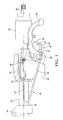
- Figure 1 is a side view of a steering column assembly
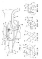
- Figure 2 is a cross-sectional side view of the steering column assembly illustrating a friction member, a jacket, a support bracket, a biasing member and a locking mechanism;
- Figure 3A is a top perspective view of the friction member
- Figure 3B is a side perspective view of the friction member
- Figure 3C is a top perspective view of the friction member and a portion of the biasing device
- Figure 3D is a front perspective view of the friction member and the portion of the biasing device
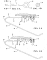
- Figure 4A is a planar side view of a fixed end of the biasing device
- Figure 4B is a cross-sectional view taken along line 4B-4B of Figure 4A ;
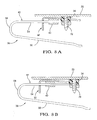
- Figure 5A is a fragmented partial cross-section of the support bracket, biasing device and friction member relative to the vehicle and a mounting component prior to a collision event;
- Figure 5B is a fragmented partial cross-section of the support bracket, biasing device and friction member relative to the vehicle and the mounting component after or during the collision event;
- Figure 6A is the planar side-view of an alternative embodiment of the friction member
- Figure 6B is a cross-sectional view taken along line 6B-6B in Figure 6A ;
- Figure 6C is a cross-sectional view taken along line 6C-6C in Figure 6A ;
- Figure 7A is a planar side view of an alternative embodiment of the biasing device
- Figure 7B is the cross-sectional view taken along line 7B-7B in Figure 7A ;
- Figure 7C is a cross-sectional view taken along line 7C-7C in Figure 7A ;
- Figure 8A is a fragmented partial cross-section of the support bracket, and alternative embodiments of the biasing device and friction member relative to the vehicle and the mounting component prior to a collision event;
- Figure 8B is a fragmented partial cross-section of the support bracket, and alternative embodiments of the biasing device and friction member relative to the vehicle and the mounting component after or during the collision event.
- a collapsible steering column assembly is shown generally at 20 in Figures 1-2 .
- the collapsible steering column assembly 20 includes a steering column 22 having a shaft 24 which extends into an operator compartment of a vehicle for accepting a steering wheel (not shown).
- the steering column 22 has a jacket 26 movable along a longitudinal axis 28 corresponding to a collapsing movement initiated by a collision event.
- the jacket 26 is also movable along the longitudinal axis 28 corresponding to telescoping movement and is movable about a pivot axis 30 corresponding to tilting movement between an upper limit and a lower limit, enabling an operator to adjust the steering column 22 during the normal course of operation of the vehicle.
- the jacket 26 is generally cylindrical, having a length extending along the longitudinal axis 28.
- the jacket 26 is mounted to a carriage bracket 46 which has a pair of sides 47 and a base 50, generally defining a channel 51.
- the jacket 26 is mounted to the sides 47, and is partially disposed within the channel 51.
- a support bracket 32 is provided for supporting the jacket 26 during the movements.
- the support bracket 32 is coupled to the jacket 26 and is movable with the jacket 26 during the collapsing movement.
- the support bracket 32 is generally disposed about the jacket 26 and includes a pair of walls 44 disposed on opposite sides of the jacket 26.
- the support bracket 32 further includes a platform 33 extending outwardly from each of the walls 44 in opposite directions relative to the jacket 26.
- the carriage bracket 46 is generally disposed between the walls 44 of the support bracket 32, with the carriage bracket 46 being movable with the jacket 26 during the movements.
- a mounting component 34 is connected to the vehicle 25 and the support bracket 32 is detachably coupled to the mounting component 34.
- the mounting component 34 includes a stud 78 mounted to the vehicle 25.
- the support bracket 32 remains stationary relative to the vehicle 25 during the telescoping and tilting movements.
- the stud 78 can be any suitable shape and mounted to the vehicle 25 in any suitable manner.
- the mounting component further includes a capsule 80 coupled to the stud 78 and to the platform 33 of the support bracket 32.
- a force in excess of a predetermined level is applied to the support bracket 32, as during a collision event, the capsule 80 releases the support bracket 32 which detaches from the stud 78 so that the support bracket 32 can move along the longitudinal axis 28 during the collapsing movement.
- Capsules 80 that release support brackets 32 for detachment from the vehicle 25 are well known in the art and are not the subj ect of the present invention.
- the capsule 80 can be constructed in any suitable manner, for instance, a plurality of pins can be disposed within the capsule 80 that shear upon a predetermined level of force to allow a portion of the capsule 80 to break away from the rest of the capsule 80.
- a locking mechanism 48 includes a lock bolt 52 which extends generally transverse to the longitudinal axis 28, and passes through the walls 44 of the support bracket 32 and the sides 47 of the carriage bracket 46 to couple the support bracket 32 to the carriage bracket 46 and the jacket 26.
- the locking mechanism 48 includes a handle 53 for allowing the operator to engage the locking mechanism 48 for preventing the movements of the jacket 26 and to disengage the locking mechanism 48 for allowing the tilting and the telescoping movements of the jacket 26.
- the locking mechanism 48 is movable with the support bracket 32 and the jacket 26 during the collapsing movement.
- the coupling of the jacket 26 to the support bracket 32 and the locking mechanism 48 have been only generally treated because they are not the subject of this invention. It can be readily appreciated that the coupling of the jacket 26 to the support bracket 32 and the locking mechanism 48 can be accomplished in any suitable manner.
- a biasing device 36 is coupled to the jacket 26 for urging the jacket 26 toward the upper limit.
- the biasing device 36 includes a fixed end 38 for fixedly coupling the biasing device 36 to the vehicle 25 during all of the movements.
- the biasing device 36 is generally wire-like having a generally circular cross-section and defining a thickness. It can be appreciated that other cross-sectional shapes such as an ellipse or rectangle are possible. Similarly, a variety of thicknesses are possible depending on the requirements of the specific application. In addition, the shapes and the thickness of the biasing device 36 can vary throughout the biasing device 36.
- the biasing device 36 includes a fixed end 38 for fixedly coupling the biasing device 36 to the vehicle 25.
- the fixed end can be any number of shapes and can be fixedly coupled to the vehicle 25 in any suitable manner.
- the fixed end 38 can include an eye 39 for engaging the stud 78 of the mounting component 34.
- the portion 42 of the biasing device 36 that engages the friction member 40 is further defined as a fixed arm 54.
- the fixed arm 54 extends generally along the longitudinal axis 28.
- the fixed arm 54 is substantially straight along a length to facilitate a uniform friction force when the friction member 40 slides along the fixed arm 54 to provide a predictable rate of energy absorption by the fixed arm 54.
- the fixed arm 54 is generally rigid. It can be readily appreciated that manufacturing, design and performance constraints can require that the fixed arm 54 incorporate a variety of shapes. For example, a slight bend 37 can be used to facilitate insertion of the fixed arm 54 into the friction member 40 during manufacturing. As discussed previously, the reason that the length is substantially straight is to facilitate a uniform friction force when the friction member 40 slides along the fixed arm 54. It can be readily appreciated that the portions of the fixed arm 54 which the friction member 40 does not slide along during the collapsing movement, can be any shape which allows the biasing device 36 to meet performance requirements of a specific application.
- the biasing device 36 includes a rake arm 56 for urging the jacket 26 toward the upper limit.
- the rake arm 56 is substantially straight along a length though it can be appreciated that the rake arm 56 could have other shapes such as being curved.
- the rake arm 56 is connected to the fixed arm 54 by a living hinge 58.
- the living hinge 58 is continuous and integral with the fixed arm 54 and the rake arm 56.
- the living hinge 58 generally defines an acute angle however the specific degree of the angle can vary depending on the requirements of the application.
- the rake arm 56 engages the locking mechanism 48 and urges the jacket 26 toward the upper limit during the tilting movement. During the collapsing movement, the rake arm 56 preferably detaches from the locking mechanism 48.
- the rake arm 56 can be engaged to the locking mechanism 48 in any suitable manner.
- the rake arm 56 can slide into a groove in the locking mechanism 48 or the rake arm 56 can include a contour that cooperates with a similar contour in the locking mechanism 48.
- a friction member 40 is mounted to the support bracket 32 and is movable with the support bracket 32.
- the friction member 40 engages the fixed arm 54 of the biasing device 36 forming a friction-fit.
- the support bracket 32 and friction member 40 move with the jacket 26 along the longitudinal axis 28.
- the friction member 40 slides along the fixed arm 54 of the biasing device 36, and because the fixed arm 54 remains coupled to the vehicle 25 by the fixed end 38, energy from the jacket 26 and support bracket 32 are transferred to the fixed arm 54 of the biasing device 36.
- the friction member 40 includes first and second ends 60, 62 with a plurality of legs 64, 66, 68 interconnected between the ends 60, 62.
- the friction member 40 includes a first leg 64, a second leg 66 and a third leg 68.
- the first leg 64 extends from the first end 60 and is connected to the second leg 66 by a first curved section 70.
- the third leg 68 extends from the second end 62 and is connected to the second leg 66 by a second curved section 72.
- the friction member 40 at least partially encircles the fixed arm 54, forming a friction-fit with the fixed arm 54, and slides along the fixed arm 54 during the collapsing movement for transferring energy from the jacket 26 and the support bracket 32 to the fixed arm 54.
- the legs 64, 66, 68 at least partially encircle the fixed arm 54.
- the legs 64, 66, 68 can have a variety of cross-sectional shapes, for example, circular or square.
- the first, second and third legs 64, 66, 68 are in spaced and substantially parallel relationship with each other with the legs 64, 66, 68 extending transverse to the longitudinal axis 28.
- the friction member 40 can be manufactured in a number of ways.
- the friction member 40 can be formed from a single unitary post or a plurality of posts joined by a process such as welding.
- the friction member 40 is mounted to the platform 33 of the support bracket 32 by the first and third legs 64, 68.
- the mounting of the legs 64, 68 on the platform 33 of the support bracket 32 can be accomplished by in any reasonable manner, for example, the legs 64, 68 can include projections 73 which are welded to the platform 33.
- the platform 33 can include a plurality of ribs 71 for mounting the legs 64, 68 to the platform 33.
- the friction member 40 can include any number of legs 64, 66, 68 and curved sections 70, 72 and the orientation of the legs 64, 66, 68 to each other and in relation to the longitudinal axis 28 can vary depending on the materials used and the amount of energy absorption required by a specific application.
- the friction member 40 includes an inner surface 74 which defines a passageway 76 and the inner surface 74 engages the fixed arm 54. Because the legs 64, 66, 68 are in spaced relationship with each other, the inner surface 74 of the friction member 40 is discontinuous, having open spaces where there is no contact between the fixed arm 54 and the friction member 40.
- the passageway 76 has a height and width which can vary within the passageway 76, and as a result, the passageway 76 can have a variety of shapes. For example, force can be applied to the second leg 66 during the mounting of the friction member 40 to the platform 33 which will produce a slightly curved passageway 76. The resulting restriction in the passageway 76 makes the friction-fit tighter and the friction created as the friction member 40 slides along the generally rigid fixed arm 54 is increased.
- the friction-fit between the fixed arm 54 and the friction member 40 allows the transfer of energy from the jacket 26 and the support bracket 32 to the fixed arm 54. If the friction-fit is too tight or the shape of the passageway 76 too restrictive, the fixed arm 54 will not be able to slide adequately during the collapsing movement. Conversely, if the friction-fit is too loose, the friction member 40 will be allowed to move too easily along the fixed arm 54 and not enough resistance will be created to effect the transfer of energy from the jacket and support bracket. It can be readily appreciated that the thickness, width, height and shape of the passageway 76 and the fixed arm 54 can vary in order to achieve the friction-fit required for a given application.
- the operator can select a position for the steering wheel by adjusting the position of the jacket 26 using one or both of the tilting and telescoping movements discussed previously.
- the telescoping movement occurs when the jacket 26 moves along the longitudinal axis 28.
- the pivoting movement occurs when the jacket 26 moves about the pivot axis 30.
- the operator uses the handle 53 to disengage the locking mechanism 48 as previously discussed.
- the jacket 26 which is movably coupled to the support bracket 32 moves along the longitudinal axis 28 for the telescoping movement and about the pivot axis 30 between the upper and lower limit for the tilting movement.
- the support bracket 32 and the fixed arm 54, both of which are coupled to the vehicle 25, do not move.
- the operator uses the handle 53 to engage the locking mechanism 48 as previously discussed, to retain the jacket 26 in the selected position.
- the friction member 40 slides in a substantially straight path along the fixed arm 54, and as a result of the friction-fit, energy is transferred from the jacket 26 and the support bracket 32 to the fixed arm 54 and the rate of travel of the jacket 26 and support bracket 32 along the longitudinal axis 28 is reduced.
- FIGS 5A-5B the change in positions of the support bracket 32, friction member 40, mounting component 34 and fixed arm 54 relative to the vehicle 25 is illustrated.
- the support bracket 32 prior to the collision event, is coupled to the mounting component 34.
- Figure 5B illustrates the change after the collision event.
- the support bracket 32 has released from the capsule 80 of the mounting component 34 detaching from the stud 78 connected to the vehicle 25 and has moved along the longitudinal axis 28.
- the fixed arm 54 has remained connected to the vehicle 25, in this case shown as remaining connected to the stud 78.
- the friction member 40 has moved with the support bracket 32, sliding along the length of the fixed arm 54.
- the friction member 40 slides along a relatively straight path, however it is possible that some distortion of the biasing device 36 can occur, depending on configuration, materials used and magnitude of force exerted on the steering column 22.
- the inner surface 74 is continuous along a length, and substantially encapsulates the fixed arm 54. Because the inner surface 74 is continuous, the height and the width of the passageway 76 further define a cross-sectional area.
- the passageway 76 is further defined as a first zone 82 having a first cross-sectional area C 1 and a second zone 84 having a second cross-sectional C 2 area smaller than the first cross-sectional area C 1 of the first zone 82.
- the passageway 76 further includes a tapered zone 86 connecting the first zone 82 and the second zone 84.
- the fixed arm 54 includes a first section 88 defining a first thickness T 1 complementary in configuration to the first zone 82, a tapered section 92 complementary in configuration to the tapered zone 86, and a second section 90 with a second thickness T 2 complementary in configuration to the second zone 84.
- the inner surface 74 defining the tapered zone 86 presses against the first section 88 of the fixed arm 54 as the friction member 40 slides along the fixed arm 54.
- the first section 88 of the fixed arm 54 is forced through a decreasing cross-sectional area, and as a result, the first section 88 of the fixed arm 54 is extruded and lengthened.
- the cross-sectional areas of the zones 82, 84, 86 can vary depending upon the requirements of a specific application.
- the zones 82, 84, 86 can have a variety of cross-sectional shapes, for example, circular or D-shaped.
- FIGS. 8A-8B the change in the positions of the support bracket 32, friction member 40, mounting component 34 and fixed arm 54 relative to the vehicle 25 is illustrated.
- the support bracket 32 prior to the collision event, the support bracket 32 is coupled to the mounting component 34.
- the collapsing movement of the steering column 22 is very similar to the collapsing movement described in the preferred embodiment. Once the collapsing movement commences, however, the friction member 40 and fixed arm 54 interact differently to effect the transfer of energy from the jacket and support bracket 32 to the fixed arm 54.
- the support bracket 32 releases from capsule of the mounting component 34 and detaches from the stud 78 connected to the vehicle 25 while the fixed arm 54 remains connected to the vehicle 25.
- the friction member 40 begins to slide along the fixed arm 54, however, the friction member 40 operates as an extrusion die.
- the fixed arm 54 is forced from the first zone 82 having the larger cross-sectional area C 1 through the tapered zone 86 into the second zone 84 having the smaller cross-sectional area C 2 .
- Figure 8B illustrates the change after the collision event.
- the support bracket 32 which has released from the mounting component 34 has moved along the longitudinal axis 28.
- the fixed arm 54 has remained connected to the vehicle 25, in this case shown as remaining connected to the stud 78.
- the friction member 40 has moved with the support bracket 32, sliding along the fixed arm 54.
- the fixed arm 54 has been lengthened as a result of the extrusion.
Landscapes
- Engineering & Computer Science (AREA)
- Chemical & Material Sciences (AREA)
- Combustion & Propulsion (AREA)
- Transportation (AREA)
- Mechanical Engineering (AREA)
- Steering Controls (AREA)
- Vibration Dampers (AREA)
Claims (17)
- Zusammenschiebbare Lenksäulenanordnung für ein Fahrzeug, wobei die Anordnung (20) umfasst:eine Lenksäule (22) mit einer Ummantelung (26), die entlang einer Längsachse (28) für eine Teleskopbewegung und eine zusammenschiebende Bewegung bewegbar ist und wobei die Ummantelung (26) um eine Drehachse (30) für eine Kippbewegung zwischen einer oberen Grenze und einer unteren Grenze bewegbar ist;eine Lagerhalterung (32), die mit der Ummantelung (26) zum Lagern der Ummantelung (26) während der Bewegungen gekoppelt ist undmit der Ummantelung (26) während der zusammenschiebenden Bewegung bewegbar ist;ein Reibungselement (40), das an der Lagerhalterung (32) montiert ist;eine Vorspannvorrichtung (36), die mit der Ummantelung (26) gekoppelt ist, um die Ummantelung (26) in Richtung der oberen Grenze zu treiben; undwobei das Reibungselement (40) mit einem Abschnitt (42) der Vorspannvorrichtung (36) in Eingriff steht und entlang der Vorspannvorrichtung (36) während der zusammenschiebenden Bewegung zur Übertragung von Energie von der Ummantelung (26) und der Lagerhalterung (32) zu der Vorspannvorrichtung (36) gleitet;dadurch gekennzeichnet, dass das Reibungselement (40) mit der Lagerhalterung (32) entlang der Längsachse (28) während der zusammenschiebenden Bewegung bewegbar ist,dass das Reibungselement (40) eine Innenfläche aufweist, die einen Durchgang (76) definiert, wobei die Innenfläche mit dem Abschnitt (42) der Vorspannvorrichtung (36) in Eingriff steht,dass der Abschnitt (42) der Vorspannvorrichtung (36) eine Dicke besitzt und der Durchgang (76) eine Höhe und eine Breite besitzt, wobei die Höhe und/oder die Breite identisch zu der Dicke der Vorspannvorrichtung (36) ist/ sind, um eine Reibpassung zwischen dem Reibungselement (40) und der Vorspannvorrichtung (36) zu bilden,und dass das Reibungselement (40) den Abschnitt (42) der Vorspannvorrichtung (36) zumindest teilweise umgibt.
- Anordnung nach Anspruch 1,
wobei der Abschnitt (42) der Vorspannvorrichtung (36) ferner als ein fixierter Arm (54) definiert ist, der mit dem Reibungselement (40) in Eingriff steht, wobei der fixierte Arm (54) entlang einer Länge im Wesentlichen gerade ist, um eine gleichförmige Reibungskraft zu unterstützen, wenn das Reibungselement (40) entlang der Vorspannvorrichtung (36) gleitet. - Anordnung nach Anspruch 2,
wobei die Vorspannvorrichtung (36) ferner einen Stellarm (56) und ein Gelenk (58) aufweist, wobei das Gelenk (58) den fixierten Arm (54) und den Stellarm (56) verbindet und der Stellarm (56) die Ummantelung (26) in Richtung der oberen Grenze treibt. - Anordnung nach Anspruch 3,
wobei die Vorspannvorrichtung (36) im Wesentlichen drahtartig mit einem allgemein kreisförmigen Querschnitt ist. - Anordnung nach Anspruch 1,
wobei die Vorspannvorrichtung (36) ein fixiertes Ende (38) zur fixierten Kopplung der Vorspannvorrichtung (36) mit dem Fahrzeug umfasst, um eine Bewegung der Vorspannvorrichtung (36) entlang der Längsachse (28) während der zusammenschiebenden Bewegung der Lagerhalterung (32) und der Ummantelung (26) zu verhindern. - Anordnung nach Anspruch 1,
mit einer Montagekomponente (34), die mit der Lagerhalterung (32) gekoppelt ist, um die Lagerhalterung (32) lösbar mit dem Fahrzeug zu koppeln. - Anordnung nach Anspruch 6,
wobei die Montagekomponente (34) einen Bolzen (78) zur Verbindung der Montagekomponente (34) mit dem Fahrzeug und eine Kapsel aufweist, die mit der Lagerhalterung (32) in Eingriff steht und die Lagerhalterung (32) mit dem Zapfen (78) während der Teleskopbewegung und der Kippbewegung koppelt und ermöglicht, dass die Lagerhalterung (32) von dem Bolzen (78) ausrücken kann, wenn eine Kraft auf die Ummantelung (26) ausgeübt wird, die ein vorbestimmtes Niveau überschreitet, um die zusammenschiebende Bewegung zu ermöglichen. - Anordnung nach Anspruch 1,
wobei das Reibungselement (40) ein erstes und zweites Ende (60, 62) mit einer Mehrzahl von Schenkeln (64, 66, 68) aufweist, die zwischen den Enden (60, 62) verbunden sind, und die Schenkel (64, 66, 68) den Abschnitt (42) der Vorspannvorrichtung (36) zumindest teilweise umgeben. - Anordnung nach Anspruch 8,
wobei die Mehrzahl von Schenkeln einen ersten Schenkel (64) und einen zweiten Schenkel (66) aufweist, wobei ein erstes gekrümmtes Teil (70) den ersten Schenkel (64) mit dem zweiten Schenkel (66) verbindet, und einen dritten Schenkel (68) aufweist, wobei ein zweites gekrümmtes Teil (72) den zweiten Schenkel (66) mit dem dritten Schenkel (68) verbindet. - Anordnung nach Anspruch 9,
wobei der erste, zweite und dritte Schenkel (64, 66, 68) beabstandet und in im Wesentlichen paralleler Beziehung zueinander angeordnet sind und sich quer zu der Längsachse (28) erstrecken. - Anordnung nach Anspruch 9,
wobei der erste Schenkel (64) und der dritte Schenkel (68) an der Lagerhalterung (32) montiert sind. - Anordnung nach Anspruch 1,
wobei die Innenfläche entlang einer Länge kontinuierlich ist und den Abschnitt (42) der Vorspannvorrichtung (36) im Wesentlichen einkapselt. - Anordnung nach Anspruch 12,
wobei der Abschnitt (42) der Vorspannvorrichtung (36) ferner als ein fixierter Arm (54) definiert ist, wobei die Dicke des fixierten Armes (54) in der Konfiguration komplementär zu der Höhe und der Breite des Durchganges (76) ist. - Anordnung nach Anspruch 13,
wobei der Durchgang (76) eine erste Zone (82), die eine erste Querschnittsfläche (C1) definiert, und eine zweite Zone (84) aufweist, die eine zweite Querschnittsfläche (C2) definiert, die kleiner als die erste Querschnittsfläche der ersten Zone (82) ist. - Anordnung nach Anspruch 14,
wobei der fixierte Arm (54) ein erstes Teil (88), das in der Konfiguration komplementär zu der ersten Zone (82) ist, und ein zweites Teil (90) aufweist, das in der Konfiguration komplementär zu der zweiten Zone (84) ist. - Anordnung nach Anspruch 15,
wobei der Durchgang (76) ferner eine verjüngte Zone (86) aufweist, die die erste Zone (82) mit der zweiten Zone (84) verbindet. - Anordnung nach Anspruch 16,
wobei der fixierte Arm (54) ein verjüngtes Teil (92) aufweist, das in der Konfiguration komplementär zu der verjüngten Zone (86) ist.
Applications Claiming Priority (1)
| Application Number | Priority Date | Filing Date | Title |
|---|---|---|---|
| US11/543,564 US7780196B2 (en) | 2006-10-05 | 2006-10-05 | Energy absorbing steering column assembly |
Publications (3)
| Publication Number | Publication Date |
|---|---|
| EP1908663A2 EP1908663A2 (de) | 2008-04-09 |
| EP1908663A3 EP1908663A3 (de) | 2009-04-15 |
| EP1908663B1 true EP1908663B1 (de) | 2010-12-01 |
Family
ID=38875033
Family Applications (1)
| Application Number | Title | Priority Date | Filing Date |
|---|---|---|---|
| EP07117564A Not-in-force EP1908663B1 (de) | 2006-10-05 | 2007-09-28 | Energieabsorbierende Lenksäulenanordnung |
Country Status (4)
| Country | Link |
|---|---|
| US (1) | US7780196B2 (de) |
| EP (1) | EP1908663B1 (de) |
| AT (1) | ATE490148T1 (de) |
| DE (1) | DE602007010877D1 (de) |
Families Citing this family (15)
| Publication number | Priority date | Publication date | Assignee | Title |
|---|---|---|---|---|
| US8033574B2 (en) * | 2006-11-15 | 2011-10-11 | Nexteer (Beijing) Technology Co., Ltd. | Collapsible steering column assembly |
| KR100848497B1 (ko) * | 2007-01-19 | 2008-07-28 | 주식회사 만도 | 와이어 블록 어셈블리를 구비한 자동차의 충격 흡수식조향컬럼 |
| GB2451506B (en) * | 2007-08-02 | 2011-12-28 | Ford Global Tech Llc | An adjustable steering column assembly for a motor vehicle |
| DE102007048208B4 (de) * | 2007-10-08 | 2009-07-09 | Thyssenkrupp Presta Ag | Lenksäule für ein Kraftfahrzeug |
| GB0816354D0 (en) * | 2008-09-06 | 2008-10-15 | Trw Ltd | Steering column assembly |
| CN102009684B (zh) * | 2009-05-29 | 2013-06-19 | 通用汽车环球科技运作公司 | 用于可折叠转向柱组件的能量吸收装置 |
| US8955881B2 (en) * | 2011-05-13 | 2015-02-17 | Steering Solutions Ip Holding Corporation | Telescoping steering column having rake spring |
| US8702126B2 (en) | 2012-02-15 | 2014-04-22 | Ford Global Technologies, Llc | Device for secondary energy management in a steering column assembly |
| JP5408367B1 (ja) * | 2012-03-06 | 2014-02-05 | 日本精工株式会社 | 衝撃吸収式ステアリング装置 |
| JP2014040181A (ja) | 2012-08-22 | 2014-03-06 | Jtekt Corp | ステアリング装置 |
| JP2015009685A (ja) * | 2013-06-28 | 2015-01-19 | 株式会社ジェイテクト | ステアリング装置 |
| JP6990349B2 (ja) * | 2017-02-07 | 2022-01-12 | 株式会社ジェイテクト | ステアリング装置 |
| GB2575885B (en) * | 2018-07-25 | 2022-07-13 | Trw Steering Systems Poland Sp Z O O | A steering column assembly |
| GB2612383B (en) * | 2021-10-27 | 2025-03-26 | Zf Steering Systems Poland Sp Z O O | Steering column assembly |
| US12606231B1 (en) * | 2025-03-28 | 2026-04-21 | Steering Solutions Ip Holding Corporation | Collapsible steering column assembly with releasably attached spring |
Family Cites Families (24)
| Publication number | Priority date | Publication date | Assignee | Title |
|---|---|---|---|---|
| GB2291840A (en) | 1994-07-29 | 1996-02-07 | Torrington Co | Vehicle steering column reach adjustment and energy absorbing mechanism |
| US5487562A (en) | 1994-12-27 | 1996-01-30 | Ford Motor Company | Energy absorbing apparatus for a motor vehicle |
| US5961146A (en) * | 1996-01-18 | 1999-10-05 | Nsk Ltd. | Shock absorbing type steering column assembly |
| SE507771C2 (sv) * | 1996-11-21 | 1998-07-13 | Volvo Ab | Anordning och förfarande för skydd av åkande i fordon |
| JP3612971B2 (ja) | 1997-12-03 | 2005-01-26 | 日本精工株式会社 | 衝撃吸収式ステアリングコラム装置 |
| US6189405B1 (en) * | 1998-04-30 | 2001-02-20 | Kabushiki Kaisha Yamada Seisa Kusho | Position adjusting device for steering wheels |
| GB2344078B (en) | 1998-11-24 | 2002-03-13 | Nastech Europ Ltd | Collapsible steering column for a vehicle |
| EP1192072B1 (de) * | 1999-06-11 | 2003-11-26 | Delphi Technologies, Inc. | Energieaufnehmer für kraftfahrzeuglenksäule |
| US6419269B1 (en) * | 1999-09-20 | 2002-07-16 | Delphi Technologies | Locking system for adjustable position steering column |
| US6726248B2 (en) * | 2000-05-16 | 2004-04-27 | Nsk Ltd. | Impact absorbing type steering column apparatus |
| JP3431886B2 (ja) * | 2000-07-07 | 2003-07-28 | 株式会社山田製作所 | ステアリング位置調整装置 |
| US6659504B2 (en) * | 2001-05-18 | 2003-12-09 | Delphi Technologies, Inc. | Steering column for a vehicle |
| JP3895566B2 (ja) * | 2001-08-07 | 2007-03-22 | 本田技研工業株式会社 | 車両用ステアリング装置 |
| US6655716B2 (en) * | 2001-08-28 | 2003-12-02 | Delphi Technologies, Inc. | Kinetic energy absorber |
| US6652002B2 (en) * | 2001-10-19 | 2003-11-25 | Delphi Technologies, Inc. | Crash responsive energy absorbing device for a steering column |
| WO2003035431A2 (en) | 2001-10-19 | 2003-05-01 | Delphi Technologies Inc. | Responsive energy absorbing device for a steering column |
| DE60223590T2 (de) * | 2001-11-30 | 2008-09-18 | Delphi Technologies, Inc., Troy | Reaktionsenergieaufnahmesystem |
| JP4147579B2 (ja) * | 2002-01-17 | 2008-09-10 | 日本精工株式会社 | ステアリング装置 |
| EP1504980A4 (de) * | 2002-05-10 | 2006-04-26 | Nsk Ltd | Lenkvorrichtung |
| JP4134601B2 (ja) * | 2002-06-04 | 2008-08-20 | 日本精工株式会社 | 車両用チルト式ステアリングコラム装置 |
| JP3945706B2 (ja) * | 2002-07-31 | 2007-07-18 | 株式会社山田製作所 | ステアリングハンドルの位置調整装置 |
| US7325833B2 (en) * | 2002-11-11 | 2008-02-05 | Nsk Ltd. | Steering device for motor vehicle |
| DE602004021364D1 (de) * | 2003-03-26 | 2009-07-16 | Nsk Ltd | Lenkvorrichtung für ein kraftfahrzeug |
| FR2857322B1 (fr) | 2003-07-10 | 2006-08-11 | Nacam | Dispositif d'absorption d'energie infiniment modulable d'une colonne de direction de vehicule automobile |
-
2006
- 2006-10-05 US US11/543,564 patent/US7780196B2/en not_active Expired - Fee Related
-
2007
- 2007-09-28 AT AT07117564T patent/ATE490148T1/de not_active IP Right Cessation
- 2007-09-28 EP EP07117564A patent/EP1908663B1/de not_active Not-in-force
- 2007-09-28 DE DE602007010877T patent/DE602007010877D1/de active Active
Also Published As
| Publication number | Publication date |
|---|---|
| US20080084055A1 (en) | 2008-04-10 |
| US7780196B2 (en) | 2010-08-24 |
| EP1908663A3 (de) | 2009-04-15 |
| DE602007010877D1 (de) | 2011-01-13 |
| EP1908663A2 (de) | 2008-04-09 |
| ATE490148T1 (de) | 2010-12-15 |
Similar Documents
| Publication | Publication Date | Title |
|---|---|---|
| EP1908663B1 (de) | Energieabsorbierende Lenksäulenanordnung | |
| US6659504B2 (en) | Steering column for a vehicle | |
| US8366149B2 (en) | Steering column for a motor vehicle | |
| EP2535239B1 (de) | Lenkvorrichtung | |
| US8474869B2 (en) | Steering column for a motor vehicle | |
| US8979128B2 (en) | Collapsible steering column assembly | |
| EP2636573B1 (de) | Lenksäulenhilfsvorrichtung | |
| US5286056A (en) | Device for absorbing energy transmitted through a vehicle steering column | |
| JP6518099B2 (ja) | ステアリング装置 | |
| US8632098B2 (en) | Improvements relating to steering assemblies | |
| EP2923919A1 (de) | Lenkvorrichtung | |
| JP5720813B2 (ja) | 衝撃吸収式ステアリング装置 | |
| WO2008050639A1 (en) | Position adjusting device for steering wheel | |
| CN102712332A (zh) | 转向柱用支承装置 | |
| JP2014076804A5 (de) | ||
| JPH0575057U (ja) | 衝撃吸収式ステアリングコラム装置 | |
| JPH082026Y2 (ja) | 衝撃吸収式ステアリングコラム装置 | |
| US9682720B2 (en) | Steering column assembly | |
| US7255369B2 (en) | Shock absorption type steering column device | |
| JP2001260902A (ja) | 衝撃吸収式ステアリング装置 | |
| JPH08295251A (ja) | 衝撃吸収式ステアリングコラム装置 | |
| EP3439942B1 (de) | Lenksäulenanordnung | |
| US7124866B2 (en) | Adaptive energy absorber | |
| DE102021200946B4 (de) | Lenksäule für ein Kraftfahrzeug | |
| JPH09193813A (ja) | エネルギー吸収式ステアリング装置 |
Legal Events
| Date | Code | Title | Description |
|---|---|---|---|
| PUAI | Public reference made under article 153(3) epc to a published international application that has entered the european phase |
Free format text: ORIGINAL CODE: 0009012 |
|
| AK | Designated contracting states |
Kind code of ref document: A2 Designated state(s): AT BE BG CH CY CZ DE DK EE ES FI FR GB GR HU IE IS IT LI LT LU LV MC MT NL PL PT RO SE SI SK TR |
|
| AX | Request for extension of the european patent |
Extension state: AL BA HR MK RS |
|
| PUAL | Search report despatched |
Free format text: ORIGINAL CODE: 0009013 |
|
| AK | Designated contracting states |
Kind code of ref document: A3 Designated state(s): AT BE BG CH CY CZ DE DK EE ES FI FR GB GR HU IE IS IT LI LT LU LV MC MT NL PL PT RO SE SI SK TR |
|
| AX | Request for extension of the european patent |
Extension state: AL BA HR MK RS |
|
| 17P | Request for examination filed |
Effective date: 20090909 |
|
| 17Q | First examination report despatched |
Effective date: 20091023 |
|
| AKX | Designation fees paid |
Designated state(s): AT BE BG CH CY CZ DE DK EE ES FI FR GB GR HU IE IS IT LI LT LU LV MC MT NL PL PT RO SE SI SK TR |
|
| GRAP | Despatch of communication of intention to grant a patent |
Free format text: ORIGINAL CODE: EPIDOSNIGR1 |
|
| GRAS | Grant fee paid |
Free format text: ORIGINAL CODE: EPIDOSNIGR3 |
|
| GRAA | (expected) grant |
Free format text: ORIGINAL CODE: 0009210 |
|
| AK | Designated contracting states |
Kind code of ref document: B1 Designated state(s): AT BE BG CH CY CZ DE DK EE ES FI FR GB GR HU IE IS IT LI LT LU LV MC MT NL PL PT RO SE SI SK TR |
|
| REG | Reference to a national code |
Ref country code: GB Ref legal event code: FG4D |
|
| REG | Reference to a national code |
Ref country code: CH Ref legal event code: EP |
|
| REG | Reference to a national code |
Ref country code: IE Ref legal event code: FG4D |
|
| RAP2 | Party data changed (patent owner data changed or rights of a patent transferred) |
Owner name: GM GLOBAL TECHNOLOGY OPERATIONS, INC. |
|
| REF | Corresponds to: |
Ref document number: 602007010877 Country of ref document: DE Date of ref document: 20110113 Kind code of ref document: P |
|
| REG | Reference to a national code |
Ref country code: NL Ref legal event code: VDEP Effective date: 20101201 |
|
| PG25 | Lapsed in a contracting state [announced via postgrant information from national office to epo] |
Ref country code: LT Free format text: LAPSE BECAUSE OF FAILURE TO SUBMIT A TRANSLATION OF THE DESCRIPTION OR TO PAY THE FEE WITHIN THE PRESCRIBED TIME-LIMIT Effective date: 20101201 |
|
| LTIE | Lt: invalidation of european patent or patent extension |
Effective date: 20101201 |
|
| PG25 | Lapsed in a contracting state [announced via postgrant information from national office to epo] |
Ref country code: CY Free format text: LAPSE BECAUSE OF FAILURE TO SUBMIT A TRANSLATION OF THE DESCRIPTION OR TO PAY THE FEE WITHIN THE PRESCRIBED TIME-LIMIT Effective date: 20101201 Ref country code: AT Free format text: LAPSE BECAUSE OF FAILURE TO SUBMIT A TRANSLATION OF THE DESCRIPTION OR TO PAY THE FEE WITHIN THE PRESCRIBED TIME-LIMIT Effective date: 20101201 Ref country code: FI Free format text: LAPSE BECAUSE OF FAILURE TO SUBMIT A TRANSLATION OF THE DESCRIPTION OR TO PAY THE FEE WITHIN THE PRESCRIBED TIME-LIMIT Effective date: 20101201 Ref country code: SI Free format text: LAPSE BECAUSE OF FAILURE TO SUBMIT A TRANSLATION OF THE DESCRIPTION OR TO PAY THE FEE WITHIN THE PRESCRIBED TIME-LIMIT Effective date: 20101201 Ref country code: SE Free format text: LAPSE BECAUSE OF FAILURE TO SUBMIT A TRANSLATION OF THE DESCRIPTION OR TO PAY THE FEE WITHIN THE PRESCRIBED TIME-LIMIT Effective date: 20101201 Ref country code: BG Free format text: LAPSE BECAUSE OF FAILURE TO SUBMIT A TRANSLATION OF THE DESCRIPTION OR TO PAY THE FEE WITHIN THE PRESCRIBED TIME-LIMIT Effective date: 20110301 Ref country code: LV Free format text: LAPSE BECAUSE OF FAILURE TO SUBMIT A TRANSLATION OF THE DESCRIPTION OR TO PAY THE FEE WITHIN THE PRESCRIBED TIME-LIMIT Effective date: 20101201 Ref country code: NL Free format text: LAPSE BECAUSE OF FAILURE TO SUBMIT A TRANSLATION OF THE DESCRIPTION OR TO PAY THE FEE WITHIN THE PRESCRIBED TIME-LIMIT Effective date: 20101201 |
|
| PG25 | Lapsed in a contracting state [announced via postgrant information from national office to epo] |
Ref country code: GR Free format text: LAPSE BECAUSE OF FAILURE TO SUBMIT A TRANSLATION OF THE DESCRIPTION OR TO PAY THE FEE WITHIN THE PRESCRIBED TIME-LIMIT Effective date: 20110302 |
|
| REG | Reference to a national code |
Ref country code: CH Ref legal event code: PFA Owner name: GM GLOBAL TECHNOLOGY OPERATIONS LLC Free format text: GM GLOBAL TECHNOLOGY OPERATIONS, INC.#300 RENAISSANCE CENTER MC 482-C23-B21#DETROIT, MI 48265-3000 (US) -TRANSFER TO- GM GLOBAL TECHNOLOGY OPERATIONS LLC#300 RENAISSANCE CENTER#DETROIT, MI 48265-3000 (US) |
|
| RAP2 | Party data changed (patent owner data changed or rights of a patent transferred) |
Owner name: GM GLOBAL TECHNOLOGY OPERATIONS LLC |
|
| PG25 | Lapsed in a contracting state [announced via postgrant information from national office to epo] |
Ref country code: CZ Free format text: LAPSE BECAUSE OF FAILURE TO SUBMIT A TRANSLATION OF THE DESCRIPTION OR TO PAY THE FEE WITHIN THE PRESCRIBED TIME-LIMIT Effective date: 20101201 Ref country code: EE Free format text: LAPSE BECAUSE OF FAILURE TO SUBMIT A TRANSLATION OF THE DESCRIPTION OR TO PAY THE FEE WITHIN THE PRESCRIBED TIME-LIMIT Effective date: 20101201 Ref country code: ES Free format text: LAPSE BECAUSE OF FAILURE TO SUBMIT A TRANSLATION OF THE DESCRIPTION OR TO PAY THE FEE WITHIN THE PRESCRIBED TIME-LIMIT Effective date: 20110312 Ref country code: BE Free format text: LAPSE BECAUSE OF FAILURE TO SUBMIT A TRANSLATION OF THE DESCRIPTION OR TO PAY THE FEE WITHIN THE PRESCRIBED TIME-LIMIT Effective date: 20101201 Ref country code: PT Free format text: LAPSE BECAUSE OF FAILURE TO SUBMIT A TRANSLATION OF THE DESCRIPTION OR TO PAY THE FEE WITHIN THE PRESCRIBED TIME-LIMIT Effective date: 20110401 Ref country code: IS Free format text: LAPSE BECAUSE OF FAILURE TO SUBMIT A TRANSLATION OF THE DESCRIPTION OR TO PAY THE FEE WITHIN THE PRESCRIBED TIME-LIMIT Effective date: 20110401 |
|
| PG25 | Lapsed in a contracting state [announced via postgrant information from national office to epo] |
Ref country code: SK Free format text: LAPSE BECAUSE OF FAILURE TO SUBMIT A TRANSLATION OF THE DESCRIPTION OR TO PAY THE FEE WITHIN THE PRESCRIBED TIME-LIMIT Effective date: 20101201 Ref country code: RO Free format text: LAPSE BECAUSE OF FAILURE TO SUBMIT A TRANSLATION OF THE DESCRIPTION OR TO PAY THE FEE WITHIN THE PRESCRIBED TIME-LIMIT Effective date: 20101201 Ref country code: PL Free format text: LAPSE BECAUSE OF FAILURE TO SUBMIT A TRANSLATION OF THE DESCRIPTION OR TO PAY THE FEE WITHIN THE PRESCRIBED TIME-LIMIT Effective date: 20101201 |
|
| PLBE | No opposition filed within time limit |
Free format text: ORIGINAL CODE: 0009261 |
|
| STAA | Information on the status of an ep patent application or granted ep patent |
Free format text: STATUS: NO OPPOSITION FILED WITHIN TIME LIMIT |
|
| PG25 | Lapsed in a contracting state [announced via postgrant information from national office to epo] |
Ref country code: DK Free format text: LAPSE BECAUSE OF FAILURE TO SUBMIT A TRANSLATION OF THE DESCRIPTION OR TO PAY THE FEE WITHIN THE PRESCRIBED TIME-LIMIT Effective date: 20101201 |
|
| 26N | No opposition filed |
Effective date: 20110902 |
|
| REG | Reference to a national code |
Ref country code: DE Ref legal event code: R097 Ref document number: 602007010877 Country of ref document: DE Effective date: 20110902 |
|
| PG25 | Lapsed in a contracting state [announced via postgrant information from national office to epo] |
Ref country code: IT Free format text: LAPSE BECAUSE OF FAILURE TO SUBMIT A TRANSLATION OF THE DESCRIPTION OR TO PAY THE FEE WITHIN THE PRESCRIBED TIME-LIMIT Effective date: 20101201 |
|
| PG25 | Lapsed in a contracting state [announced via postgrant information from national office to epo] |
Ref country code: MC Free format text: LAPSE BECAUSE OF NON-PAYMENT OF DUE FEES Effective date: 20110930 |
|
| REG | Reference to a national code |
Ref country code: CH Ref legal event code: PL |
|
| GBPC | Gb: european patent ceased through non-payment of renewal fee |
Effective date: 20110928 |
|
| REG | Reference to a national code |
Ref country code: IE Ref legal event code: MM4A |
|
| REG | Reference to a national code |
Ref country code: FR Ref legal event code: ST Effective date: 20120531 |
|
| PG25 | Lapsed in a contracting state [announced via postgrant information from national office to epo] |
Ref country code: CH Free format text: LAPSE BECAUSE OF NON-PAYMENT OF DUE FEES Effective date: 20110930 Ref country code: IE Free format text: LAPSE BECAUSE OF NON-PAYMENT OF DUE FEES Effective date: 20110928 Ref country code: LI Free format text: LAPSE BECAUSE OF NON-PAYMENT OF DUE FEES Effective date: 20110930 |
|
| PG25 | Lapsed in a contracting state [announced via postgrant information from national office to epo] |
Ref country code: GB Free format text: LAPSE BECAUSE OF NON-PAYMENT OF DUE FEES Effective date: 20110928 Ref country code: FR Free format text: LAPSE BECAUSE OF NON-PAYMENT OF DUE FEES Effective date: 20110930 |
|
| PGFP | Annual fee paid to national office [announced via postgrant information from national office to epo] |
Ref country code: DE Payment date: 20120927 Year of fee payment: 6 |
|
| PG25 | Lapsed in a contracting state [announced via postgrant information from national office to epo] |
Ref country code: MT Free format text: LAPSE BECAUSE OF FAILURE TO SUBMIT A TRANSLATION OF THE DESCRIPTION OR TO PAY THE FEE WITHIN THE PRESCRIBED TIME-LIMIT Effective date: 20101201 |
|
| PG25 | Lapsed in a contracting state [announced via postgrant information from national office to epo] |
Ref country code: LU Free format text: LAPSE BECAUSE OF NON-PAYMENT OF DUE FEES Effective date: 20110928 |
|
| PG25 | Lapsed in a contracting state [announced via postgrant information from national office to epo] |
Ref country code: TR Free format text: LAPSE BECAUSE OF FAILURE TO SUBMIT A TRANSLATION OF THE DESCRIPTION OR TO PAY THE FEE WITHIN THE PRESCRIBED TIME-LIMIT Effective date: 20101201 |
|
| PG25 | Lapsed in a contracting state [announced via postgrant information from national office to epo] |
Ref country code: HU Free format text: LAPSE BECAUSE OF FAILURE TO SUBMIT A TRANSLATION OF THE DESCRIPTION OR TO PAY THE FEE WITHIN THE PRESCRIBED TIME-LIMIT Effective date: 20101201 |
|
| REG | Reference to a national code |
Ref country code: DE Ref legal event code: R119 Ref document number: 602007010877 Country of ref document: DE Effective date: 20140401 |
|
| PG25 | Lapsed in a contracting state [announced via postgrant information from national office to epo] |
Ref country code: DE Free format text: LAPSE BECAUSE OF NON-PAYMENT OF DUE FEES Effective date: 20140401 |