EP1908651A1 - Seatbelt device - Google Patents
Seatbelt device Download PDFInfo
- Publication number
- EP1908651A1 EP1908651A1 EP06756882A EP06756882A EP1908651A1 EP 1908651 A1 EP1908651 A1 EP 1908651A1 EP 06756882 A EP06756882 A EP 06756882A EP 06756882 A EP06756882 A EP 06756882A EP 1908651 A1 EP1908651 A1 EP 1908651A1
- Authority
- EP
- European Patent Office
- Prior art keywords
- switch
- projecting portion
- gear
- webbing
- seat belt
- Prior art date
- Legal status (The legal status is an assumption and is not a legal conclusion. Google has not performed a legal analysis and makes no representation as to the accuracy of the status listed.)
- Granted
Links
Images


Classifications
-
- B—PERFORMING OPERATIONS; TRANSPORTING
- B60—VEHICLES IN GENERAL
- B60R—VEHICLES, VEHICLE FITTINGS, OR VEHICLE PARTS, NOT OTHERWISE PROVIDED FOR
- B60R22/00—Safety belts or body harnesses in vehicles
- B60R22/48—Control systems, alarms, or interlock systems, for the correct application of the belt or harness
-
- F—MECHANICAL ENGINEERING; LIGHTING; HEATING; WEAPONS; BLASTING
- F16—ENGINEERING ELEMENTS AND UNITS; GENERAL MEASURES FOR PRODUCING AND MAINTAINING EFFECTIVE FUNCTIONING OF MACHINES OR INSTALLATIONS; THERMAL INSULATION IN GENERAL
- F16H—GEARING
- F16H1/00—Toothed gearings for conveying rotary motion
- F16H1/02—Toothed gearings for conveying rotary motion without gears having orbital motion
- F16H1/20—Toothed gearings for conveying rotary motion without gears having orbital motion involving more than two intermeshing members
-
- B—PERFORMING OPERATIONS; TRANSPORTING
- B60—VEHICLES IN GENERAL
- B60R—VEHICLES, VEHICLE FITTINGS, OR VEHICLE PARTS, NOT OTHERWISE PROVIDED FOR
- B60R22/00—Safety belts or body harnesses in vehicles
- B60R22/48—Control systems, alarms, or interlock systems, for the correct application of the belt or harness
- B60R2022/4808—Sensing means arrangements therefor
- B60R2022/4825—Sensing means arrangements therefor for sensing amount of belt winded on retractor
-
- B—PERFORMING OPERATIONS; TRANSPORTING
- B60—VEHICLES IN GENERAL
- B60R—VEHICLES, VEHICLE FITTINGS, OR VEHICLE PARTS, NOT OTHERWISE PROVIDED FOR
- B60R22/00—Safety belts or body harnesses in vehicles
- B60R22/34—Belt retractors, e.g. reels
- B60R22/36—Belt retractors, e.g. reels self-locking in an emergency
- B60R22/405—Belt retractors, e.g. reels self-locking in an emergency responsive to belt movement and vehicle movement
Definitions
- the present invention relates to a seat belt apparatus, and more particularly to a seat belt apparatus which can detect wearing state of a seat belt.
- a remainder switch for outputting an ON/OFF signal to an outside for detecting a wearing or non-wearing state of a seat belt is disposed an inside of a seat belt retractor mounted on a vehicle body.
- three gears which are made to link with the rotation of a spindle, are provided, and projecting portions which are formed on sides of the gears are brought into abutment with each other, to thereby drive a switch lever which is adapted to switch on or off the reminder switch.
- a projecting portion on the gear disposed at a middle of the three gears is brought into abutment with a projecting portion on one of the remaining gears so as to shift the switch when the belt is pulled out, while the projecting portion is brought into abutment with a projecting portion on the other gear to shift the switch when the belt is retracted. Therefore, a certain extent of deviation in the shifting position of the switch is produced between when the belt is pulled out and when the belt is retracted. Due to this, for example, it is demanded that the reminder switch is shifted properly even in a maximum retracting position resulting when the occupant is restrained.
- the invention has been made with a view to solving the inconveniences described above, and an object thereof is to provide a highly reliable seat belt apparatus which can reduce the extent of deviation in retracting amount of webbing when the switch is shifted or between when the webbing is retracted and when the webbing is pulled out and which can prevent the unintentional interference between the projecting portions when the webbing is operated to be pulled out or retracted.
- the first projecting portion and the second projecting portion are provided on the side of the drive gear and the side of the first gear, respectively, which are capable of being brought into abutment with each other so that the switch lever is shifted from the first position to the second position
- the third projecting portion and the fourth projecting portion are provided on the side of the first gear and the side of the second gear, respectively, which are capable of being brought into abutment with each other so that the switch lever is shifted from the second position to the first position
- the abutment position between the first and second projecting portions and the abutment position between the third and fourth projecting portions differ from each other in the axial direction of the spindle.
- a highly reliable seat belt apparatus which can reduce the extent of deviation in retracting amount of webbing when the switch is shifted or between when the webbing is retracted and when the webbing is pulled out and which can prevent the unintentional interference between the projecting portions when the webbing is operated to be pulled out or retracted.
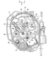
- a seat belt retractor 10 which is a seat belt apparatus according to an embodiment of the invention, includes, as shown in Fig. 1 , a retractor frame 11, and a spindle 12 for winding thereround webbing (not shown) is supported rotatably in the retractor frame 11.
- a retractor spring 13 for biasing the spindle 12 in a seat belt winding direction is attached to the retractor frame 11 by a holder 14 and a cover 15 at one axial end side of the spindle.
- an acceleration sensor 16 which is provided in such a manner as to be tilted about a horizontal axis within the seat belt retractor 10 for detecting a horizontal acceleration of a vehicle
- an inertia element assembly 18 which is disposed within a bearing plate 17 for locking a pull-out operation of a seat belt according to an acceleration detected by the acceleration sensor 16
- an automatic locking retractor (ALR) 19 which is actuated by performing a predetermined webbing pull-out operation for realizing the prevention of rotation of the spindle 12 in a webbing pull-out direction under a normal operation
- a switch mechanism 20 (a so-called reminder switch), which are accommodated a cover 21.
- the automatic locking retractor 19 includes a drive gear 30 to which the rotation of the spindle 12 is transmitted, an ALR lever 31 which is supported in the bearing plate 17 in such a manner as to freely oscillate, an automatic locking retractor assembly 34 including two ALR gears 32, 33 which are supported rotatably on the ALR lever 31 and a pawl 35 which engages with or disengages from a ratchet wheel 18a of the inertia element assembly 18 in response to the oscillation of the ALR lever 31.
- a first ALR projecting portion 30a which is formed into a sector, is provided on a side of the drive gear 30, and a second ALR projecting portion 32a which is brought into abutment with the first ALR projecting portion 30a and a third ALR projecting portion 33a are provided on sides of the ALR gears 32, 33, respectively.
- the ALR lever 31 oscillates by the first ALR projecting portion 30a and the second ALR projecting portion 32a being brought into abutment with each other, and the pawl 35 is brought into engagement with the ratchet wheel 18a, whereby it becomes a locked state.
- the ALR lever 31 oscillates by the first ALR projecting portion 30a and the third ALR projecting portion 33a being brought into abutment with each other, and the pawl 35 is made to disengage from the ratchet wheel 18a, whereby the locking is released.
- the switch mechanism 20 includes the drive gear 30, a switch assembly 41 which outputs an ON/OFF signal according to a belt-worn-state or belt-not-worn state, a switch lever 42 which can oscillate between a first position where the switch is OFF and a second position where the switch is ON in order to shift the switch assembly 41, a first switch gear 43 which meshes with the drive gear 30 and oscillates together with the switch lever 42, a second switch gear 44 which meshes with the first switch gear 43, and a coil spring 45 which is held in the bearing plate 17 and is locked on the switch lever 42 at one end thereof.
- a first switch projecting portion 30b is formed on the side of the drive gear 30 in a different position from the first ALR projecting portion 30a in a circumferential direction.
- a second switch projecting portion 43a and a third switch projecting portion 43b are formed on a side of the first switch gear 43 in different positions in a circumferential direction.
- a fourth switch projecting portion 44a is formed on a side of the second switch gear 44.
- the first switch projecting portion 30b and the second switch projecting portion 43a shift the switch lever 42 from the switch OFF position to the switch ON position by being brought into abutment with each other.
- the third switch projecting portion 43b and the fourth switch projecting portion 44a shift the switch lever 42 from the switch ON position to the switch OFF position by being brought into abutment with each other.
- an abutment position between the first switch projecting portion 30b and the second switch projecting portion 43a and an abutment position between the third switch projecting portion 43b and the fourth switch projecting portion 44a are different from each other in an axial direction of the spindle 12.
- the second switch projecting portion 43a and the third switch projecting portion 43b whi.ch are formed on the first switch gear 43, the second switch projecting 43a is formed lower and closer to the side of the first switch gear 43 than the third switch projecting portion 43b.
- the first switch projecting portion 30b which is brought into abutment with the second switch projecting portion 43a is formed to have substantially the same (or, as in this embodiment, slightly lower than) as the second switch projection 43a (refer to Fig. 2(b) ).
- the fourth switch projecting portion 44a which is brought into abutment with the third switch projecting portion 43b is also formed to have substantially the same (or, as in this embodiment, slightly lower than) as the third switch projecting portion 43b (refer to Fig. 3(b) ).
- the fourth switch projecting portion 44a has an outward recessed portion 44b and is, hence, formed into an L-shaped cross section and prevents the interference of the fourth switch projecting portion 44a with the second switch projecting portion 43a by the second switching projecting portion 43a passing through the interior of the recessed portion 44b when the drive gear completes a predetermined number of times of rotation (in this embodiment, a second rotation from a state in which the seat belt has been pulled out to its full amount) (refer to Fig. 5(b) ).
- the first switch projecting portion is provided in the same position as a tooth of the drive gear 30.
- the second switch projecting portion 43a is provided between adjacent teeth of the first switch gear 43
- the third switch projecting portion 43b is provided in the same position as a tooth of the first switch gear 43.
- the fourth switch projecting portion 44a is provided between adjacent teeth of the second switch gear 44.
- a shifting operation of the switch mechanism 20 will be described.
- the first switch projecting portion 30b and the second switch projecting portion 43a are brought into abutment with each other in a position where the drive gear 30 completes a tenth rotation from a state in which the webbing is pulled out to its full amount.
- the switch lever 42 oscillates around an oscillation center 42a to pass over a shifting point of the coil spring 45, when the switch lever 42 moves to the switch ON position, whereby the switch mechanism 20 is shifted to ON.
- the switch lever 42 oscillates around the oscillation center 42a to pass over the shifting point of the coil spring 45, when the switch lever 42 moves to the switch OFF position, whereby the switch mechanism 20 is shifted to OFF.
- the switch mechanism 20 can be shifted in an ensured fashion within a range from the fully retracted state to the maximum retracting amount (for example, the occupant is a six-year-old child, the seat is slid to a rear position, and the head restraint is lowered to its lowest position).
- the switch mechanism 20 can be shifted in an ensured fashion within a range from the fully retracted state to the maximum retracting amount (for example, the occupant is a six-year-old child, the seat is slid to a rear position, and the head restraint is lowered to its lowest position).
- the webbing is pulled out or retracted, an unintentional interference between the projecting portions is prevented, thereby making it possible to provide a highly reliable seat belt apparatus.
- the shifting of the switch mechanism 20 and the canceling operation of the automatic locking retractor are performed substantially at the same time.
- the automatic locking retractor 19 can be released.
- the invention is not such as to be limited to the embodiment that has been described heretofore but can be modified as required without departing from the spirit and scope of the invention.
- the recessed portion 44b is formed in the fourth switch projecting portion 44a, instead, a recessed portion may be provided in the third switch projecting portion 43b, so as to avoid the interference with the first switch projecting portion 30b.
- the third switch projecting portion 43b is formed to lie closer to the side of the first switch gear 43 than the second switch projecting portion 43a
- one of the first and second switch projecting portions 30b, 43a may be configured to have a recessed portion through which either of the third and fourth switch projecting portions 43b, 44a passes.
- first to fourth switch projecting portions 30b, 43a, 43b, 44a may be formed integrally with the drive gear 30, the first switch gear 43, the second switch gear 44, respectively, or may be mounted thereon as separate members.
Landscapes
- Engineering & Computer Science (AREA)
- Mechanical Engineering (AREA)
- Automation & Control Theory (AREA)
- General Engineering & Computer Science (AREA)
- Automotive Seat Belt Assembly (AREA)
Abstract

Description
- The present invention relates to a seat belt apparatus, and more particularly to a seat belt apparatus which can detect wearing state of a seat belt.
- In a conventional seat belt apparatus, there has been known a construction in which a remainder switch for outputting an ON/OFF signal to an outside for detecting a wearing or non-wearing state of a seat belt is disposed an inside of a seat belt retractor mounted on a vehicle body.
- In the seat belt apparatus, three gears, which are made to link with the rotation of a spindle, are provided, and projecting portions which are formed on sides of the gears are brought into abutment with each other, to thereby drive a switch lever which is adapted to switch on or off the reminder switch.
- Incidentally, in the conventional seat belt apparatus, a projecting portion on the gear disposed at a middle of the three gears is brought into abutment with a projecting portion on one of the remaining gears so as to shift the switch when the belt is pulled out, while the projecting portion is brought into abutment with a projecting portion on the other gear to shift the switch when the belt is retracted. Therefore, a certain extent of deviation in the shifting position of the switch is produced between when the belt is pulled out and when the belt is retracted. Due to this, for example, it is demanded that the reminder switch is shifted properly even in a maximum retracting position resulting when the occupant is restrained.
- On the other hand, it is considered that two projecting portions are provided on the gear disposed at middle in positions where the projecting portions so provided come to be near the projecting portions of the remaining two gears in the shift positions. In this case, however, there has been a possibility that the projecting portions come to interfere with each other unintentionally at a certain number of revolutions.
- The invention has been made with a view to solving the inconveniences described above, and an object thereof is to provide a highly reliable seat belt apparatus which can reduce the extent of deviation in retracting amount of webbing when the switch is shifted or between when the webbing is retracted and when the webbing is pulled out and which can prevent the unintentional interference between the projecting portions when the webbing is operated to be pulled out or retracted.
- The object of the invention will be attained by the following configurations.
- (1) A seat belt apparatus including:
- a rotatable spindle around which a webbing is wound;
- a drive gear to which the rotation of the spindle is transmitted;
- a switch which outputs an ON/OFF signal according to a belt-worn-state or a belt-not-worn-state;
- a switch lever which can oscillate to a first position and a second position in order to shift the switch;
- a first gear which meshes with the drive gear and oscillates together with the switch lever; and
- a second gear which meshes with the first gear;
- the seat belt apparatus being characterized in that;
- a first projecting portion and a second projecting portion are provided on a side of the drive gear and a side of the first gear, respectively, which are capable of being brought into abutment with each other so that the switch lever is shifted from the first position to the second position;
- a third projecting portion and a fourth projecting portion are provided on the side of the first gear and a side of the second gear, respectively, which are capable of being brought into abutment with each other so that the switch lever is shifted from the second position to the first position; and
- an abutment position between the first and second projecting portions and an abutment position between the third and fourth projecting portions differ from each other in an axial direction of the spindle.
- (2) The seat belt apparatus as set forth in Claim 1, characterized in that;
the second projecting portion is formed closer to the side of the first gear than the third projecting portion; and that
one of the third and fourth projecting portions has a recessed portion through which either of the first and second projecting portions passes. - (3) The seat belt apparatus as set forth in Claim 1, characterized in that;
the third projecting portion is formed closer to the side of the first gear than the second projecting portion; and
one of the first and second projecting portions has a recessed portion through which either of the third and fourth projecting portions passes. - (4) The seat belt apparatus as set forth in Claim 1, characterized in that;
the seat belt apparatus further includes an automatic locking retractor adapted to be actuated by performing a predetermined webbing pull-out operation and to realize a prevention of rotation of the spindle in a webbing pull-out direction under a normal operation, and
the prevention of rotation of the spindle in the webbing pull-out direction is cancelled while the switch lever is being shifted from the second position to the first position. Advantage of the Invention - According to the invention, the first projecting portion and the second projecting portion are provided on the side of the drive gear and the side of the first gear, respectively, which are capable of being brought into abutment with each other so that the switch lever is shifted from the first position to the second position, while the third projecting portion and the fourth projecting portion are provided on the side of the first gear and the side of the second gear, respectively, which are capable of being brought into abutment with each other so that the switch lever is shifted from the second position to the first position, and the abutment position between the first and second projecting portions and the abutment position between the third and fourth projecting portions differ from each other in the axial direction of the spindle. By this means, a highly reliable seat belt apparatus can be provided which can reduce the extent of deviation in retracting amount of webbing when the switch is shifted or between when the webbing is retracted and when the webbing is pulled out and which can prevent the unintentional interference between the projecting portions when the webbing is operated to be pulled out or retracted.
-
-
Fig. 1 is an exploded perspective view which illustrates constituent components of a seat belt apparatus which is an embodiment of the invention; -
Fig. 2 (a) is a diagram showing a state in which a first switch projecting portion and a second switch projecting portion are brought into abutment with each other in a position where a drive gear completes a tenth rotation thereof since webbing has been pulled out to its full amount when the webbing is operated to be pulled out; -
Fig. 2 (b) is a sectional view taken along the line II-II inFig. 2(a) ; -
Fig. 3 (a) is a diagram showing a state in which a third switch projecting portion and a fourth switch projecting portion are brought into abutment with each other in a position where the drive gear completes a tenth rotation thereof since webbing has been pulled out to its full amount when the webbing is operated to be retracted, and -
Fig. 3 (b) is a sectional view taken along the line III-III inFig. 3 (a) ; -
Fig. 4 is a diagram showing a state in which a first ALR projecting portion and the second switch projecting portion approach and pass by at a point in time at which the drive gear completes its first rotation since the webbing has been pulled out to its full amount when the webbing is operated to be retracted; -
Fig. 5 (a) is a diagram showing a state in which the second switch projecting portion and the fourth switch projecting portion pass by without interference at a point in time at which the drive gear completes its second rotation since the webbing has been pulled out to its full amount when the webbing is operated to be retracted; -
Fig. 5(b) is a sectional view taken along the line V-V inFig. 5(a) ; and -
Fig. 6 is a diagram showing a state in which the third switch projecting portion and the first ALR projecting portion approach and pass by at a point in time at which the drive gear completes its tenth rotation since the webbing has been pulled out to its full amount when the webbing is operated to be retracted. -
- 10
- seat belt retractor (seat belt apparatus);
- 12
- spindle;
- 20
- switch mechanism (switch);
- 30
- drive gear;
- 30b
- first switch projecting portion (first projecting portion);
- 42
- switch lever;
- 43
- first switch gear (first gear);
- 43a
- second switch projecting portion (second projecting portion);
- 43b
- third switch projecting portion (third projecting portion);
- 44
- second switch gear (second gear);
- 44a
- fourth switch projecting portion (fourth projecting portion)
- Hereinafter, a seat belt apparatus according to an embodiment of the invention will be described in detail by reference to the drawings.
- A
seat belt retractor 10, which is a seat belt apparatus according to an embodiment of the invention, includes, as shown inFig. 1 , aretractor frame 11, and aspindle 12 for winding thereround webbing (not shown) is supported rotatably in theretractor frame 11. - A
retractor spring 13 for biasing thespindle 12 in a seat belt winding direction is attached to theretractor frame 11 by aholder 14 and acover 15 at one axial end side of the spindle. - Provided at the other axial end side of the
spindle 12 are anacceleration sensor 16 which is provided in such a manner as to be tilted about a horizontal axis within theseat belt retractor 10 for detecting a horizontal acceleration of a vehicle, aninertia element assembly 18 which is disposed within a bearingplate 17 for locking a pull-out operation of a seat belt according to an acceleration detected by theacceleration sensor 16, an automatic locking retractor (ALR) 19 which is actuated by performing a predetermined webbing pull-out operation for realizing the prevention of rotation of thespindle 12 in a webbing pull-out direction under a normal operation, and a switch mechanism 20 (a so-called reminder switch), which are accommodated acover 21. - As shown in
Figs. 1 and2 , theautomatic locking retractor 19 includes adrive gear 30 to which the rotation of thespindle 12 is transmitted, anALR lever 31 which is supported in the bearingplate 17 in such a manner as to freely oscillate, an automaticlocking retractor assembly 34 including two ALR gears 32, 33 which are supported rotatably on theALR lever 31 and apawl 35 which engages with or disengages from aratchet wheel 18a of theinertia element assembly 18 in response to the oscillation of theALR lever 31. - A first
ALR projecting portion 30a, which is formed into a sector, is provided on a side of thedrive gear 30, and a secondALR projecting portion 32a which is brought into abutment with the firstALR projecting portion 30a and a thirdALR projecting portion 33a are provided on sides of the ALR gears 32, 33, respectively. In addition, when a predetermined webbing pull-out operation is performed, theALR lever 31 oscillates by the firstALR projecting portion 30a and the secondALR projecting portion 32a being brought into abutment with each other, and thepawl 35 is brought into engagement with theratchet wheel 18a, whereby it becomes a locked state.
On the other hand, when a predetermined webbing retracting operation is performed, theALR lever 31 oscillates by the firstALR projecting portion 30a and the thirdALR projecting portion 33a being brought into abutment with each other, and thepawl 35 is made to disengage from theratchet wheel 18a, whereby the locking is released. - The
switch mechanism 20 includes thedrive gear 30, aswitch assembly 41 which outputs an ON/OFF signal according to a belt-worn-state or belt-not-worn state, aswitch lever 42 which can oscillate between a first position where the switch is OFF and a second position where the switch is ON in order to shift theswitch assembly 41, afirst switch gear 43 which meshes with thedrive gear 30 and oscillates together with theswitch lever 42, asecond switch gear 44 which meshes with thefirst switch gear 43, and acoil spring 45 which is held in the bearingplate 17 and is locked on theswitch lever 42 at one end thereof. - A first
switch projecting portion 30b is formed on the side of thedrive gear 30 in a different position from the firstALR projecting portion 30a in a circumferential direction. A secondswitch projecting portion 43a and a thirdswitch projecting portion 43b are formed on a side of thefirst switch gear 43 in different positions in a circumferential direction. In addition, a fourthswitch projecting portion 44a is formed on a side of thesecond switch gear 44. - The first
switch projecting portion 30b and the secondswitch projecting portion 43a shift theswitch lever 42 from the switch OFF position to the switch ON position by being brought into abutment with each other. In addition, the thirdswitch projecting portion 43b and the fourthswitch projecting portion 44a shift theswitch lever 42 from the switch ON position to the switch OFF position by being brought into abutment with each other. - Here, an abutment position between the first
switch projecting portion 30b and the secondswitch projecting portion 43a and an abutment position between the thirdswitch projecting portion 43b and the fourthswitch projecting portion 44a are different from each other in an axial direction of thespindle 12. Specifically, as shown inFigs. 2 (b) ,3(b) and 5(b), in the secondswitch projecting portion 43a and the thirdswitch projecting portion 43b whi.ch are formed on thefirst switch gear 43, the second switch projecting 43a is formed lower and closer to the side of thefirst switch gear 43 than the thirdswitch projecting portion 43b. - Due to this, the first
switch projecting portion 30b which is brought into abutment with the secondswitch projecting portion 43a is formed to have substantially the same (or, as in this embodiment, slightly lower than) as thesecond switch projection 43a (refer toFig. 2(b) ). In addition, the fourthswitch projecting portion 44a which is brought into abutment with the thirdswitch projecting portion 43b is also formed to have substantially the same (or, as in this embodiment, slightly lower than) as the thirdswitch projecting portion 43b (refer toFig. 3(b) ). - Furthermore, the fourth
switch projecting portion 44a has an outward recessed portion 44b and is, hence, formed into an L-shaped cross section and prevents the interference of the fourthswitch projecting portion 44a with the secondswitch projecting portion 43a by the secondswitching projecting portion 43a passing through the interior of the recessed portion 44b when the drive gear completes a predetermined number of times of rotation (in this embodiment, a second rotation from a state in which the seat belt has been pulled out to its full amount) (refer toFig. 5(b) ). - Note that in this embodiment, the first switch projecting portion is provided in the same position as a tooth of the
drive gear 30. In addition, the secondswitch projecting portion 43a is provided between adjacent teeth of thefirst switch gear 43, and the thirdswitch projecting portion 43b is provided in the same position as a tooth of thefirst switch gear 43. Furthermore, the fourthswitch projecting portion 44a is provided between adjacent teeth of thesecond switch gear 44. - Next, referring to from
Fig.2 to Fig. 5 , a shifting operation of theswitch mechanism 20 will be described. As shown inFig. 2 , when operating the webbing to pull it out, the firstswitch projecting portion 30b and the secondswitch projecting portion 43a are brought into abutment with each other in a position where thedrive gear 30 completes a tenth rotation from a state in which the webbing is pulled out to its full amount. Then, theswitch lever 42 oscillates around anoscillation center 42a to pass over a shifting point of thecoil spring 45, when theswitch lever 42 moves to the switch ON position, whereby theswitch mechanism 20 is shifted to ON. - On the other hand, as shown in
Fig. 3 , when operating the webbing to retract it, the thirdswitch projecting portion 43b and the fourthswitch projecting portion 44a are brought into abutment with each other in a position where thedrive gear 30 completes a tenth rotation from a state in which the webbing is pulled out to its full amount. Then, theswitch lever 42 oscillates around theoscillation center 42a to pass over the shifting point of thecoil spring 45, when theswitch lever 42 moves to the switch OFF position, whereby theswitch mechanism 20 is shifted to OFF. - In addition, as shown in
Fig. 4 , when operating the webbing to retract it, when thedrive gear 30 completes a first rotation (or, depending on a specification, a first rotation and a fifteenth rotation) from a state in which the webbing is pulled out to its full amount, although the firstALR projecting portion 30a and the secondswitch projecting portion 43a approach and pass by, there is no possibility that they are brought into abutment with each other because in the switch ON state, thefirst switch gear 43 lies closer to thesecond switch gear 44 together with theswitch lever 42. - In addition, as shown in
Fig. 5 , when operating the webbing to retract it, when thedrive gear 30 completes a second rotation from a state in which the webbing is pulled out to its full amount, although the secondswitch projecting portion 43a and the fourthswitch projecting portion 44a overlap each other as viewed from the top, as has been described above, because the secondswitch projecting portion 43a passes through the interior of recessed portion 44b of the fourthswitch projecting portion 44a, there is no possibility that theswitch projecting portion 43a and the fourthswitch projecting portion 44a are brought into abutment with each other. - Furthermore, as shown in
Fig. 6 , when operating the webbing to retract it, before the shifting to the switch OFF position occurs inFig. 3 and when thedrive gear 30 completes a tenth rotation from a state in which the webbing is pulled out to its full amount, although the thirdswitch projecting portion 43b and the firstALR projecting portion 30a approach and pass by, in this case, too, because thefirst switch gear 43 lie closer to thesecond switch gear 44, there is no possibility that the thirdswitch projecting portion 43b and the firstALR projecting portion 30a are brought into abutment with each other. - By this means, the extent of deviation in retracting amount of webbing when the
switch mechanism 20 is shifted or between when the webbing is retracted and when the webbing is pulled out can be reduced. In addition, theswitch mechanism 20 can be shifted in an ensured fashion within a range from the fully retracted state to the maximum retracting amount (for example, the occupant is a six-year-old child, the seat is slid to a rear position, and the head restraint is lowered to its lowest position). In addition, when the webbing is pulled out or retracted, an unintentional interference between the projecting portions is prevented, thereby making it possible to provide a highly reliable seat belt apparatus. - In addition, in this embodiment, in the state shown in
Fig. 3 , after the thirdswitch projecting portion 43b and the fourthswitch projecting portion 44a are brought into abutment with each other, while theswitch lever 42 has passed over the shifting point of thecoil spring 45 and is moving to the switch OFF position, the firstALR projecting portion 30a of thedrive gear 30 and the thirdALR projecting portion 33a of theALR gear 33 of theautomatic locking retractor 19 are brought into abutment with each other, whereby the prevention of rotation of thespindle 12 in the webbing pull-out direction is made to be cancelled. - By this means, the shifting of the
switch mechanism 20 and the canceling operation of the automatic locking retractor are performed substantially at the same time. For example, in the event that the webbing is pulled out to its full amount when worn by a six-year-old child so as to actuate theautomatic locking retractor 19 and then the webbing is let retracted to restore the normal wearing state, theautomatic locking retractor 19 can be released. - Note that the invention is not such as to be limited to the embodiment that has been described heretofore but can be modified as required without departing from the spirit and scope of the invention.
While in this embodiment, the recessed portion 44b is formed in the fourthswitch projecting portion 44a, instead, a recessed portion may be provided in the thirdswitch projecting portion 43b, so as to avoid the interference with the firstswitch projecting portion 30b.
In addition, in the event that the thirdswitch projecting portion 43b is formed to lie closer to the side of thefirst switch gear 43 than the secondswitch projecting portion 43a, one of the first and secondswitch projecting portions switch projecting portions - Furthermore, the first to fourth
switch projecting portions drive gear 30, thefirst switch gear 43, thesecond switch gear 44, respectively, or may be mounted thereon as separate members. - The subject patent application is based on the
Japanese Patent Application (No. P.2005-206053) filed on July 14, 2005
Claims (4)
- A seat belt apparatus comprising:a rotatable spindle around which a webbing is wound;a drive gear to which a rotation of the spindle is transmitted;a switch which outputs an ON/OFF signal according to a belt-worn-state or a belt-not-worn-state;a switch lever which is capable of oscillating to a first position and a second position in order to shift the switch;a first gear which meshes with the drive gear and oscillates together with the switch lever; anda second gear which meshes with the first gear;the seat belt apparatus is characterized in that;a first projecting portion and a second projecting portion are provided on a side of the drive gear and a side of the first gear, respectively, which are capable of being brought into abutment with each other so that the switch lever is shifted from the first position to the second position;a third projecting portion and a fourth projecting portion are provided on the side of the first gear and a side of the second gear, respectively, which are capable of being brought into abutment with each other so that the switch lever is shifted from the second position to the first position; andan abutment position between the first and second projecting portions and an abutment position between the third and fourth projecting portions differ from each other in an axial direction of the spindle.
- The seat belt apparatus as set forth in Claim 1,
characterized in that;
the second projecting portion is formed closer to a side of the first gear than the third projecting portion; and
one of the third and fourth projecting portions has a recessed portion through which either of the first and second projecting portions passes. - The seat belt apparatus as set forth in Claim 1,
characterized in that;
the third projecting portion is formed closer to a side of the first gear than the second projecting portion; and
one of the first and second projecting portions has a recessed portion through which either of the third and fourth projecting portions passes. - The seat belt apparatus as set forth in Claim 1,
characterized in that
the seat belt apparatus further comprises an automatic locking retractor adapted to be actuated by performing a predetermined webbing pull-out operation and to realize the prevention of rotation of the spindle in a webbing pull-out direction under a normal operation, and
the prevention of rotation of the spindle in the webbing pull-out direction is cancelled while the switch lever is being shifted from the second position to the first position.
Applications Claiming Priority (2)
| Application Number | Priority Date | Filing Date | Title |
|---|---|---|---|
| JP2005206053 | 2005-07-14 | ||
| PCT/JP2006/311005 WO2007007480A1 (en) | 2005-07-14 | 2006-06-01 | Seatbelt device |
Publications (3)
| Publication Number | Publication Date |
|---|---|
| EP1908651A1 true EP1908651A1 (en) | 2008-04-09 |
| EP1908651A4 EP1908651A4 (en) | 2012-10-31 |
| EP1908651B1 EP1908651B1 (en) | 2013-10-23 |
Family
ID=37636880
Family Applications (1)
| Application Number | Title | Priority Date | Filing Date |
|---|---|---|---|
| EP06756882.4A Active EP1908651B1 (en) | 2005-07-14 | 2006-06-01 | Seatbelt device |
Country Status (6)
| Country | Link |
|---|---|
| US (1) | US7491906B2 (en) |
| EP (1) | EP1908651B1 (en) |
| JP (1) | JP4786655B2 (en) |
| KR (1) | KR100944823B1 (en) |
| CN (1) | CN100595094C (en) |
| WO (1) | WO2007007480A1 (en) |
Families Citing this family (4)
| Publication number | Priority date | Publication date | Assignee | Title |
|---|---|---|---|---|
| JP5848034B2 (en) * | 2011-06-07 | 2016-01-27 | 芦森工業株式会社 | Seat belt retractor |
| WO2013073569A1 (en) * | 2011-11-14 | 2013-05-23 | オートリブ ディベロップメント エービー | Seatbelt device |
| JP6357456B2 (en) * | 2015-10-30 | 2018-07-11 | オートリブ ディベロップメント エービー | Seat belt retractor |
| CN113078015B (en) * | 2021-04-01 | 2022-10-25 | 重庆润泰电气有限公司 | Single 90 degree rotation to position withdrawable safety switch |
Citations (2)
| Publication number | Priority date | Publication date | Assignee | Title |
|---|---|---|---|---|
| US20020189880A1 (en) * | 1999-08-06 | 2002-12-19 | Takata Corporation | Seatbelt retractor |
| US20040188995A1 (en) * | 2001-05-31 | 2004-09-30 | Gunter Clute | Safety belt winder comprising a power limitation system which can be actuated according to the strip of belt pulled out |
Family Cites Families (13)
| Publication number | Priority date | Publication date | Assignee | Title |
|---|---|---|---|---|
| US3767134A (en) * | 1971-06-30 | 1973-10-23 | American Safety Equip | Electrical sensor unit for a safety belt retractor |
| JPS5331168Y2 (en) * | 1973-11-16 | 1978-08-03 | ||
| JPS6040372Y2 (en) * | 1982-06-09 | 1985-12-05 | 株式会社高田工場 | belt winding device |
| JPS61110683A (en) | 1984-11-05 | 1986-05-28 | 三洋電機株式会社 | Luminaire for bicycle |
| US4754105A (en) * | 1987-05-01 | 1988-06-28 | Gateway Industries, Inc. | Seat belt buckle with switch |
| JPH072457B2 (en) * | 1988-07-06 | 1995-01-18 | 日本精工株式会社 | Retractor with webbing winding amount detection mechanism |
| JPH02133960A (en) | 1988-11-15 | 1990-05-23 | Mitsubishi Electric Corp | Writable nonvolatile semiconductor memory device |
| IT1230028B (en) * | 1988-12-16 | 1991-09-24 | Sgs Thomson Microelectronics | MOS SEMICONDUCTIVE DEVICES MANUFACTURING PROCESS WITH A "GETTERING" TREATMENT TO IMPROVE CHARACTERISTICS, AND MOS SEMICONDUCTIVE DEVICES WITH IT OBTAINED |
| JPH02133960U (en) * | 1989-04-14 | 1990-11-07 | ||
| GB2306294B (en) * | 1995-10-23 | 1999-09-15 | Tensator Ltd | Improvements in or relating to a seat belt retractor |
| US5944135A (en) * | 1996-11-14 | 1999-08-31 | Trw Vehicle Safety Systems Inc. | Seat belt buckle with field effect locking indicator and method of use |
| JP2002308046A (en) * | 2001-04-09 | 2002-10-23 | Nsk Autoliv Co Ltd | Seat belt device |
| DE60106916T2 (en) * | 2001-09-27 | 2005-12-08 | Key Safety Systems, Inc., Sterling Heights | Belt retractor with automatic locking mechanism |
-
2006
- 2006-06-01 WO PCT/JP2006/311005 patent/WO2007007480A1/en active Application Filing
- 2006-06-01 CN CN200680025718A patent/CN100595094C/en active Active
- 2006-06-01 JP JP2007524541A patent/JP4786655B2/en active Active
- 2006-06-01 KR KR1020087000987A patent/KR100944823B1/en active IP Right Grant
- 2006-06-01 EP EP06756882.4A patent/EP1908651B1/en active Active
-
2008
- 2008-01-14 US US12/013,794 patent/US7491906B2/en active Active
Patent Citations (2)
| Publication number | Priority date | Publication date | Assignee | Title |
|---|---|---|---|---|
| US20020189880A1 (en) * | 1999-08-06 | 2002-12-19 | Takata Corporation | Seatbelt retractor |
| US20040188995A1 (en) * | 2001-05-31 | 2004-09-30 | Gunter Clute | Safety belt winder comprising a power limitation system which can be actuated according to the strip of belt pulled out |
Non-Patent Citations (1)
| Title |
|---|
| See also references of WO2007007480A1 * |
Also Published As
| Publication number | Publication date |
|---|---|
| WO2007007480A1 (en) | 2007-01-18 |
| KR100944823B1 (en) | 2010-03-03 |
| JP4786655B2 (en) | 2011-10-05 |
| JPWO2007007480A1 (en) | 2009-01-29 |
| EP1908651A4 (en) | 2012-10-31 |
| US7491906B2 (en) | 2009-02-17 |
| US20080116044A1 (en) | 2008-05-22 |
| EP1908651B1 (en) | 2013-10-23 |
| KR20080034125A (en) | 2008-04-18 |
| CN100595094C (en) | 2010-03-24 |
| CN101223062A (en) | 2008-07-16 |
Similar Documents
| Publication | Publication Date | Title |
|---|---|---|
| JP5706757B2 (en) | Seat belt retractor and seat belt device using the same | |
| US6152393A (en) | Webbing winding device | |
| WO2014080702A1 (en) | Seat belt retractor and seat belt device using same | |
| US20090230227A1 (en) | Seat belt retractor and seat belt apparatus employing the same | |
| US20130140869A1 (en) | Seatbelt retractor and seatbelt apparatus having the same | |
| EP1908651A1 (en) | Seatbelt device | |
| JP2005178415A (en) | Webbing winding device | |
| JP3629503B2 (en) | Seat belt retractor with automatic locking mechanism | |
| US20130154337A1 (en) | Seat belt retractor and seat belt apparatus including the same | |
| JP3616811B2 (en) | Seat belt retractor | |
| EP2589516B1 (en) | Seat belt retractor and seat belt apparatus including the same | |
| US4391421A (en) | Retractor for seat belt with an alleviating device | |
| US9150193B2 (en) | Mode detection switch assembly for self-locking dual-mode seat belt retractor | |
| JP5332035B2 (en) | Seat belt retractor | |
| EP0542204B1 (en) | Webbing retractor | |
| US20080079254A1 (en) | Seat belt retractor and seat belt apparatus | |
| JP4624296B2 (en) | Seat belt device | |
| JP3834759B2 (en) | Detent belt winder with retractor switching device | |
| JP6357456B2 (en) | Seat belt retractor | |
| JP4518891B2 (en) | Webbing take-up device | |
| JP4805222B2 (en) | Seat belt device | |
| JP2008265557A (en) | Vehicular seat belt device | |
| JP2008110747A (en) | Seat belt retractor and seat belt apparatus | |
| JP2004090673A (en) | Webbing winder |
Legal Events
| Date | Code | Title | Description |
|---|---|---|---|
| PUAI | Public reference made under article 153(3) epc to a published international application that has entered the european phase |
Free format text: ORIGINAL CODE: 0009012 |
|
| 17P | Request for examination filed |
Effective date: 20080214 |
|
| AK | Designated contracting states |
Kind code of ref document: A1 Designated state(s): AT BE BG CH CY CZ DE DK EE ES FI FR GB GR HU IE IS IT LI LT LU LV MC NL PL PT RO SE SI SK TR |
|
| DAX | Request for extension of the european patent (deleted) | ||
| A4 | Supplementary search report drawn up and despatched |
Effective date: 20121001 |
|
| RIC1 | Information provided on ipc code assigned before grant |
Ipc: B60R 22/34 20060101AFI20120925BHEP Ipc: B60R 22/48 20060101ALI20120925BHEP |
|
| GRAP | Despatch of communication of intention to grant a patent |
Free format text: ORIGINAL CODE: EPIDOSNIGR1 |
|
| INTG | Intention to grant announced |
Effective date: 20130701 |
|
| GRAS | Grant fee paid |
Free format text: ORIGINAL CODE: EPIDOSNIGR3 |
|
| GRAA | (expected) grant |
Free format text: ORIGINAL CODE: 0009210 |
|
| AK | Designated contracting states |
Kind code of ref document: B1 Designated state(s): AT BE BG CH CY CZ DE DK EE ES FI FR GB GR HU IE IS IT LI LT LU LV MC NL PL PT RO SE SI SK TR |
|
| REG | Reference to a national code |
Ref country code: GB Ref legal event code: FG4D |
|
| REG | Reference to a national code |
Ref country code: CH Ref legal event code: EP |
|
| REG | Reference to a national code |
Ref country code: AT Ref legal event code: REF Ref document number: 637390 Country of ref document: AT Kind code of ref document: T Effective date: 20131115 |
|
| REG | Reference to a national code |
Ref country code: IE Ref legal event code: FG4D |
|
| REG | Reference to a national code |
Ref country code: DE Ref legal event code: R096 Ref document number: 602006038955 Country of ref document: DE Effective date: 20131219 |
|
| REG | Reference to a national code |
Ref country code: NL Ref legal event code: VDEP Effective date: 20131023 |
|
| REG | Reference to a national code |
Ref country code: AT Ref legal event code: MK05 Ref document number: 637390 Country of ref document: AT Kind code of ref document: T Effective date: 20131023 |
|
| REG | Reference to a national code |
Ref country code: LT Ref legal event code: MG4D |
|
| PG25 | Lapsed in a contracting state [announced via postgrant information from national office to epo] |
Ref country code: BE Free format text: LAPSE BECAUSE OF FAILURE TO SUBMIT A TRANSLATION OF THE DESCRIPTION OR TO PAY THE FEE WITHIN THE PRESCRIBED TIME-LIMIT Effective date: 20131023 Ref country code: FI Free format text: LAPSE BECAUSE OF FAILURE TO SUBMIT A TRANSLATION OF THE DESCRIPTION OR TO PAY THE FEE WITHIN THE PRESCRIBED TIME-LIMIT Effective date: 20131023 Ref country code: LT Free format text: LAPSE BECAUSE OF FAILURE TO SUBMIT A TRANSLATION OF THE DESCRIPTION OR TO PAY THE FEE WITHIN THE PRESCRIBED TIME-LIMIT Effective date: 20131023 Ref country code: IS Free format text: LAPSE BECAUSE OF FAILURE TO SUBMIT A TRANSLATION OF THE DESCRIPTION OR TO PAY THE FEE WITHIN THE PRESCRIBED TIME-LIMIT Effective date: 20140223 Ref country code: NL Free format text: LAPSE BECAUSE OF FAILURE TO SUBMIT A TRANSLATION OF THE DESCRIPTION OR TO PAY THE FEE WITHIN THE PRESCRIBED TIME-LIMIT Effective date: 20131023 Ref country code: SE Free format text: LAPSE BECAUSE OF FAILURE TO SUBMIT A TRANSLATION OF THE DESCRIPTION OR TO PAY THE FEE WITHIN THE PRESCRIBED TIME-LIMIT Effective date: 20131023 |
|
| PG25 | Lapsed in a contracting state [announced via postgrant information from national office to epo] |
Ref country code: LV Free format text: LAPSE BECAUSE OF FAILURE TO SUBMIT A TRANSLATION OF THE DESCRIPTION OR TO PAY THE FEE WITHIN THE PRESCRIBED TIME-LIMIT Effective date: 20131023 Ref country code: ES Free format text: LAPSE BECAUSE OF FAILURE TO SUBMIT A TRANSLATION OF THE DESCRIPTION OR TO PAY THE FEE WITHIN THE PRESCRIBED TIME-LIMIT Effective date: 20131023 Ref country code: AT Free format text: LAPSE BECAUSE OF FAILURE TO SUBMIT A TRANSLATION OF THE DESCRIPTION OR TO PAY THE FEE WITHIN THE PRESCRIBED TIME-LIMIT Effective date: 20131023 Ref country code: CY Free format text: LAPSE BECAUSE OF FAILURE TO SUBMIT A TRANSLATION OF THE DESCRIPTION OR TO PAY THE FEE WITHIN THE PRESCRIBED TIME-LIMIT Effective date: 20131023 |
|
| PG25 | Lapsed in a contracting state [announced via postgrant information from national office to epo] |
Ref country code: PT Free format text: LAPSE BECAUSE OF FAILURE TO SUBMIT A TRANSLATION OF THE DESCRIPTION OR TO PAY THE FEE WITHIN THE PRESCRIBED TIME-LIMIT Effective date: 20140224 |
|
| REG | Reference to a national code |
Ref country code: DE Ref legal event code: R097 Ref document number: 602006038955 Country of ref document: DE |
|
| PG25 | Lapsed in a contracting state [announced via postgrant information from national office to epo] |
Ref country code: EE Free format text: LAPSE BECAUSE OF FAILURE TO SUBMIT A TRANSLATION OF THE DESCRIPTION OR TO PAY THE FEE WITHIN THE PRESCRIBED TIME-LIMIT Effective date: 20131023 |
|
| PG25 | Lapsed in a contracting state [announced via postgrant information from national office to epo] |
Ref country code: SK Free format text: LAPSE BECAUSE OF FAILURE TO SUBMIT A TRANSLATION OF THE DESCRIPTION OR TO PAY THE FEE WITHIN THE PRESCRIBED TIME-LIMIT Effective date: 20131023 Ref country code: CZ Free format text: LAPSE BECAUSE OF FAILURE TO SUBMIT A TRANSLATION OF THE DESCRIPTION OR TO PAY THE FEE WITHIN THE PRESCRIBED TIME-LIMIT Effective date: 20131023 Ref country code: PL Free format text: LAPSE BECAUSE OF FAILURE TO SUBMIT A TRANSLATION OF THE DESCRIPTION OR TO PAY THE FEE WITHIN THE PRESCRIBED TIME-LIMIT Effective date: 20131023 Ref country code: RO Free format text: LAPSE BECAUSE OF FAILURE TO SUBMIT A TRANSLATION OF THE DESCRIPTION OR TO PAY THE FEE WITHIN THE PRESCRIBED TIME-LIMIT Effective date: 20131023 Ref country code: IT Free format text: LAPSE BECAUSE OF FAILURE TO SUBMIT A TRANSLATION OF THE DESCRIPTION OR TO PAY THE FEE WITHIN THE PRESCRIBED TIME-LIMIT Effective date: 20131023 |
|
| PLBE | No opposition filed within time limit |
Free format text: ORIGINAL CODE: 0009261 |
|
| STAA | Information on the status of an ep patent application or granted ep patent |
Free format text: STATUS: NO OPPOSITION FILED WITHIN TIME LIMIT |
|
| PG25 | Lapsed in a contracting state [announced via postgrant information from national office to epo] |
Ref country code: DK Free format text: LAPSE BECAUSE OF FAILURE TO SUBMIT A TRANSLATION OF THE DESCRIPTION OR TO PAY THE FEE WITHIN THE PRESCRIBED TIME-LIMIT Effective date: 20131023 |
|
| 26N | No opposition filed |
Effective date: 20140724 |
|
| REG | Reference to a national code |
Ref country code: DE Ref legal event code: R097 Ref document number: 602006038955 Country of ref document: DE Effective date: 20140724 |
|
| PG25 | Lapsed in a contracting state [announced via postgrant information from national office to epo] |
Ref country code: LU Free format text: LAPSE BECAUSE OF FAILURE TO SUBMIT A TRANSLATION OF THE DESCRIPTION OR TO PAY THE FEE WITHIN THE PRESCRIBED TIME-LIMIT Effective date: 20140601 Ref country code: MC Free format text: LAPSE BECAUSE OF FAILURE TO SUBMIT A TRANSLATION OF THE DESCRIPTION OR TO PAY THE FEE WITHIN THE PRESCRIBED TIME-LIMIT Effective date: 20131023 |
|
| REG | Reference to a national code |
Ref country code: CH Ref legal event code: PL |
|
| PG25 | Lapsed in a contracting state [announced via postgrant information from national office to epo] |
Ref country code: SI Free format text: LAPSE BECAUSE OF FAILURE TO SUBMIT A TRANSLATION OF THE DESCRIPTION OR TO PAY THE FEE WITHIN THE PRESCRIBED TIME-LIMIT Effective date: 20131023 |
|
| REG | Reference to a national code |
Ref country code: IE Ref legal event code: MM4A |
|
| PG25 | Lapsed in a contracting state [announced via postgrant information from national office to epo] |
Ref country code: LI Free format text: LAPSE BECAUSE OF NON-PAYMENT OF DUE FEES Effective date: 20140630 Ref country code: IE Free format text: LAPSE BECAUSE OF NON-PAYMENT OF DUE FEES Effective date: 20140601 Ref country code: CH Free format text: LAPSE BECAUSE OF NON-PAYMENT OF DUE FEES Effective date: 20140630 |
|
| PG25 | Lapsed in a contracting state [announced via postgrant information from national office to epo] |
Ref country code: BG Free format text: LAPSE BECAUSE OF FAILURE TO SUBMIT A TRANSLATION OF THE DESCRIPTION OR TO PAY THE FEE WITHIN THE PRESCRIBED TIME-LIMIT Effective date: 20131023 |
|
| REG | Reference to a national code |
Ref country code: FR Ref legal event code: PLFP Year of fee payment: 11 |
|
| PG25 | Lapsed in a contracting state [announced via postgrant information from national office to epo] |
Ref country code: GR Free format text: LAPSE BECAUSE OF FAILURE TO SUBMIT A TRANSLATION OF THE DESCRIPTION OR TO PAY THE FEE WITHIN THE PRESCRIBED TIME-LIMIT Effective date: 20140124 |
|
| PG25 | Lapsed in a contracting state [announced via postgrant information from national office to epo] |
Ref country code: TR Free format text: LAPSE BECAUSE OF FAILURE TO SUBMIT A TRANSLATION OF THE DESCRIPTION OR TO PAY THE FEE WITHIN THE PRESCRIBED TIME-LIMIT Effective date: 20131023 Ref country code: HU Free format text: LAPSE BECAUSE OF FAILURE TO SUBMIT A TRANSLATION OF THE DESCRIPTION OR TO PAY THE FEE WITHIN THE PRESCRIBED TIME-LIMIT; INVALID AB INITIO Effective date: 20060601 |
|
| REG | Reference to a national code |
Ref country code: FR Ref legal event code: PLFP Year of fee payment: 12 |
|
| REG | Reference to a national code |
Ref country code: FR Ref legal event code: PLFP Year of fee payment: 13 |
|
| PGFP | Annual fee paid to national office [announced via postgrant information from national office to epo] |
Ref country code: FR Payment date: 20230623 Year of fee payment: 18 Ref country code: DE Payment date: 20230620 Year of fee payment: 18 |
|
| PGFP | Annual fee paid to national office [announced via postgrant information from national office to epo] |
Ref country code: GB Payment date: 20230622 Year of fee payment: 18 |