EP1908650B1 - Deformable part for the front part of a vehicle - Google Patents
Deformable part for the front part of a vehicle Download PDFInfo
- Publication number
- EP1908650B1 EP1908650B1 EP07380098A EP07380098A EP1908650B1 EP 1908650 B1 EP1908650 B1 EP 1908650B1 EP 07380098 A EP07380098 A EP 07380098A EP 07380098 A EP07380098 A EP 07380098A EP 1908650 B1 EP1908650 B1 EP 1908650B1
- Authority
- EP
- European Patent Office
- Prior art keywords
- straight sections
- central section
- vehicle
- symmetric
- openings
- Prior art date
- Legal status (The legal status is an assumption and is not a legal conclusion. Google has not performed a legal analysis and makes no representation as to the accuracy of the status listed.)
- Not-in-force
Links
Images


Classifications
-
- B—PERFORMING OPERATIONS; TRANSPORTING
- B60—VEHICLES IN GENERAL
- B60R—VEHICLES, VEHICLE FITTINGS, OR VEHICLE PARTS, NOT OTHERWISE PROVIDED FOR
- B60R19/00—Wheel guards; Radiator guards, e.g. grilles; Obstruction removers; Fittings damping bouncing force in collisions
- B60R19/02—Bumpers, i.e. impact receiving or absorbing members for protecting vehicles or fending off blows from other vehicles or objects
- B60R19/18—Bumpers, i.e. impact receiving or absorbing members for protecting vehicles or fending off blows from other vehicles or objects characterised by the cross-section; Means within the bumper to absorb impact
-
- B—PERFORMING OPERATIONS; TRANSPORTING
- B60—VEHICLES IN GENERAL
- B60R—VEHICLES, VEHICLE FITTINGS, OR VEHICLE PARTS, NOT OTHERWISE PROVIDED FOR
- B60R21/00—Arrangements or fittings on vehicles for protecting or preventing injuries to occupants or pedestrians in case of accidents or other traffic risks
- B60R21/34—Protecting non-occupants of a vehicle, e.g. pedestrians
-
- B—PERFORMING OPERATIONS; TRANSPORTING
- B60—VEHICLES IN GENERAL
- B60R—VEHICLES, VEHICLE FITTINGS, OR VEHICLE PARTS, NOT OTHERWISE PROVIDED FOR
- B60R19/00—Wheel guards; Radiator guards, e.g. grilles; Obstruction removers; Fittings damping bouncing force in collisions
- B60R19/02—Bumpers, i.e. impact receiving or absorbing members for protecting vehicles or fending off blows from other vehicles or objects
- B60R19/18—Bumpers, i.e. impact receiving or absorbing members for protecting vehicles or fending off blows from other vehicles or objects characterised by the cross-section; Means within the bumper to absorb impact
- B60R2019/1806—Structural beams therefor, e.g. shock-absorbing
- B60R2019/1813—Structural beams therefor, e.g. shock-absorbing made of metal
-
- B—PERFORMING OPERATIONS; TRANSPORTING
- B60—VEHICLES IN GENERAL
- B60R—VEHICLES, VEHICLE FITTINGS, OR VEHICLE PARTS, NOT OTHERWISE PROVIDED FOR
- B60R21/00—Arrangements or fittings on vehicles for protecting or preventing injuries to occupants or pedestrians in case of accidents or other traffic risks
- B60R21/34—Protecting non-occupants of a vehicle, e.g. pedestrians
- B60R2021/343—Protecting non-occupants of a vehicle, e.g. pedestrians using deformable body panel, bodywork or components
Definitions
- the present invention relates to a deformable part for reducing the effect of frontal impacts in vehicles, and more specifically for being used as a means of protecting pedestrians in the event of being hit.
- the part of the invention is designed as a means which allows absorbing part of the energy released due to the effect of the frontal impact of a vehicle against a pedestrian, for which purpose said part deforms upon receiving the impact caused by hitting the pedestrian.
- the foams used as an alternative solution have limitations relating to compressibility, which is about 80%, and in relation to the gradual hardening in the compression process. This means that not all the available space is used because on one hand 20% of the distance is unused due to the incompressibility of the foam, and on the other hand energy absorption capacity is lost.
- EP 1 199 224 which corresponds to the preamble of claim 1, discloses a bumper assembly having a hook angled towards end of door column and provided to engage an opening in an inner shell metal of a vehicle door.
- the bumper assembly has hat-shaped cross-section.
- the hook is arranged at the end face of end sections of hat-shaped profiled section. The end sections are tapered towards the hook.
- the object of the present invention is to eliminate the drawbacks described above, allowing to reduce the size of the space reserved for the deformation area in the event that its dimensions represent a problem for the design of the automobile.
- a deformable metal part having the features claim 1, is provided configured so that it absorbs most of the initial energy, saving space in the deformation area.
- the deformable metal part discussed obtains absorbing a larger amount of initial energy, therefore the deceleration of the impact increases sooner. Displacement is thus decreased, allowing reserving a smaller space.
- the part of the invention can be placed in the upper, middle or lower part of the frontal area, or in all of them, in order to obtain a greater protective effect.
- the deformable part object of the present invention is formed by a sheet metal profile which can be obtained from sheet metal having a rectangular contour and in which a profile is obtained by means of longitudinal shapings having in a sectional view a curved central section, which is limited between first converging straight sections that are identical and symmetric to one another, followed by second diverging straight sections, also identical and symmetric to one another.
- a sheet metal profile which can be obtained from sheet metal having a rectangular contour and in which a profile is obtained by means of longitudinal shapings having in a sectional view a curved central section, which is limited between first converging straight sections that are identical and symmetric to one another, followed by second diverging straight sections, also identical and symmetric to one another.
- the edges separating the curved central area of the areas corresponding to the first straight sections are crossed by openings partially extending on both areas in the transverse direction.
- the deformable part of the invention is thus configured by a grooved profile, the longitudinal opening of which partially narrows and ends in the diverging end sections.
- the openings crossing the edges separating the curved central sections of the straight adjacent sections weaken the corresponding areas acting by way of hinges for facilitating the deformation of the curved central area in the event of impact in order to obtain the aforementioned energy absorption.
- the length of the curved section is equal to the sum of the length of the first straight sections plus the distance separating the angles or bends formed between the first and second straight sections.
- the dimensions of the metal part are thus determined so as to prevent greater displacement in the deformation process.
- the part deforms, being compressed over 95% in the event of impact.
- the deformable part of the invention allows making better use of the space reserved for the deformation of the metal part. This is due to the fact that said part has greater compressibility than foam and absorbs a greater amount of energy, especially at the beginning of the impact, which involves using a smaller deformation space. Controlling the deceleration of impacts is especially advantageous because it obtains greater control over the force/deformation curve.
- the portions of the profile corresponding to the second straight sections will be those portions intended to be fixed to the stiff element of the structure of the vehicle, for which purpose they can be provided with holes and/or notches formed from their free longitudinal edge.
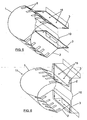
- the deformable part of the invention shown in Figure 1 consists of a metal profile, which can be obtained from sheet metal having a rectangular contour in which a series of shapings are made which allow obtaining a profile, the section of which includes a curved central section, having reference number 1, which is limited along its longitudinal edges by first identical and symmetric converging straight sections 2, followed by second identical and diverging also straight sections 3.
- Edges 4 are determined along the profile between the central section 1 and the first straight sections 2.
- a second edge or angle having reference number 5 is likewise determined along the profile between the first straight sections 2 and the second straight sections 3.
- the edges 4 are crossed by openings 6 partially extending over the curved area, corresponding to section 1, and over the planar areas corresponding to the first straight sections 2. These openings 6 define a reduction of strength and define intermediate bridges 7 acting by way of a hinge for facilitating the deformation of the central section 1.
- the end straight sections 3 can have holes or notches 8 for their assembly in the vehicle, as will be explained below.
- the length of the curved section 1 is equal to the sum of the straight sections 2 plus the distance D separating the edges 5.
- the described part is intended, as shown in Figure 2 , for being assembled between the body or component forming the outer surface 8 of the front of the vehicle and stiff inner parts thereof which can be located in it upper part and have reference number 9, or which can consist of the cross member 10 of the bumper.
- the part of the invention has reference number 11 and it can be seen how it is arranged between the discussed elements, a small separation being necessary between the outer surface 8 of the vehicle and the stiff elements 9 or 10.
Landscapes
- Engineering & Computer Science (AREA)
- Mechanical Engineering (AREA)
- Vibration Dampers (AREA)
- Body Structure For Vehicles (AREA)
- Window Of Vehicle (AREA)
- Vehicle Interior And Exterior Ornaments, Soundproofing, And Insulation (AREA)
Abstract
Description
- The present invention relates to a deformable part for reducing the effect of frontal impacts in vehicles, and more specifically for being used as a means of protecting pedestrians in the event of being hit.
- The part of the invention is designed as a means which allows absorbing part of the energy released due to the effect of the frontal impact of a vehicle against a pedestrian, for which purpose said part deforms upon receiving the impact caused by hitting the pedestrian.
- Due to the requirements for protecting pedestrians, it is necessary to provide vehicles with a frontal non-aggressive deformation area between the outer elements of the vehicle and the stiff inner parts.
- An empty space is currently left between the outer elements of the vehicle and the stiff inner parts for deformation, or, in the event of there being insufficient space, foam is added between the stiff inner areas of the vehicle and the outer elements.
- Current design trends of vehicle exteriors are limited due to the need to reserve a certain sized space for the deformation of the sheet in the event of impact. This involves a more complex problem and increases the cost of placing the mechanical and electric elements in the frontal area of the vehicle.
- The foams used as an alternative solution have limitations relating to compressibility, which is about 80%, and in relation to the gradual hardening in the compression process. This means that not all the available space is used because on one hand 20% of the distance is unused due to the incompressibility of the foam, and on the other hand energy absorption capacity is lost.
-
EP 1 199 224claim 1, discloses a bumper assembly having a hook angled towards end of door column and provided to engage an opening in an inner shell metal of a vehicle door. The bumper assembly has hat-shaped cross-section. The hook is arranged at the end face of end sections of hat-shaped profiled section. The end sections are tapered towards the hook. - The object of the present invention is to eliminate the drawbacks described above, allowing to reduce the size of the space reserved for the deformation area in the event that its dimensions represent a problem for the design of the automobile.
- To that end, according to the invention a deformable metal part, having the
features claim 1, is provided configured so that it absorbs most of the initial energy, saving space in the deformation area. - The deformable metal part discussed obtains absorbing a larger amount of initial energy, therefore the deceleration of the impact increases sooner. Displacement is thus decreased, allowing reserving a smaller space.
- The part of the invention can be placed in the upper, middle or lower part of the frontal area, or in all of them, in order to obtain a greater protective effect.
- The deformable part object of the present invention is formed by a sheet metal profile which can be obtained from sheet metal having a rectangular contour and in which a profile is obtained by means of longitudinal shapings having in a sectional view a curved central section, which is limited between first converging straight sections that are identical and symmetric to one another, followed by second diverging straight sections, also identical and symmetric to one another. In this profile, the edges separating the curved central area of the areas corresponding to the first straight sections are crossed by openings partially extending on both areas in the transverse direction.
- The deformable part of the invention is thus configured by a grooved profile, the longitudinal opening of which partially narrows and ends in the diverging end sections. The openings crossing the edges separating the curved central sections of the straight adjacent sections weaken the corresponding areas acting by way of hinges for facilitating the deformation of the curved central area in the event of impact in order to obtain the aforementioned energy absorption.
- According to another feature of the invention, in relation to the section of the profile, the length of the curved section is equal to the sum of the length of the first straight sections plus the distance separating the angles or bends formed between the first and second straight sections. The dimensions of the metal part are thus determined so as to prevent greater displacement in the deformation process.
- With the described configuration, the part deforms, being compressed over 95% in the event of impact.
- The deformable part of the invention allows making better use of the space reserved for the deformation of the metal part. This is due to the fact that said part has greater compressibility than foam and absorbs a greater amount of energy, especially at the beginning of the impact, which involves using a smaller deformation space. Controlling the deceleration of impacts is especially advantageous because it obtains greater control over the force/deformation curve.
- The portions of the profile corresponding to the second straight sections will be those portions intended to be fixed to the stiff element of the structure of the vehicle, for which purpose they can be provided with holes and/or notches formed from their free longitudinal edge.
- The features and advantages of the part of the invention will be better understood with the following description made in reference to the attached drawings in which a non-limiting embodiment has been shown.
- In the drawings:
-
Figure 1 is a perspective view of a deformable part formed according to the invention. -
Figure 2 shows a longitudinal vertical section view of the front of a vehicle, showing the possible location of the part ofFigure 1 . -
Figure 3 shows a schematic section view of an example of deformation due to a frontal impact of the vehicle due, for example, to hitting a pedestrian. -
Figure 4 is a force/displacement graph comparing deformation of the foam with the deformation of the part of the invention. -
Figure 5 shows a perspective view of an example of the connection of the part of the invention to the cross member of the bumper of a vehicle. -
Figure 6 is a view similar to that ofFigure 5 , showing a possible variation of the connection of the deformable part to the cross member of the vehicle. - The deformable part of the invention, shown in
Figure 1 consists of a metal profile, which can be obtained from sheet metal having a rectangular contour in which a series of shapings are made which allow obtaining a profile, the section of which includes a curved central section, havingreference number 1, which is limited along its longitudinal edges by first identical and symmetric convergingstraight sections 2, followed by second identical and diverging alsostraight sections 3. -
Edges 4 are determined along the profile between thecentral section 1 and the firststraight sections 2. A second edge or angle havingreference number 5 is likewise determined along the profile between the firststraight sections 2 and the secondstraight sections 3. - According to another feature of the invention, the
edges 4 are crossed byopenings 6 partially extending over the curved area, corresponding tosection 1, and over the planar areas corresponding to the firststraight sections 2. Theseopenings 6 define a reduction of strength and define intermediate bridges 7 acting by way of a hinge for facilitating the deformation of thecentral section 1. - The end
straight sections 3 can have holes ornotches 8 for their assembly in the vehicle, as will be explained below. - In
part 1, the length of thecurved section 1 is equal to the sum of thestraight sections 2 plus the distance D separating theedges 5. - The described part is intended, as shown in
Figure 2 , for being assembled between the body or component forming theouter surface 8 of the front of the vehicle and stiff inner parts thereof which can be located in it upper part and havereference number 9, or which can consist of thecross member 10 of the bumper. InFigure 2 the part of the invention hasreference number 11 and it can be seen how it is arranged between the discussed elements, a small separation being necessary between theouter surface 8 of the vehicle and thestiff elements -
Figure 3 schematically shows an example of deformation of thepart 11 connected to the upperstiff part 9 of the vehicle as a result of the impact caused against a body orpedestrian 12. -
Figure 4 shows a force/displacement graph comparing the deformation of the foam with the deformation of the metal part of the invention. The dotted curve, havingreference number 13, shows the performance of the foam system, whereas the continuous line, havingreference number 14, shows the performance of the metal part of the invention. The y-axis indicates the level of force applied and the x-axis indicates the displacement of the part in the deformation area. It can be seen in this graph how at the beginning of the impact the metal part absorbs a larger amount of energy and has less displacement than the foam. -
Figure 5 shows an example of the connection of thepart 11 to thecross member 10 of the bumper. It can be seen how the endstraight sections 3 of the part are in a position considerably parallel and haveholes 15 for their fixing to thecross member 10 of the bumper, for example by means of screws. - In the case of
Figure 6 , the endstraight sections 3 are bent outwardly and are located in a considerably coplanar position, also havingholes 15 for their fixing to thecross member 10.
Claims (3)
- A deformable part (11) for reducing the effect of frontal impacts in vehicles, that is formed by a sheet metal profile which, in a sectional view, has a central section (1) limited between first identical and symmetric straight sections (2), followed by second also respectively identical and symmetric straight sections (3), the first straight sections (2) being crossed by openings (6) extending in a transverse direction,
characterized in that:1a) the central section (1) is curved;1b) the first identical and symmetric straight sections (2) are converging;1c) the second identical and symmetric straight sections (3) are diverging;1d) edges (4) formed between the curved central section (1) and the first straight sections (2) are crossed by the openings (6) extending in the transverse direction;1e) the openings (6) partially extend over both, the curved central section (1) and the first straight sections (2) in the transverse direction. - A deformable part (11) according to claim 1, characterized in that in a sectional view, the length of the curred central section (1) is equal to the sum of the length of the first straight sections (2) plus a distance (D) separating intersection points (5) formed between the first straight sections (2) and the second straight sections (3).
- A deformable part (11) according to claim 1, characterized in that the portions of the profile corresponding to the second straight sections (3) have holes and/or notches (8) for their coupling and fixing to a stiff element of the structure of the vehicle.
Applications Claiming Priority (1)
| Application Number | Priority Date | Filing Date | Title |
|---|---|---|---|
| ES200602159U ES1063711Y (en) | 2006-10-03 | 2006-10-03 | DEFORMABLE PIECE TO REDUCE THE EFFECT OF FRONT IMPACTS OF VEHICLES. |
Publications (2)
| Publication Number | Publication Date |
|---|---|
| EP1908650A1 EP1908650A1 (en) | 2008-04-09 |
| EP1908650B1 true EP1908650B1 (en) | 2010-11-24 |
Family
ID=37565263
Family Applications (1)
| Application Number | Title | Priority Date | Filing Date |
|---|---|---|---|
| EP07380098A Not-in-force EP1908650B1 (en) | 2006-10-03 | 2007-04-11 | Deformable part for the front part of a vehicle |
Country Status (4)
| Country | Link |
|---|---|
| EP (1) | EP1908650B1 (en) |
| AT (1) | ATE489267T1 (en) |
| DE (1) | DE602007010709D1 (en) |
| ES (2) | ES1063711Y (en) |
Cited By (2)
| Publication number | Priority date | Publication date | Assignee | Title |
|---|---|---|---|---|
| DE102011121397A1 (en) * | 2011-12-17 | 2013-07-04 | Gm Global Technology Operations, Llc | Bumper for motor vehicle e.g. passenger car, has deformable barrier element having wall portions with outside edges that are vertically movable during transition from non-deformed state to deformed state |
| DE102004024468B4 (en) * | 2004-05-14 | 2017-08-03 | Volkswagen Ag | Impact-damping component arrangement for a vehicle, in particular bumper arrangement for a motor vehicle |
Families Citing this family (7)
| Publication number | Priority date | Publication date | Assignee | Title |
|---|---|---|---|---|
| FR2923782B1 (en) * | 2007-11-19 | 2010-01-08 | Peugeot Citroen Automobiles Sa | FRONT BLOCK STRUCTURE OF A MOTOR VEHICLE AND A MOTOR VEHICLE COMPRISING SUCH A STRUCTURE |
| DE102008019510A1 (en) * | 2008-04-18 | 2009-10-22 | Volkswagen Ag | Bumper arrangement for vehicle i.e. motor vehicle, has bumper cross beam comprising energy-absorbing deformation element which covers front-sided partial area of bumper cross beam in vehicle height direction |
| DE102009012941A1 (en) * | 2009-03-12 | 2010-09-16 | Volkswagen Ag | Safety device for use in nose of body of passenger car for protecting pedestrian, during collision or off-set crash in low speed range, has additional deformation element provided between fairing unit and mounting carrier |
| DE102009025209A1 (en) * | 2009-06-17 | 2010-12-30 | Audi Ag | Method for installing a deformation element, as well as deformation element |
| JP2017217991A (en) * | 2016-06-07 | 2017-12-14 | マツダ株式会社 | Vehicle front structure |
| JP6319365B2 (en) * | 2016-06-07 | 2018-05-09 | マツダ株式会社 | Front body structure |
| US9855914B1 (en) * | 2016-07-08 | 2018-01-02 | Toyota Motor Engineering & Manufacturing North America, Inc. | Deformable energy absorber structures for front hood assemblies of vehicles |
Family Cites Families (2)
| Publication number | Priority date | Publication date | Assignee | Title |
|---|---|---|---|---|
| ATE238180T1 (en) | 2000-10-19 | 2003-05-15 | Benteler Automobiltechnik Gmbh | BUMPER ARRANGEMENT |
| DE102005020730A1 (en) * | 2005-05-04 | 2006-10-05 | Audi Ag | Bumper system for motor vehicle, has hollow profile sections that are arranged one behind the other, such that pedestrian legs comes in contact only with individual sections, during collision of pedestrian with vehicle |
-
2006
- 2006-10-03 ES ES200602159U patent/ES1063711Y/en not_active Expired - Fee Related
-
2007
- 2007-04-11 DE DE602007010709T patent/DE602007010709D1/en active Active
- 2007-04-11 AT AT07380098T patent/ATE489267T1/en not_active IP Right Cessation
- 2007-04-11 EP EP07380098A patent/EP1908650B1/en not_active Not-in-force
- 2007-04-11 ES ES07380098T patent/ES2357147T3/en active Active
Cited By (2)
| Publication number | Priority date | Publication date | Assignee | Title |
|---|---|---|---|---|
| DE102004024468B4 (en) * | 2004-05-14 | 2017-08-03 | Volkswagen Ag | Impact-damping component arrangement for a vehicle, in particular bumper arrangement for a motor vehicle |
| DE102011121397A1 (en) * | 2011-12-17 | 2013-07-04 | Gm Global Technology Operations, Llc | Bumper for motor vehicle e.g. passenger car, has deformable barrier element having wall portions with outside edges that are vertically movable during transition from non-deformed state to deformed state |
Also Published As
| Publication number | Publication date |
|---|---|
| ES1063711U (en) | 2006-11-16 |
| ES2357147T3 (en) | 2011-04-19 |
| EP1908650A1 (en) | 2008-04-09 |
| DE602007010709D1 (en) | 2011-01-05 |
| ES1063711Y (en) | 2007-02-16 |
| ATE489267T1 (en) | 2010-12-15 |
Similar Documents
| Publication | Publication Date | Title |
|---|---|---|
| EP1908650B1 (en) | Deformable part for the front part of a vehicle | |
| US6793246B2 (en) | Knee support for occupants | |
| JP2607897Y2 (en) | Safety beam | |
| CN100522719C (en) | Locking device having an actuating lever for an adjustable steering column | |
| CN109963751B (en) | Bumper beam with ribs on several walls of the beam | |
| KR20140067958A (en) | Unitary energy absorbing assembly and method of making the same | |
| CN110588556A (en) | Bumper system | |
| RU116827U1 (en) | VEHICLE STAND WITH HOLE HAVING AN EXTENDED CORNER EDGE (OPTIONS) | |
| US5711562A (en) | Bumper assembly for vehicles | |
| CN110316122A (en) | The front body structure of vehicle | |
| EP1726490B1 (en) | Vehicle body front part structure of automobile | |
| JP2004532770A (en) | Automobile body with flexible mounted hood | |
| EP1262374B1 (en) | Crash energy absorbing element | |
| US9598110B2 (en) | Vehicle storage compartment assembly | |
| US7243981B2 (en) | Vehicle body deformation control assembly | |
| KR100916148B1 (en) | Car Crash Box | |
| US11623692B2 (en) | Deformable rear crossmembers with special extrusion section design for bending down in crash loadcases | |
| CN114096440B (en) | Front underrun protection device for heavy vehicles | |
| DE102006015403B4 (en) | Front hood for a passenger car | |
| RU2587747C1 (en) | Damping element for vehicle door panel assembly with said damper and vehicle with said door panel assembly | |
| KR20110051694A (en) | Front seat cross member reinforcement structure | |
| JPH0820297A (en) | Bumper reinforcement | |
| US6957844B2 (en) | Mounting plate for vehicle door reinforcement members | |
| DE10137911A1 (en) | Bumper support for improved pedestrian protection in motor vehicles | |
| KR102592572B1 (en) | Guard rail |
Legal Events
| Date | Code | Title | Description |
|---|---|---|---|
| PUAI | Public reference made under article 153(3) epc to a published international application that has entered the european phase |
Free format text: ORIGINAL CODE: 0009012 |
|
| AK | Designated contracting states |
Kind code of ref document: A1 Designated state(s): AT BE BG CH CY CZ DE DK EE ES FI FR GB GR HU IE IS IT LI LT LU LV MC MT NL PL PT RO SE SI SK TR |
|
| AX | Request for extension of the european patent |
Extension state: AL BA HR MK RS |
|
| 17P | Request for examination filed |
Effective date: 20070412 |
|
| AKX | Designation fees paid |
Designated state(s): AT BE BG CH CY CZ DE DK EE ES FI FR GB GR HU IE IS IT LI LT LU LV MC MT NL PL PT RO SE SI SK TR |
|
| 17Q | First examination report despatched |
Effective date: 20090123 |
|
| R17C | First examination report despatched (corrected) |
Effective date: 20090803 |
|
| R17C | First examination report despatched (corrected) |
Effective date: 20090528 |
|
| GRAP | Despatch of communication of intention to grant a patent |
Free format text: ORIGINAL CODE: EPIDOSNIGR1 |
|
| GRAS | Grant fee paid |
Free format text: ORIGINAL CODE: EPIDOSNIGR3 |
|
| GRAA | (expected) grant |
Free format text: ORIGINAL CODE: 0009210 |
|
| AK | Designated contracting states |
Kind code of ref document: B1 Designated state(s): AT BE BG CH CY CZ DE DK EE ES FI FR GB GR HU IE IS IT LI LT LU LV MC MT NL PL PT RO SE SI SK TR |
|
| REG | Reference to a national code |
Ref country code: GB Ref legal event code: FG4D |
|
| REG | Reference to a national code |
Ref country code: CH Ref legal event code: EP |
|
| REG | Reference to a national code |
Ref country code: IE Ref legal event code: FG4D |
|
| REF | Corresponds to: |
Ref document number: 602007010709 Country of ref document: DE Date of ref document: 20110105 Kind code of ref document: P |
|
| REG | Reference to a national code |
Ref country code: NL Ref legal event code: VDEP Effective date: 20101124 |
|
| REG | Reference to a national code |
Ref country code: ES Ref legal event code: FG2A Ref document number: 2357147 Country of ref document: ES Kind code of ref document: T3 Effective date: 20110419 |
|
| LTIE | Lt: invalidation of european patent or patent extension |
Effective date: 20101124 |
|
| PG25 | Lapsed in a contracting state [announced via postgrant information from national office to epo] |
Ref country code: LT Free format text: LAPSE BECAUSE OF FAILURE TO SUBMIT A TRANSLATION OF THE DESCRIPTION OR TO PAY THE FEE WITHIN THE PRESCRIBED TIME-LIMIT Effective date: 20101124 |
|
| PG25 | Lapsed in a contracting state [announced via postgrant information from national office to epo] |
Ref country code: AT Free format text: LAPSE BECAUSE OF FAILURE TO SUBMIT A TRANSLATION OF THE DESCRIPTION OR TO PAY THE FEE WITHIN THE PRESCRIBED TIME-LIMIT Effective date: 20101124 Ref country code: SE Free format text: LAPSE BECAUSE OF FAILURE TO SUBMIT A TRANSLATION OF THE DESCRIPTION OR TO PAY THE FEE WITHIN THE PRESCRIBED TIME-LIMIT Effective date: 20101124 Ref country code: BG Free format text: LAPSE BECAUSE OF FAILURE TO SUBMIT A TRANSLATION OF THE DESCRIPTION OR TO PAY THE FEE WITHIN THE PRESCRIBED TIME-LIMIT Effective date: 20110224 Ref country code: PT Free format text: LAPSE BECAUSE OF FAILURE TO SUBMIT A TRANSLATION OF THE DESCRIPTION OR TO PAY THE FEE WITHIN THE PRESCRIBED TIME-LIMIT Effective date: 20110324 Ref country code: NL Free format text: LAPSE BECAUSE OF FAILURE TO SUBMIT A TRANSLATION OF THE DESCRIPTION OR TO PAY THE FEE WITHIN THE PRESCRIBED TIME-LIMIT Effective date: 20101124 Ref country code: CY Free format text: LAPSE BECAUSE OF FAILURE TO SUBMIT A TRANSLATION OF THE DESCRIPTION OR TO PAY THE FEE WITHIN THE PRESCRIBED TIME-LIMIT Effective date: 20101124 Ref country code: IS Free format text: LAPSE BECAUSE OF FAILURE TO SUBMIT A TRANSLATION OF THE DESCRIPTION OR TO PAY THE FEE WITHIN THE PRESCRIBED TIME-LIMIT Effective date: 20110324 Ref country code: SI Free format text: LAPSE BECAUSE OF FAILURE TO SUBMIT A TRANSLATION OF THE DESCRIPTION OR TO PAY THE FEE WITHIN THE PRESCRIBED TIME-LIMIT Effective date: 20101124 Ref country code: FI Free format text: LAPSE BECAUSE OF FAILURE TO SUBMIT A TRANSLATION OF THE DESCRIPTION OR TO PAY THE FEE WITHIN THE PRESCRIBED TIME-LIMIT Effective date: 20101124 Ref country code: LV Free format text: LAPSE BECAUSE OF FAILURE TO SUBMIT A TRANSLATION OF THE DESCRIPTION OR TO PAY THE FEE WITHIN THE PRESCRIBED TIME-LIMIT Effective date: 20101124 |
|
| PG25 | Lapsed in a contracting state [announced via postgrant information from national office to epo] |
Ref country code: GR Free format text: LAPSE BECAUSE OF FAILURE TO SUBMIT A TRANSLATION OF THE DESCRIPTION OR TO PAY THE FEE WITHIN THE PRESCRIBED TIME-LIMIT Effective date: 20110225 |
|
| PG25 | Lapsed in a contracting state [announced via postgrant information from national office to epo] |
Ref country code: EE Free format text: LAPSE BECAUSE OF FAILURE TO SUBMIT A TRANSLATION OF THE DESCRIPTION OR TO PAY THE FEE WITHIN THE PRESCRIBED TIME-LIMIT Effective date: 20101124 Ref country code: CZ Free format text: LAPSE BECAUSE OF FAILURE TO SUBMIT A TRANSLATION OF THE DESCRIPTION OR TO PAY THE FEE WITHIN THE PRESCRIBED TIME-LIMIT Effective date: 20101124 Ref country code: BE Free format text: LAPSE BECAUSE OF FAILURE TO SUBMIT A TRANSLATION OF THE DESCRIPTION OR TO PAY THE FEE WITHIN THE PRESCRIBED TIME-LIMIT Effective date: 20101124 |
|
| PG25 | Lapsed in a contracting state [announced via postgrant information from national office to epo] |
Ref country code: RO Free format text: LAPSE BECAUSE OF FAILURE TO SUBMIT A TRANSLATION OF THE DESCRIPTION OR TO PAY THE FEE WITHIN THE PRESCRIBED TIME-LIMIT Effective date: 20101124 Ref country code: SK Free format text: LAPSE BECAUSE OF FAILURE TO SUBMIT A TRANSLATION OF THE DESCRIPTION OR TO PAY THE FEE WITHIN THE PRESCRIBED TIME-LIMIT Effective date: 20101124 Ref country code: DK Free format text: LAPSE BECAUSE OF FAILURE TO SUBMIT A TRANSLATION OF THE DESCRIPTION OR TO PAY THE FEE WITHIN THE PRESCRIBED TIME-LIMIT Effective date: 20101124 Ref country code: PL Free format text: LAPSE BECAUSE OF FAILURE TO SUBMIT A TRANSLATION OF THE DESCRIPTION OR TO PAY THE FEE WITHIN THE PRESCRIBED TIME-LIMIT Effective date: 20101124 |
|
| PLBE | No opposition filed within time limit |
Free format text: ORIGINAL CODE: 0009261 |
|
| STAA | Information on the status of an ep patent application or granted ep patent |
Free format text: STATUS: NO OPPOSITION FILED WITHIN TIME LIMIT |
|
| 26N | No opposition filed |
Effective date: 20110825 |
|
| PG25 | Lapsed in a contracting state [announced via postgrant information from national office to epo] |
Ref country code: MC Free format text: LAPSE BECAUSE OF NON-PAYMENT OF DUE FEES Effective date: 20110430 |
|
| REG | Reference to a national code |
Ref country code: CH Ref legal event code: PL |
|
| REG | Reference to a national code |
Ref country code: DE Ref legal event code: R097 Ref document number: 602007010709 Country of ref document: DE Effective date: 20110825 |
|
| GBPC | Gb: european patent ceased through non-payment of renewal fee |
Effective date: 20110411 |
|
| PG25 | Lapsed in a contracting state [announced via postgrant information from national office to epo] |
Ref country code: MT Free format text: LAPSE BECAUSE OF FAILURE TO SUBMIT A TRANSLATION OF THE DESCRIPTION OR TO PAY THE FEE WITHIN THE PRESCRIBED TIME-LIMIT Effective date: 20101124 |
|
| REG | Reference to a national code |
Ref country code: FR Ref legal event code: ST Effective date: 20111230 |
|
| PG25 | Lapsed in a contracting state [announced via postgrant information from national office to epo] |
Ref country code: DE Free format text: LAPSE BECAUSE OF NON-PAYMENT OF DUE FEES Effective date: 20111101 Ref country code: CH Free format text: LAPSE BECAUSE OF NON-PAYMENT OF DUE FEES Effective date: 20110430 Ref country code: FR Free format text: LAPSE BECAUSE OF NON-PAYMENT OF DUE FEES Effective date: 20110502 Ref country code: LI Free format text: LAPSE BECAUSE OF NON-PAYMENT OF DUE FEES Effective date: 20110430 |
|
| REG | Reference to a national code |
Ref country code: IE Ref legal event code: MM4A |
|
| REG | Reference to a national code |
Ref country code: DE Ref legal event code: R119 Ref document number: 602007010709 Country of ref document: DE Effective date: 20111101 |
|
| PG25 | Lapsed in a contracting state [announced via postgrant information from national office to epo] |
Ref country code: IT Free format text: LAPSE BECAUSE OF NON-PAYMENT OF DUE FEES Effective date: 20110411 Ref country code: GB Free format text: LAPSE BECAUSE OF NON-PAYMENT OF DUE FEES Effective date: 20110411 |
|
| PG25 | Lapsed in a contracting state [announced via postgrant information from national office to epo] |
Ref country code: IE Free format text: LAPSE BECAUSE OF NON-PAYMENT OF DUE FEES Effective date: 20110411 |
|
| REG | Reference to a national code |
Ref country code: ES Ref legal event code: FD2A Effective date: 20120524 |
|
| PG25 | Lapsed in a contracting state [announced via postgrant information from national office to epo] |
Ref country code: ES Free format text: LAPSE BECAUSE OF NON-PAYMENT OF DUE FEES Effective date: 20110412 |
|
| PG25 | Lapsed in a contracting state [announced via postgrant information from national office to epo] |
Ref country code: LU Free format text: LAPSE BECAUSE OF NON-PAYMENT OF DUE FEES Effective date: 20110411 |
|
| PG25 | Lapsed in a contracting state [announced via postgrant information from national office to epo] |
Ref country code: TR Free format text: LAPSE BECAUSE OF FAILURE TO SUBMIT A TRANSLATION OF THE DESCRIPTION OR TO PAY THE FEE WITHIN THE PRESCRIBED TIME-LIMIT Effective date: 20101124 |
|
| PG25 | Lapsed in a contracting state [announced via postgrant information from national office to epo] |
Ref country code: HU Free format text: LAPSE BECAUSE OF FAILURE TO SUBMIT A TRANSLATION OF THE DESCRIPTION OR TO PAY THE FEE WITHIN THE PRESCRIBED TIME-LIMIT Effective date: 20101124 |