EP1908620A1 - Method and apparatus for differential lock control - Google Patents
Method and apparatus for differential lock control Download PDFInfo
- Publication number
- EP1908620A1 EP1908620A1 EP07117072A EP07117072A EP1908620A1 EP 1908620 A1 EP1908620 A1 EP 1908620A1 EP 07117072 A EP07117072 A EP 07117072A EP 07117072 A EP07117072 A EP 07117072A EP 1908620 A1 EP1908620 A1 EP 1908620A1
- Authority
- EP
- European Patent Office
- Prior art keywords
- engine speed
- differential
- lock
- control
- activate
- Prior art date
- Legal status (The legal status is an assumption and is not a legal conclusion. Google has not performed a legal analysis and makes no representation as to the accuracy of the status listed.)
- Granted
Links
- 238000000034 method Methods 0.000 title claims abstract description 20
- 230000004913 activation Effects 0.000 claims abstract description 47
- 230000009467 reduction Effects 0.000 claims abstract description 24
- 230000004044 response Effects 0.000 claims abstract description 15
- 238000004891 communication Methods 0.000 claims abstract description 8
- 238000012544 monitoring process Methods 0.000 claims description 10
- 230000003213 activating effect Effects 0.000 description 4
- 239000000446 fuel Substances 0.000 description 3
- 230000008901 benefit Effects 0.000 description 2
- 239000012530 fluid Substances 0.000 description 2
- 238000002485 combustion reaction Methods 0.000 description 1
- 230000000694 effects Effects 0.000 description 1
- 238000012986 modification Methods 0.000 description 1
- 230000004048 modification Effects 0.000 description 1
- 238000009987 spinning Methods 0.000 description 1
- 238000012546 transfer Methods 0.000 description 1
- 230000000007 visual effect Effects 0.000 description 1
Images

Classifications
-
- B—PERFORMING OPERATIONS; TRANSPORTING
- B60—VEHICLES IN GENERAL
- B60K—ARRANGEMENT OR MOUNTING OF PROPULSION UNITS OR OF TRANSMISSIONS IN VEHICLES; ARRANGEMENT OR MOUNTING OF PLURAL DIVERSE PRIME-MOVERS IN VEHICLES; AUXILIARY DRIVES FOR VEHICLES; INSTRUMENTATION OR DASHBOARDS FOR VEHICLES; ARRANGEMENTS IN CONNECTION WITH COOLING, AIR INTAKE, GAS EXHAUST OR FUEL SUPPLY OF PROPULSION UNITS IN VEHICLES
- B60K23/00—Arrangement or mounting of control devices for vehicle transmissions, or parts thereof, not otherwise provided for
- B60K23/04—Arrangement or mounting of control devices for vehicle transmissions, or parts thereof, not otherwise provided for for differential gearing
-
- B—PERFORMING OPERATIONS; TRANSPORTING
- B60—VEHICLES IN GENERAL
- B60W—CONJOINT CONTROL OF VEHICLE SUB-UNITS OF DIFFERENT TYPE OR DIFFERENT FUNCTION; CONTROL SYSTEMS SPECIALLY ADAPTED FOR HYBRID VEHICLES; ROAD VEHICLE DRIVE CONTROL SYSTEMS FOR PURPOSES NOT RELATED TO THE CONTROL OF A PARTICULAR SUB-UNIT
- B60W2510/00—Input parameters relating to a particular sub-units
- B60W2510/06—Combustion engines, Gas turbines
- B60W2510/0638—Engine speed
-
- B—PERFORMING OPERATIONS; TRANSPORTING
- B60—VEHICLES IN GENERAL
- B60W—CONJOINT CONTROL OF VEHICLE SUB-UNITS OF DIFFERENT TYPE OR DIFFERENT FUNCTION; CONTROL SYSTEMS SPECIALLY ADAPTED FOR HYBRID VEHICLES; ROAD VEHICLE DRIVE CONTROL SYSTEMS FOR PURPOSES NOT RELATED TO THE CONTROL OF A PARTICULAR SUB-UNIT
- B60W2710/00—Output or target parameters relating to a particular sub-units
- B60W2710/06—Combustion engines, Gas turbines
- B60W2710/0644—Engine speed
Definitions
- the present invention relates to control of a differential lock.
- a differential may be used on a vehicle to transmit power to the wheels while allowing them to rotate at different speeds.
- a differential lock may be associated with the differential such that, when activated, the differential lock disallows the wheels to rotate at different speeds in order to prevent spinning of the wheels due to traction loss.
- a differential-lock activation switch onboard the vehicle may be switched on by the vehicle operator to activate the differential lock. However, activation of the differential lock when the wheels are rotating at significantly different speeds may compromise the differential.
- the differential-lock control apparatus comprises an engine speed sensor, a differential-lock activation control, a differential lock, and a control unit arranged for communication with the engine speed sensor, the differential-lock activation control, and the differential lock.
- the control unit is adapted to: monitor output of the engine speed sensor for an engine speed signal and output of the differential-lock activation control for an activate-differential-lock request signal, determine from the engine speed signal if an actual engine speed is at least a threshold engine speed in response to receipt of the activate-differential-lock request signal, allow for reduction of the actual engine speed to a desired engine speed if the actual engine speed is at least the threshold engine speed in response to receipt of the activate-differential-lock request signal, and subsequently output an activate-differential-lock control signal to the differential lock so as to command activation of the differential lock.
- control unit is configured so as to promote the integrity and longevity of the differential. With this system, an operator would not need to remember to slow or stop the vehicle before activating the differential lock. An associated method is disclosed.
- the control unit commands reduction of the actual engine speed if the actual engine speed is at least as great as the threshold engine speed when the differential-lock activation control is actuated.
- the control unit does so by outputting a desired-engine-speed control signal so as to cause the engine to reduce its speed to the desired engine speed, which is, for example, below the threshold engine speed.
- the control unit outputs this signal for a predetermined period of time, this time period being sufficient for reduction of the actual engine speed to the desired engine speed.
- the control unit Upon elapse of the predetermined period of time, the control unit outputs the activate-differential-lock control signal activating the differential lock so as to lock the differential ceasing any relative rotation between the wheels so that rotation of the wheels will be in unison. Thereafter, the control unit may operate so as to increase the actual engine speed to the requested engine speed.
- the control unit if the actual engine speed is at least as great as the threshold engine speed when the differential-lock activation control is actuated, the control unit outputs an activate-alarm control signal activating an alarm so as to indicate to the vehicle operator that the actual engine speed is at least as great as the threshold engine speed.
- the control unit then waits for the operator to reduce the actual engine speed. While waiting, it continues to monitor the actual engine speed and determines if the actual engine speed has reduced to the desired engine speed. If the control unit determines that the actual engine speed has reduced to the desired engine speed, the control unit outputs the activate-differential-lock control signal activating the differential lock so as to lock the differential ceasing any relative rotation between the wheels so that rotation of the wheels will be in unison.
- the control unit might be adapted to output a desired-engine-speed control signal commanding reduction of the actual engine speed to the desired engine speed.
- the control unit might be adapted to output the desired-engine-speed control signal for a predetermined period of time, and adapted to output the activate-differential-lock control signal upon elapse of the predetermined period of time.
- control unit might be adapted to determine the duration of the predetermined period of time based on the actual engine speed at the time of actuation of the differential-lock activation control by an operator.
- the control unit preferably is adapted to output the desired-engine-speed control signal such that the desired engine speed is less than the threshold engine speed.
- the differential-lock control apparatus could comprise a speed input device.
- the control unit could be adapted to monitor output of the speed input device for a requested engine speed signal representative of a requested engine speed, and could be adapted to override the requested engine speed with the desired engine speed so as to command engine operation at the desired engine speed instead of the requested engine speed.
- control unit is adapted to determine if the actual engine speed has reduced to the desired engine speed and output the activate-differential-lock control signal if the actual engine speed has reduced to the desired engine speed.
- the differential-lock control apparatus could comprise an alarm.
- the control unit could be adapted to output an activate-alarm control signal commanding activation of the alarm so as to indicate that the actual engine speed is at least as great as the threshold engine speed while waiting for manual reduction of the actual engine speed to the desired engine speed.
- the differential-lock control apparatus preferably comprises a mode selector control operable by an operator to select between different control modes for the differential lock.
- the control unit could be adapted to monitor output of the mode selector control for a mode-selection signal.
- a method according to the invention comprises:
- the method preferably is adapted to control or operate a differential-lock control apparatus according to one of the claims 1 to 9.
- the monitoring could comprise monitoring output of an engine speed sensor for the engine speed signal and output of a differential-lock activation control for the activate-differential-lock request signal.
- the allowing could comprise outputting a desired-engine-speed control signal commanding reduction of the actual engine speed to the desired engine speed.
- Outputting the desired-engine-speed control signal could comprise outputting the desired-engine-speed control signal for a predetermined period of time.
- outputting the activate-differential-lock control signal could comprise outputting the activate-differential-lock control signal upon elapse of the predetermined period of time.
- the allowing could comprise determining the duration of the predetermined period of time based on the actual engine speed at the time of actuation of a differential-lock activation control by an operator.
- Outputting the desired-engine-speed control signal could comprise outputting the desired-engine-speed control signal such that the desired engine speed is less than the threshold engine speed.
- the method could comprise monitoring a requested engine speed signal representative of a requested engine speed, wherein outputting the desired-engine-speed control signal comprises overriding the requested engine speed with the desired engine speed so as to command engine operation at the desired engine speed instead of the requested engine speed.
- the allowing could comprise determining if the actual engine speed has reduced to the desired engine speed, and the outputting could comprise outputting the activate-differential-lock control signal if the actual engine speed has reduced to the desired engine speed.
- the allowing could comprise outputting an activate-alarm control signal commanding activation of an alarm so as to indicate that the actual engine speed is at least as great as the threshold engine speed while waiting for manual reduction of the actual engine speed to the desired engine speed.
- the method could comprise the step of monitoring for a mode-selection signal representative of an operator selection between different control modes for the differential lock.
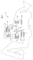
- FIG. 1 is a side elevational view of a work vehicle embodied, for example, as a backhoe loader;
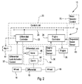
- FIG. 2 is a diagrammatic view showing a control unit for controlling a differential lock of a work vehicle
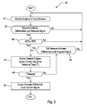
- FIG. 3 is a first control routine for use with the control unit of FIG. 2;
- FIG. 4 is a second control routine for use with the control unit of FIG. 2;
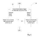
- FIG. 5 is a control routine integrating the control routines of FIGS. 3 and 4 for operator selectability.
- FIGS. 1 and 2 there is shown a vehicle 10 with a differential-lock control apparatus 12 comprising a differential lock 14 for locking a differential 16 so as to prevent rotation of wheels 18 coupled to the differential 16 at different speeds.
- the differential-lock control apparatus 12 is particularly useful with a wide variety of work vehicles such as, for example, the backhoe loader of FIG. 1.
- the apparatus 12 is configured to promote the integrity and longevity of the differential 16 should the vehicle operator attempt to activate the differential lock 14 when the wheels 18 are rotating at significantly different speeds.
- the apparatus 12 has a control unit 20 for controlling activation of the differential lock 14.
- the control unit 20 is an electronic unit which may comprise one or more controllers.
- the control unit 20 has at least two electronic controllers, a differential controller 22 responsible for control of the differential lock 14 and an engine controller 24 responsible for control of an engine 26, connected by a communication bus 28.
- the differential controller 22 and the engine controller 24 may be integrated as a single electronic controller.
- the control unit has a processor and a memory having stored therein instructions, which when executed by the processor, cause the processor to the perform the various operations of the control unit 20, such as, for example, either or both of the control routines shown in FIGS. 3 and 4 and discussed below.
- the control unit 20 is arranged for communication with an engine speed sensor 30, a differential-lock activation control 32, and the differential lock 14.
- the engine speed sensor 30 senses the actual engine speed ("AES" in drawings) of the engine 26 and outputs an engine speed signal representative of the actual engine speed to the control unit 20 or component thereof (e.g., the engine controller 24).
- the engine speed sensor 30 senses the rotation speed (e.g., revolutions per minute - rpm) of the crankshaft of the engine.
- the differential-lock activation control 32 may be, for example, an on/off switch located in a cab 34 of the vehicle 10 for actuation by the vehicle operator to request activation of the differential lock 14.
- the control 32 outputs an activate-differential-lock request signal to the control unit 20 or component thereof (e.g., the differential controller 22) upon such actuation of the control 32 by the operator.
- control unit 20 is adapted to: monitor output of the engine speed sensor 30 for the engine speed signal and output of the differential-lock activation control 32 for the activate-differential-lock request signal, determine from the engine speed signal if the actual engine speed is at least a threshold engine speed ("TES" in drawings) (e.g., 1500 rpm) in response to receipt of the activate-differential-lock request signal, allow for reduction of the actual engine speed to a desired engine speed (“DES” in drawings) (e.g., 1490 rpm) if the actual engine speed is at least the threshold engine speed in response to receipt of the activate-differential-lock request signal, and subsequently output an activate-differential-lock control signal to the differential lock 14 so as to command activation of the differential lock 14.
- TES threshold engine speed
- DES desired engine speed
- the threshold engine speed is selected based on its ability to cause a wheel 18 coupled to the differential 16 to slip (i.e., break traction with the underlying surface). Engine speeds at or exceeding the threshold engine speed are more likely to cause a wheel 18 to slip than engine speeds less than the threshold engine speed. When wheel slippage occurs, greater differences in wheel speeds between wheels 18 coupled to the differential 16 are more likely to occur, increasing the risk of differential damage upon differential lock activation. As such, the threshold engine speed is considered an adequate measure of whether to allow reduction of the actual engine speed to a desired engine speed, and thus reduction of the torque transfer through the drive train, before activation of the differential lock 14 upon actuation of the control 32.
- control unit 20 may be programmed to operate according to the control routine of either FIG. 3 or FIG. 4. Each control routine is discussed in turn.
- control routine 36 which may be incorporated into the control unit 20.
- the control routine 36 includes automatic speed control of the actual engine speed.
- control unit 20 monitors output of the engine speed sensor 30 for the engine speed signal. It also monitors output of the differential-lock activation control 32 for the activate-differential-lock request signal.
- control unit 20 determines whether it has received the activate-differential-lock request signal due to actuation of the control 32, representing that the operator has requested activation of the differential lock 14. If no, the control unit 20 continues to monitor output of the control 32 for the request signal and output of the engine speed sensor 30 for the engine speed signal in act 37. If yes, the control routine 36 advances to act 40.
- the control unit 20 determines from the engine speed signal if the actual engine speed (“AES") is at least the threshold engine speed (“TES") in response to receipt of the activate-differential-lock request signal. If no, the control unit 20 continues to monitor output of the control 32 for the request signal and output of the engine speed sensor 30 for the engine speed signal in act 37. If yes, the control routine 36 advances to act 42.
- AES actual engine speed
- TES threshold engine speed
- control unit 20 allows for reduction of the actual engine speed to a desired engine speed. It does so in control routine 36 by outputting a desired-engine-speed control signal commanding reduction of the actual engine speed to the desired engine speed, automatically effecting engine speed control.
- the desired-engine-speed control signal is outputted to the engine 26 so as to control fuel flow into the combustion chamber(s) thereof.
- the desired-engine-speed control signal may be sent to the fuel injector(s) to control the amount of fuel injected.
- the control unit 20 During output of the desired-engine-speed control signal, the control unit 20 overrides a requested engine speed requested by the operator with the desired engine speed so as to command engine operation at the desired engine speed instead of the requested engine speed.
- the control unit 20 monitors output of a requested speed sensor 43 (e.g., accelerator foot pedal position sensor or throttle position sensor) for a requested-engine-speed signal representative of the requested engine speed.
- the control unit 20 in effect, ignores the requested-engine-speed signal during outputting of the desired-engine-speed control signal.
- the desired-engine-speed control signal is outputted by the control unit 20 for a predetermined period of time ("T" in the drawings).
- T a predetermined period of time
- the duration of the predetermined period of time is established to allow sufficient time for the actual engine speed to reduce to the desired engine speed which is, for example, less than the threshold engine speed.
- the predetermined period of time may be determined by the control unit 20 based on the actual engine speed at the time of actuation of the control 32 by the operator, larger actual engine speeds resulting in larger time periods and smaller actual engine speeds resulting in smaller time periods.
- the control unit 20 may thus have a look-up table, equation, or other criteria stored in the memory thereof to determine the duration of the predetermined period of time.
- control unit 20 determines if the predetermined period of time has elapsed. If no, the control routine 36 advances to act 45. If yes, the control routine 36 advances to act 46.
- the control unit 20 confirms if the activate-differential-lock request is still present. In particular, the control unit 20 determines if it is still receiving the activate-differential-lock request signal. If yes, the control routine 36 advances to act 42, in which the control unit 20 continues to output the desired-engine-speed control signal. If no, the control routine 36 returns to act 37. This covers the situation where the operator requests activation of the differential lock 14 when the actual engine speed is at least the threshold engine speed but then ceases the request for activation of the differential lock 14 before elapse of the predetermined period of time.
- the control unit 20 outputs the activate-differential-lock control signal upon elapse of the predetermined period of time.
- This control signal commands activation of the differential lock 14.
- it does so by operating the solenoid portion of an electro-hydraulic valve 48 of the differential lock 14 so that hydraulic fluid is directed by the valve 48 to a differential lock clutch 50 (e.g., dog clutch) of the lock 14 to cause the clutch 50 to engage the differential 16 to cease relative rotation between the wheels 18.
- a differential lock clutch 50 e.g., dog clutch
- control unit 20 ceases to override the requested engine speed with the desired engine speed, allowing the actual engine speed to increase from the desired engine speed to the requested engine speed. This may be programmed into the control unit 20 so as to occur subsequent to activation of the differential lock 14 either while the control 32 is actuated or upon de-actuation of the control 32.
- the differential controller 22 monitors the output of the control 32 and the engine controller 24 monitors the output of the engine speed sensor 30.
- the engine controller 24 sends the actual engine speed to the differential controller 22 via the communication bus 28.
- the differential controller 22 performs acts 38 and 40 and, in act 42, outputs a signal representative of the desired engine speed to the engine controller 24 via the communication bus 28.
- the engine controller 24 then outputs the desired-engine-speed control signal to the engine 26.
- the differential controller 22 also performs the acts 44 and 46.
- control routine 52 which may be incorporated into the control unit 20 alternatively to, or in addition to, control routine 36.
- the control routine 52 includes manual speed control of the actual engine speed.
- control unit 20 monitors output of the engine speed sensor 30 for the engine speed signal. It also monitors output of the differential-lock activation control 32 for the activate-differential-lock request signal.
- control unit 20 determines whether it has received the activate-differential-lock request signal due to actuation of the control 32, representing that the operator has requested activation of the differential lock 14. If no, the control unit 20 continues to monitor output of the control 32 for the request signal and output of the engine speed sensor 30 for the engine speed signal in act 54. If yes, the control routine 52 advances to act 58.
- the control unit 20 determines from the engine speed signal if the actual engine speed (“AES") is at least the threshold engine speed (“TES") in response to receipt of the activate-differential-lock request signal. If no, the control unit 20 continues to monitor output of the control 32 for the request signal and output of the engine speed sensor 30 for the engine speed signal in act 54. If yes, the control routine 52 advances to act 60.
- AES actual engine speed
- TES threshold engine speed
- control unit 20 allows for reduction of the actual engine speed to a desired engine speed. It does so in control routine 52 by outputting an activate-alarm control signal commanding activation of an alarm 61 (e.g., audible, visual) in the cab 34 so as to indicate to the operator that the actual engine speed is at least as great as the threshold engine speed while waiting for manual reduction of the actual engine speed to the desired engine speed by the operator.
- an alarm 61 e.g., audible, visual
- the control unit 20 monitors output of the engine speed sensor 30 for the engine speed signal. It determines from the engine speed signal if the actual engine speed has reduced to the desired engine speed (i.e., if the actual engine speed is less than or equal to the desired engine speed) and outputs the activate-differential-lock control signal if the actual engine speed has reduced to the desired engine speed. If no, the control routine 52 advances to act 63. If yes, the control routine 52 advances to act 64.
- the control unit 20 confirms if the activate-differential-lock request is still present. In particular, the control unit 20 determines if it is still receiving the activate-differential-lock request signal. If yes, the control routine 52 advances to act 60, in which the control unit 20 continues to activate the alarm 61. If no, the control routine 52 returns to act 54. This covers the situation where the operator requests activation of the differential lock 14 when the actual engine speed is at least the threshold engine speed but then ceases the request for activation of the differential lock 14 before reduction of the actual engine speed to the desired engine speed.
- control unit 20 outputs the activate-differential-lock control signal commanding activation of the differential lock 14.
- it does so by operating the solenoid portion of the electro-hydraulic valve 48 so that hydraulic fluid is directed by the valve 48 to the clutch 50 to cause the clutch 50 to engage the differential 16 to cease relative rotation between the wheels 18.
- the differential controller 22 monitors the output of the control 32 and the engine controller 24 monitors the output of the engine speed sensor 30.
- the engine controller 24 sends the actual engine speed to the differential controller 22 via the communication bus 28.
- the differential controller 22 performs acts 56, 58, 60, 62, and 64 while the engine controller 24 continues to control the actual engine speed in response to the requested-engine-speed signal generated in response to operation of the vehicle speed control by the operator.
- control routine 66 which may be programmed into the control unit 20.
- the control routine 66 allows the operator to select either control routine 36 with its automatic engine speed control feature or control routine 52 with its manual engine speed control feature by actuation of a mode selector control 70 located, for example, in the cab 34 (FIGS. 1 and 2).
- the control unit 20 monitors output of the mode selector control 70 (FIGS. 1 and 2) for a mode-selection signal representative of an operator selection between the different control modes for the differential lock, i.e., between the automatic engine speed control mode (control routine 36) or the manual engine speed control mode (control routine 52). If the automatic engine speed control mode is selected, the control routine 66 advances to act 71 in which the ontrol unit 20 performs the control routine 36. If the manual engine speed control mode is selected, the control routine 66 advances to act 72 in which the control unit 20 performs the control routine 52. As such, the operator may select whichever differential-lock control mode is preferred.
Landscapes
- Engineering & Computer Science (AREA)
- Chemical & Material Sciences (AREA)
- Combustion & Propulsion (AREA)
- Transportation (AREA)
- Mechanical Engineering (AREA)
- Control Of Fluid Gearings (AREA)
- Control Of Vehicle Engines Or Engines For Specific Uses (AREA)
Abstract
Description
- The present invention relates to control of a differential lock.
- A differential may be used on a vehicle to transmit power to the wheels while allowing them to rotate at different speeds. A differential lock may be associated with the differential such that, when activated, the differential lock disallows the wheels to rotate at different speeds in order to prevent spinning of the wheels due to traction loss. A differential-lock activation switch onboard the vehicle may be switched on by the vehicle operator to activate the differential lock. However, activation of the differential lock when the wheels are rotating at significantly different speeds may compromise the differential.
- It is therefore an object of the present invention to overcome the disadvantages mentioned above.
- According to the present disclosure, there is provided a differential-lock control apparatus. The differential-lock control apparatus comprises an engine speed sensor, a differential-lock activation control, a differential lock, and a control unit arranged for communication with the engine speed sensor, the differential-lock activation control, and the differential lock. The control unit is adapted to: monitor output of the engine speed sensor for an engine speed signal and output of the differential-lock activation control for an activate-differential-lock request signal, determine from the engine speed signal if an actual engine speed is at least a threshold engine speed in response to receipt of the activate-differential-lock request signal, allow for reduction of the actual engine speed to a desired engine speed if the actual engine speed is at least the threshold engine speed in response to receipt of the activate-differential-lock request signal, and subsequently output an activate-differential-lock control signal to the differential lock so as to command activation of the differential lock.
- Reduction of the actual engine speed before activation of the differential lock is useful for reducing what may otherwise be a potentially differential-damaging difference in wheel speeds. As such, the control unit is configured so as to promote the integrity and longevity of the differential. With this system, an operator would not need to remember to slow or stop the vehicle before activating the differential lock. An associated method is disclosed.
- In a first embodiment, the control unit commands reduction of the actual engine speed if the actual engine speed is at least as great as the threshold engine speed when the differential-lock activation control is actuated. The control unit does so by outputting a desired-engine-speed control signal so as to cause the engine to reduce its speed to the desired engine speed, which is, for example, below the threshold engine speed. The control unit outputs this signal for a predetermined period of time, this time period being sufficient for reduction of the actual engine speed to the desired engine speed. Upon elapse of the predetermined period of time, the control unit outputs the activate-differential-lock control signal activating the differential lock so as to lock the differential ceasing any relative rotation between the wheels so that rotation of the wheels will be in unison. Thereafter, the control unit may operate so as to increase the actual engine speed to the requested engine speed.
- In a second embodiment, if the actual engine speed is at least as great as the threshold engine speed when the differential-lock activation control is actuated, the control unit outputs an activate-alarm control signal activating an alarm so as to indicate to the vehicle operator that the actual engine speed is at least as great as the threshold engine speed. The control unit then waits for the operator to reduce the actual engine speed. While waiting, it continues to monitor the actual engine speed and determines if the actual engine speed has reduced to the desired engine speed. If the control unit determines that the actual engine speed has reduced to the desired engine speed, the control unit outputs the activate-differential-lock control signal activating the differential lock so as to lock the differential ceasing any relative rotation between the wheels so that rotation of the wheels will be in unison.
- The above and other features will become apparent from the following description and the attached drawings.
- The control unit might be adapted to output a desired-engine-speed control signal commanding reduction of the actual engine speed to the desired engine speed.
- The control unit might be adapted to output the desired-engine-speed control signal for a predetermined period of time, and adapted to output the activate-differential-lock control signal upon elapse of the predetermined period of time.
- Furthermore, the control unit might be adapted to determine the duration of the predetermined period of time based on the actual engine speed at the time of actuation of the differential-lock activation control by an operator.
- The control unit preferably is adapted to output the desired-engine-speed control signal such that the desired engine speed is less than the threshold engine speed.
- The differential-lock control apparatus could comprise a speed input device. The control unit could be adapted to monitor output of the speed input device for a requested engine speed signal representative of a requested engine speed, and could be adapted to override the requested engine speed with the desired engine speed so as to command engine operation at the desired engine speed instead of the requested engine speed.
- Alternatively or additionally, the control unit is adapted to determine if the actual engine speed has reduced to the desired engine speed and output the activate-differential-lock control signal if the actual engine speed has reduced to the desired engine speed.
- The differential-lock control apparatus could comprise an alarm. The control unit could be adapted to output an activate-alarm control signal commanding activation of the alarm so as to indicate that the actual engine speed is at least as great as the threshold engine speed while waiting for manual reduction of the actual engine speed to the desired engine speed.
- The differential-lock control apparatus preferably comprises a mode selector control operable by an operator to select between different control modes for the differential lock. The control unit could be adapted to monitor output of the mode selector control for a mode-selection signal.
- According to
claim 10, a method according to the invention is provided, the method comprises: - monitoring an engine speed signal and for an activate-differential-lock request signal,
- determining from the engine speed signal if an actual engine speed is at least as great as a threshold engine speed in response to receipt of the activate-differential-lock request signal,
- allowing for reduction of the actual engine speed to a desired engine speed if the actual engine speed is at least as great as the threshold engine speed in response to receipt of the activate-differential-lock request signal, and
- subsequently outputting an activate-differential-lock control signal commanding activation of a differential lock.
- The method preferably is adapted to control or operate a differential-lock control apparatus according to one of the
claims 1 to 9. - The monitoring could comprise monitoring output of an engine speed sensor for the engine speed signal and output of a differential-lock activation control for the activate-differential-lock request signal.
- The allowing could comprise outputting a desired-engine-speed control signal commanding reduction of the actual engine speed to the desired engine speed.
- Outputting the desired-engine-speed control signal could comprise outputting the desired-engine-speed control signal for a predetermined period of time. Alternatively or additionally outputting the activate-differential-lock control signal could comprise outputting the activate-differential-lock control signal upon elapse of the predetermined period of time.
- The allowing could comprise determining the duration of the predetermined period of time based on the actual engine speed at the time of actuation of a differential-lock activation control by an operator.
- Outputting the desired-engine-speed control signal could comprise outputting the desired-engine-speed control signal such that the desired engine speed is less than the threshold engine speed.
- The method could comprise monitoring a requested engine speed signal representative of a requested engine speed, wherein outputting the desired-engine-speed control signal comprises overriding the requested engine speed with the desired engine speed so as to command engine operation at the desired engine speed instead of the requested engine speed.
- The allowing could comprise determining if the actual engine speed has reduced to the desired engine speed, and the outputting could comprise outputting the activate-differential-lock control signal if the actual engine speed has reduced to the desired engine speed.
- The allowing could comprise outputting an activate-alarm control signal commanding activation of an alarm so as to indicate that the actual engine speed is at least as great as the threshold engine speed while waiting for manual reduction of the actual engine speed to the desired engine speed.
- The method could comprise the step of monitoring for a mode-selection signal representative of an operator selection between different control modes for the differential lock.
- For a complete understanding of the objects, techniques, and structure of the invention reference should be made to the following detailed description and accompanying drawings, wherein:
- FIG. 1 is a side elevational view of a work vehicle embodied, for example, as a backhoe loader;
- FIG. 2 is a diagrammatic view showing a control unit for controlling a differential lock of a work vehicle;
- FIG. 3 is a first control routine for use with the control unit of FIG. 2;
- FIG. 4 is a second control routine for use with the control unit of FIG. 2; and
- FIG. 5 is a control routine integrating the control routines of FIGS. 3 and 4 for operator selectability.
- Referring to FIGS. 1 and 2, there is shown a
vehicle 10 with a differential-lock control apparatus 12 comprising adifferential lock 14 for locking adifferential 16 so as to prevent rotation ofwheels 18 coupled to thedifferential 16 at different speeds. The differential-lock control apparatus 12 is particularly useful with a wide variety of work vehicles such as, for example, the backhoe loader of FIG. 1. Theapparatus 12 is configured to promote the integrity and longevity of thedifferential 16 should the vehicle operator attempt to activate thedifferential lock 14 when thewheels 18 are rotating at significantly different speeds. - The
apparatus 12 has acontrol unit 20 for controlling activation of thedifferential lock 14. Thecontrol unit 20 is an electronic unit which may comprise one or more controllers. Illustratively, thecontrol unit 20 has at least two electronic controllers, adifferential controller 22 responsible for control of thedifferential lock 14 and anengine controller 24 responsible for control of anengine 26, connected by acommunication bus 28. It is to be understood that thedifferential controller 22 and theengine controller 24 may be integrated as a single electronic controller. In either case, the control unit has a processor and a memory having stored therein instructions, which when executed by the processor, cause the processor to the perform the various operations of thecontrol unit 20, such as, for example, either or both of the control routines shown in FIGS. 3 and 4 and discussed below. - The
control unit 20 is arranged for communication with anengine speed sensor 30, a differential-lock activation control 32, and thedifferential lock 14. Theengine speed sensor 30 senses the actual engine speed ("AES" in drawings) of theengine 26 and outputs an engine speed signal representative of the actual engine speed to thecontrol unit 20 or component thereof (e.g., the engine controller 24). Exemplarily, theengine speed sensor 30 senses the rotation speed (e.g., revolutions per minute - rpm) of the crankshaft of the engine. The differential-lock activation control 32 may be, for example, an on/off switch located in a cab 34 of thevehicle 10 for actuation by the vehicle operator to request activation of thedifferential lock 14. Thecontrol 32 outputs an activate-differential-lock request signal to thecontrol unit 20 or component thereof (e.g., the differential controller 22) upon such actuation of thecontrol 32 by the operator. - Generally speaking, the
control unit 20 is adapted to: monitor output of theengine speed sensor 30 for the engine speed signal and output of the differential-lock activation control 32 for the activate-differential-lock request signal, determine from the engine speed signal if the actual engine speed is at least a threshold engine speed ("TES" in drawings) (e.g., 1500 rpm) in response to receipt of the activate-differential-lock request signal, allow for reduction of the actual engine speed to a desired engine speed ("DES" in drawings) (e.g., 1490 rpm) if the actual engine speed is at least the threshold engine speed in response to receipt of the activate-differential-lock request signal, and subsequently output an activate-differential-lock control signal to thedifferential lock 14 so as to command activation of thedifferential lock 14. - The threshold engine speed is selected based on its ability to cause a
wheel 18 coupled to the differential 16 to slip (i.e., break traction with the underlying surface). Engine speeds at or exceeding the threshold engine speed are more likely to cause awheel 18 to slip than engine speeds less than the threshold engine speed. When wheel slippage occurs, greater differences in wheel speeds betweenwheels 18 coupled to the differential 16 are more likely to occur, increasing the risk of differential damage upon differential lock activation. As such, the threshold engine speed is considered an adequate measure of whether to allow reduction of the actual engine speed to a desired engine speed, and thus reduction of the torque transfer through the drive train, before activation of thedifferential lock 14 upon actuation of thecontrol 32. - As mentioned above, the
control unit 20 may be programmed to operate according to the control routine of either FIG. 3 or FIG. 4. Each control routine is discussed in turn. - Referring to FIG. 3, there is shown
control routine 36 which may be incorporated into thecontrol unit 20. Thecontrol routine 36 includes automatic speed control of the actual engine speed. - In
act 37 of thecontrol routine 36, thecontrol unit 20 monitors output of theengine speed sensor 30 for the engine speed signal. It also monitors output of the differential-lock activation control 32 for the activate-differential-lock request signal. - In
act 38, thecontrol unit 20 determines whether it has received the activate-differential-lock request signal due to actuation of thecontrol 32, representing that the operator has requested activation of thedifferential lock 14. If no, thecontrol unit 20 continues to monitor output of thecontrol 32 for the request signal and output of theengine speed sensor 30 for the engine speed signal inact 37. If yes, the control routine 36 advances to act 40. - In
act 40, thecontrol unit 20 determines from the engine speed signal if the actual engine speed ("AES") is at least the threshold engine speed ("TES") in response to receipt of the activate-differential-lock request signal. If no, thecontrol unit 20 continues to monitor output of thecontrol 32 for the request signal and output of theengine speed sensor 30 for the engine speed signal inact 37. If yes, the control routine 36 advances to act 42. - In
act 42, thecontrol unit 20 allows for reduction of the actual engine speed to a desired engine speed. It does so incontrol routine 36 by outputting a desired-engine-speed control signal commanding reduction of the actual engine speed to the desired engine speed, automatically effecting engine speed control.
Exemplarily, the desired-engine-speed control signal is outputted to theengine 26 so as to control fuel flow into the combustion chamber(s) thereof. As such, the desired-engine-speed control signal may be sent to the fuel injector(s) to control the amount of fuel injected. - During output of the desired-engine-speed control signal, the
control unit 20 overrides a requested engine speed requested by the operator with the desired engine speed so as to command engine operation at the desired engine speed instead of the requested engine speed. Thecontrol unit 20 monitors output of a requested speed sensor 43 (e.g., accelerator foot pedal position sensor or throttle position sensor) for a requested-engine-speed signal representative of the requested engine speed. Thecontrol unit 20, in effect, ignores the requested-engine-speed signal during outputting of the desired-engine-speed control signal. - The desired-engine-speed control signal is outputted by the
control unit 20 for a predetermined period of time ("T" in the drawings). The duration of the predetermined period of time is established to allow sufficient time for the actual engine speed to reduce to the desired engine speed which is, for example, less than the threshold engine speed. As such, the predetermined period of time may be determined by thecontrol unit 20 based on the actual engine speed at the time of actuation of thecontrol 32 by the operator, larger actual engine speeds resulting in larger time periods and smaller actual engine speeds resulting in smaller time periods. Thecontrol unit 20 may thus have a look-up table, equation, or other criteria stored in the memory thereof to determine the duration of the predetermined period of time. - In
act 44, thecontrol unit 20 determines if the predetermined period of time has elapsed. If no, the control routine 36 advances to act 45. If yes, the control routine 36 advances to act 46. - In
act 45, thecontrol unit 20 confirms if the activate-differential-lock request is still present. In particular, thecontrol unit 20 determines if it is still receiving the activate-differential-lock request signal. If yes, the control routine 36 advances to act 42, in which thecontrol unit 20 continues to output the desired-engine-speed control signal. If no, thecontrol routine 36 returns to act 37. This covers the situation where the operator requests activation of thedifferential lock 14 when the actual engine speed is at least the threshold engine speed but then ceases the request for activation of thedifferential lock 14 before elapse of the predetermined period of time. - In
act 46, thecontrol unit 20 outputs the activate-differential-lock control signal upon elapse of the predetermined period of time. This control signal commands activation of thedifferential lock 14. Exemplarily, it does so by operating the solenoid portion of an electro-hydraulic valve 48 of thedifferential lock 14 so that hydraulic fluid is directed by thevalve 48 to a differential lock clutch 50 (e.g., dog clutch) of thelock 14 to cause the clutch 50 to engage the differential 16 to cease relative rotation between thewheels 18. - At some point thereafter, the
control unit 20 ceases to override the requested engine speed with the desired engine speed, allowing the actual engine speed to increase from the desired engine speed to the requested engine speed. This may be programmed into thecontrol unit 20 so as to occur subsequent to activation of thedifferential lock 14 either while thecontrol 32 is actuated or upon de-actuation of thecontrol 32. - In the case where the
control unit 20 hasseparate controllers differential controller 22 monitors the output of thecontrol 32 and theengine controller 24 monitors the output of theengine speed sensor 30. Theengine controller 24 sends the actual engine speed to thedifferential controller 22 via thecommunication bus 28. Thedifferential controller 22 performsacts act 42, outputs a signal representative of the desired engine speed to theengine controller 24 via thecommunication bus 28. Theengine controller 24 then outputs the desired-engine-speed control signal to theengine 26. Thedifferential controller 22 also performs theacts - Referring to FIG. 4, there is shown
control routine 52 which may be incorporated into thecontrol unit 20 alternatively to, or in addition to, controlroutine 36. Thecontrol routine 52 includes manual speed control of the actual engine speed. - In
act 54 of thecontrol routine 52, thecontrol unit 20 monitors output of theengine speed sensor 30 for the engine speed signal. It also monitors output of the differential-lock activation control 32 for the activate-differential-lock request signal. - In
act 56, thecontrol unit 20 determines whether it has received the activate-differential-lock request signal due to actuation of thecontrol 32, representing that the operator has requested activation of thedifferential lock 14. If no, thecontrol unit 20 continues to monitor output of thecontrol 32 for the request signal and output of theengine speed sensor 30 for the engine speed signal inact 54. If yes, the control routine 52 advances to act 58. - In
act 58, thecontrol unit 20 determines from the engine speed signal if the actual engine speed ("AES") is at least the threshold engine speed ("TES") in response to receipt of the activate-differential-lock request signal. If no, thecontrol unit 20 continues to monitor output of thecontrol 32 for the request signal and output of theengine speed sensor 30 for the engine speed signal inact 54. If yes, the control routine 52 advances to act 60. - In
act 60, thecontrol unit 20 allows for reduction of the actual engine speed to a desired engine speed. It does so incontrol routine 52 by outputting an activate-alarm control signal commanding activation of an alarm 61 (e.g., audible, visual) in the cab 34 so as to indicate to the operator that the actual engine speed is at least as great as the threshold engine speed while waiting for manual reduction of the actual engine speed to the desired engine speed by the operator. - In
act 62, while waiting, thecontrol unit 20 monitors output of theengine speed sensor 30 for the engine speed signal. It determines from the engine speed signal if the actual engine speed has reduced to the desired engine speed (i.e., if the actual engine speed is less than or equal to the desired engine speed) and outputs the activate-differential-lock control signal if the actual engine speed has reduced to the desired engine speed. If no, the control routine 52 advances to act 63. If yes, the control routine 52 advances to act 64. - In
act 63, thecontrol unit 20 confirms if the activate-differential-lock request is still present. In particular, thecontrol unit 20 determines if it is still receiving the activate-differential-lock request signal. If yes, the control routine 52 advances to act 60, in which thecontrol unit 20 continues to activate thealarm 61. If no, thecontrol routine 52 returns to act 54. This covers the situation where the operator requests activation of thedifferential lock 14 when the actual engine speed is at least the threshold engine speed but then ceases the request for activation of thedifferential lock 14 before reduction of the actual engine speed to the desired engine speed. - In
act 64, thecontrol unit 20 outputs the activate-differential-lock control signal commanding activation of thedifferential lock 14. Exemplarily, it does so by operating the solenoid portion of the electro-hydraulic valve 48 so that hydraulic fluid is directed by thevalve 48 to the clutch 50 to cause the clutch 50 to engage the differential 16 to cease relative rotation between thewheels 18. - In the case where the
control unit 20 hasseparate controllers differential controller 22 monitors the output of thecontrol 32 and theengine controller 24 monitors the output of theengine speed sensor 30. Theengine controller 24 sends the actual engine speed to thedifferential controller 22 via thecommunication bus 28. Thedifferential controller 22 performsacts engine controller 24 continues to control the actual engine speed in response to the requested-engine-speed signal generated in response to operation of the vehicle speed control by the operator. - Referring to FIG. 5, there is shown a
control routine 66 which may be programmed into thecontrol unit 20. Thecontrol routine 66 allows the operator to select either control routine 36 with its automatic engine speed control feature or control routine 52 with its manual engine speed control feature by actuation of amode selector control 70 located, for example, in the cab 34 (FIGS. 1 and 2). - In
act 68 of thecontrol routine 66, thecontrol unit 20 monitors output of the mode selector control 70 (FIGS. 1 and 2) for a mode-selection signal representative of an operator selection between the different control modes for the differential lock, i.e., between the automatic engine speed control mode (control routine 36) or the manual engine speed control mode (control routine 52). If the automatic engine speed control mode is selected, the control routine 66 advances to act 71 in which theontrol unit 20 performs thecontrol routine 36. If the manual engine speed control mode is selected, the control routine 66 advances to act 72 in which thecontrol unit 20 performs thecontrol routine 52. As such, the operator may select whichever differential-lock control mode is preferred. - While the disclosure has been illustrated and described in detail in the drawings and foregoing description, such illustration and description is to be considered as exemplary and not restrictive in character, it being understood that illustrative embodiments have been shown and described and that all changes and modifications that come within the spirit of the disclosure are desired to be protected. It will be noted that alternative embodiments of the present disclosure may not include all of the features described yet still benefit from at least some of the advantages of such features. Those of ordinary skill in the art may readily devise their own implementations that incorporate one or more of the features of the present disclosure and fall within the scope of the present invention as defined by the appended claims.
Claims (19)
- A differential-lock control apparatus, comprising:an engine speed sensor (30),a differential-lock activation control (32),a differential lock (14), anda control unit (20) arranged for communication with the engine speed sensor (30), the differential-lock activation control (32), and the differential lock (14), the control unit (20) adapted to:monitor output of the engine speed sensor (30) for an engine speed signal and output of the differential-lock activation control (32) for an activate-differential-lock request signal,determine from the engine speed signal if an actual engine speed (AES) is at least a threshold engine speed (TES) in response to receipt of the activate-differential-lock request signal,allow for reduction of the actual engine speed to a desired engine speed (DES) if the actual engine speed is at least the threshold engine speed (TES) in response to receipt of the activate-differential-lock request signal, andsubsequently output an activate-differential-lock control signal to the differential lock (14) so as to command activation of the differential lock (14).
- The differential-lock control apparatus of claim 1, wherein the control unit (20) is adapted to output a desired-engine-speed control signal commanding reduction of the actual engine speed (AES) to the desired engine speed (DES).
- The differential-lock control apparatus of claim 2, wherein the control unit (20) is adapted to output the desired-engine-speed control signal for a predetermined period of time (T), and adapted to output the activate-differential-lock control signal upon elapse of the predetermined period of time (T).
- The differential-lock control apparatus of claim 3, wherein the control unit (20) is adapted to determine the duration of the predetermined period of time (T) based on the actual engine speed (AES) at the time of actuation of the differential-lock activation control (32) by an operator.
- The differential-lock control apparatus of one of the claims 2 to 4, wherein the control unit (20) is adapted to output the desired-engine-speed control signal such that the desired engine speed (DES) is less than the threshold engine speed (TES).
- The differential-lock control apparatus of claim 2, comprising a speed input device, wherein the control unit (20) is adapted to monitor output of the speed input device for a requested engine speed signal representative of a requested engine speed, and adapted to override the requested engine speed with the desired engine speed (DES) so as to command engine operation at the desired engine speed (DES) instead of the requested engine speed.
- The differential-lock control apparatus of one of the claims 1 to 6, wherein the control unit (20) is adapted to determine if the actual engine speed (AES) has reduced to the desired engine speed (DES) and output the activate-differential-lock control signal if the actual engine speed (AES) has reduced to the desired engine speed (DES).
- The differential-lock control apparatus of claim 7, comprising an alarm (61), wherein the control unit (20) is adapted to output an activate-alarm control signal commanding activation of the alarm (61) so as to indicate that the actual engine speed (AES) is at least as great as the threshold engine speed (TES) while waiting for manual reduction of the actual engine speed (AES) to the desired engine speed (DES).
- The differential-lock control apparatus of one of the claims 1 to 8, comprising a mode selector control (70) operable by an operator to select between different control modes for the differential lock (14), wherein the control unit (20) is adapted to monitor output of the mode selector control (70) for a mode-selection signal.
- A method, especially to operate a differential-lock control apparatus according to one of the claims 1 to 9, the method comprising:monitoring an engine speed signal and for an activate-differential-lock request signal,determining from the engine speed signal if an actual engine speed (AES) is at least as great as a threshold engine speed (TES) in response to receipt of the activate-differential-lock request signal,allowing for reduction of the actual engine speed (AES) to a desired engine speed (DES) if the actual engine speed (AES) is at least as great as the threshold engine speed (TES) in response to receipt of the activate-differential-lock request signal, andsubsequently outputting an activate-differential-lock control signal commanding activation of a differential lock (14).
- The method of claim 10, wherein the monitoring comprises monitoring output of an engine speed sensor (30) for the engine speed signal and output of a differential-lock activation control (32) for the activate-differential-lock request signal.
- The method of claim 10 or 11, wherein the allowing comprises outputting a desired-engine-speed control signal commanding reduction of the actual engine speed (AES) to the desired engine speed (DES).
- The method of claim 12, wherein outputting the desired-engine-speed control signal comprises outputting the desired-engine-speed control signal for a predetermined period of time (T), and outputting the activate-differential-lock control signal comprises outputting the activate-differential-lock control signal upon elapse of the predetermined period of time (T).
- The method of claim 13, wherein the allowing comprises determining the duration of the predetermined period of time (T) based on the actual engine speed (AES) at the time of actuation of a differential-lock activation control (32) by an operator.
- The method of claim 14, wherein outputting the desired-engine-speed control signal comprises outputting the desired-engine-speed control signal such that the desired engine speed (DES) is less than the threshold engine speed (TES).
- The method of one of the claims 12 to 15, comprising monitoring a requested engine speed signal representative of a requested engine speed, wherein outputting the desired-engine-speed control signal comprises overriding the requested engine speed with the desired engine speed (DES) so as to command engine operation at the desired engine speed (DES) instead of the requested engine speed.
- The method of one of the claims 10 to 16, wherein the allowing comprises determining if the actual engine speed (AES) has reduced to the desired engine speed (DES), and the outputting comprises outputting the activate-differential-lock control signal if the actual engine speed (AES) has reduced to the desired engine speed (DES).
- The method of claim 17, wherein the allowing comprises outputting an activate-alarm control signal commanding activation of an alarm (61) so as to indicate that the actual engine speed (AES) is at least as great as the threshold engine speed (TES) while waiting for manual reduction of the actual engine speed (AES) to the desired engine speed (DES).
- The method of one of the claims 10 to 18, monitoring for a mode-selection signal representative of an operator selection between different control modes for the differential lock (14).
Applications Claiming Priority (1)
| Application Number | Priority Date | Filing Date | Title |
|---|---|---|---|
| US11/541,839 US7666116B2 (en) | 2006-10-02 | 2006-10-02 | Method and apparatus for differential lock control |
Publications (2)
| Publication Number | Publication Date |
|---|---|
| EP1908620A1 true EP1908620A1 (en) | 2008-04-09 |
| EP1908620B1 EP1908620B1 (en) | 2010-10-27 |
Family
ID=38894098
Family Applications (1)
| Application Number | Title | Priority Date | Filing Date |
|---|---|---|---|
| EP07117072A Not-in-force EP1908620B1 (en) | 2006-10-02 | 2007-09-24 | Method and apparatus for differential lock control |
Country Status (5)
| Country | Link |
|---|---|
| US (1) | US7666116B2 (en) |
| EP (1) | EP1908620B1 (en) |
| CN (1) | CN101158394B (en) |
| CA (1) | CA2600825A1 (en) |
| DE (1) | DE602007010068D1 (en) |
Families Citing this family (9)
| Publication number | Priority date | Publication date | Assignee | Title |
|---|---|---|---|---|
| DE102009001492B4 (en) * | 2009-03-11 | 2022-04-28 | Zf Friedrichshafen Ag | Procedure for activating a differential lock |
| US9605740B2 (en) * | 2009-10-01 | 2017-03-28 | Ford Global Technologies, Llc | Control of an electronic locking differential |
| US20110269595A1 (en) | 2010-04-30 | 2011-11-03 | American Axle & Manufacturing Inc. | Control strategy for operating a locking differential |
| JP5517211B2 (en) * | 2010-12-10 | 2014-06-11 | 本田技研工業株式会社 | Front wheel differential lock control device for saddle-ride type four-wheel vehicle |
| US8790217B1 (en) | 2013-03-01 | 2014-07-29 | Honda Motor Co., Ltd. | Vehicles including differential lock controller and methods |
| CN103496634A (en) * | 2013-09-18 | 2014-01-08 | 徐州重型机械有限公司 | Control method and system for switching operating modes of differential lock, and wheel crane |
| US9440656B2 (en) | 2014-12-03 | 2016-09-13 | Caterpillar Inc. | Torque control for dog clutch differential engagement |
| JP2023062691A (en) * | 2021-10-21 | 2023-05-08 | 三菱電機株式会社 | Vehicle control device |
| CN114198478B (en) * | 2021-12-14 | 2023-09-22 | 三一专用汽车有限责任公司 | Differential lock control method, controller thereof and engineering vehicle |
Citations (3)
| Publication number | Priority date | Publication date | Assignee | Title |
|---|---|---|---|---|
| WO1993001065A1 (en) | 1991-07-01 | 1993-01-21 | Saab-Scania Aktiebolag | Arrangement for controlling the differential lock in a motor vehicle |
| JP2000064870A (en) * | 1998-08-25 | 2000-02-29 | Iseki & Co Ltd | Engine rotation control device of agricultural work machine |
| US20020070066A1 (en) * | 2000-12-07 | 2002-06-13 | Kazuo Nakamura | Differential locking control system |
Family Cites Families (10)
| Publication number | Priority date | Publication date | Assignee | Title |
|---|---|---|---|---|
| US4549448A (en) | 1983-06-13 | 1985-10-29 | Deere & Company | Differential lock control system responsive to a plurality of vehicle parameters |
| US4570509A (en) | 1983-06-13 | 1986-02-18 | Deere & Company | Differential lock control system responsive to steering and/or braking action to unlock differential |
| US4523494A (en) | 1983-06-13 | 1985-06-18 | Deere & Company | Steering pressure responsive differential lock control system |
| US4559847A (en) | 1983-06-13 | 1985-12-24 | Deere & Company | Steering pressure-responsive differential lock control system |
| US4867010A (en) | 1988-07-28 | 1989-09-19 | Deere & Company | Differential lock with non-rotating hydraulically actuated piston |
| US5026335A (en) | 1989-03-03 | 1991-06-25 | Deere & Company | Downshifting work vehicle using differential lock switch |
| US6174255B1 (en) | 1999-10-05 | 2001-01-16 | Deere & Company | Differential lock control system for articulated work vehicle |
| SE524538C2 (en) * | 2002-02-19 | 2004-08-24 | Volvo Lastvagnar Ab | Device for controlling outgoing engine torque in trucks equipped with differential locks |
| US6640850B1 (en) | 2002-07-11 | 2003-11-04 | Caterpillar Inc | Tree harvesting apparatus |
| US7680571B2 (en) * | 2006-09-11 | 2010-03-16 | Gm Global Technology Operations, Inc. | Vehicle differential score protection |
-
2006
- 2006-10-02 US US11/541,839 patent/US7666116B2/en active Active
-
2007
- 2007-09-06 CA CA002600825A patent/CA2600825A1/en not_active Abandoned
- 2007-09-24 EP EP07117072A patent/EP1908620B1/en not_active Not-in-force
- 2007-09-24 DE DE602007010068T patent/DE602007010068D1/en active Active
- 2007-09-25 CN CN2007101806053A patent/CN101158394B/en not_active Expired - Fee Related
Patent Citations (3)
| Publication number | Priority date | Publication date | Assignee | Title |
|---|---|---|---|---|
| WO1993001065A1 (en) | 1991-07-01 | 1993-01-21 | Saab-Scania Aktiebolag | Arrangement for controlling the differential lock in a motor vehicle |
| JP2000064870A (en) * | 1998-08-25 | 2000-02-29 | Iseki & Co Ltd | Engine rotation control device of agricultural work machine |
| US20020070066A1 (en) * | 2000-12-07 | 2002-06-13 | Kazuo Nakamura | Differential locking control system |
Also Published As
| Publication number | Publication date |
|---|---|
| CA2600825A1 (en) | 2008-04-02 |
| EP1908620B1 (en) | 2010-10-27 |
| US20080081731A1 (en) | 2008-04-03 |
| CN101158394A (en) | 2008-04-09 |
| DE602007010068D1 (en) | 2010-12-09 |
| CN101158394B (en) | 2012-07-11 |
| US7666116B2 (en) | 2010-02-23 |
Similar Documents
| Publication | Publication Date | Title |
|---|---|---|
| EP1908620A1 (en) | Method and apparatus for differential lock control | |
| US8666630B2 (en) | Method for increasing active duration time of an automatic freewheeling function in a vehicle | |
| US10753460B2 (en) | Electronic control of a transmission | |
| KR900000394B1 (en) | Control method and device of automatic clutch | |
| EP1225362A2 (en) | Method of controlling heat buildup in a clutch | |
| US6508739B1 (en) | System for protecting drive line components from excessive engine inertial forces | |
| US6250448B1 (en) | Motor vehicle with an automatically actuated clutch | |
| CN102770644A (en) | Wheel loader | |
| US6142909A (en) | Device for controlling a starting process of a motor vehicle | |
| KR100852991B1 (en) | Start-off prevention system and brake control method when braking the work machine | |
| US7258650B2 (en) | Systems and methods for controlling a powertrain | |
| EP2066519B1 (en) | .an automatic disengaging/engaging method of a clutch dependent power take-off | |
| US9194487B2 (en) | System and method for automatically downshifting an automatic transmission with alternate forward launch gear | |
| US6148975A (en) | Vehicle transmission system including clutch control to eliminate neutral idle gear rattle | |
| US7377827B1 (en) | Marine propulsion shift control | |
| SE1150787A1 (en) | Device and method for controlling the propulsion of a motor vehicle | |
| CN108291638B (en) | Recreational vehicle and method of operating the same | |
| US20190135245A1 (en) | Method of operating the power train of a vehicle | |
| US20040064224A1 (en) | Low speed shift strategy for marine engines | |
| JP2002308077A (en) | Braking control device for vehicles with automatic clutch | |
| JPH0473005B2 (en) | ||
| KR20080005542A (en) | Method and apparatus for controlling stop circuit of automatic transmission | |
| JPH10259745A (en) | Device for reducing shock in starting vehicle | |
| JPH0573354U (en) | Lockup control device for torque converter | |
| JPS6299227A (en) | Method of controlling clutch in vehicle mounted with automatic clutch |
Legal Events
| Date | Code | Title | Description |
|---|---|---|---|
| PUAI | Public reference made under article 153(3) epc to a published international application that has entered the european phase |
Free format text: ORIGINAL CODE: 0009012 |
|
| AK | Designated contracting states |
Kind code of ref document: A1 Designated state(s): AT BE BG CH CY CZ DE DK EE ES FI FR GB GR HU IE IS IT LI LT LU LV MC MT NL PL PT RO SE SI SK TR |
|
| AX | Request for extension of the european patent |
Extension state: AL BA HR MK RS |
|
| 17P | Request for examination filed |
Effective date: 20081009 |
|
| 17Q | First examination report despatched |
Effective date: 20081114 |
|
| AKX | Designation fees paid |
Designated state(s): DE GB SE |
|
| GRAP | Despatch of communication of intention to grant a patent |
Free format text: ORIGINAL CODE: EPIDOSNIGR1 |
|
| GRAS | Grant fee paid |
Free format text: ORIGINAL CODE: EPIDOSNIGR3 |
|
| GRAA | (expected) grant |
Free format text: ORIGINAL CODE: 0009210 |
|
| AK | Designated contracting states |
Kind code of ref document: B1 Designated state(s): DE GB SE |
|
| REG | Reference to a national code |
Ref country code: GB Ref legal event code: FG4D |
|
| REF | Corresponds to: |
Ref document number: 602007010068 Country of ref document: DE Date of ref document: 20101209 Kind code of ref document: P |
|
| REG | Reference to a national code |
Ref country code: SE Ref legal event code: TRGR |
|
| PLBE | No opposition filed within time limit |
Free format text: ORIGINAL CODE: 0009261 |
|
| STAA | Information on the status of an ep patent application or granted ep patent |
Free format text: STATUS: NO OPPOSITION FILED WITHIN TIME LIMIT |
|
| 26N | No opposition filed |
Effective date: 20110728 |
|
| REG | Reference to a national code |
Ref country code: DE Ref legal event code: R097 Ref document number: 602007010068 Country of ref document: DE Effective date: 20110728 |
|
| PGFP | Annual fee paid to national office [announced via postgrant information from national office to epo] |
Ref country code: DE Payment date: 20130821 Year of fee payment: 7 Ref country code: SE Payment date: 20130927 Year of fee payment: 7 |
|
| REG | Reference to a national code |
Ref country code: DE Ref legal event code: R119 Ref document number: 602007010068 Country of ref document: DE |
|
| REG | Reference to a national code |
Ref country code: SE Ref legal event code: EUG |
|
| PG25 | Lapsed in a contracting state [announced via postgrant information from national office to epo] |
Ref country code: SE Free format text: LAPSE BECAUSE OF NON-PAYMENT OF DUE FEES Effective date: 20140925 |
|
| REG | Reference to a national code |
Ref country code: DE Ref legal event code: R119 Ref document number: 602007010068 Country of ref document: DE Effective date: 20150401 |
|
| PG25 | Lapsed in a contracting state [announced via postgrant information from national office to epo] |
Ref country code: DE Free format text: LAPSE BECAUSE OF NON-PAYMENT OF DUE FEES Effective date: 20150401 |
|
| PGFP | Annual fee paid to national office [announced via postgrant information from national office to epo] |
Ref country code: GB Payment date: 20220927 Year of fee payment: 16 |
|
| GBPC | Gb: european patent ceased through non-payment of renewal fee |
Effective date: 20230924 |
|
| PG25 | Lapsed in a contracting state [announced via postgrant information from national office to epo] |
Ref country code: GB Free format text: LAPSE BECAUSE OF NON-PAYMENT OF DUE FEES Effective date: 20230924 |
|
| PG25 | Lapsed in a contracting state [announced via postgrant information from national office to epo] |
Ref country code: GB Free format text: LAPSE BECAUSE OF NON-PAYMENT OF DUE FEES Effective date: 20230924 |