EP1908616A1 - Sunshade assembly and open roof construction provided therewith - Google Patents
Sunshade assembly and open roof construction provided therewith Download PDFInfo
- Publication number
- EP1908616A1 EP1908616A1 EP06121870A EP06121870A EP1908616A1 EP 1908616 A1 EP1908616 A1 EP 1908616A1 EP 06121870 A EP06121870 A EP 06121870A EP 06121870 A EP06121870 A EP 06121870A EP 1908616 A1 EP1908616 A1 EP 1908616A1
- Authority
- EP
- European Patent Office
- Prior art keywords
- sunscreen
- sunshade assembly
- assembly according
- longitudinal edge
- edge sections
- Prior art date
- Legal status (The legal status is an assumption and is not a legal conclusion. Google has not performed a legal analysis and makes no representation as to the accuracy of the status listed.)
- Granted
Links
Images

Classifications
-
- B—PERFORMING OPERATIONS; TRANSPORTING
- B60—VEHICLES IN GENERAL
- B60J—WINDOWS, WINDSCREENS, NON-FIXED ROOFS, DOORS, OR SIMILAR DEVICES FOR VEHICLES; REMOVABLE EXTERNAL PROTECTIVE COVERINGS SPECIALLY ADAPTED FOR VEHICLES
- B60J7/00—Non-fixed roofs; Roofs with movable panels, e.g. rotary sunroofs
- B60J7/0007—Non-fixed roofs; Roofs with movable panels, e.g. rotary sunroofs moveable head-liners, screens, curtains or blinds for ceilings
- B60J7/0015—Non-fixed roofs; Roofs with movable panels, e.g. rotary sunroofs moveable head-liners, screens, curtains or blinds for ceilings roller blind
Definitions
- the invention firstly relates to a sunshade assembly, comprising a flexible sunscreen, a rotatable winding shaft for winding and unwinding the sunscreen and two opposite guides for cooperation with two opposite longitudinal edges of the sunscreen.
- sunshade assemblies are vehicles which are provided with an open roof construction.
- roof openings There is a trend towards larger roof openings, and thus also the need arises for larger sunshade assemblies with larger (longer) sunscreens.
- each guide extends longitudinally in a curved manner in a plane which substantially is perpendicular to the sunscreen and in parallel to the respective longitudinal edge of the sunscreen, and wherein longitudinal edge sections of the sunscreen are less stretchable than the remainder of the sunscreen and are tensioned in the longitudinal direction of the sunscreen.
- the guides are curved such that, considered in a longitudinal direction, a central portion thereof is elevated relative to the end portions thereof.
- Such a curvature, in which the convex side of the guides faces upwards, generally matches the common shape of a roof of a vehicle, thus limiting the amount of space needed to mount the assembly.
- each guide at its concave side is provided with an inclined guide surface.
- Such an inclined guide surface gives fine guide characteristics balancing between the retention of the edges of the sunscreen and the frictional forces.
- the average angle of inclination of said inclined guide surface lies between 15° and 75°.
- the precise angle depends on matters such as for example, but not exclusively, the material of the sunscreen and the material of the guide surface, and constructional or dimensional features.
- the inclined guide surface may be flat, it is also possible that, as seen in a transversal cross-section of the guide, the inclined guide surface has a curved shape.
- the inclined guide surface has, considered in a direction towards the sunscreen, an inner section with a first inclination merging into a central section with a second higher inclination merging into an outer section with again a lower inclination.
- Such a configuration seems to provide excellent guiding performances.
- the longitudinal edge sections of the sunscreen are made of a different material than the remainder of the sunscreen, such as to provide the required difference in stretching performance.
- the longitudinal edge sections of the sunscreen are made of the same material as the remainder of the sunscreen, however impregnated or treated with a substance to make these sections less stretchable.
- said longitudinal edge sections are substantially non-stretchable. This seems to be the optimum for obtaining a low friction and a good retention of the sunscreen edges in the guides
- edge section of the sunscreen often are provided with additional retention means for locking said edge sections in the guides.
- retention means are thicker than the remainder of the sunscreen, leading to difficulties when winding the sunscreen onto the winding shaft (e.g. a shift of the sunscreen relative to the winding shaft, an irregullar winding, creases in the sunscreen, the need for additional guiding provisions for leading the edge sections into the guides when unwinding the sunscreen, etcetera).
- the longitudinal edge sections of the sunscreen substantially have the same thickness as the remainder of the sunscreen. A regular winding and unwinding onto and from, respectively, the winding shaft will be the result.
- the tensioning of the longitudinal edge sections in the longitudinal direction may be caused, at one end thereof, by a winding force of the winding shaft and, at the opposite end thereof, by tensioning means engaging said edge sections.
- said tensioning means comprise tensioning cables, ropes, belts or alike.
- the tensioning means are moved in synchronism with the winding/unwinding movement of the winding shaft.
- the correct tension is maintained in all positions of the sunscreen.
- the invention relates to an open roof construction for a vehicle, comprising a roof opening in a stationary roof part and a movable closure panel for opening and closing said roof opening, wherein below said roof opening there is provided a sunshade assembly according to the present invention.
- an open roof construction for a vehicle is illustrated schematically in dotted lines.
- Said open roof construction comprises a roof opening 1 in a stationary roof part 2 and a movable closure panel 3 which, by means not illustrated in detail but known per se, can be moved for opening and closing said roof opening 1.
- the closure panel 3 has been illustrated in a position in which it opens the roof opening 1.
- said sunshade assembly comprises a flexible sunscreen 4, a rotatable winding shaft 5 for winding and unwinding the sunscreen 4, and two opposite guides 6 and 7 for cooperation with two opposite longitudinal edges of the sunscreen 4.
- the sunshade assembly has a conventional shape in which, preferably, the winding shaft 5 is preloaded in a sense for winding the sunscreen 4 thereon. Further, in a way known per se, the end of the sunscreen 4 opposite the end which is wound onto the winding shaft 5 is provided with a pull beam 8 which may be gripped manually for operating the sunscreen 4 and locating it in a desired position.
- Each guide 6,7 extends longitudinally in a curved manner in a plane which substantially is perpendicular to the sunscreen 4 and in parallel to the respective longitudinal edge of the sunscreen 4. Said planes will be in parallel to an imaginary vertical plane extending through the longitudinal centre line of the sunscreen 4.
- figure 2 which shows a cross-section according to II-II in figure 1, said planes have been illustrated schematically by chained lines P1 and P2.
- longitudinal edge sections 9 and 10 of the sunscreen 4 are housed in inner parts of the guides 6 and 7. Said longitudinal edge sections 9 (which extend at the respective edges of the sunscreen 4 along the entire length thereof) are less stretchable then the remainder of the sunscreen 4 which has a certain degree of stretchability and are tensioned in the longitudinal direction of the sunscreen. The manner, in which this tensioning occurs, will be elucidated later.
- each guide 6, 7 at its concave side is provided with an inclined guide surface 11.
- the inclined guide surface 11 has, considered in a direction towards the sunscreen 4, an inner section 12 with a first inclination merging into a central section 13 with a second higher inclination merging into an outer section 14 with again a lower inclination.
- the inclination may be defined by an angle ⁇ as explained later with respect to figure 4.
- Figure 4 shows a cross-section of an alternative embodiment of a guide.
- the inclined guide surface 11' has a straight configuration and includes an angle ⁇ with a vertical plane, which angle ⁇ preferably lies between 15° and 75°.
- the sunshade assembly is illustrated schematically in a side elevational view.
- the guides 6, 7 have a curved shape with a central, elevated portion.
- a guide bar 15 is provided above the sunscreen 4.
- FIG 3 illustrates a tensioning means 16 (for example a tensioning cable, tensioning rope, tensioning belt or alike) which with its one end at position 17 is attached to the free end of a respective edge portion of the sunscreen 4 and which with its opposite end is connected to the winding shaft 5 or a mechanism cooperating therewith.
- the tensioning means 16 which extends around a reversal roller 18, is meant to maintain (in combination with the winding shaft 5) the tensioning of the longitudinal edge sections of the sunscreen 4.
- the connection between the tensioning means 16 and winding shaft 5 is such, that the movement of the tensioning means is synchronized with the movement of the winding shaft 5.
- the longitudinal edge sections 9 and 10 substantially have the same thickness as the remainder of the sunscreen 4.
Landscapes
- Engineering & Computer Science (AREA)
- Mechanical Engineering (AREA)
- Operating, Guiding And Securing Of Roll- Type Closing Members (AREA)
- Vehicle Interior And Exterior Ornaments, Soundproofing, And Insulation (AREA)
Abstract
Description
- The invention firstly relates to a sunshade assembly, comprising a flexible sunscreen, a rotatable winding shaft for winding and unwinding the sunscreen and two opposite guides for cooperation with two opposite longitudinal edges of the sunscreen.
- One important field of application of such sunshade assemblies are vehicles which are provided with an open roof construction. Nowadays there is a trend towards larger roof openings, and thus also the need arises for larger sunshade assemblies with larger (longer) sunscreens.
- Such larger sunscreens, however, suffer from certain drawbacks. The friction between the guides and the longitudinal edges of the sunscreen increases substantially, which leads to high forces to be exerted by the winding shaft when winding the sunscreen (and, oppositely, by an opposite moving member for unwinding the sunscreen), leading to higher tensions in the sunscreen with a resulting transverse contraction of the sunscreen which, finally, results in an even higher friction or even in a detachment of the longitudinal edges of the sunscreen. As a result of these high forces (such as frictional forces) the sunscreen suffers from an increased wear and even may be damaged or torn. Further there is an increased power demand for moving the sunscreen.
- It is an object of the present invention to provide an improved sunshade assembly.
- Thus in accordance with the present invention the sunshade assembly is characterized in that each guide extends longitudinally in a curved manner in a plane which substantially is perpendicular to the sunscreen and in parallel to the respective longitudinal edge of the sunscreen, and wherein longitudinal edge sections of the sunscreen are less stretchable than the remainder of the sunscreen and are tensioned in the longitudinal direction of the sunscreen.
- As a result of such a curved extension of the guides the tensioned longitudinal edge sections of the sunscreen are positioned therein in a secure manner. Because these longitudinal edge sections are less stretchable they will remain safely in the part of the guide closest to the centre of curvature of the guide. The remainder of the sunscreen, however, is sufficiently stretchable to pass over the parts of the guide further away from the centre of curvature of the guide. This results in a safe and reliable positioning of the edges of the sunscreen in the guides while keeping the forces needed therefore moderate, thus limiting frictional forces.
- In a preferred embodiment of the sunshade assembly the guides are curved such that, considered in a longitudinal direction, a central portion thereof is elevated relative to the end portions thereof. Such a curvature, in which the convex side of the guides faces upwards, generally matches the common shape of a roof of a vehicle, thus limiting the amount of space needed to mount the assembly.
- It should be noted, however, that an opposite curvature of the guides (convex side facing downwards) results in a sunshade assembly with the same advantageous operation (but less appropiate for application in a vehicle).
- It is preferred, that each guide at its concave side is provided with an inclined guide surface. Such an inclined guide surface gives fine guide characteristics balancing between the retention of the edges of the sunscreen and the frictional forces.
- Preferably, the average angle of inclination of said inclined guide surface lies between 15° and 75°. The precise angle depends on matters such as for example, but not exclusively, the material of the sunscreen and the material of the guide surface, and constructional or dimensional features.
- Although such an inclined guide surface may be flat, it is also possible that, as seen in a transversal cross-section of the guide, the inclined guide surface has a curved shape.
- For example, the inclined guide surface has, considered in a direction towards the sunscreen, an inner section with a first inclination merging into a central section with a second higher inclination merging into an outer section with again a lower inclination. Such a configuration seems to provide excellent guiding performances.
- According to another embodiment, the longitudinal edge sections of the sunscreen are made of a different material than the remainder of the sunscreen, such as to provide the required difference in stretching performance.
- However, it is conceivable too that the longitudinal edge sections of the sunscreen are made of the same material as the remainder of the sunscreen, however impregnated or treated with a substance to make these sections less stretchable.
- Preferably, said longitudinal edge sections are substantially non-stretchable. This seems to be the optimum for obtaining a low friction and a good retention of the sunscreen edges in the guides
- In state of the art sunshade assemblies the edge section of the sunscreen often are provided with additional retention means for locking said edge sections in the guides. Generally such retention means are thicker than the remainder of the sunscreen, leading to difficulties when winding the sunscreen onto the winding shaft (e.g. a shift of the sunscreen relative to the winding shaft, an irregullar winding, creases in the sunscreen, the need for additional guiding provisions for leading the edge sections into the guides when unwinding the sunscreen, etcetera).
- For avoiding such additional problems, according to yet another preferred embodiment of the sunshade assembly according to the present invention, the longitudinal edge sections of the sunscreen substantially have the same thickness as the remainder of the sunscreen. A regular winding and unwinding onto and from, respectively, the winding shaft will be the result.
- For obtaining the required tension in the longitudinal edge sections, several possibilities exist. For example the tensioning of the longitudinal edge sections in the longitudinal direction may be caused, at one end thereof, by a winding force of the winding shaft and, at the opposite end thereof, by tensioning means engaging said edge sections.
- In a preferred and very simple embodiment, said tensioning means comprise tensioning cables, ropes, belts or alike.
- Preferably the tensioning means are moved in synchronism with the winding/unwinding movement of the winding shaft. Thus it is assured that the correct tension is maintained in all positions of the sunscreen.
- When at least one of the engaging parts of the sunscreen and guide is provided with a coating for reducing friction therebetween, the operating forces (and, thus, operating power) is minimized further, whereas also a further reduction of wear is obtained.
- Secondly, the invention relates to an open roof construction for a vehicle, comprising a roof opening in a stationary roof part and a movable closure panel for opening and closing said roof opening, wherein below said roof opening there is provided a sunshade assembly according to the present invention.
- Hereinafter the invention will be elucidated while referring to the drawing, in which:
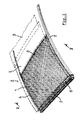
- Figure 1 shows, schematically and in a perspective view, a sunshade assembly applied to an open roof construction;
- Figure 2 shows a transverse cross-section according to II-II in figure 1;
- Figure 3 shows, schematically, a side elevational view of the sunshade assembly, and
- Figure 4 shows in a transversal cross-section an alternative embodiment of a guide.
- Firstly referring to figure 1, an open roof construction for a vehicle is illustrated schematically in dotted lines. Said open roof construction comprises a
roof opening 1 in a stationary roof part 2 and amovable closure panel 3 which, by means not illustrated in detail but known per se, can be moved for opening and closing saidroof opening 1. In figure 1 theclosure panel 3 has been illustrated in a position in which it opens theroof opening 1. - Below the roof opening 1 a sunshade assembly in accordance with the present invention is positioned. Basically, said sunshade assembly comprises a
flexible sunscreen 4, arotatable winding shaft 5 for winding and unwinding thesunscreen 4, and twoopposite guides 6 and 7 for cooperation with two opposite longitudinal edges of thesunscreen 4. - In so far the sunshade assembly has a conventional shape in which, preferably, the
winding shaft 5 is preloaded in a sense for winding thesunscreen 4 thereon. Further, in a way known per se, the end of thesunscreen 4 opposite the end which is wound onto the windingshaft 5 is provided with a pull beam 8 which may be gripped manually for operating thesunscreen 4 and locating it in a desired position. - Each
guide 6,7 extends longitudinally in a curved manner in a plane which substantially is perpendicular to thesunscreen 4 and in parallel to the respective longitudinal edge of thesunscreen 4. Said planes will be in parallel to an imaginary vertical plane extending through the longitudinal centre line of thesunscreen 4. In figure 2, which shows a cross-section according to II-II in figure 1, said planes have been illustrated schematically by chained lines P1 and P2. - Again referring to figure 2, it is shown clearly that
longitudinal edge sections 9 and 10 of thesunscreen 4 are housed in inner parts of theguides 6 and 7. Said longitudinal edge sections 9 (which extend at the respective edges of thesunscreen 4 along the entire length thereof) are less stretchable then the remainder of thesunscreen 4 which has a certain degree of stretchability and are tensioned in the longitudinal direction of the sunscreen. The manner, in which this tensioning occurs, will be elucidated later. - As illustrated in figure 1, but also in figure 3 which shows, schematically, a side elevational view of the sunshade assembly illustrated in figure 1, it is clearly visible that the
guides 6 and 7 are curved such that, considered in a longitudinal direction, a central portion thereof is elevated relative to the end portions thereof. - Again referring to figure 2, it is shown that each
guide 6, 7 at its concave side is provided with aninclined guide surface 11. Specifically, in the illustrated embodiment, theinclined guide surface 11 has, considered in a direction towards thesunscreen 4, aninner section 12 with a first inclination merging into acentral section 13 with a second higher inclination merging into anouter section 14 with again a lower inclination. The inclination may be defined by an angle α as explained later with respect to figure 4. - The curved shape of the
guides 6, 7 in combination with the fact that thelongitudinal edge sections 9 and 10 of thesunscreen 4 are less stretchable then the remainder of thesunscreen 4 results in a good retention of the sunscreen in the guides while keeping frictional forces low when moving thesunscreen 4 relative to the guides. - Figure 4 shows a cross-section of an alternative embodiment of a guide. In this embodiment, the inclined guide surface 11' has a straight configuration and includes an angle α with a vertical plane, which angle α preferably lies between 15° and 75°.
- Referring to figure 3, the sunshade assembly is illustrated schematically in a side elevational view. As stated, one can see clearly that the
guides 6, 7 have a curved shape with a central, elevated portion. For assuring that thesunscreen 4 with itsedge portions 9 and 10 is not pulled out of theguides 6, 7 near to the windingshaft 5, aguide bar 15 is provided above thesunscreen 4. - Further figure 3 illustrates a tensioning means 16 (for example a tensioning cable, tensioning rope, tensioning belt or alike) which with its one end at position 17 is attached to the free end of a respective edge portion of the
sunscreen 4 and which with its opposite end is connected to the windingshaft 5 or a mechanism cooperating therewith. The tensioning means 16, which extends around areversal roller 18, is meant to maintain (in combination with the winding shaft 5) the tensioning of the longitudinal edge sections of thesunscreen 4. The connection between the tensioning means 16 and windingshaft 5 is such, that the movement of the tensioning means is synchronized with the movement of the windingshaft 5. - From the figures it further appears clearly that, in the illustrated embodiment, the
longitudinal edge sections 9 and 10 substantially have the same thickness as the remainder of thesunscreen 4. - It has not been illustrated that parts of the
guides 6, 7 and/or parts of the sunscreen 4 (especially the parts thereof engaging theguides 6,7) are provided with a coating for reducing friction between thesunscreen 4 and theguides 6, 7. - The invention is not limited to the embodiments described before, which may be varied widely within the scope of the invention as defined by the appending claims.
Claims (15)
- Sunshade assembly, comprising a flexible sunscreen, a rotatable winding shaft for winding and unwinding the sunscreen and two opposite guides for cooperation with two opposite longitudinal edges of the sunscreen,
characterized in that
each guide extends longitudinally in a curved manner in a plane which substantially is perpendicular to the sunscreen and in parallel to the respective longitudinal edge of the sunscreen, and wherein longitudinal edge sections of the sunscreen are less stretchable than the remainder of the sunscreen and are tensioned in the longitudinal direction of the sunscreen. - Sunshade assembly according to claim 1, wherein the guides are curved such that, considered in a longitudinal direction, a central portion thereof is elevated relative to the end portions thereof.
- Sunshade assembly according to claim 1 or 2, wherein each guide at its concave side is provided with an inclined guide surface.
- Sunshade assembly according to claim 3, wherein the average angle of inclination of said inclined guide surface lies between 15° and 75°.
- Sunshade assembly according to claim 3 or 4, wherein, as seen in a transversal cross-section of the guide, the inclined guide surface has a curved shape.
- Sunshade assembly according to claim 5, wherein the inclined guide surface has, considered in a direction towards the sunscreen, an inner section with a first inclination merging into a central section with a second higher inclination merging into an outer section with again a lower inclination.
- Sunshade assembly according to one of the previous claims, wherein the longitudinal edge sections of the sunscreen are made of a different material than the remainder of the sunscreen.
- Sunshade assembly according to one of the claims 1-6, wherein the longitudinal edge sections of the sunscreen are made of the same material as the remainder of the sunscreen, however impregnated or treated with a substance to make these sections less stretchable.
- Sunshade assembly according to one of the previous claims, wherein said longitudinal edge sections are substantially non-stretchable.
- Sunshade assembly according to one of the previous claims, wherein the longitudinal edge sections of the sunscreen substantially have the same thickness as the remainder of the sunscreen.
- Sunshade assembly according to one of the previous claims, wherein the tensioning of the longitudinal edge sections in the longitudinal direction is caused, at one end thereof, by a winding force of the winding shaft and, at the opposite end thereof, by tensioning means engaging said edge sections.
- Sunshade assembly according to claim 11, wherein said tensioning means comprise tensioning cables, ropes, belts or alike.
- Sunshade assembly according to claim 12 or 13, wherein the tensioning means are moved in synchronism with the winding/unwinding movement of the winding shaft.
- Sunshade assembly according to one of the previous claims, wherein at least one of the engaging parts of the sunscreen and guide is provided with a coating for reducing friction therebetween.
- Open roof construction for a vehicle, comprising a roof opening in a stationary roof part and a movable closure panel for opening and closing said roof opening, wherein below said roof opening there is provided a sunshade assembly according to any of the previous claims.
Priority Applications (4)
| Application Number | Priority Date | Filing Date | Title |
|---|---|---|---|
| EP06121870.7A EP1908616B1 (en) | 2006-10-06 | 2006-10-06 | Sunshade assembly and open roof construction provided therewith |
| JP2007262514A JP5584389B2 (en) | 2006-10-06 | 2007-10-05 | Sunshade assembly and open roof structure provided with the sunshade assembly |
| US11/867,944 US7744151B2 (en) | 2006-10-06 | 2007-10-05 | Sunshade assembly and open roof construction provided therewith |
| CN2007103051467A CN101195334B (en) | 2006-10-06 | 2007-10-08 | Sunshade assembly and open roof construction provided therewith |
Applications Claiming Priority (1)
| Application Number | Priority Date | Filing Date | Title |
|---|---|---|---|
| EP06121870.7A EP1908616B1 (en) | 2006-10-06 | 2006-10-06 | Sunshade assembly and open roof construction provided therewith |
Publications (2)
| Publication Number | Publication Date |
|---|---|
| EP1908616A1 true EP1908616A1 (en) | 2008-04-09 |
| EP1908616B1 EP1908616B1 (en) | 2013-04-17 |
Family
ID=37989850
Family Applications (1)
| Application Number | Title | Priority Date | Filing Date |
|---|---|---|---|
| EP06121870.7A Active EP1908616B1 (en) | 2006-10-06 | 2006-10-06 | Sunshade assembly and open roof construction provided therewith |
Country Status (4)
| Country | Link |
|---|---|
| US (1) | US7744151B2 (en) |
| EP (1) | EP1908616B1 (en) |
| JP (1) | JP5584389B2 (en) |
| CN (1) | CN101195334B (en) |
Cited By (5)
| Publication number | Priority date | Publication date | Assignee | Title |
|---|---|---|---|---|
| WO2010022768A1 (en) * | 2008-08-27 | 2010-03-04 | Inalfa Roof Systems Group B.V. | Sunshade assembly and open roof construction provided therewith |
| CN102510814A (en) * | 2009-09-28 | 2012-06-20 | 爱信精机株式会社 | Roll shade device |
| CN102555743A (en) * | 2010-11-05 | 2012-07-11 | 爱信精机株式会社 | Sunshade apparatus for vehicle |
| FR2989637A1 (en) * | 2012-04-23 | 2013-10-25 | Webasto Systemes Carrosserie | Screening device for obscuring opening e.g. mobile panel, in car, has fabric extending above set of wings, and cord extending above fabric on level from wing, where cord is stretched in elastic manner to press fabric against wing |
| US10173503B2 (en) | 2015-07-08 | 2019-01-08 | Inalfa Roof Systems Group B.V. | Open roof construction for a vehicle and rollo assembly for use therein |
Families Citing this family (9)
| Publication number | Priority date | Publication date | Assignee | Title |
|---|---|---|---|---|
| DE102007041298B4 (en) * | 2007-08-31 | 2010-06-10 | Webasto Ag | Roller blind arrangement for a motor vehicle |
| US7798568B2 (en) * | 2008-08-06 | 2010-09-21 | Inalfa Roof Systems Group B.V. | Sunshade assembly and open roof construction provided therewith |
| JP2011230705A (en) * | 2010-04-28 | 2011-11-17 | Toyota Motor Corp | Shade apparatus for vehicle |
| EP2508375B1 (en) * | 2011-04-07 | 2015-12-16 | Inalfa Roof Systems Group B.V. | Rollo assembly and open roof construction provided therewith |
| AT513942B1 (en) * | 2013-01-22 | 2017-11-15 | Htp High Tech Plastics Gmbh | Device for covering a viewing opening |
| EP2987667B1 (en) | 2014-08-18 | 2019-10-09 | Inalfa Roof Systems Group B.V. | Guide and sunshade assembly provided therewith |
| EP2987668B1 (en) * | 2014-08-18 | 2019-04-24 | Inalfa Roof Systems Group B.V. | Sunshade assembly |
| BR112018014365B1 (en) * | 2016-01-13 | 2024-01-02 | Cornellcookson, Llc | ROLL-UP DOORS, ROLL-UP DOOR ASSEMBLY AND METHOD FOR ATTACHING THEM TO A GUIDE |
| CN112440697B (en) | 2019-08-27 | 2023-11-24 | 英纳法天窗系统集团有限公司 | Sunshade system and method for manufacturing components thereof |
Citations (3)
| Publication number | Priority date | Publication date | Assignee | Title |
|---|---|---|---|---|
| FR2750930A1 (en) * | 1996-07-10 | 1998-01-16 | Soc D Toits Ouvrants Automobil | Cloth or canvas roof cover for automobiles |
| DE19929047A1 (en) * | 1999-06-25 | 1999-11-18 | Audi Ag | Car with rolling roof and roof bearing module |
| DE10230444A1 (en) * | 2002-07-06 | 2004-01-22 | Daimlerchrysler Ag | Sliding sun roof for car is made up of connected slats and is operated by drive comprising motor mounted inside drum on which it is wound |
Family Cites Families (16)
| Publication number | Priority date | Publication date | Assignee | Title |
|---|---|---|---|---|
| JPS57157700U (en) * | 1981-03-30 | 1982-10-04 | ||
| JPH0750558Y2 (en) * | 1988-03-25 | 1995-11-15 | トーソー株式会社 | Roll blinds with side rails |
| US5579820A (en) * | 1994-11-10 | 1996-12-03 | Lepage; Robert | Roll-up door for vehicle shelters |
| JP2826308B1 (en) * | 1997-09-04 | 1998-11-18 | モリト株式会社 | Roll screen device |
| DE19739919C2 (en) * | 1997-09-11 | 1999-07-08 | Rockwell International Gmbh | Sun blind for a motor vehicle roof |
| JP2000190733A (en) * | 1997-09-11 | 2000-07-11 | Meritor Automotive Gmbh | Blind for roof for vehicle |
| DE10022452A1 (en) * | 2000-05-09 | 2001-11-15 | Bautex Adolf Stoever Soehne Gm | Blind for a roller blind with side guide |
| DE10046553A1 (en) * | 2000-09-19 | 2002-04-04 | Bos Gmbh | Window roller blind for curved or non-rectangular vehicle windows |
| DE10122570C1 (en) * | 2001-05-09 | 2002-07-25 | Webasto Vehicle Sys Int Gmbh | Sun blind, for vehicle roof, has grip elements on guide rails able to be coupled to side edges of moving blind strip |
| CA2446648C (en) * | 2003-07-10 | 2005-03-29 | Tnr Industrial Doors Inc. | Roll-up flexible door and guides therefor |
| DE10331514A1 (en) * | 2003-07-11 | 2005-02-03 | Arvinmeritor Gmbh | Sunshade assembly for a vehicle roof |
| US7063227B2 (en) * | 2003-09-05 | 2006-06-20 | Satco, Inc. | Air cargo container |
| DE102004017459A1 (en) * | 2004-04-08 | 2005-10-27 | Arvinmeritor Gmbh | Roller blind for a sunroof system |
| CN2700152Y (en) * | 2004-04-27 | 2005-05-18 | 皇田工业股份有限公司 | Sunshade curtain with guide rail |
| JP2006051925A (en) * | 2004-05-17 | 2006-02-23 | Asmo Co Ltd | Sunshade unit |
| DE102005024657C5 (en) * | 2004-11-19 | 2016-04-21 | Webasto Ag | Roller blind arrangement for a vehicle |
-
2006
- 2006-10-06 EP EP06121870.7A patent/EP1908616B1/en active Active
-
2007
- 2007-10-05 US US11/867,944 patent/US7744151B2/en active Active
- 2007-10-05 JP JP2007262514A patent/JP5584389B2/en not_active Expired - Fee Related
- 2007-10-08 CN CN2007103051467A patent/CN101195334B/en active Active
Patent Citations (3)
| Publication number | Priority date | Publication date | Assignee | Title |
|---|---|---|---|---|
| FR2750930A1 (en) * | 1996-07-10 | 1998-01-16 | Soc D Toits Ouvrants Automobil | Cloth or canvas roof cover for automobiles |
| DE19929047A1 (en) * | 1999-06-25 | 1999-11-18 | Audi Ag | Car with rolling roof and roof bearing module |
| DE10230444A1 (en) * | 2002-07-06 | 2004-01-22 | Daimlerchrysler Ag | Sliding sun roof for car is made up of connected slats and is operated by drive comprising motor mounted inside drum on which it is wound |
Cited By (7)
| Publication number | Priority date | Publication date | Assignee | Title |
|---|---|---|---|---|
| WO2010022768A1 (en) * | 2008-08-27 | 2010-03-04 | Inalfa Roof Systems Group B.V. | Sunshade assembly and open roof construction provided therewith |
| CN102510814A (en) * | 2009-09-28 | 2012-06-20 | 爱信精机株式会社 | Roll shade device |
| EP2484545A4 (en) * | 2009-09-28 | 2012-10-10 | Aisin Seiki | Roll shade device |
| CN102555743A (en) * | 2010-11-05 | 2012-07-11 | 爱信精机株式会社 | Sunshade apparatus for vehicle |
| CN102555743B (en) * | 2010-11-05 | 2015-04-15 | 爱信精机株式会社 | Sunshade apparatus for vehicle |
| FR2989637A1 (en) * | 2012-04-23 | 2013-10-25 | Webasto Systemes Carrosserie | Screening device for obscuring opening e.g. mobile panel, in car, has fabric extending above set of wings, and cord extending above fabric on level from wing, where cord is stretched in elastic manner to press fabric against wing |
| US10173503B2 (en) | 2015-07-08 | 2019-01-08 | Inalfa Roof Systems Group B.V. | Open roof construction for a vehicle and rollo assembly for use therein |
Also Published As
| Publication number | Publication date |
|---|---|
| EP1908616B1 (en) | 2013-04-17 |
| JP2008094389A (en) | 2008-04-24 |
| JP5584389B2 (en) | 2014-09-03 |
| US20080252105A1 (en) | 2008-10-16 |
| CN101195334A (en) | 2008-06-11 |
| US7744151B2 (en) | 2010-06-29 |
| CN101195334B (en) | 2012-06-20 |
Similar Documents
| Publication | Publication Date | Title |
|---|---|---|
| US7744151B2 (en) | Sunshade assembly and open roof construction provided therewith | |
| EP2338716B1 (en) | Sunshade assembly and open roof construction provided therewith | |
| US9090147B2 (en) | Sunshade assembly and open roof construction provided therewith | |
| EP2484545A1 (en) | Roll shade device | |
| WO2010022768A1 (en) | Sunshade assembly and open roof construction provided therewith | |
| US9387748B2 (en) | Roll shade apparatus for vehicle | |
| KR20090033415A (en) | Closure with screen with flexible sides | |
| WO2010022769A1 (en) | Sunshade assembly and open roof construction provided therewith | |
| US8508068B2 (en) | Power supply apparatus for sliding door | |
| EP2987668B1 (en) | Sunshade assembly | |
| EP2393683B1 (en) | Sunshade assembly | |
| KR20250123728A (en) | The wedge-shaped extensible-clamp | |
| KR20130037642A (en) | Roof assembly for a vehicle | |
| EP2093086A1 (en) | Sunshade assembly and open roof construction provided therewith | |
| EP3936733B1 (en) | Equipment holder device | |
| US12054986B2 (en) | Shade guide structure | |
| US10960740B2 (en) | Open roof construction for a vehicle and rollo assembly for use therein | |
| CN113119698B (en) | Roller shutter mechanism for vehicle sunroof and guiding device thereof | |
| EP1841680B1 (en) | Method and device for mounting a rope on a rope pulley | |
| EP1780163A1 (en) | Door system | |
| CN120211610B (en) | Rolling belt connecting device for blinds and blinds | |
| AU714050B2 (en) | A device and a method for guiding a belt | |
| CN120552585A (en) | Roller blind assembly with two roller blind sections | |
| GB2113637A (en) | A device for clamping to a sheet of flexible material | |
| EP1916217A1 (en) | Slat door wound around an axis |
Legal Events
| Date | Code | Title | Description |
|---|---|---|---|
| PUAI | Public reference made under article 153(3) epc to a published international application that has entered the european phase |
Free format text: ORIGINAL CODE: 0009012 |
|
| AK | Designated contracting states |
Kind code of ref document: A1 Designated state(s): AT BE BG CH CY CZ DE DK EE ES FI FR GB GR HU IE IS IT LI LT LU LV MC NL PL PT RO SE SI SK TR |
|
| AX | Request for extension of the european patent |
Extension state: AL BA HR MK RS |
|
| 17P | Request for examination filed |
Effective date: 20081003 |
|
| 17Q | First examination report despatched |
Effective date: 20081030 |
|
| AKX | Designation fees paid |
Designated state(s): DE FR GB |
|
| GRAP | Despatch of communication of intention to grant a patent |
Free format text: ORIGINAL CODE: EPIDOSNIGR1 |
|
| GRAS | Grant fee paid |
Free format text: ORIGINAL CODE: EPIDOSNIGR3 |
|
| GRAA | (expected) grant |
Free format text: ORIGINAL CODE: 0009210 |
|
| AK | Designated contracting states |
Kind code of ref document: B1 Designated state(s): DE FR GB |
|
| REG | Reference to a national code |
Ref country code: GB Ref legal event code: FG4D |
|
| REG | Reference to a national code |
Ref country code: DE Ref legal event code: R096 Ref document number: 602006035691 Country of ref document: DE Effective date: 20130613 |
|
| PGFP | Annual fee paid to national office [announced via postgrant information from national office to epo] |
Ref country code: GB Payment date: 20131028 Year of fee payment: 8 |
|
| PLBE | No opposition filed within time limit |
Free format text: ORIGINAL CODE: 0009261 |
|
| STAA | Information on the status of an ep patent application or granted ep patent |
Free format text: STATUS: NO OPPOSITION FILED WITHIN TIME LIMIT |
|
| 26N | No opposition filed |
Effective date: 20140120 |
|
| REG | Reference to a national code |
Ref country code: DE Ref legal event code: R097 Ref document number: 602006035691 Country of ref document: DE Effective date: 20140120 |
|
| GBPC | Gb: european patent ceased through non-payment of renewal fee |
Effective date: 20141006 |
|
| PG25 | Lapsed in a contracting state [announced via postgrant information from national office to epo] |
Ref country code: GB Free format text: LAPSE BECAUSE OF NON-PAYMENT OF DUE FEES Effective date: 20141006 |
|
| REG | Reference to a national code |
Ref country code: FR Ref legal event code: PLFP Year of fee payment: 10 |
|
| REG | Reference to a national code |
Ref country code: FR Ref legal event code: PLFP Year of fee payment: 11 |
|
| REG | Reference to a national code |
Ref country code: FR Ref legal event code: PLFP Year of fee payment: 12 |
|
| REG | Reference to a national code |
Ref country code: FR Ref legal event code: PLFP Year of fee payment: 13 |
|
| PGFP | Annual fee paid to national office [announced via postgrant information from national office to epo] |
Ref country code: DE Payment date: 20251029 Year of fee payment: 20 |
|
| PGFP | Annual fee paid to national office [announced via postgrant information from national office to epo] |
Ref country code: FR Payment date: 20251027 Year of fee payment: 20 |