EP1908602A1 - Binder - Google Patents
Binder Download PDFInfo
- Publication number
- EP1908602A1 EP1908602A1 EP06781684A EP06781684A EP1908602A1 EP 1908602 A1 EP1908602 A1 EP 1908602A1 EP 06781684 A EP06781684 A EP 06781684A EP 06781684 A EP06781684 A EP 06781684A EP 1908602 A1 EP1908602 A1 EP 1908602A1
- Authority
- EP
- European Patent Office
- Prior art keywords
- binder
- ring
- back part
- ring parts
- portions
- Prior art date
- Legal status (The legal status is an assumption and is not a legal conclusion. Google has not performed a legal analysis and makes no representation as to the accuracy of the status listed.)
- Granted
Links
- 239000011230 binding agent Substances 0.000 title claims abstract description 197
- 238000012545 processing Methods 0.000 claims abstract description 34
- 230000002093 peripheral effect Effects 0.000 claims abstract description 23
- 230000007246 mechanism Effects 0.000 description 9
- 230000035515 penetration Effects 0.000 description 7
- 230000004075 alteration Effects 0.000 description 2
- 210000001503 joint Anatomy 0.000 description 2
- 230000001105 regulatory effect Effects 0.000 description 2
- 230000008901 benefit Effects 0.000 description 1
- 239000002131 composite material Substances 0.000 description 1
- 230000008878 coupling Effects 0.000 description 1
- 238000010168 coupling process Methods 0.000 description 1
- 238000005859 coupling reaction Methods 0.000 description 1
- 238000001514 detection method Methods 0.000 description 1
- 230000000694 effects Effects 0.000 description 1
- 230000007613 environmental effect Effects 0.000 description 1
- 238000002347 injection Methods 0.000 description 1
- 239000007924 injection Substances 0.000 description 1
- 230000004048 modification Effects 0.000 description 1
- 238000012986 modification Methods 0.000 description 1
- 238000000465 moulding Methods 0.000 description 1
- 230000000630 rising effect Effects 0.000 description 1
- 230000007480 spreading Effects 0.000 description 1
Images


Classifications
-
- B—PERFORMING OPERATIONS; TRANSPORTING
- B42—BOOKBINDING; ALBUMS; FILES; SPECIAL PRINTED MATTER
- B42F—SHEETS TEMPORARILY ATTACHED TOGETHER; FILING APPLIANCES; FILE CARDS; INDEXING
- B42F13/00—Filing appliances with means for engaging perforations or slots
- B42F13/16—Filing appliances with means for engaging perforations or slots with claws or rings
- B42F13/20—Filing appliances with means for engaging perforations or slots with claws or rings pivotable about an axis or axes parallel to binding edges
- B42F13/22—Filing appliances with means for engaging perforations or slots with claws or rings pivotable about an axis or axes parallel to binding edges in two sections engaging each other when closed
-
- B—PERFORMING OPERATIONS; TRANSPORTING
- B42—BOOKBINDING; ALBUMS; FILES; SPECIAL PRINTED MATTER
- B42B—PERMANENTLY ATTACHING TOGETHER SHEETS, QUIRES OR SIGNATURES OR PERMANENTLY ATTACHING OBJECTS THERETO
- B42B5/00—Permanently attaching together sheets, quires or signatures otherwise than by stitching
- B42B5/08—Permanently attaching together sheets, quires or signatures otherwise than by stitching by finger, claw or ring-like elements passing through the sheets, quires or signatures
Definitions
- the present invention relates to a binder for binding brochures such as documents.
- JP 2000-289376 A discloses a plastic-made binder which is used to bind loose-leaf papers on the market or documents punched by a multi-hole puncher.
- This binder is a one-piece molded product in which a large number of 1/2 ring portions are arranged at given intervals in two lines on both sides of a back part of the binder, and the back part of the binder itself is a hinge composed of two divided sections.
- one line of 1/2 ring portions respectively include spherical-shaped projections on the leading ends thereof, whereas the other line of 1/2 ring portions respectively include in the leading ends thereof holes respectively having shapes corresponding to their associated projections.
- means for handling a binder is an important element.
- the binder it is necessary for the binder to have a structure suitable for mechanically handling or carrying out binder operations such as binder feeding, holding and fitting operations.
- the binder disclosed in JP 2000-289376 A is structured on the assumption that it is mounted by hand into a binding processing machine but not on the assumption that it is handled mechanically. Thus, it is difficult to use this binder in a binding processing machine which does not require the manual operation.
- a binder having a structure which is suitable for use in the binding processing machine has been proposed.
- a binder disclosed in JP 2004-237578 A is structured such that, the back part of the binder is projected forwardly or toward the back surface of the binder and thus, when a number of binders are piled up on top of each other, the back part of one binder can be contacted with the front surface or back surface of the other binder.
- the individual binders can be piled up in such a manner they respectively can keep their initial shapes, whereby, when the binders are loaded into a cartridge provided in the binding processing machine, the smoothness of the feeding and mounting of the binders can be improved.
- a binder disclosed in JP 2004-237579 A is structured such that one or more recessed portions are formed on one of the front and back surfaces of the back part of the binder, and such that one or more projecting portions to be fitted and paired with the recessed portions are formed on the other surface, whereby a plurality of binders can be connected together while they are piled up on top of each other. This structure can facilitate the handling of the piled-up binders.
- a plastic-made binder disclosed in JP 2004-237580 A has a scarf joint structure in which, in the end portions of sectioned ring portions to be fitted and paired with each other, there are provided symmetrical steps extending in the radial direction thereof. Further, this binder includes a hook portion on one end thereof, and a catch portion to be fitted and paired with the hook portion on the other end thereof, thereby providing means for fitting its sectioned ring portions with each other. Therefore, this binder requires less power for fitting when compared with the structure of the binder disclosed in JP 2000-289376 A in which the spherical projections are fitted into the holes. Also, according to this binder, the structure of a die for molding it can be further simplified.
- the binding processing machine To enable the binding processing machine to carry out a binding processing operation, there are necessary means for holding a binder and a pusher or a press mechanism for folding and fitting the ring parts of the binder with each other.
- the means for holding the binder is almost unable to mount the binder while it holds the ring parts which are folded by the pusher or the like; and, therefore, the binder holding means actually holds the back part of the binder.
- One or one or more embodiments of the present invention provide a binder that can be held stably, according to which a mounting failure of the binder due to an inclined orientation of the binder can be resolved.
- a binder includes a back part, and a plurality of ring parts arranged at certain intervals along a longitudinal direction of the back part on respective sides of the back part, each of the ring parts being openable and closable.
- At least one of the ring parts includes a plane portion formed on an outer peripheral surface at a portion intersecting with the back part. The plane portion is adapted to be received by a plane table provided on a binder holding member of a binding processing machine so as to keep the binder in a regular orientation.
- each of the ring parts may include a center 1/3 ring part coupled to the back part; and 1/3 ring parts hinge-connected to respective ends of the center 1/3 ring part, and the center 1/3 ring parts of at least one of the ring parts may include the plane portion at the portion intersecting with the back part.
- the plane portion may be formed such that a central portion of the outer peripheral surface of the ring part in a right-and-left direction is cut out in a form of a groove along a circumferential direction of the ring part.
- a binder includes a back part, and a plurality of ring parts arranged at certain intervals along a longitudinal direction of the back part on respective sides of the back part, each of the ring parts being openable and closable.
- the back part includes a step portion on an inner peripheral side thereof, wherein the step portion is engagable with the binder holding member of the binding processing machine so as to keep the binder in the regular orientation.
- the back part may have a T-shaped section.
- a binder is configured such that a plane portion is formed on an outer peripheral surface of at least one ring part at a portion intersecting with a back part of the binder, and such that, when a binder holding member of a binding processing machine holds the binder, the plane portion of the binder contacts with a plane table provided on the binder holding member. Therefore, the binder is held in such a state that the binder cannot incline or rotate.
- a binding processing operation can be carried out in the binding processing machine while the binder is held in a regular orientation. Accordingly, a mounting failure due to an inclined orientation of the binder and be resolved.
- the back part includes a step portion and the step portion can be held by the binder holding member of the binding processing machine, the inclination of the orientation of the binder can be prevented.
- the ring parts including the plane portions and the back part including the step portion can further prevent the inclined orientation of the binder.
- Figs. 1 to 4(b) respectively show a binder 11b.
- the binder 11b is a plastic injection molded product which includes a back part 12 having a T-shaped section and ring parts 13, 14 and 15 connected to each other at given intervals by the back part 12.
- the ring part is sectioned into three parts, namely, a center 1/3 ring part 13 connected to the back part 12, and two 1/3 ring parts 14 and 15 respectively connected to the two ends of the center 1/3 part 13 through their respective small-thickness hinge portions.
- grooves 16 are formed on the inner peripheral surfaces of the 1/3 ring parts 14 and 15 so as to extend in the circumferential direction of the ring part.
- a hook portion 17 is formed on the leading end of one 1/3 ring part 14, and a catch portion 18, with which the hook portion 17 can be fitted, is formed on the leading end of the other 1/3 ring part 15.
- the paired 1/3 ring parts 14 and 15 are rotated about the hinge portions, and their respective hook portion 17 and catch portion 18 are fitted with each other, thereby forming a complete ring.
- pins 19 in the central portion of the inner peripheral surface of the center 1/3 part that is situated in the center of the binder 11b in the longitudinal direction thereof as well as in the central portions of the inner peripheral surfaces of the center 1/3 ring parts that are respectively situated fourth from the two ends of the binder 11b, there are provided pins 19. Also, as shown in Figs. 2 and 4(a) , in the central portions of the outer peripheral surfaces of these three center 1/3 ring parts 13, there are formed pin holes 20 which respectively correspond to the pins 19. When a plurality of binders 11b are piled up on top of each other and the pins 19 and pin holes 20 thereof are fitted with each other, the plurality binders 11b are connected together in a piled-up manner.
- Figs. 5(a) and 5(b) respectively show a state just before the 1/3 ring parts 14 and 15 of binders are folded and fitted with each other.
- Fig. 5(b) shows the binder 11b that is shown in Figs. 1 to 4(b)
- Fig. 5(a) shows a binder 11b which is smaller in diameter than the binder 11b.
- the two binders 11b and 11b are equal to each other in the ring pitch and in the widths of the ring parts 13, 14 and 15 but are different from each other in the outside diameter and in the inside diameter, whereby, according to the number of sheets of paper to be bound, it is systematized such that a binder having a proper diameter can be selected and loaded into a binding processing machine for actual use.
- Figs. 6(a1) to 6(b2) respectively show a state where the 1/3 ring parts 14 and 15 are fitted with each other (in these figures, the back part 12 is not shown). Specifically, Figs. 6(a1) and 6(b1) respectively show states where their fitted portions face upward, whereas Figs. 6(a2) and 6(b2) respectively shown states where their fitted portions face downward.
- Figs. 7(a1) and 7(b1) respectively show sections in a state just before fitting
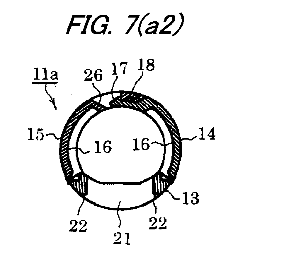
- Figs. 7(a2) and 7(b2) respectively show sections in a state of fitting.
- the two kinds of binders 11a and 11b having different ring diameters are equal to each other in the diameter direction thickness t of the central portions of the center 1/3 ring parts 13 thereof.
- a plane portion 22 is formed in the center 1/3 ring part 13.
- the plane portion 22 is formed to have such a shape that the central portion of the outer peripheral surface of the center 1/3 ring part 13 is cut out in a direction perpendicular to the normal of the peripheral surface with a width equal to the penetration hole 21.
- These two kinds of binders 11a and 11b are also the same in the distance d between their plane portions 22 and the tangent lines of the outer peripheral surfaces parallel to the plane portions 22.
- the two kinds of binders 11a and 11b are the same in the thickness t of the center 1/3 ring parts 13 thereof and thus a plurality of binders can be piled up on top of each other closely with no clearance between them.
- a plurality of binders can be piled up on top of each other closely with no clearance between them.
- Figs. 8(a2) and 8(b2) when the binders 11a and 11b are piled up in the same number (in the present embodiment, the number of the binders 11a is eight and the number of the binders 11b is eight), their respective total thicknesses are the same.
- control on the amount of feeding of the binder within a cartridge control on the detection of the remaining amount of the binder from the amount of movement of a pusher for pushing the binder for feeding, and other control can be standardized, thereby being able to simplify the processings to be carried out by the control part of the binding processing machine.
- Fig. 9 is an enlarged view of the A portion shown in Figs. 1 and 2 .
- Fig. 9 on the two side surfaces of each of the three A portions respectively shown in Fig. 1 of the center 1/3 ring part 13, there are provided spherical-shaped projecting portions 23 which respectively function as position regulating portions.
- binders which have been loaded into the cartridge of the binding processing machine in a piled-up manner, are regulated in the lateral movement thereof by feed guides G provided within the cartridge, whereby, in Fig. 9 , they are fed in the far direction of the sheet of Fig. 9 .
- the projecting portions 23 provided on the one or two side surfaces of one or more ring parts hold the side surface of the center 1/3 ring part in a state where it is in point contact with the wall surface of the feed guide, whereby the whole of the ring part is not surface contacted with the feed guide and thus the binder can be fed smoothly with low friction resistance.
- Figs. 10(a) to 10(c) respectively show a fitting mechanism which is provided on the leading end of the ring part.
- step portions 24 are formed on the inner peripheral surfaces of the right and left portions of the 1/3 ring part 14 between which an upward rising hook portion 17 is provided.
- Step portions 25 are formed on the outer peripheral surfaces of the right and left portions of the 1/3 ring part 15 between which a catch portion 18 is provided.
- the step portions 25 respectively correspond to the step portions 24 of the other 1/3 ring part 14.
- the present fitting mechanism is configured as a scarf joint structure.
- the hook portion 17 of the 1/3 ring part 14 is provided at a position which is retracted from its right and left step portions 24. Slits are provided between the hook portion 17 and the respective stepped portions 24, whereby the hook portion 17 is allowed to flex freely.
- the hook portion 17 can be engaged with the vertical wall of the rear end of the catch portion 18.
- the vertical wall of the catch portion 18 exists at a position retreated farther from the right and left step portions 25, whereas the leading end of the catch portion 18 projects forwardly beyond the step portions 25.
- a hole 26 is formed through the rear of the catch portion 18 of the 1/3 ring part 15.
- the hole 26 penetrates through the 1/3 ring part 15 in the radial direction thereof. Therefore, as shown in Figs. 7(a2) and 7(b2) , in the engaged state, the leading end of the hook portion 17 is exposed inside of the hole 26 and can be observed from outside. Thus, the hook portion 17 can be pressed down from above with a pin or the like to remove the engagement between the hook portion 17 and catch portion 18, thereby releasing the pair of 1/3 ring parts 14 and 15.
- Fig. 11(b) shows another embodiment of a binder according to the invention, in which a pair of 1/3 ring parts 42, 43 of a binder 41 is symmetrical in shape.
- the half portions of the leading ends of the two ring parts 42, 43 are respectively formed as upward facing hook portions 44, whereas the other half portions are respectively formed as downward facing hook portions 45.
- the paired 1/3 ring parts 42, 43 are closed, the mutually opposed upward facing hook portions 44 and downward facing hook portions 45 are engaged with each other, thereby coupling the pair of 1/3 ring parts 42, 43 together.
- the upward facing hook portion 44 and downward facing hook portion 45 may not be always formed in the leading ends of all of the 1/3 ring parts 42, 43, but the hook portions 44 and 45 may also be formed only in the leading ends of the ring parts provided on the longitudinal-direction two ends of the binder as well as the important ring parts provided between the two ends of the binder.
- Figs. 12 and 13 respectively show a state where a binder pickup unit 51 of a binding processing machine holds a binder 11b. While a binding processing machine may be structured in various manners, the binder pickup unit 51 is an example of means for taking out one binder from a cartridge in which a large number of binders are loaded in a piled-up manner, and supplying the binder into a binding processing mechanism part into which papers is to be mounted.
- the binder pickup unit 51 includes a table block 52 shown in Fig. 14 and two hook lever blocks 53 respectively disposed on the front and rear surfaces of the table block 52, while the table block 52 and hook lever blocks 53 are respectively assembled to a frame (not shown).
- On the upper surface of the table block 52 there are provided plane tables 54 at the same pitch as the ring pitch of the binders 11a and 11b respectively shown in Figs. 7(a1) to 7(b2) , while the upper surfaces of the plane tables 54 respectively receive the plane portions 22 of the center 1/3 ring parts 13 of the binders 11a and 11b.
- Each of the paired front and rear hook lever blocks 53 includes a plurality of hook levers 55 which are arranged in a comb teeth shape at the same pitch as the ring pitch.
- the mutually opposed hook levers 55 are interposed zigzag between the plane tables 54, can be opened and closed symmetrically by a lever opening/closing mechanism (not shown) and, when they are closed, can hold the step portion of the T-section back part 12 of the binder 11a or 11b.
- Figs. 15 (1) to 15(b2) respectively show the details of the binder pickup unit 51.
- Fig. 15 (1) shows a state thereof in which the binder pickup unit 51 grabs or holds the binder 11a or 11b
- Fig. 15(a0) shows the binder 11a
- Figs. 15(a1) and 15(a2) are section views of the binder pickup unit 51, respectively showing the states thereof where the binder pickup unit 51 grabs the binder 11a.
- Fig. 15(b0) shows the binder 11b
- Figs. 15(b1) and 15(b2) are section views of the binder pickup unit 51, respectively showing the states thereof in which the binder pickup unit 51 grabs the binder 11b.
- the paired front and rear hook levers 55 can be respectively engaged with the step portions of the back part 12 having a T-shaped section to thereby press the back part 12 against the table block 52. Further, the plane portions 22 can also be pressed against the plane tables 54 of the table block 52.
- the binders 11a and 11b Since there are formed the plane portions 22 in the binders 11a and 11b and the plane portions 22 can be received by the plane tables 54 of the table block 52, the binders 11a and 11b can be prevented from inclining in orientation, whereby they can be held stably in their regular orientations. Also, because the right and left sides of the plane portions 22 of the binders 11a and 11b are surrounded by the side walls of the center 1/3 ring parts 13, when the plane tables 54 of the table block 52 are fitted with the plane portions 22, the longitudinal-direction positioning of the binders 11a and 11b can be attained.
- the penetration holes 21 are formed in the respective center 1/3 ring parts 13 to allow the flexing of the ring parts 13 in the width direction thereof, even when the whole lengths of the binders 11a and 11b are extended due to variations in heat, the plane portions 22 of the center 1/3 ring parts 13 are fitted with the plane tables 54 of the table block 52 to thereby correct the deviation of the ring pitch forcibly. Accordingly, the binding processing can be carried out at a regular ring pitch.
- the present invention can prevent the binder from losing regular orientation and thereby can eliminate the poor binding of the binder.
Landscapes
- Engineering & Computer Science (AREA)
- Textile Engineering (AREA)
- Sheet Holders (AREA)
Abstract


Description
- The present invention relates to a binder for binding brochures such as documents.
-
JP 2000-289376 A - In the field of office automation equipment, there is known a kind of composite machine which includes a copying machine and a stapler incorporated in the copying machine and is capable of carrying out operations ranging from a copying operation to a binding operation. It may be more convenient to be able to provide an automatic binding processing machine which punches holes in copied papers and attaches a binder to the copied papers. It can be estimated that potential demand for such automatic binding processing machine must be large.
- To realize this type of binding processing machine, means for handling a binder is an important element. For example, it is necessary for the binder to have a structure suitable for mechanically handling or carrying out binder operations such as binder feeding, holding and fitting operations. However, the binder disclosed in
JP 2000-289376 A - In view of this, there has been proposed a binder having a structure which is suitable for use in the binding processing machine. For example, a binder disclosed in
JP 2004-237578 A - Also, a binder disclosed in
JP 2004-237579 A - Further, a plastic-made binder disclosed in
JP 2004-237580 A JP 2000-289376 A - To enable the binding processing machine to carry out a binding processing operation, there are necessary means for holding a binder and a pusher or a press mechanism for folding and fitting the ring parts of the binder with each other. The means for holding the binder is almost unable to mount the binder while it holds the ring parts which are folded by the pusher or the like; and, therefore, the binder holding means actually holds the back part of the binder.
- However, it is not easy to hold the narrow back part and maintain the binder in a proper orientation until the binding processing is completed. When the binder is rotated about the back part thereof and is thereby inclined from its regular orientation, the ring parts might not be inserted into punched holes formed in papers or the ring parts might not be fitted with each other properly.
- One or one or more embodiments of the present invention provide a binder that can be held stably, according to which a mounting failure of the binder due to an inclined orientation of the binder can be resolved.
- According to one or one or more embodiments of the invention, a binder includes a back part, and a plurality of ring parts arranged at certain intervals along a longitudinal direction of the back part on respective sides of the back part, each of the ring parts being openable and closable. At least one of the ring parts includes a plane portion formed on an outer peripheral surface at a portion intersecting with the back part. The plane portion is adapted to be received by a plane table provided on a binder holding member of a binding processing machine so as to keep the binder in a regular orientation.
- According to one or one or more embodiments of the invention, each of the ring parts may include a center 1/3 ring part coupled to the back part; and 1/3 ring parts hinge-connected to respective ends of the center 1/3 ring part, and the center 1/3 ring parts of at least one of the ring parts may include the plane portion at the portion intersecting with the back part.
- According to one or one or more embodiments of the invention, the plane portion may be formed such that a central portion of the outer peripheral surface of the ring part in a right-and-left direction is cut out in a form of a groove along a circumferential direction of the ring part.
- According to one or one or more embodiments of the invention, a binder includes a back part, and a plurality of ring parts arranged at certain intervals along a longitudinal direction of the back part on respective sides of the back part, each of the ring parts being openable and closable. The back part includes a step portion on an inner peripheral side thereof, wherein the step portion is engagable with the binder holding member of the binding processing machine so as to keep the binder in the regular orientation.
- According to one or one or more embodiments of the invention, the back part may have a T-shaped section.
- According to one or one or more embodiments of the invention, A binder is configured such that a plane portion is formed on an outer peripheral surface of at least one ring part at a portion intersecting with a back part of the binder, and such that, when a binder holding member of a binding processing machine holds the binder, the plane portion of the binder contacts with a plane table provided on the binder holding member. Therefore, the binder is held in such a state that the binder cannot incline or rotate. Thus, a binding processing operation can be carried out in the binding processing machine while the binder is held in a regular orientation. Accordingly, a mounting failure due to an inclined orientation of the binder and be resolved.
- According to one or one or more embodiments of the invention, also when the back part includes a step portion and the step portion can be held by the binder holding member of the binding processing machine, the inclination of the orientation of the binder can be prevented. Combined use of the ring parts including the plane portions and the back part including the step portion can further prevent the inclined orientation of the binder.
-
-
Fig. 1 is a perspective view of an embodiment of a binder according to the invention. -
Fig. 2 is a perspective view of the binder shown inFig. 1 , showing a state in which the binder is reversed upside down. -
Fig. 3(a) is a side view of the binder shown inFig. 1 , showing the inner peripheral surface side of the binder. -
Fig. 3(b) is a front view of the binder shown inFig. 1 , showing the inner peripheral surface side of the binder. -
Fig. 4(a) is a back view of the binder shown inFig. 1 , showing the outer peripheral surface side of the binder. -
Fig. 4(b) is a side view of the binder shown inFig. 1 , showing the outer peripheral surface side of the binder. -
Fig. 5(a) is a perspective view of a small-diameter binder. -
Fig. 5(b) is a perspective view of a large-diameter binder. -
Fig. 6(a1) is a perspective view of a small-diameter binder with its fitting portion facing upward. -
Fig. 6(a2) is a perspective view of a small-diameter binder with its fitting portion facing downward. -
Fig. 6(b1) is a perspective view of a large-diameter binder with its fitting portion facing upward. -
Fig. 6(b2) is a perspective view of a large-diameter binder with its fitting portion facing downward. -
Fig. 7(a1) is a section view of a small-diameter binder just before it is fitted. -
Fig. 7(a2) is a section view of a small-diameter binder, showing a state in which it has been fitted. -
Fig. 7(b1) is a section view of a large-diameter binder just before it is fitted. -
Fig. 7(b2) is a section view of a large-diameter binder, showing a state in which it has been fitted. -
Fig. 8(a1) is a side view of a small-diameter binder. -
Fig. 8(a2) is a side view of small-diameter binders, showing a state in which they are piled up on top of each other. -
Fig. 8(b1) is a side view of a large-diameter binder. -
Fig. 8(b2) is a side view of large-diameter binders, showing a state in which they are piled up on top of each other. -
Fig. 9 is an enlarged view of the A portion shown inFigs. 1 and2 . -
Fig. 10(a) is a plan view of a fitting mechanism provided on and between the leading ends of ring parts. -
Fig. 10(b) is a side section view of the fitting mechanism provided on and between the leading ends of the ring parts. -
Fig. 10(c) is a side view of the fitting mechanism provided on and between the leading ends of the ring parts. -
Fig. 11(a) is a perspective view of another embodiment of a binder according to the invention. -
Fig. 11(b) is a perspective view of still another embodiment of a binder according to the invention. -
Fig. 12 is a perspective view of a binder pickup unit incorporated in an automatic binding processing machine. -
Fig. 13 is a partially enlarged view ofFig. 12 . -
Fig. 14 is an exploded view of the composing members of the binder pickup unit. -
Fig. 15(1) is a front view of the binder pickup unit, showing a state in which it holds a binder. -
Fig. 15(a0) is a side section view of a small-diameter binder. -
Fig. 15(a1) is a section view taken along the A-A line shown inFig. 15 (1), showing a state in which the binder pickup unit holds a small-diameter binder. -
Fig. 15(a2) is a section view taken along the B-B line shown inFig. 15 (1), showing a state in which the binder pickup unit holds a small-diameter binder. -
Fig. 15(b0) is a side section view of a large-diameter binder. -
Fig. 15(b1) is a section view taken along the A-A line shown inFig. 15 (1), showing a state in which the binder pickup unit holds a large-diameter binder. -
Fig. 15(b2) is a section view taken along the B-B line shown inFig. 15 (1), showing a state in which the binder pickup unit holds a large-diameter binder. -
- 11a, 11b:
- Binder
- 12:
- Back part
- 13:
- Center 1/3 ring part
- 14, 15:
- 1/3 ring part
- 17:
- Hook portion
- 18:
- Catch portion
- 19:
- Pin
- 20:
- Pin hole
- 21:
- Penetration hole
- 22:
- Plane portion
- 23:
- Projecting portion
- 24, 25:
- Step portion
- 51:
- Binder pickup unit
- 52:
- Table block
- 52:
- Hook lever block
- 54:
- Plane table
- 55:
- Hook lever
-
Figs. 1 to 4(b) respectively show abinder 11b. Thebinder 11b is a plastic injection molded product which includes aback part 12 having a T-shaped section andring parts back part 12. The ring part is sectioned into three parts, namely, a center 1/3ring part 13 connected to theback part 12, and two 1/3ring parts part 13 through their respective small-thickness hinge portions. - As shown in
Figs. 1 and3(b) ,grooves 16 are formed on the inner peripheral surfaces of the 1/3ring parts hook portion 17 is formed on the leading end of one 1/3ring part 14, and acatch portion 18, with which thehook portion 17 can be fitted, is formed on the leading end of the other 1/3ring part 15. In operation, the paired 1/3ring parts respective hook portion 17 andcatch portion 18 are fitted with each other, thereby forming a complete ring. - As shown in
Figs. 1 ,3(a) and 3(b) , in the central portion of the inner peripheral surface of the center 1/3 part that is situated in the center of thebinder 11b in the longitudinal direction thereof as well as in the central portions of the inner peripheral surfaces of the center 1/3 ring parts that are respectively situated fourth from the two ends of thebinder 11b, there are provided pins 19. Also, as shown inFigs. 2 and4(a) , in the central portions of the outer peripheral surfaces of these three center 1/3ring parts 13, there are formed pin holes 20 which respectively correspond to thepins 19. When a plurality ofbinders 11b are piled up on top of each other and thepins 19 and pin holes 20 thereof are fitted with each other, theplurality binders 11b are connected together in a piled-up manner. - In the other center 1/3
ring parts 13 than the above-mentioned threecenter ring parts 13 in which thepins 19 and pin holes 20 are formed, more specifically, in the portions of such center 1/3ring parts 13 that intersect with the center line of theback part 12, there are formed rectangular penetration holes 21. These penetration holes 21 allow the center 1/3ring parts 13 to deflect in the width direction thereof. Therefore, the penetration holes 21 can absorb an increase or a decrease in the distance between the center 1/3ring parts 13. As a result of this, when, owing to the linear expansion of thebinder 11b caused by a variation in its environmental temperature, stresses are applied to thebinder 11b in the longitudinal direction thereof, the center 1/3ring part 13 contracts or expands in the width direction thereof, thereby absorbing the stresses. -
Figs. 5(a) and 5(b) respectively show a state just before the 1/3ring parts Fig. 5(b) shows thebinder 11b that is shown inFigs. 1 to 4(b) , whereasFig. 5(a) shows abinder 11b which is smaller in diameter than thebinder 11b. The twobinders ring parts -
Figs. 6(a1) to 6(b2) respectively show a state where the 1/3ring parts back part 12 is not shown). Specifically,Figs. 6(a1) and6(b1) respectively show states where their fitted portions face upward, whereasFigs. 6(a2) and6(b2) respectively shown states where their fitted portions face downward. -
Figs. 7(a1) and7(b1) respectively show sections in a state just before fitting, whileFigs. 7(a2) and7(b2) respectively show sections in a state of fitting. As shown inFigs. 7(a1) and7(b1) , the two kinds ofbinders ring parts 13 thereof. Aplane portion 22 is formed in the center 1/3ring part 13. Theplane portion 22 is formed to have such a shape that the central portion of the outer peripheral surface of the center 1/3ring part 13 is cut out in a direction perpendicular to the normal of the peripheral surface with a width equal to thepenetration hole 21. These two kinds ofbinders plane portions 22 and the tangent lines of the outer peripheral surfaces parallel to theplane portions 22. - As shown in
Figs. 8(a1) and8(b1) , the two kinds ofbinders ring parts 13 thereof and thus a plurality of binders can be piled up on top of each other closely with no clearance between them. Thus, as shown inFigs. 8(a2) and8(b2) , when thebinders binders 11a is eight and the number of thebinders 11b is eight), their respective total thicknesses are the same. Therefore, in the binding processing machine, control on the amount of feeding of the binder within a cartridge, control on the detection of the remaining amount of the binder from the amount of movement of a pusher for pushing the binder for feeding, and other control can be standardized, thereby being able to simplify the processings to be carried out by the control part of the binding processing machine. -
Fig. 9 is an enlarged view of the A portion shown inFigs. 1 and2 . InFig. 9 , on the two side surfaces of each of the three A portions respectively shown inFig. 1 of the center 1/3ring part 13, there are provided spherical-shaped projectingportions 23 which respectively function as position regulating portions. Although not shown, binders, which have been loaded into the cartridge of the binding processing machine in a piled-up manner, are regulated in the lateral movement thereof by feed guides G provided within the cartridge, whereby, inFig. 9 , they are fed in the far direction of the sheet ofFig. 9 . Here, even when the binders are linearly expanded, as described above, an increase or a decrease in the distance between the center 1/3ring parts 13 can be absorbed by the penetration holes 21, thereby being able to hold the positions of the ring parts at their regular positions. Also, even when the side surface of the binder is contacted with the wall surface of the feed guide G, the projectingportions 23 provided on the one or two side surfaces of one or more ring parts hold the side surface of the center 1/3 ring part in a state where it is in point contact with the wall surface of the feed guide, whereby the whole of the ring part is not surface contacted with the feed guide and thus the binder can be fed smoothly with low friction resistance. -
Figs. 10(a) to 10(c) respectively show a fitting mechanism which is provided on the leading end of the ring part. As shown inFigs. 10(a) and 10(c) ,step portions 24 are formed on the inner peripheral surfaces of the right and left portions of the 1/3ring part 14 between which an upward risinghook portion 17 is provided.Step portions 25 are formed on the outer peripheral surfaces of the right and left portions of the 1/3ring part 15 between which acatch portion 18 is provided. Thestep portions 25 respectively correspond to thestep portions 24 of the other 1/3ring part 14. When thestep portions ring parts - The
hook portion 17 of the 1/3ring part 14 is provided at a position which is retracted from its right and leftstep portions 24. Slits are provided between thehook portion 17 and the respective steppedportions 24, whereby thehook portion 17 is allowed to flex freely. - As regards the
catch portion 18 of the other 1/3ring part 15, thehook portion 17 can be engaged with the vertical wall of the rear end of thecatch portion 18. The vertical wall of thecatch portion 18 exists at a position retreated farther from the right and leftstep portions 25, whereas the leading end of thecatch portion 18 projects forwardly beyond thestep portions 25. - When the pair of mutually opposed 1/3
ring parts catch portion 18 of one 1/3ring part 15 moves into between the right and leftstep portions 24 of the other 1/3ring part 14, thereby positioning the two 1/3ring parts step portions ring parts ring parts ring parts hook portion 17 is engaged with the vertical wall of the rear end of thecatch portion 18, so that thehook portion 17 andcatch portion 18 are connected to each other. - In this manner, when closing the two 1/3
ring parts hook portion 17 andcatch portion 18 are engaged with each other. This can eliminate a possibility that the two ring parts can be shifted in position from each other which may cause poor engagement between them. - A
hole 26 is formed through the rear of thecatch portion 18 of the 1/3ring part 15. Thehole 26 penetrates through the 1/3ring part 15 in the radial direction thereof. Therefore, as shown inFigs. 7(a2) and7(b2) , in the engaged state, the leading end of thehook portion 17 is exposed inside of thehole 26 and can be observed from outside. Thus, thehook portion 17 can be pressed down from above with a pin or the like to remove the engagement between thehook portion 17 andcatch portion 18, thereby releasing the pair of 1/3ring parts - Also, as can be understood from
Figs. 7(a1) to 7(b2) as well asFigs. 10(b) and 10(c) , since the fitting mechanism between the pair of 1/3ring parts ring parts - When the pair of 1/3
ring parts hook portion 17 is elastically deformed due to stress caused by such spreading, thereby being able to release the pair of 1/3ring parts hole 26 may not be formed as in abinder 31 shown inFig. 11(a) , provision of such hole makes it possible to release the two ring parts from each other without applying extension stress on thehook portion 17. This can provide an advantage that it is less likely to damage thehook portion 17. -
Fig. 11(b) shows another embodiment of a binder according to the invention,
in which a pair of 1/3ring parts binder 41 is symmetrical in shape. The half portions of the leading ends of the tworing parts hook portions 44, whereas the other half portions are respectively formed as downward facinghook portions 45. When the paired 1/3ring parts hook portions 44 and downward facinghook portions 45 are engaged with each other, thereby coupling the pair of 1/3ring parts - The upward
facing hook portion 44 and downward facinghook portion 45 may not be always formed in the leading ends of all of the 1/3ring parts hook portions -
Figs. 12 and13 respectively show a state where abinder pickup unit 51 of a binding processing machine holds abinder 11b. While a binding processing machine may be structured in various manners, thebinder pickup unit 51 is an example of means for taking out one binder from a cartridge in which a large number of binders are loaded in a piled-up manner, and supplying the binder into a binding processing mechanism part into which papers is to be mounted. - The
binder pickup unit 51 includes atable block 52 shown inFig. 14 and two hook lever blocks 53 respectively disposed on the front and rear surfaces of thetable block 52, while thetable block 52 and hook lever blocks 53 are respectively assembled to a frame (not shown). On the upper surface of thetable block 52, there are provided plane tables 54 at the same pitch as the ring pitch of thebinders Figs. 7(a1) to 7(b2) , while the upper surfaces of the plane tables 54 respectively receive theplane portions 22 of the center 1/3ring parts 13 of thebinders part 12 of thebinder -
Figs. 15 (1) to 15(b2) respectively show the details of thebinder pickup unit 51. Specifically,Fig. 15 (1) shows a state thereof in which thebinder pickup unit 51 grabs or holds thebinder Fig. 15(a0) shows thebinder 11a, andFigs. 15(a1) and 15(a2) are section views of thebinder pickup unit 51, respectively showing the states thereof where thebinder pickup unit 51 grabs thebinder 11a. Also,Fig. 15(b0) shows thebinder 11b, andFigs. 15(b1) and 15(b2) are section views of thebinder pickup unit 51, respectively showing the states thereof in which thebinder pickup unit 51 grabs thebinder 11b. - As described above, in the two kinds of
binders plane portions 22 thereof and the tangents of the outer peripheral surfaces thereof are the same, the position relationships between theplane portions 22 and backparts 12 are also the same. Therefore, as shown inFigs. 15(a2) and15(b2) , the paired front and rear hook levers 55, regardless of the sizes of the binders, can be respectively engaged with the step portions of theback part 12 having a T-shaped section to thereby press theback part 12 against thetable block 52. Further, theplane portions 22 can also be pressed against the plane tables 54 of thetable block 52. - Since there are formed the
plane portions 22 in thebinders plane portions 22 can be received by the plane tables 54 of thetable block 52, thebinders plane portions 22 of thebinders ring parts 13, when the plane tables 54 of thetable block 52 are fitted with theplane portions 22, the longitudinal-direction positioning of thebinders ring parts 13 to allow the flexing of thering parts 13 in the width direction thereof, even when the whole lengths of thebinders plane portions 22 of the center 1/3ring parts 13 are fitted with the plane tables 54 of thetable block 52 to thereby correct the deviation of the ring pitch forcibly. Accordingly, the binding processing can be carried out at a regular ring pitch. - Meanwhile, the present invention is not limited to the above-mentioned embodiments but various alterations are also possible without departing from the technological scope of the invention, and it is apparent that such alterations fall within the scope of the invention.
- While the present invention has been described heretofore with reference to its specific embodiments, it is obvious to a person skilled in the art that various changes and modifications are also possible without departing from the spirit and scope of the invention.
- The present application is based on the
Japanese Patent Application (No. 2005-216319) filed on July 26, 2005 - In a binder for use in a binding processing machine which carries out a binding processing operation mechanically, the present invention can prevent the binder from losing regular orientation and thereby can eliminate the poor binding of the binder.
Claims (7)
- A binder comprising:a back part; anda plurality of ring parts arranged at certain intervals along a longitudinal direction of the back part on respective sides of the back part, each of the ring parts being openable and closable,wherein at least one of the ring parts includes a plane portion formed on an outer peripheral surface at a portion intersecting with the back part, andthe plane portion is adapted to be received by a plane table provided on a binder holding member of a binding processing machine so as to keep the binder in a regular orientation.
- The binder according to claim 1, wherein the plane portion is formed such that a central portion of the outer peripheral surface of the ring part in a right-and-left direction is cut out in a form of a groove along a circumferential direction of the ring part.
- The binder according to claim 1, wherein the back part includes a step portion on an inner peripheral side thereof, wherein the step portion is engagable with the binder holding member of the binding processing machine so as to keep the binder in the regular orientation.
- The binder according to claim 3, wherein the back part has a T-shaped section.
- The binder according to claim 1, wherein each of the ring parts comprises:a center 1/3 ring part coupled to the back part; and1/3 ring parts hinge-connected to respective ends of the center 1/3 ring part,wherein the center 1/3 ring parts of at least one of the ring parts includes the plane portion at the portion intersecting with the back part.
- A binder comprising:a back part; anda plurality of ring parts arranged at certain intervals along a longitudinal direction of the back part on respective sides of the back part, each of the ring parts being openable and closable,wherein the back part includes a step portion on an inner peripheral side thereof, wherein the step portion is engagable with the binder holding member of the binding processing machine so as to keep the binder in the regular orientation.
- The binder according to claim 6, wherein the back part has a T-shaped section.
Applications Claiming Priority (2)
| Application Number | Priority Date | Filing Date | Title |
|---|---|---|---|
| JP2005216319A JP4635767B2 (en) | 2005-07-26 | 2005-07-26 | binder |
| PCT/JP2006/314772 WO2007013510A1 (en) | 2005-07-26 | 2006-07-26 | Binder |
Publications (3)
| Publication Number | Publication Date |
|---|---|
| EP1908602A1 true EP1908602A1 (en) | 2008-04-09 |
| EP1908602A4 EP1908602A4 (en) | 2011-09-28 |
| EP1908602B1 EP1908602B1 (en) | 2013-07-17 |
Family
ID=37683401
Family Applications (1)
| Application Number | Title | Priority Date | Filing Date |
|---|---|---|---|
| EP06781684.3A Ceased EP1908602B1 (en) | 2005-07-26 | 2006-07-26 | Binder |
Country Status (5)
| Country | Link |
|---|---|
| US (1) | US8322940B2 (en) |
| EP (1) | EP1908602B1 (en) |
| JP (1) | JP4635767B2 (en) |
| CN (1) | CN100484774C (en) |
| WO (1) | WO2007013510A1 (en) |
Cited By (1)
| Publication number | Priority date | Publication date | Assignee | Title |
|---|---|---|---|---|
| EP2937224A1 (en) * | 2014-04-21 | 2015-10-28 | Max Co., Ltd. | Binding component |
Families Citing this family (10)
| Publication number | Priority date | Publication date | Assignee | Title |
|---|---|---|---|---|
| JP4811388B2 (en) * | 2007-11-06 | 2011-11-09 | マックス株式会社 | Binding parts |
| US20120294669A1 (en) * | 2011-05-16 | 2012-11-22 | Staples The Office Superstore, Llc | Binder |
| JP4858656B2 (en) * | 2011-06-03 | 2012-01-18 | マックス株式会社 | Binding parts |
| USD839343S1 (en) | 2012-04-03 | 2019-01-29 | Staples, Inc. | Notebook pocket |
| JP6149285B2 (en) * | 2012-04-13 | 2017-06-21 | グラドコジャパン株式会社 | Bookbinding equipment |
| JP6106887B2 (en) * | 2012-04-13 | 2017-04-05 | グラドコジャパン株式会社 | Bookbinding equipment |
| US9566994B1 (en) * | 2012-07-27 | 2017-02-14 | Yvette B Leslie | Shopping-cart hook |
| CN107264119A (en) * | 2016-04-06 | 2017-10-20 | 国际文具制造厂有限公司 | Ring binder with interlocking ring tip |
| US10570948B1 (en) * | 2016-04-19 | 2020-02-25 | Yvette B Leslie | Universal support hook |
| JP7422507B2 (en) * | 2019-09-02 | 2024-01-26 | 株式会社キングジム | Binders with bindings and bound objects |
Family Cites Families (13)
| Publication number | Priority date | Publication date | Assignee | Title |
|---|---|---|---|---|
| US5618122A (en) * | 1993-02-04 | 1997-04-08 | C-Lock, Inc. | Molded plastic one-piece loose-leaf binder ring structure |
| CH691851A5 (en) * | 1997-09-17 | 2001-11-15 | Ibico Ag | Spines. |
| CH692495A5 (en) * | 1998-02-05 | 2002-07-15 | Gen Binding Corp | A ring binder mechanism. |
| JP2000289376A (en) | 1999-03-31 | 2000-10-17 | Ibico Trading Gmbh | Binder for fixing back part |
| JP3458230B2 (en) * | 2001-01-09 | 2003-10-20 | 株式会社リヒトラブ | Binding device set and binding device |
| JP4296793B2 (en) * | 2003-02-06 | 2009-07-15 | マックス株式会社 | binder |
| JP4300748B2 (en) * | 2002-04-30 | 2009-07-22 | マックス株式会社 | binder |
| AU2003235857A1 (en) * | 2002-04-30 | 2003-11-17 | Max Co., Ltd. | Binder and binding device |
| JP4300814B2 (en) * | 2003-02-06 | 2009-07-22 | マックス株式会社 | binder |
| JP4300813B2 (en) * | 2003-02-06 | 2009-07-22 | マックス株式会社 | binder |
| US20030031502A1 (en) * | 2002-08-30 | 2003-02-13 | Rothschild Wayne H. | Binding element stacking structure |
| US7077595B2 (en) * | 2003-07-25 | 2006-07-18 | General Binding Corporation | Spine binder |
| JP4103725B2 (en) * | 2003-08-12 | 2008-06-18 | マックス株式会社 | Binding processing method, binding processing apparatus, and binder cartridge |
-
2005
- 2005-07-26 JP JP2005216319A patent/JP4635767B2/en not_active Expired - Fee Related
-
2006
- 2006-07-26 EP EP06781684.3A patent/EP1908602B1/en not_active Ceased
- 2006-07-26 US US11/996,921 patent/US8322940B2/en not_active Expired - Fee Related
- 2006-07-26 CN CNB2006800276937A patent/CN100484774C/en not_active Expired - Fee Related
- 2006-07-26 WO PCT/JP2006/314772 patent/WO2007013510A1/en not_active Ceased
Non-Patent Citations (2)
| Title |
|---|
| No further relevant documents disclosed * |
| See also references of WO2007013510A1 * |
Cited By (2)
| Publication number | Priority date | Publication date | Assignee | Title |
|---|---|---|---|---|
| EP2937224A1 (en) * | 2014-04-21 | 2015-10-28 | Max Co., Ltd. | Binding component |
| US10065445B2 (en) | 2014-04-21 | 2018-09-04 | Max Co., Ltd. | Binding component |
Also Published As
| Publication number | Publication date |
|---|---|
| US8322940B2 (en) | 2012-12-04 |
| EP1908602B1 (en) | 2013-07-17 |
| WO2007013510A1 (en) | 2007-02-01 |
| CN101232998A (en) | 2008-07-30 |
| US20100135712A1 (en) | 2010-06-03 |
| JP2007030320A (en) | 2007-02-08 |
| JP4635767B2 (en) | 2011-02-23 |
| CN100484774C (en) | 2009-05-06 |
| EP1908602A4 (en) | 2011-09-28 |
Similar Documents
| Publication | Publication Date | Title |
|---|---|---|
| EP1908601B1 (en) | Binder with ring parts | |
| EP1908602B1 (en) | Binder | |
| KR100914789B1 (en) | Binder, group of binders, method for binding the sheet of loose leaf paper | |
| US7744326B2 (en) | Bind processing method, bind processing device, and binder cartridge | |
| JP4635768B2 (en) | binder | |
| US4374627A (en) | Binder for perforated sheets or the like | |
| JP5216172B1 (en) | Punched file | |
| JP4811388B2 (en) | Binding parts | |
| MX2008001343A (en) | Binder | |
| CA2533629A1 (en) | Method, system and system components for the application of holding clips to objects and holding clips in particular for documents as such | |
| JP3141353U (en) | Filing tools | |
| JP2004195992A (en) | Filing tool and file using it | |
| JP4300814B2 (en) | binder | |
| JP2012187839A (en) | Binder and file | |
| JP2608850B2 (en) | Binding | |
| JP4609784B1 (en) | Binding device | |
| KR20100055109A (en) | Support member for fixing of diary | |
| JPH11114890A (en) | Document processing tool | |
| JPWO2008146415A1 (en) | Binding tools and files | |
| JP2003011564A (en) | Filing device |
Legal Events
| Date | Code | Title | Description |
|---|---|---|---|
| PUAI | Public reference made under article 153(3) epc to a published international application that has entered the european phase |
Free format text: ORIGINAL CODE: 0009012 |
|
| 17P | Request for examination filed |
Effective date: 20080128 |
|
| AK | Designated contracting states |
Kind code of ref document: A1 Designated state(s): DE FR GB NL SE |
|
| RBV | Designated contracting states (corrected) |
Designated state(s): DE FR GB NL SE |
|
| A4 | Supplementary search report drawn up and despatched |
Effective date: 20110825 |
|
| RIC1 | Information provided on ipc code assigned before grant |
Ipc: B42B 5/08 20060101ALI20110819BHEP Ipc: B42F 13/22 20060101AFI20110819BHEP |
|
| DAX | Request for extension of the european patent (deleted) | ||
| GRAP | Despatch of communication of intention to grant a patent |
Free format text: ORIGINAL CODE: EPIDOSNIGR1 |
|
| RIC1 | Information provided on ipc code assigned before grant |
Ipc: B42B 5/08 20060101ALI20130129BHEP Ipc: B42F 13/22 20060101AFI20130129BHEP |
|
| GRAS | Grant fee paid |
Free format text: ORIGINAL CODE: EPIDOSNIGR3 |
|
| GRAA | (expected) grant |
Free format text: ORIGINAL CODE: 0009210 |
|
| AK | Designated contracting states |
Kind code of ref document: B1 Designated state(s): DE FR GB NL SE |
|
| REG | Reference to a national code |
Ref country code: GB Ref legal event code: FG4D |
|
| REG | Reference to a national code |
Ref country code: DE Ref legal event code: R096 Ref document number: 602006037390 Country of ref document: DE Effective date: 20130912 |
|
| REG | Reference to a national code |
Ref country code: SE Ref legal event code: TRGR |
|
| REG | Reference to a national code |
Ref country code: NL Ref legal event code: T3 |
|
| PLBE | No opposition filed within time limit |
Free format text: ORIGINAL CODE: 0009261 |
|
| STAA | Information on the status of an ep patent application or granted ep patent |
Free format text: STATUS: NO OPPOSITION FILED WITHIN TIME LIMIT |
|
| 26N | No opposition filed |
Effective date: 20140422 |
|
| REG | Reference to a national code |
Ref country code: DE Ref legal event code: R097 Ref document number: 602006037390 Country of ref document: DE Effective date: 20140422 |
|
| REG | Reference to a national code |
Ref country code: FR Ref legal event code: PLFP Year of fee payment: 11 |
|
| REG | Reference to a national code |
Ref country code: FR Ref legal event code: PLFP Year of fee payment: 12 |
|
| PGFP | Annual fee paid to national office [announced via postgrant information from national office to epo] |
Ref country code: FR Payment date: 20170613 Year of fee payment: 12 |
|
| PGFP | Annual fee paid to national office [announced via postgrant information from national office to epo] |
Ref country code: NL Payment date: 20170614 Year of fee payment: 12 |
|
| PGFP | Annual fee paid to national office [announced via postgrant information from national office to epo] |
Ref country code: SE Payment date: 20170711 Year of fee payment: 12 |
|
| REG | Reference to a national code |
Ref country code: NL Ref legal event code: MM Effective date: 20180801 |
|
| GBPC | Gb: european patent ceased through non-payment of renewal fee |
Effective date: 20180726 |
|
| PG25 | Lapsed in a contracting state [announced via postgrant information from national office to epo] |
Ref country code: GB Free format text: LAPSE BECAUSE OF NON-PAYMENT OF DUE FEES Effective date: 20180726 Ref country code: FR Free format text: LAPSE BECAUSE OF NON-PAYMENT OF DUE FEES Effective date: 20180731 |
|
| PG25 | Lapsed in a contracting state [announced via postgrant information from national office to epo] |
Ref country code: SE Free format text: LAPSE BECAUSE OF NON-PAYMENT OF DUE FEES Effective date: 20180727 Ref country code: NL Free format text: LAPSE BECAUSE OF NON-PAYMENT OF DUE FEES Effective date: 20180801 |
|
| PGFP | Annual fee paid to national office [announced via postgrant information from national office to epo] |
Ref country code: DE Payment date: 20210629 Year of fee payment: 16 |
|
| REG | Reference to a national code |
Ref country code: DE Ref legal event code: R119 Ref document number: 602006037390 Country of ref document: DE |
|
| PG25 | Lapsed in a contracting state [announced via postgrant information from national office to epo] |
Ref country code: DE Free format text: LAPSE BECAUSE OF NON-PAYMENT OF DUE FEES Effective date: 20230201 |