EP1908506A2 - Electrochemical oxygen pump for fuel stabilization unit - Google Patents
Electrochemical oxygen pump for fuel stabilization unit Download PDFInfo
- Publication number
- EP1908506A2 EP1908506A2 EP07253672A EP07253672A EP1908506A2 EP 1908506 A2 EP1908506 A2 EP 1908506A2 EP 07253672 A EP07253672 A EP 07253672A EP 07253672 A EP07253672 A EP 07253672A EP 1908506 A2 EP1908506 A2 EP 1908506A2
- Authority
- EP
- European Patent Office
- Prior art keywords
- fuel
- oxygen
- permeable membrane
- recited
- stabilization unit
- Prior art date
- Legal status (The legal status is an assumption and is not a legal conclusion. Google has not performed a legal analysis and makes no representation as to the accuracy of the status listed.)
- Granted
Links
Images

Classifications
-
- B—PERFORMING OPERATIONS; TRANSPORTING
- B01—PHYSICAL OR CHEMICAL PROCESSES OR APPARATUS IN GENERAL
- B01D—SEPARATION
- B01D19/00—Degasification of liquids
- B01D19/0031—Degasification of liquids by filtration
-
- B—PERFORMING OPERATIONS; TRANSPORTING
- B01—PHYSICAL OR CHEMICAL PROCESSES OR APPARATUS IN GENERAL
- B01D—SEPARATION
- B01D19/00—Degasification of liquids
- B01D19/0073—Degasification of liquids by a method not covered by groups B01D19/0005 - B01D19/0042
- B01D19/0084—Degasification of liquids by a method not covered by groups B01D19/0005 - B01D19/0042 using an electric current
-
- F—MECHANICAL ENGINEERING; LIGHTING; HEATING; WEAPONS; BLASTING
- F23—COMBUSTION APPARATUS; COMBUSTION PROCESSES
- F23K—FEEDING FUEL TO COMBUSTION APPARATUS
- F23K2900/00—Special features of, or arrangements for fuel supplies
- F23K2900/05082—Removing gaseous substances from liquid fuel line, e.g. oxygen
Definitions
- This invention generally relates to fuel deoxygenation system for removing oxygen from a fuel stream. More particularly, this invention relates to an electrochemical device for generating a partial oxygen pressure differential for removing oxygen from the fuel stream.
- the creation of a vacuum proximate the permeable membrane requires a vacuum pump or other device. Generating a vacuum to produce the required oxygen partial-pressure differential across the permeable membrane can result in a total pressure differential that requires a rather bulky support structure for the permeable membrane. Further, the vacuum pump itself is bulky and requires a substantial amount of energy that is provided by an energy conversion device. A strip gas, such as nitrogen can be utilized for generating the desired oxygen partial pressure differential. However, the use of a strip gas requires a stored supply of a non-oxygen containing gas. As appreciated, the vacuum pump, increased support structure and stored strip gas all add weight and complexity to a fuel delivery system.
- An example fuel stabilization unit includes an oxygen permeable membrane through which oxygen from the fuel is drawn responsive to an oxygen partial pressure differential created by consuming molecular oxygen by electrochemical combination with hydrogen ions to form water with an electrochemical oxygen pump device.
- the example fuel stabilization unit includes a permeable membrane that is supported on a porous structure. Fuel is flowed across a fuel side of a permeable membrane and an oxygen partial pressure differential is generated across a permeable membrane by converting oxygen on a non fuel side of the permeable membrane to water.
- An electrochemical device on a non-fuel side of the permeable membrane provides for the combination of dissolved oxygen with hydrogen ions and electrons to form water.
- the formation of water depletes oxygen within the gas on the non-fuel side of the permeable membrane, thereby generating the desired partial oxygen pressure differential.
- the electrochemical device includes first and second electrodes and an electrolyte disposed therebetween. Oxygen on the non-fuel side of the permeable membrane is combined with hydrogen ions and electrons to form water on the first electrode. The hydrogen ions and electrons are generated through a water electrolysis reaction occurring on the second electrode. The electrolysis reaction consumes water and forms oxygen on the second electrode which is then vented and cleared from the electrochemical device.
- the example fuel separation unit according to this invention utilizes an electrochemical device for generating the desired oxygen partial pressure differential without excessive additional structure or devices.
- an example fuel delivery system 10 includes a fuel stabilization unit 16.
- the fuel stabilization unit 16 removes dissolved oxygen from fuel that is supplied to an energy conversion device (ECD) 12.
- ECD 12 can be any device that releases energy from the fuel.
- the ECD 12 can consist of any conversion device known to a worker skilled in the art.
- One such energy conversion device is a gas turbine engine that includes a compressor that compresses incoming air and combines that compressed incoming air within a combustor to create an air fuel mixture. The air fuel mixture is then ignited and the exhaust gasses are passed through a turbine that in turn powers the combustor.
- the fuel serves as a coolant for a subsystem 24.
- a heat exchanger 14 transfers heat generated in the subsystem 24 to the fuel.
- the heat exchanger 14 may be utilized to provide cooling for devices that correspond and operate with the ECD 12. Further the heat exchanger 14 may also be utilized to provide cooling functions for other systems not specifically related to the ECD 12. In any of the above cases, the deoxygenation of the fuel increases the capacity for the fuel absorb heat from other systems thereby providing a desired increase in performance.
- the fuel delivery system 10 includes a fuel reservoir 18 that contains the supply of fuel for the ECD 12. While stored, the fuel will absorb a large amount of oxygen. The amount of oxygen can be somewhere within the range of approximately 70 parts per million (ppm). Fuel within the reservoir 18 is pumped through a pump 20 and regulated by a valve 22 through a fuel conduit 26 to the fuel stabilization unit 16.
- the fuel stabilization unit 16 includes an oxygen permeable membrane 28 and an electrochemical device 30.
- the electrochemical device 30 promotes reaction of between oxygen, hydrogen ions and electrons to form water.
- the formation of water removes dissolved oxygen from the non-fuel side 27 ( Figure 2) of the permeable membrane 28, thereby generating the desired oxygen partial pressure differential that draws dissolved oxygen from the fuel.
- Dissolved oxygen on a non-fuel side of the permeable membrane 28 is combined with hydrogen to form water.
- the water is then either consumed by the electrochemical device or routed to a reservoir 32 where it can be stored and used for other systems or vented overboard as shown at 34. Oxygen generated in the electrochemical device is vented overboard as shown at 34.
- the fuel stabilization unit 16 receives fuel 38 through conduit 26 from the fuel reservoir 18. This fuel will typically include approximately 70 ppm of dissolved oxygen.
- a fuel stream 38 flows against a fuel side of a permeable membrane 28.
- the permeable membrane 28 is supported by a porous support structure 44.
- the total pressure differential between the fuel-side 25 of the permeable membrane 28 and the non-fuel 27 side determine the strength, thickness and configuration of the support structure 44. The greater the total pressure differential across the permeable membrane 28, the larger and more robust the support structure 44.
- a chamber 40 is disposed on the non-fuel 27 side of the permeable membrane 28.
- the electrochemical device 30 and more specifically, the electrolyte of the electrochemical device 54 separates the chamber 40 into two chambers, 41 and 43.
- the chamber 40 is filled with a gas 39 such as Nitrogen that contains little oxygen.
- the electrochemical device 30 maintains a low oxygen partial pressure by application of a potential supplied by the power supply 56.
- the gas within the chamber 43 may be circulated to improve transfer of oxygen from the membrane 28 to the first electrode 50.
- the chamber 43 may also be made thin to bring the membrane and the first electrode into close proximity.
- the water generated in the first electrode may be absorbed by the electrolyte 54 or remain in the fuel where it is inert.
- the electrochemical reaction on the second electrode 52 consumes water and produces oxygen.
- the gas 39 within the chamber 41 may be circulated to obtain water and vent oxygen.
- the chamber 43 includes an overall pressure substantially equal to the pressure exerted against the permeable membrane 28 on the fuel side. This substantial equalization of pressure across the permeable membrane 28 provides for the use of a thinner, lighter support structure 44.
- the oxygen partial pressure differential is provided by converting oxygen within the chamber 43 to water. Once oxygen within the chamber 43 is converted to water, that water is either absorbed by the electrolyte 54 or used as a reactant on the second electrode, or remains in the fuel stream where it is inert and causes no harm to the operation of the heat exchanger 14 or ECD 12.
- the electrochemical device 30 includes a first electrode 50 and a second electrode 52 that are powered by a battery 56. Disposed between the first electrode 50 and the second electrode 52 is an electrolyte 54.
- the electrolyte 54 comprises a perflourinated polymer that provides the desired ionic transfer for promoting reaction between dissolved oxygen, hydrogen ions and electrons.
- On example configuration utilizes a perflourinated polymer known as Nafion in membrane form that is approximately 175 microns thick.
- Nafion perflourinated polymer known as Nafion in membrane form that is approximately 175 microns thick.
- other materials that provide the desired insulation and ionic transfer properties are also within the contemplation of this invention.
- the first electrode 50 is a cathode and is attached to a negative terminal of the battery 56.
- the second electrode 52 is an anode and is connected to a positive terminal of the battery 56.
- the electrodes 50 and 52 are separated from the fuel flow 38 by the oxygen permeable membrane 28 and therefore are less susceptible to undesirable clogging that may occur when the electrode 50 is disposed adjacent the fuel stream 38.
- the distance between the oxygen permeable membrane 28 and the first electrode 50 may be made as small as possible to improve transfer of oxygen through the chamber 42.
- the electrodes 50, 52 and electrolyte 54 are laminated together to form a mechanical bond that allows ions to transport through the three components of the electrochemical device 30.
- the water generated by the combination of oxygen with hydrogen is disposed within the chamber 43 and effectively removes oxygen from the non-fuel side of the permeable membrane 28 to create the desired partial oxygen pressure differential.
- Operation of the fuel stabilization unit 16 is continual such that as the fuel stream flows adjacent the fuel side of the permeable membrane 28, dissolved oxygen flows through the permeable membrane 28 and into the chamber 40.
- the electrochemical device 30 continually combines dissolved oxygen with hydrogen ions and electrons on the first electrode 50 to create the oxygen partial pressure differential that draws dissolved oxygen from the fuel stream 38 into chamber 43.
- the electrochemical device 30 continually converts water to oxygen, hydrogen ions and electrons on the second electrode 54 in chamber 41.
- the oxygen produced in chamber 41 is vented to the atmosphere and water required for the reaction is supplied from reservoir 32. In this way, the electrochemical device with power supplied by battery 56, serves as an electrochemical oxygen pump.
- the example disclosed utilizes the electrolysis of water as the source of hydrogen ions and electrons.
- other materials may be supplied by the reservoir 32 such as a methanol-water mixture: CH 3 OH + H 2 O ⁇ CO 2 +6H + +6e - or other compound capable of electrochemical oxidation.
- carbon dioxide is vented instead of oxygen.
- the chamber 43 will include a gas such as nitrogen with little oxygen to begin with.
- Oxygen from the fuel stream 38 is continually combined with hydrogen ions and electrons in the presence of the electrochemical device 30 to form water.
- oxygen within the chamber 40 is converted to water at a rate that provides a desired oxygen partial pressure differential that will remove the desired amounts of oxygen from the fuel flow.
- the electrochemical device 30 drives this combination of oxygen to hydrogen by way of a power source 56.
- the example electrochemical device 30 utilizes approximately 13 watts of power at one volt to remove dissolved oxygen from a flow of 250 gallons per hour of fuel. As appreciated, different rates of fuel flow require different amounts of power dependent on the desired oxygen removal rate.
- a typical voltage is between 0 and 2 volts.
- this fuel stabilization unit 16 provides for the efficient and simple removal of oxygen from a fuel stream without the need of additional complex systems or storage of a strip gas.
Landscapes
- Chemical & Material Sciences (AREA)
- Chemical Kinetics & Catalysis (AREA)
- Separation Using Semi-Permeable Membranes (AREA)
- Electrolytic Production Of Non-Metals, Compounds, Apparatuses Therefor (AREA)
Abstract
Description
- This invention generally relates to fuel deoxygenation system for removing oxygen from a fuel stream. More particularly, this invention relates to an electrochemical device for generating a partial oxygen pressure differential for removing oxygen from the fuel stream.
- It is common practice to use fuel as a cooling medium for various systems onboard an aircraft. The usable cooling capacity of a particular fuel is limited by the formation of coke, which in turn is dependent on the amount of dissolved oxygen present within the fuel. It has been determined that decreasing the amount of dissolved oxygen present within the fuel reduces the formation of insoluble products referred to as "coke" or "coking". Further, the removal of dissolved oxygen from the fuel increases the temperature at which fuel can be heated without generating the autooxidative reactions that cause "coking".
-
United States Patents 6,315,815 and6,709,492 assigned to Applicant, disclose devices for removing dissolved oxygen using a gas-permeable membrane disposed within the fuel system. As fuel passes along the permeable membrane, oxygen molecules in the fuel dissolve into the membrane and then diffuse across it and are removed. A vacuum or oxygen partial pressure differential across the permeable membrane drives oxygen from the fuel, which is unaffected and passes over the membrane. - The creation of a vacuum proximate the permeable membrane requires a vacuum pump or other device. Generating a vacuum to produce the required oxygen partial-pressure differential across the permeable membrane can result in a total pressure differential that requires a rather bulky support structure for the permeable membrane. Further, the vacuum pump itself is bulky and requires a substantial amount of energy that is provided by an energy conversion device. A strip gas, such as nitrogen can be utilized for generating the desired oxygen partial pressure differential. However, the use of a strip gas requires a stored supply of a non-oxygen containing gas. As appreciated, the vacuum pump, increased support structure and stored strip gas all add weight and complexity to a fuel delivery system.
- Accordingly, it is desirable to design and develop a system and device with reduced weight, structure and complexity for removing oxygen from a jet fuel stream.
- An example fuel stabilization unit includes an oxygen permeable membrane through which oxygen from the fuel is drawn responsive to an oxygen partial pressure differential created by consuming molecular oxygen by electrochemical combination with hydrogen ions to form water with an electrochemical oxygen pump device.
- The example fuel stabilization unit includes a permeable membrane that is supported on a porous structure. Fuel is flowed across a fuel side of a permeable membrane and an oxygen partial pressure differential is generated across a permeable membrane by converting oxygen on a non fuel side of the permeable membrane to water.
- An electrochemical device on a non-fuel side of the permeable membrane provides for the combination of dissolved oxygen with hydrogen ions and electrons to form water. The formation of water depletes oxygen within the gas on the non-fuel side of the permeable membrane, thereby generating the desired partial oxygen pressure differential.
- The electrochemical device includes first and second electrodes and an electrolyte disposed therebetween. Oxygen on the non-fuel side of the permeable membrane is combined with hydrogen ions and electrons to form water on the first electrode. The hydrogen ions and electrons are generated through a water electrolysis reaction occurring on the second electrode. The electrolysis reaction consumes water and forms oxygen on the second electrode which is then vented and cleared from the electrochemical device.
- Accordingly the example fuel separation unit according to this invention utilizes an electrochemical device for generating the desired oxygen partial pressure differential without excessive additional structure or devices.
- These and other features of the present invention can be best understood from the following specification and drawings, the following of which is a brief description.
-
- Figure 1 is a schematic representation of a fuel system supplying fuel to an energy conversion device.
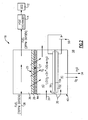
- Figure 2 is a schematic representation of an example fuel stabilization unit including the electrochemical device according to this invention.
- Referring to Figure 1, an example
fuel delivery system 10 is shown and includes afuel stabilization unit 16. Thefuel stabilization unit 16 removes dissolved oxygen from fuel that is supplied to an energy conversion device (ECD) 12. The ECD 12 can be any device that releases energy from the fuel. The ECD 12 can consist of any conversion device known to a worker skilled in the art. One such energy conversion device is a gas turbine engine that includes a compressor that compresses incoming air and combines that compressed incoming air within a combustor to create an air fuel mixture. The air fuel mixture is then ignited and the exhaust gasses are passed through a turbine that in turn powers the combustor. - In the example ECD 12, the fuel serves as a coolant for a
subsystem 24. Aheat exchanger 14 transfers heat generated in thesubsystem 24 to the fuel. Theheat exchanger 14 may be utilized to provide cooling for devices that correspond and operate with the ECD 12. Further theheat exchanger 14 may also be utilized to provide cooling functions for other systems not specifically related to theECD 12. In any of the above cases, the deoxygenation of the fuel increases the capacity for the fuel absorb heat from other systems thereby providing a desired increase in performance. - The
fuel delivery system 10 includes afuel reservoir 18 that contains the supply of fuel for the ECD 12. While stored, the fuel will absorb a large amount of oxygen. The amount of oxygen can be somewhere within the range of approximately 70 parts per million (ppm). Fuel within thereservoir 18 is pumped through apump 20 and regulated by avalve 22 through afuel conduit 26 to thefuel stabilization unit 16. - The
fuel stabilization unit 16 includes an oxygenpermeable membrane 28 and anelectrochemical device 30. Theelectrochemical device 30 promotes reaction of between oxygen, hydrogen ions and electrons to form water. The formation of water removes dissolved oxygen from the non-fuel side 27 (Figure 2) of thepermeable membrane 28, thereby generating the desired oxygen partial pressure differential that draws dissolved oxygen from the fuel. Dissolved oxygen on a non-fuel side of thepermeable membrane 28 is combined with hydrogen to form water. The water is then either consumed by the electrochemical device or routed to areservoir 32 where it can be stored and used for other systems or vented overboard as shown at 34. Oxygen generated in the electrochemical device is vented overboard as shown at 34. - Referring to Figure 2, the
fuel stabilization unit 16 receivesfuel 38 throughconduit 26 from thefuel reservoir 18. This fuel will typically include approximately 70 ppm of dissolved oxygen. Afuel stream 38 flows against a fuel side of apermeable membrane 28. Thepermeable membrane 28 is supported by aporous support structure 44. The total pressure differential between the fuel-side 25 of thepermeable membrane 28 and the non-fuel 27 side determine the strength, thickness and configuration of thesupport structure 44. The greater the total pressure differential across thepermeable membrane 28, the larger and more robust thesupport structure 44. - In the example
fuel stabilization unit 16, achamber 40 is disposed on the non-fuel 27 side of thepermeable membrane 28. Theelectrochemical device 30 and more specifically, the electrolyte of theelectrochemical device 54, separates thechamber 40 into two chambers, 41 and 43. Thechamber 40 is filled with agas 39 such as Nitrogen that contains little oxygen. Theelectrochemical device 30 maintains a low oxygen partial pressure by application of a potential supplied by thepower supply 56. The gas within thechamber 43 may be circulated to improve transfer of oxygen from themembrane 28 to the first electrode 50. Thechamber 43 may also be made thin to bring the membrane and the first electrode into close proximity. The water generated in the first electrode may be absorbed by theelectrolyte 54 or remain in the fuel where it is inert. The electrochemical reaction on thesecond electrode 52 consumes water and produces oxygen. Thegas 39 within thechamber 41 may be circulated to obtain water and vent oxygen. Thechamber 43 includes an overall pressure substantially equal to the pressure exerted against thepermeable membrane 28 on the fuel side. This substantial equalization of pressure across thepermeable membrane 28 provides for the use of a thinner,lighter support structure 44. - Although the overall pressure differential across the
permeable membrane 28 is substantially equal, a partial oxygen pressure differential is still produced to provide the driving force for removal of dissolved oxygen from thefuel stream 38. The oxygen partial pressure differential is provided by converting oxygen within thechamber 43 to water. Once oxygen within thechamber 43 is converted to water, that water is either absorbed by theelectrolyte 54 or used as a reactant on the second electrode, or remains in the fuel stream where it is inert and causes no harm to the operation of theheat exchanger 14 orECD 12. - The elimination of oxygen from within the
chamber 43 generates the desired oxygen partial pressure differential across thepermeable membrane 28 that is required for drawing dissolved oxygen from thefuel stream 38. Accordingly, fuel exiting thefuel stabilization unit 16 will include approximately 2 ppm of oxygen. This reduced level of oxygen within the fuel increases the usable heat absorption capacity of the fuel stream. - The
electrochemical device 30 includes a first electrode 50 and asecond electrode 52 that are powered by abattery 56. Disposed between the first electrode 50 and thesecond electrode 52 is anelectrolyte 54. Theelectrolyte 54 comprises a perflourinated polymer that provides the desired ionic transfer for promoting reaction between dissolved oxygen, hydrogen ions and electrons. On example configuration utilizes a perflourinated polymer known as Nafion in membrane form that is approximately 175 microns thick. As appreciated other materials that provide the desired insulation and ionic transfer properties are also within the contemplation of this invention. - The first electrode 50 is a cathode and is attached to a negative terminal of the
battery 56. Thesecond electrode 52 is an anode and is connected to a positive terminal of thebattery 56. Theelectrodes 50 and 52 are separated from thefuel flow 38 by the oxygenpermeable membrane 28 and therefore are less susceptible to undesirable clogging that may occur when the electrode 50 is disposed adjacent thefuel stream 38. The distance between the oxygenpermeable membrane 28 and the first electrode 50 may be made as small as possible to improve transfer of oxygen through the chamber 42. - The
electrodes 50, 52 andelectrolyte 54 are laminated together to form a mechanical bond that allows ions to transport through the three components of theelectrochemical device 30. - The
electrochemical device 30 promotes the reaction of oxygen with hydrogen ions and electrons within thechamber 43 according to the chemical formula:
- The water generated by the combination of oxygen with hydrogen is disposed within the
chamber 43 and effectively removes oxygen from the non-fuel side of thepermeable membrane 28 to create the desired partial oxygen pressure differential. - Operation of the
fuel stabilization unit 16 is continual such that as the fuel stream flows adjacent the fuel side of thepermeable membrane 28, dissolved oxygen flows through thepermeable membrane 28 and into thechamber 40. Theelectrochemical device 30 continually combines dissolved oxygen with hydrogen ions and electrons on the first electrode 50 to create the oxygen partial pressure differential that draws dissolved oxygen from thefuel stream 38 intochamber 43. Theelectrochemical device 30 continually converts water to oxygen, hydrogen ions and electrons on thesecond electrode 54 inchamber 41. The oxygen produced inchamber 41 is vented to the atmosphere and water required for the reaction is supplied fromreservoir 32. In this way, the electrochemical device with power supplied bybattery 56, serves as an electrochemical oxygen pump. - The example disclosed utilizes the electrolysis of water as the source of hydrogen ions and electrons. However, it is within the contemplation of this invention to utilize other processes. For example, other materials may be supplied by the
reservoir 32 such as a methanol-water mixture: CH3OH + H2O→ CO2+6H++6e- or other compound capable of electrochemical oxidation. In the example utilizing methanol, carbon dioxide is vented instead of oxygen. - The
chamber 43 will include a gas such as nitrogen with little oxygen to begin with. Oxygen from thefuel stream 38 is continually combined with hydrogen ions and electrons in the presence of theelectrochemical device 30 to form water. In other words, oxygen within thechamber 40 is converted to water at a rate that provides a desired oxygen partial pressure differential that will remove the desired amounts of oxygen from the fuel flow. - The
electrochemical device 30 drives this combination of oxygen to hydrogen by way of apower source 56. The exampleelectrochemical device 30 utilizes approximately 13 watts of power at one volt to remove dissolved oxygen from a flow of 250 gallons per hour of fuel. As appreciated, different rates of fuel flow require different amounts of power dependent on the desired oxygen removal rate. A typical voltage is between 0 and 2 volts. - Accordingly, this
fuel stabilization unit 16 provides for the efficient and simple removal of oxygen from a fuel stream without the need of additional complex systems or storage of a strip gas. - Although a preferred embodiment of this invention has been disclosed, a worker of ordinary skill in this art would recognize that certain modifications would come within the scope of this invention. For that reason, the following claims should be studied to determine the true scope and content of this invention.
Claims (15)
- A fuel stabilization unit (16) for removing oxygen from a fuel stream (38) comprising:an oxygen permeable membrane (28) including a fuel side in contact with a fuel stream (38) containing oxygen and a non-fuel side; andan electrochemical device (30) for generating an oxygen partial pressure differential across the permeable membrane (28) for diffusing oxygen from the fuel stream (38).
- The fuel stabilization unit as recited in claim 1, wherein the electrochemical device (30) promotes the combination of oxygen with hydrogen ions and electrons to form water to generate the desired oxygen partial pressure differential.
- The fuel stabilization unit as recited in claim 1 or 2, wherein the electrochemical device (30) comprises a first electrode (50), a second electrode (52) and an electrolyte (54) disposed between the first and second electrodes (50,52).
- The fuel stabilization unit as recited in any preceding claim, including a power source (56) powering the electrochemical device (30).
- The fuel stabilization unit as recited in any preceding claim, including a gas disposed on the non-fuel side of the permeable membrane (28) that contains substantially no oxygen.
- The fuel stabilization unit as recited in claim 5, wherein the gas comprises an inert gas.
- The fuel stabilization unit as recited in claim 5 or 6, wherein the gas comprises a gas inert when exposed to a voltage between 0 and 2 volts.
- The fuel stabilization unit as recited in claim 5, 6 or 7, wherein the gas comprises nitrogen.
- A method of deoxygenating a fuel stream (38) comprising the steps of:a) flowing a fuel stream (38) on a fuel side of an oxygen permeable membrane (28);b) placing a gas (39) on a side of the oxygen permeable membrane (28) opposite from the fuel side; andc) generating an oxygen partial pressure differential across the permeable membrane (28) by promoting a reaction between oxygen, hydrogen ions and electrons to form water on the side of the permeable membrane opposite the fuel side.
- The method as recited in claim 9, including promoting the reaction of oxygen, hydrogen ions and electrons to form water with an electrochemical device (30).
- The method as recited in claim 10, wherein the electrochemical device (30) is disposed on the side of the oxygen permeable membrane (28) opposite the fuel side.
- The method as recited in claim 9, 10 or 11, wherein the electrochemical device (30) comprises a first electrode (50), a second electrode (52) and an electrolyte (54) disposed between the first and second electrode (50,52).
- The method as recited in claim 12, wherein the electrolyte (54) separates a chamber (40) on the side opposite the fuel side into a first chamber (43) adjacent the permeable membrane (28) and a second chamber (41) spaced apart from the permeable membrane (28) by the first chamber (43), wherein oxygen electrochemically removed from the first chamber (43) to the second chamber (41).
- The method as recited in claim 13, including venting the formed oxygen away from the second chamber (41).
- The method as recited in any of claims 9 to 14, including flowing nitrogen gas adjacent a side opposite the fuel- side of the permeable membrane (28).
Applications Claiming Priority (1)
| Application Number | Priority Date | Filing Date | Title |
|---|---|---|---|
| US11/543,535 US7632338B2 (en) | 2006-10-05 | 2006-10-05 | Electrochemical oxygen pump for fuel stabilization unit |
Publications (3)
| Publication Number | Publication Date |
|---|---|
| EP1908506A2 true EP1908506A2 (en) | 2008-04-09 |
| EP1908506A3 EP1908506A3 (en) | 2010-06-30 |
| EP1908506B1 EP1908506B1 (en) | 2014-04-23 |
Family
ID=39000667
Family Applications (1)
| Application Number | Title | Priority Date | Filing Date |
|---|---|---|---|
| EP07253672.5A Active EP1908506B1 (en) | 2006-10-05 | 2007-09-17 | Electrochemical oxygen pump for fuel stabilization unit |
Country Status (2)
| Country | Link |
|---|---|
| US (1) | US7632338B2 (en) |
| EP (1) | EP1908506B1 (en) |
Families Citing this family (25)
| Publication number | Priority date | Publication date | Assignee | Title |
|---|---|---|---|---|
| US8940265B2 (en) | 2009-02-17 | 2015-01-27 | Mcalister Technologies, Llc | Sustainable economic development through integrated production of renewable energy, materials resources, and nutrient regimes |
| US10842645B2 (en) | 2008-08-13 | 2020-11-24 | Smed-Ta/Td, Llc | Orthopaedic implant with porous structural member |
| WO2010019781A1 (en) | 2008-08-13 | 2010-02-18 | Smed-Ta/Td, Llc | Drug delivery implants |
| JP5774989B2 (en) | 2008-08-13 | 2015-09-09 | スメド−ティーエイ/ティーディー・エルエルシー | Orthopedic screw |
| US9700431B2 (en) | 2008-08-13 | 2017-07-11 | Smed-Ta/Td, Llc | Orthopaedic implant with porous structural member |
| US9616205B2 (en) | 2008-08-13 | 2017-04-11 | Smed-Ta/Td, Llc | Drug delivery implants |
| WO2010025386A1 (en) | 2008-08-29 | 2010-03-04 | Smed-Ta/Td, Llc | Orthopaedic implant |
| US9231267B2 (en) * | 2009-02-17 | 2016-01-05 | Mcalister Technologies, Llc | Systems and methods for sustainable economic development through integrated full spectrum production of renewable energy |
| US9097152B2 (en) | 2009-02-17 | 2015-08-04 | Mcalister Technologies, Llc | Energy system for dwelling support |
| US8814983B2 (en) | 2009-02-17 | 2014-08-26 | Mcalister Technologies, Llc | Delivery systems with in-line selective extraction devices and associated methods of operation |
| US8313556B2 (en) * | 2009-02-17 | 2012-11-20 | Mcalister Technologies, Llc | Delivery systems with in-line selective extraction devices and associated methods of operation |
| US8808529B2 (en) * | 2009-02-17 | 2014-08-19 | Mcalister Technologies, Llc | Systems and methods for sustainable economic development through integrated full spectrum production of renewable material resources using solar thermal |
| WO2013147953A1 (en) * | 2011-12-30 | 2013-10-03 | Rolls-Royce North American Technologies Inc. | Aircraft propulsion gas turbine engine with heat exchange |
| US9580185B2 (en) | 2012-01-20 | 2017-02-28 | Hamilton Sundstrand Corporation | Small engine cooled cooling air system |
| EP2969100B1 (en) * | 2013-03-12 | 2018-06-13 | Rolls-Royce North American Technologies, Inc. | Deoxygenation of liquid with gas |
| US10058818B2 (en) | 2014-05-27 | 2018-08-28 | University Of Louisville Research Foundation, Inc. | Pre-treatment of samples by electrochemical removal of dissolved gases |
| US9789972B2 (en) * | 2014-06-27 | 2017-10-17 | Hamilton Sundstrand Corporation | Fuel and thermal management system |
| US20160138539A1 (en) * | 2014-11-18 | 2016-05-19 | Mtd Products Inc | System and method for delivering an additive to fuel in a fuel tank |
| US10215097B2 (en) | 2015-12-08 | 2019-02-26 | General Electric Company | Thermal management system |
| US11071840B2 (en) | 2016-05-13 | 2021-07-27 | Lynntech, Inc. | Hypoxia training device |
| CN106044912A (en) * | 2016-08-05 | 2016-10-26 | 高谦 | Vacuum resolution deoxygenation device |
| US11319085B2 (en) * | 2018-11-02 | 2022-05-03 | General Electric Company | Fuel oxygen conversion unit with valve control |
| US11577852B2 (en) * | 2018-11-02 | 2023-02-14 | General Electric Company | Fuel oxygen conversion unit |
| US11866182B2 (en) * | 2020-05-01 | 2024-01-09 | General Electric Company | Fuel delivery system having a fuel oxygen reduction unit |
| ES2997110T3 (en) * | 2020-12-16 | 2025-02-14 | Airbus Operations Slu | Aircraft and method of operating an aircraft comprising an air separation device |
Citations (2)
| Publication number | Priority date | Publication date | Assignee | Title |
|---|---|---|---|---|
| US4516984A (en) | 1983-11-08 | 1985-05-14 | Emory University | Degassing process and apparatus for removal of oxygen |
| EP1580252A1 (en) | 2004-03-26 | 2005-09-28 | United Technologies Corporation | Electrochemical fuel deoxygenation system |
Family Cites Families (11)
| Publication number | Priority date | Publication date | Assignee | Title |
|---|---|---|---|---|
| US4609383A (en) * | 1984-09-24 | 1986-09-02 | Aquanautics Corporation | Apparatus and method for extracting oxygen from fluids |
| DE3921390A1 (en) * | 1989-06-29 | 1991-01-17 | Merck Patent Gmbh | METHOD AND DEVICE FOR PRODUCING PURE OXYGEN |
| US5122239A (en) * | 1989-07-31 | 1992-06-16 | United Technologies Corporation | Fuel cell product liquid gas stripper |
| US6171368B1 (en) * | 1998-11-06 | 2001-01-09 | Med-E-Cell | Gas extraction from closed containers |
| US6315815B1 (en) | 1999-12-16 | 2001-11-13 | United Technologies Corporation | Membrane based fuel deoxygenator |
| WO2001074710A1 (en) * | 2000-03-30 | 2001-10-11 | Manhattan Scientifics, Inc. | Portable chemical hydrogen hydride system |
| JP2004531640A (en) * | 2001-02-07 | 2004-10-14 | マイクロリス・コーポレイシヨン | Degassing method of aqueous plating solution |
| US6709492B1 (en) * | 2003-04-04 | 2004-03-23 | United Technologies Corporation | Planar membrane deoxygenator |
| CN1261195C (en) * | 2003-10-24 | 2006-06-28 | 深圳奥特迅电气设备有限公司 | Oil-gas separating film, its making process and the gas sensor therewith |
| JP3924791B2 (en) * | 2004-02-20 | 2007-06-06 | 株式会社ジーエス・ユアサコーポレーション | Electrochemical oxygen sensor |
| US7153343B2 (en) * | 2004-03-24 | 2006-12-26 | United Technologies Corporation | Fuel deoxygenation system |
-
2006
- 2006-10-05 US US11/543,535 patent/US7632338B2/en active Active
-
2007
- 2007-09-17 EP EP07253672.5A patent/EP1908506B1/en active Active
Patent Citations (2)
| Publication number | Priority date | Publication date | Assignee | Title |
|---|---|---|---|---|
| US4516984A (en) | 1983-11-08 | 1985-05-14 | Emory University | Degassing process and apparatus for removal of oxygen |
| EP1580252A1 (en) | 2004-03-26 | 2005-09-28 | United Technologies Corporation | Electrochemical fuel deoxygenation system |
Also Published As
| Publication number | Publication date |
|---|---|
| US20080083608A1 (en) | 2008-04-10 |
| EP1908506B1 (en) | 2014-04-23 |
| US7632338B2 (en) | 2009-12-15 |
| EP1908506A3 (en) | 2010-06-30 |
Similar Documents
| Publication | Publication Date | Title |
|---|---|---|
| EP1908506B1 (en) | Electrochemical oxygen pump for fuel stabilization unit | |
| US7431818B2 (en) | Electrochemical fuel deoxygenation system | |
| US5837393A (en) | Fuel battery system | |
| US20050072688A1 (en) | Electrolyzer system to produce gas at high pressure | |
| US7824812B2 (en) | Fuel cell system | |
| EP3800281A1 (en) | Process water gas management of electrolyzer system with pressure differential | |
| JP6617161B2 (en) | Recirculating fuel cell | |
| US20240149083A1 (en) | Process water gas management of electrolyzer system with membrane | |
| JP2007517372A (en) | Fuel cell startup method using fuel purge | |
| JP4877711B2 (en) | Fuel cell system | |
| US20050214617A1 (en) | Non-flammable exhaust enabler for hydrogen powered fuel cells | |
| EP1918424B1 (en) | Electrochemical deoxygenation of fuel by electrolysis | |
| KR102316740B1 (en) | Fuel cell system for a ship | |
| JP2002110207A (en) | Fuel cell system and operating method thereof | |
| JP2010009855A (en) | Fuel cell device | |
| JP4956884B2 (en) | Fuel cell system | |
| US8623562B2 (en) | Method and arrangement to reduce the consumption of safety gas in a fuel cell system | |
| JP2005032600A (en) | Gas-liquid separation system and gas-liquid separation method | |
| JP2003073872A (en) | Water electrolysis facilities | |
| JP2008186800A (en) | Gas-liquid separator and fuel cell device equipped with the same | |
| KR102316750B1 (en) | Fuel cell system for a ship | |
| JP2001283890A (en) | Fuel gas generation system for fuel cells | |
| JP2004307238A (en) | Reformer, fuel cell system using the same, and method for preventing overheating of reformer | |
| JP2004193001A (en) | Fuel cell system | |
| KR100673755B1 (en) | Pump-less fuel cell system |
Legal Events
| Date | Code | Title | Description |
|---|---|---|---|
| PUAI | Public reference made under article 153(3) epc to a published international application that has entered the european phase |
Free format text: ORIGINAL CODE: 0009012 |
|
| AK | Designated contracting states |
Kind code of ref document: A2 Designated state(s): AT BE BG CH CY CZ DE DK EE ES FI FR GB GR HU IE IS IT LI LT LU LV MC MT NL PL PT RO SE SI SK TR |
|
| AX | Request for extension of the european patent |
Extension state: AL BA HR MK RS |
|
| PUAL | Search report despatched |
Free format text: ORIGINAL CODE: 0009013 |
|
| AK | Designated contracting states |
Kind code of ref document: A3 Designated state(s): AT BE BG CH CY CZ DE DK EE ES FI FR GB GR HU IE IS IT LI LT LU LV MC MT NL PL PT RO SE SI SK TR |
|
| AX | Request for extension of the european patent |
Extension state: AL BA HR MK RS |
|
| 17P | Request for examination filed |
Effective date: 20101223 |
|
| AKX | Designation fees paid |
Designated state(s): DE GB |
|
| 17Q | First examination report despatched |
Effective date: 20110426 |
|
| GRAP | Despatch of communication of intention to grant a patent |
Free format text: ORIGINAL CODE: EPIDOSNIGR1 |
|
| INTG | Intention to grant announced |
Effective date: 20130704 |
|
| GRAP | Despatch of communication of intention to grant a patent |
Free format text: ORIGINAL CODE: EPIDOSNIGR1 |
|
| INTG | Intention to grant announced |
Effective date: 20140108 |
|
| GRAS | Grant fee paid |
Free format text: ORIGINAL CODE: EPIDOSNIGR3 |
|
| GRAA | (expected) grant |
Free format text: ORIGINAL CODE: 0009210 |
|
| AK | Designated contracting states |
Kind code of ref document: B1 Designated state(s): DE GB |
|
| REG | Reference to a national code |
Ref country code: GB Ref legal event code: FG4D |
|
| REG | Reference to a national code |
Ref country code: DE Ref legal event code: R096 Ref document number: 602007036218 Country of ref document: DE Effective date: 20140605 |
|
| REG | Reference to a national code |
Ref country code: DE Ref legal event code: R097 Ref document number: 602007036218 Country of ref document: DE |
|
| PLBE | No opposition filed within time limit |
Free format text: ORIGINAL CODE: 0009261 |
|
| STAA | Information on the status of an ep patent application or granted ep patent |
Free format text: STATUS: NO OPPOSITION FILED WITHIN TIME LIMIT |
|
| 26N | No opposition filed |
Effective date: 20150126 |
|
| REG | Reference to a national code |
Ref country code: DE Ref legal event code: R097 Ref document number: 602007036218 Country of ref document: DE Effective date: 20150126 |
|
| REG | Reference to a national code |
Ref country code: DE Ref legal event code: R082 Ref document number: 602007036218 Country of ref document: DE Representative=s name: SCHMITT-NILSON SCHRAUD WAIBEL WOHLFROM PATENTA, DE |
|
| REG | Reference to a national code |
Ref country code: DE Ref legal event code: R082 Ref document number: 602007036218 Country of ref document: DE Representative=s name: SCHMITT-NILSON SCHRAUD WAIBEL WOHLFROM PATENTA, DE Ref country code: DE Ref legal event code: R081 Ref document number: 602007036218 Country of ref document: DE Owner name: UNITED TECHNOLOGIES CORP. (N.D.GES.D. STAATES , US Free format text: FORMER OWNER: UNITED TECHNOLOGIES CORPORATION, HARTFORD, CONN., US |
|
| REG | Reference to a national code |
Ref country code: DE Ref legal event code: R081 Ref document number: 602007036218 Country of ref document: DE Owner name: RAYTHEON TECHNOLOGIES CORPORATION (N.D.GES.D.S, US Free format text: FORMER OWNER: UNITED TECHNOLOGIES CORP. (N.D.GES.D. STAATES DELAWARE), FARMINGTON, CONN., US Ref country code: DE Ref legal event code: R081 Ref document number: 602007036218 Country of ref document: DE Owner name: RTX CORPORATION (N.D.GES.D. STAATES DELAWARE),, US Free format text: FORMER OWNER: UNITED TECHNOLOGIES CORP. (N.D.GES.D. STAATES DELAWARE), FARMINGTON, CONN., US |
|
| P01 | Opt-out of the competence of the unified patent court (upc) registered |
Effective date: 20230519 |
|
| PGFP | Annual fee paid to national office [announced via postgrant information from national office to epo] |
Ref country code: DE Payment date: 20250820 Year of fee payment: 19 |
|
| PGFP | Annual fee paid to national office [announced via postgrant information from national office to epo] |
Ref country code: GB Payment date: 20250827 Year of fee payment: 19 |
|
| REG | Reference to a national code |
Ref country code: DE Ref legal event code: R081 Ref document number: 602007036218 Country of ref document: DE Owner name: RTX CORPORATION (N.D.GES.D. STAATES DELAWARE),, US Free format text: FORMER OWNER: RAYTHEON TECHNOLOGIES CORPORATION (N.D.GES.D.STAATES DELAWARE), ARLINGTON, VA, US |