EP1908401A1 - Method and device for measuring the heartbeat during rythmic sport practice - Google Patents
Method and device for measuring the heartbeat during rythmic sport practice Download PDFInfo
- Publication number
- EP1908401A1 EP1908401A1 EP06121865A EP06121865A EP1908401A1 EP 1908401 A1 EP1908401 A1 EP 1908401A1 EP 06121865 A EP06121865 A EP 06121865A EP 06121865 A EP06121865 A EP 06121865A EP 1908401 A1 EP1908401 A1 EP 1908401A1
- Authority
- EP
- European Patent Office
- Prior art keywords
- movement
- optical signal
- signal
- fundamental frequency
- frequencies
- Prior art date
- Legal status (The legal status is an assumption and is not a legal conclusion. Google has not performed a legal analysis and makes no representation as to the accuracy of the status listed.)
- Ceased
Links
- 238000000034 method Methods 0.000 title claims abstract description 29
- 230000033001 locomotion Effects 0.000 claims abstract description 59
- 230000003287 optical effect Effects 0.000 claims abstract description 51
- 230000001133 acceleration Effects 0.000 claims abstract description 23
- 230000000694 effects Effects 0.000 claims abstract description 15
- 230000005855 radiation Effects 0.000 claims abstract description 11
- 230000003993 interaction Effects 0.000 claims abstract description 6
- 238000005311 autocorrelation function Methods 0.000 claims description 9
- 238000004364 calculation method Methods 0.000 claims description 6
- 230000000737 periodic effect Effects 0.000 claims description 6
- 230000001020 rhythmical effect Effects 0.000 claims description 6
- 238000001514 detection method Methods 0.000 claims description 5
- 230000010351 cardiac pulsation Effects 0.000 claims 1
- 230000010349 pulsation Effects 0.000 abstract description 7
- 238000004422 calculation algorithm Methods 0.000 description 5
- 238000012545 processing Methods 0.000 description 5
- 230000033764 rhythmic process Effects 0.000 description 5
- 238000004458 analytical method Methods 0.000 description 4
- 230000000747 cardiac effect Effects 0.000 description 4
- 238000001914 filtration Methods 0.000 description 4
- 238000005259 measurement Methods 0.000 description 4
- 238000001228 spectrum Methods 0.000 description 3
- 238000007781 pre-processing Methods 0.000 description 2
- 210000000707 wrist Anatomy 0.000 description 2
- 238000010521 absorption reaction Methods 0.000 description 1
- 230000003044 adaptive effect Effects 0.000 description 1
- 239000008280 blood Substances 0.000 description 1
- 210000004369 blood Anatomy 0.000 description 1
- 238000005314 correlation function Methods 0.000 description 1
- 230000001351 cycling effect Effects 0.000 description 1
- 238000011161 development Methods 0.000 description 1
- 238000010586 diagram Methods 0.000 description 1
- 238000009792 diffusion process Methods 0.000 description 1
- 238000000605 extraction Methods 0.000 description 1
- 239000004744 fabric Substances 0.000 description 1
- 238000009532 heart rate measurement Methods 0.000 description 1
- 238000004519 manufacturing process Methods 0.000 description 1
- 238000012067 mathematical method Methods 0.000 description 1
- 238000012986 modification Methods 0.000 description 1
- 230000004048 modification Effects 0.000 description 1
- 238000013186 photoplethysmography Methods 0.000 description 1
- 230000008569 process Effects 0.000 description 1
- 230000001902 propagating effect Effects 0.000 description 1
- 230000000541 pulsatile effect Effects 0.000 description 1
- 230000009467 reduction Effects 0.000 description 1
- 230000009183 running Effects 0.000 description 1
- 239000000523 sample Substances 0.000 description 1
- 230000035945 sensitivity Effects 0.000 description 1
- 230000003068 static effect Effects 0.000 description 1
- 230000009182 swimming Effects 0.000 description 1
- 238000011426 transformation method Methods 0.000 description 1
- 230000009184 walking Effects 0.000 description 1
Images

Classifications
-
- A—HUMAN NECESSITIES
- A61—MEDICAL OR VETERINARY SCIENCE; HYGIENE
- A61B—DIAGNOSIS; SURGERY; IDENTIFICATION
- A61B5/00—Measuring for diagnostic purposes; Identification of persons
- A61B5/02—Detecting, measuring or recording for evaluating the cardiovascular system, e.g. pulse, heart rate, blood pressure or blood flow
- A61B5/024—Measuring pulse rate or heart rate
- A61B5/02416—Measuring pulse rate or heart rate using photoplethysmograph signals, e.g. generated by infrared radiation
-
- A—HUMAN NECESSITIES
- A61—MEDICAL OR VETERINARY SCIENCE; HYGIENE
- A61B—DIAGNOSIS; SURGERY; IDENTIFICATION
- A61B5/00—Measuring for diagnostic purposes; Identification of persons
- A61B5/02—Detecting, measuring or recording for evaluating the cardiovascular system, e.g. pulse, heart rate, blood pressure or blood flow
- A61B5/024—Measuring pulse rate or heart rate
- A61B5/02438—Measuring pulse rate or heart rate with portable devices, e.g. worn by the patient
-
- A—HUMAN NECESSITIES
- A61—MEDICAL OR VETERINARY SCIENCE; HYGIENE
- A61B—DIAGNOSIS; SURGERY; IDENTIFICATION
- A61B5/00—Measuring for diagnostic purposes; Identification of persons
- A61B5/103—Measuring devices for testing the shape, pattern, colour, size or movement of the body or parts thereof, for diagnostic purposes
- A61B5/11—Measuring movement of the entire body or parts thereof, e.g. head or hand tremor or mobility of a limb
- A61B5/1123—Discriminating type of movement, e.g. walking or running
-
- A—HUMAN NECESSITIES
- A61—MEDICAL OR VETERINARY SCIENCE; HYGIENE
- A61B—DIAGNOSIS; SURGERY; IDENTIFICATION
- A61B5/00—Measuring for diagnostic purposes; Identification of persons
- A61B5/68—Arrangements of detecting, measuring or recording means, e.g. sensors, in relation to patient
- A61B5/6801—Arrangements of detecting, measuring or recording means, e.g. sensors, in relation to patient specially adapted to be attached to or worn on the body surface
- A61B5/6802—Sensor mounted on worn items
- A61B5/681—Wristwatch-type devices
-
- A—HUMAN NECESSITIES
- A61—MEDICAL OR VETERINARY SCIENCE; HYGIENE
- A61B—DIAGNOSIS; SURGERY; IDENTIFICATION
- A61B5/00—Measuring for diagnostic purposes; Identification of persons
- A61B5/72—Signal processing specially adapted for physiological signals or for diagnostic purposes
- A61B5/7203—Signal processing specially adapted for physiological signals or for diagnostic purposes for noise prevention, reduction or removal
- A61B5/7207—Signal processing specially adapted for physiological signals or for diagnostic purposes for noise prevention, reduction or removal of noise induced by motion artifacts
- A61B5/721—Signal processing specially adapted for physiological signals or for diagnostic purposes for noise prevention, reduction or removal of noise induced by motion artifacts using a separate sensor to detect motion or using motion information derived from signals other than the physiological signal to be measured
-
- A—HUMAN NECESSITIES
- A61—MEDICAL OR VETERINARY SCIENCE; HYGIENE
- A61B—DIAGNOSIS; SURGERY; IDENTIFICATION
- A61B2562/00—Details of sensors; Constructional details of sensor housings or probes; Accessories for sensors
- A61B2562/02—Details of sensors specially adapted for in-vivo measurements
- A61B2562/0219—Inertial sensors, e.g. accelerometers, gyroscopes, tilt switches
Definitions
- the present invention relates to the field of signal processing. It relates more particularly to a method and an integrated device for measuring a heartbeat during the practice of a rhythmic type of sports activity.
- the heart rhythm measuring devices generally comprise an external probe, fixed for example to the chest or the ear, and connected to a signal processing and display unit. These devices are relatively bulky and inconvenient.
- integrated device a device consisting of a single module performing, at the same point, the measurement of a signal, its processing and the display of the result.
- Such devices are, for example, worn on the wrist as a watch.
- Their operation is based on an optical technique for measuring a physiological data called photoplethysmography (or PPG).
- PPG photoplethysmography
- An optical source emits infrared radiation propagating inside the human tissues in which it undergoes diffusion and absorption. The interaction between radiation and tissues depends on the type and volume of tissue being passed through.
- An optical detector measures the output signal of the tissues. This signal contains information on the tissues crossed. In the absence of movement of the wearer, it comprises a continuous component, derived from the static tissues, and a periodic component, resulting from pulsatile tissues, typically blood. This last component allows the measurement of the heart rate.
- the devices generally include a three-dimensional accelerometer capable of delivering a signal representative of the movement made at the point where the optical signal is measured.
- the present invention is based on a rigorous analysis of the sports movement to provide a method and a device for heart rate detection simplified, robust and efficient.
- the heart rate measurement method according to the invention can be faster, simpler and more robust.
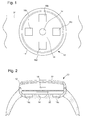
- the integrated device for measuring a heart rate shown schematically in FIGS. 1 and 2 and designated by the general reference 10, conventionally comprises a housing 12 comprising a light source 14 intended to transmit infrared radiation to human tissues, and four photos detectors 16a, 16b, 16c and 16d, such as photodiodes, arranged around the light source 14 so as to receive the infrared radiation after its interaction with the tissues.
- the device 10 also comprises a motion detection system 18, such as a three-dimensional accelerometer, and a processor 20 arranged to receive and process the signals from the photo-detectors 16a, 16b, 16c, 16d, and the accelerometer 18.
- a display module 22, such as an LCD screen, integrated in the housing 12, is intended for displaying the measured physiological parameters, in particular the heart rate.
- the housing 12 is, furthermore, provided with a bracelet 24 for fixing the device 10 to the wrist in the manner of a watch.
- the device 10 is intended for measuring a cardiac rhythm of an athlete practicing a rhythmic type of sport such as walking, running, cycling, swimming etc, or any sport associated with a periodic movement. Its operation is as follows:
- the light source 14 emits infrared radiation that interacts with human tissues.
- the photo-detectors 16a, 16b, 16c and 16d capture an optical signal containing information on the crossed fabrics.
- the accelerometer 18 captures an acceleration signal containing information on the sports movement performed.
- the optical and acceleration signals are processed by the processor 20, in order to extract useful information on a physiological parameter, in particular a heart rate.
- the processor 20 implements an original and efficient signal processing algorithm, based on a careful observation and analysis of the periodic sports movement.
- Such a movement is globally complex. It is formed of a combination of sub-movements: the sub-movements of the legs, arms, torso, etc. It has been observed, in the context of the present invention, that each of these sub-movements is harmonic type, that is to say characterized by a fundamental frequency f 0 , and harmonic frequencies f 1 , f 2 , ... f i , multiples of the fundamental frequency f 0 . Moreover, the sub-movements are not independent of each other: Their fundamental frequencies are themselves multiple of each other, so that the global movement is a harmonic movement of fundamental frequency the smallest of the fundamental frequencies of the various sub -mouvements. Such an observation greatly simplifies the processing of the acceleration signal.
- the algorithm according to the invention is based on the preceding analysis. It comprises three main blocks respectively pretreatment 100, enhancement of the optical signal 200, and estimation of the heartbeat 300, each comprising a number of sub-blocks, and detailed below.
- the optical and acceleration signals respectively coming from the photodetectors 16a, 16b, 16c, 16d, and from the accelerometer 18, are first subjected to a pretreatment, symbolized respectively by two sub-blocks 101 and 102 belonging to the module 100.
- the pretreatment 101 generally consists, for the optical signal, in a first step of removing the DC component of the signal, followed by a second filtering step to reduce the frequency range to values compatible with a heart rate.
- the acceleration signal it is essentially during the preprocessing step 102 to the removal of the DC component. Note that the pretreatment of optical and acceleration signals can be performed in analog or digital mode.
- the module for raising the optical signal 200 comprises a first sub-block 201 for determining the fundamental frequency of the movement from the pre-processed acceleration signal, according to the basic idea of the present invention that the extraction of this single parameter is necessary.
- the autocorrelation function will advantageously be used for estimating the fundamental frequency of the movement.
- the spectrum of the autocorrelation function of a signal is equivalent to the power spectrum of the original signal.
- the sub-block 201 for determining the fundamental frequency thus proceeds, in a first step, to the calculation of the auto-correlation function of the acceleration signal, then, in a second step, to the detection of the maximum of the function. autocorrelation.
- a polynomial approximation of the autocorrelation function around the maximum in order to increase the resolution of the detection of the maximum and the precision of the result, one can perform, within the sub-block 201, a polynomial approximation of the autocorrelation function around the maximum.
- any other mathematical method for determining the fundamental frequency f 0 of the movement is usable.
- transformation methods such as Fourier transform (FFT), cosine transform (DCT), or parametric methods.
- FFT Fourier transform
- DCT cosine transform
- parametric methods are not limited to the calculation of the useful parameter, the fundamental frequency f 0 , but, on the contrary, relate to a large number of parameters. They are inherently heavy, and require considerable computing power. This is why the calculation of the fundamental frequency f 0 by the autocorrelation function is to be preferred.
- a second sub-block 202 relates to the calculation of the harmonics f 1 , f 2 , ... f i . Harmonics are obtained by simple multiplication of the fundamental frequency f 0 by natural numbers (1, 2, 3, ).
- a third sub-block 203 follows the sub-block 202 for calculating harmonics.
- This sub-block 203 relates to the development of a comb filter as illustrated in FIG. 4.
- Such a filter conventionally comprises wide bandwidths 50 and narrow rejection bands 52 centered on the fundamental frequency f 0. of the movement and its harmonics f 1 , f 2 , ... f i .
- the width of the rejection bands is non-zero and fixed by a set of parameters ( ⁇ 0 , ⁇ 1 , ⁇ 2 , ... ⁇ i ).
- the set of parameters ⁇ i is determined for a given activity.
- ⁇ i parameters refer to the joint application entitled 'Method and Integrated Heartbeat Measurement Device' filed on 06 October 2006 on behalf of ETA SA Manufacture Horlogère Suisse.
- a sub-block 204 for filtering the optical signal is connected on the one hand to the block 205 for producing the comb filter and on the other hand to the sub-block 101 for preprocessing the optical signal. It corresponds to the operation of filtering the optical signal using the comb filter developed from the frequencies f i of the movement. After the filtering operation performed at 204, motion related artifacts are removed from the optical signal.
- the enhanced optical signal is filtered using an adaptive bandpass filter or a PCA noise reduction algorithm as described in the patent. US 7,018,338 . Then, the heartbeat is estimated from the filtered enhanced optical signal.
- the zero-crossing method in English terminology, that is to say, the zero crossing method, well known to those skilled in the art.
- a device and a method for measuring a heartbeat whose performance has been increased by means of an optical signal enhancement method based on a thorough analysis of the periodic sports movement have been described.
Landscapes
- Health & Medical Sciences (AREA)
- Life Sciences & Earth Sciences (AREA)
- Engineering & Computer Science (AREA)
- General Health & Medical Sciences (AREA)
- Veterinary Medicine (AREA)
- Biophysics (AREA)
- Biomedical Technology (AREA)
- Heart & Thoracic Surgery (AREA)
- Medical Informatics (AREA)
- Molecular Biology (AREA)
- Surgery (AREA)
- Animal Behavior & Ethology (AREA)
- Physics & Mathematics (AREA)
- Public Health (AREA)
- Pathology (AREA)
- Physiology (AREA)
- Cardiology (AREA)
- Signal Processing (AREA)
- Dentistry (AREA)
- Oral & Maxillofacial Surgery (AREA)
- Artificial Intelligence (AREA)
- Computer Vision & Pattern Recognition (AREA)
- Psychiatry (AREA)
- Measuring Pulse, Heart Rate, Blood Pressure Or Blood Flow (AREA)
Abstract
Description
La présente invention se rapporte au domaine du traitement du signal. Elle concerne plus particulièrement une méthode et un dispositif intégré de mesure d'une pulsation cardiaque durant la pratique d'une activité sportive de type rythmique.The present invention relates to the field of signal processing. It relates more particularly to a method and an integrated device for measuring a heartbeat during the practice of a rhythmic type of sports activity.
Les dispositifs de mesure du rythme cardiaque comportent généralement une sonde externe, fixée, par exemple, à la poitrine ou à l'oreille, et connectée à une unité de traitement du signal et d'affichage. Ces dispositifs sont relativement encombrants et incommodes.The heart rhythm measuring devices generally comprise an external probe, fixed for example to the chest or the ear, and connected to a signal processing and display unit. These devices are relatively bulky and inconvenient.
Récemment, des dispositifs intégrés ont fait leur apparition. Par dispositif intégré, on entend un dispositif formé d'un unique module effectuant, au même point, la mesure d'un signal, son traitement et l'affichage du résultat. De tels dispositifs sont, par exemple, portés au poignet à la façon d'une montre. Leur fonctionnement est basé sur une technique optique de mesure d'une donnée physiologique appelée photoplethysmographie (ou PPG). Le principe en est le suivant : Une source optique émet un rayonnement infrarouge se propageant à l'intérieur des tissus humains dans lesquels il subit de la diffusion et de l'absorption. L'interaction entre le rayonnement et les tissus dépend du type et du volume de tissu traversé. Un détecteur optique mesure le signal en sortie des tissus. Ce signal contient une information sur les tissus traversés. En l'absence de mouvement du porteur, il comporte une composante continue, issue des tissus statiques, et une composante périodique, issue des tissus pulsatiles, typiquement le sang. Cette dernière composante permet la mesure du rythme cardiaque.Recently, integrated devices have appeared. By integrated device is meant a device consisting of a single module performing, at the same point, the measurement of a signal, its processing and the display of the result. Such devices are, for example, worn on the wrist as a watch. Their operation is based on an optical technique for measuring a physiological data called photoplethysmography (or PPG). The principle is as follows: An optical source emits infrared radiation propagating inside the human tissues in which it undergoes diffusion and absorption. The interaction between radiation and tissues depends on the type and volume of tissue being passed through. An optical detector measures the output signal of the tissues. This signal contains information on the tissues crossed. In the absence of movement of the wearer, it comprises a continuous component, derived from the static tissues, and a periodic component, resulting from pulsatile tissues, typically blood. This last component allows the measurement of the heart rate.
Un inconvénient lié à la méthode de mesure du rythme cardiaque par PPG est sa sensibilité aux mouvements du sujet sur lequel la mesure est pratiquée. Ces mouvements génèrent des artefacts dont la contribution au signal excède souvent la contribution utile de la pulsation cardiaque, d'un ordre de grandeur. Le signal optique doit ainsi être traité de manière à éliminer la contribution due aux mouvements. On parle de rehaussement du signal optique. A cet effet, les dispositifs intègrent généralement un accéléromètre à trois dimensions apte à délivrer un signal représentatif du mouvement effectué au point où le signal optique est mesuré.A disadvantage of PPG's method of measuring cardiac rhythm is its sensitivity to the movements of the subject on which the measurement is made. These movements generate artifacts whose contribution to the signal often exceeds the useful contribution of the heartbeat, by an order of magnitude. The optical signal must thus be processed so as to eliminate the contribution due to the movements. We talk about raising the optical signal. For this purpose, the devices generally include a three-dimensional accelerometer capable of delivering a signal representative of the movement made at the point where the optical signal is measured.
Différentes méthodes de rehaussement du signal optique à l'aide du signal d'accélération ont été divulguées à ce jour. On citera, par exemple, le document
De telles méthodes de rehaussement du signal optique sont extrêmement lourdes et nécessitent une puissance de calcul considérable. Pour des questions de coût et d'encombrement, des solutions plus simples sont à privilégier. La présente invention se base sur une analyse rigoureuse du mouvement sportif pour proposer une méthode et un dispositif de détection du rythme cardiaque simplifiés, robustes et performants.Such methods of raising the optical signal are extremely heavy and require considerable computing power. For issues of cost and size, simpler solutions are preferred. The present invention is based on a rigorous analysis of the sports movement to provide a method and a device for heart rate detection simplified, robust and efficient.
Plus précisément, l'invention concerne une méthode de mesure d'une pulsation cardiaque durant une activité sportive de type rythmique impliquant un mouvement périodique, consistant principalement à :
- transmettre un rayonnement lumineux dans des tissus organiques,
- détecter un signal optique issu de l'interaction dudit rayonnement lumineux avec les tissus organiques, le signal optique comprenant une composante relative à la pulsation cardiaque et une composante relative au mouvement effectué durant l'activité sportive,
- détecter un signal d'accélération contenant une indication relative au mouvement effectué durant l'activité sportive,
- effectuer un rehaussement du signal optique de manière à en éliminer la composante relative au mouvement effectué, et
- calculer la pulsation cardiaque à partir du signal optique ainsi rehaussé,
- transmit light radiation in organic tissues,
- detecting an optical signal resulting from the interaction of said light radiation with the organic tissues, the optical signal comprising a component relating to the heartbeat and a component relating to the movement performed during the sports activity,
- detecting an acceleration signal containing an indication of the movement made during the sport activity,
- perform an enhancement of the optical signal so as to eliminate the component relating to the movement made, and
- calculate the heartbeat from the optical signal thus enhanced,
Selon l'invention, le rehaussement du signal optique comprend principalement les étapes suivantes :
- déterminer la fréquence fondamentale du mouvement,
- déterminer les harmoniques correspondant à la fréquence fondamentale, et
- éliminer les fréquences ainsi déterminées du signal optique.
- determine the fundamental frequency of the movement,
- determine the harmonics corresponding to the fundamental frequency, and
- eliminate the frequencies thus determined from the optical signal.
Grâce à ces caractéristiques, la méthode de mesure du rythme cardiaque selon l'invention peut gagner en rapidité, en simplicité et en robustesse.Thanks to these characteristics, the heart rate measurement method according to the invention can be faster, simpler and more robust.
L'invention concerne également un dispositif intégré de mesure d'une pulsation cardiaque durant une activité sportive de type rythmique, pour la mise en oeuvre d'une telle méthode, comportant :
- une source lumineuse,
- un photo-détecteur fournissant un signal optique comprenant une composante relative à la pulsation cardiaque et une composante relative au mouvement effectué durant l'activité sportive,
- un accéléromètre fournissant un signal d'accélération contenant une indication relative au mouvement effectué durant l'activité sportive, et
- un processeur apte à effectuer un rehaussement du signal optique de manière à en éliminer la composante relative au mouvement effectué, et calculer la pulsation cardiaque à partir du signal optique rehaussé,
- déterminer une fréquence fondamentale du mouvement à partir du signal d'accélération,
- déterminer des fréquences harmoniques du mouvement, et
- éliminer du signal optique les fréquences du mouvement déterminées.
- a light source,
- a photodetector providing an optical signal comprising a component relating to the heartbeat and a component relating to the movement performed during the sports activity,
- an accelerometer providing an acceleration signal containing an indication of movement during the sporting activity, and
- a processor adapted to perform an enhancement of the optical signal so as to eliminate the component relating to the movement performed, and calculate the heart rate from the enhanced optical signal,
- determine a fundamental frequency of the movement from the acceleration signal,
- determine harmonic frequencies of the movement, and
- to eliminate from the optical signal the determined frequencies of the movement.
D'autres caractéristiques et avantages de la présente invention ressortiront plus clairement de la description détaillée qui suit d'un exemple de réalisation d'un dispositif de mesure d'un rythme cardiaque selon l'invention, cet exemple étant donné à titre purement illustratif et non limitatif seulement, en liaison avec le dessin annexé sur lequel :
- les figures 1 et 2 sont des vues respectivement de dessous et en coupe du dispositif selon l'invention,
- la figure 3 est un diagramme illustrant un algorithme de calcul du rythme cardiaque utilisé par le dispositif selon l'invention, et
- la figure 4 se rapporte à une étape de l'algorithme représenté en figure 3.
- FIGS. 1 and 2 are respectively views from below and in section of the device according to the invention,
- FIG. 3 is a diagram illustrating an algorithm for calculating the cardiac rhythm used by the device according to the invention, and
- Figure 4 relates to a step of the algorithm shown in Figure 3.
Le dispositif intégré de mesure d'un rythme cardiaque représenté schématiquement sur les figures 1 et 2 et désigné par la référence générale 10, comporte classiquement un boîtier 12 comprenant une source lumineuse 14 destinée à transmettre un rayonnement infrarouge à des tissus humains, et quatre photo-détecteurs 16a, 16b, 16c et 16d, tels que des photodiodes, disposés autour de la source lumineuse 14 de manière à recevoir le rayonnement infrarouge après son interaction avec les tissus. Le dispositif 10 comporte également un système de détection du mouvement 18, tel qu'un accéléromètre à trois dimensions, et un processeur 20 agencé pour recevoir et traiter les signaux issus des photo-détecteurs 16a, 16b, 16c, 16d, et de l'accéléromètre 18. Un module d'affichage 22, tel qu'un écran LCD, intégré au boîtier 12, est destiné à l'affichage des paramètres physiologiques mesurés, en particulier du rythme cardiaque. Le boîtier 12 est, en outre, muni d'un bracelet 24 pour la fixation du dispositif 10 au poignet à la façon d'une montre.The integrated device for measuring a heart rate shown schematically in FIGS. 1 and 2 and designated by the
Le dispositif 10 est destiné à la mesure d'un rythme cardiaque d'un sportif pratiquant un sport de type rythmique tel que la marche, la course à pied, le cyclisme, la natation etc, ou tout sport associé à un mouvement périodique. Son fonctionnement est le suivant : La source lumineuse 14 émet un rayonnement infrarouge qui interagit avec les tissus humains. Les photo-détecteurs 16a, 16b, 16c et 16d captent un signal optique contenant une information sur les tissus traversés. Parallèlement, l'accéléromètre 18 capte un signal d'accélération contenant une information sur le mouvement sportif effectué. Les signaux optique et d'accélération sont traités par le processeur 20, en vue d'extraire une information utile sur un paramètre physiologique, en particulier un rythme cardiaque. A cet effet, le processeur 20 met en oeuvre un algorithme de traitement du signal original et performant, fondé sur une observation et une analyse minutieuses du mouvement sportif périodique.The
Un tel mouvement est globalement complexe. Il est formé d'une combinaison de sous-mouvements : les sous-mouvements des jambes, des bras, du torse etc...II a été observé, dans le cadre de la présente invention, que chacun de ces sous-mouvements est de type harmonique, c'est-à-dire caractérisé par une fréquence fondamentale f0, et des fréquences harmoniques f1, f2, ... fi, multiples de la fréquence fondamentale f0. De plus, les sous-mouvements ne sont pas indépendants les uns des autres : Leurs fréquences fondamentales sont elles même multiples les unes des autres, de sorte que le mouvement global est un mouvement harmonique de fréquence fondamentale la plus petite des fréquences fondamentales des différents sous-mouvements. Une telle observation simplifie considérablement le traitement du signal d'accélération. En effet, il s'avère suffisant, sur la base de cette observation, de déterminer la fréquence fondamentale f0 du mouvement sportif, pour obtenir l'ensemble des fréquences du mouvement par simple multiplication. Le calcul d'un spectre en fréquence complet du signal d'accélération, est ainsi inutilement lourd et complexe, et sa forte consommation en puissance de calcul est injustifiée.Such a movement is globally complex. It is formed of a combination of sub-movements: the sub-movements of the legs, arms, torso, etc. It has been observed, in the context of the present invention, that each of these sub-movements is harmonic type, that is to say characterized by a fundamental frequency f 0 , and harmonic frequencies f 1 , f 2 , ... f i , multiples of the fundamental frequency f 0 . Moreover, the sub-movements are not independent of each other: Their fundamental frequencies are themselves multiple of each other, so that the global movement is a harmonic movement of fundamental frequency the smallest of the fundamental frequencies of the various sub -mouvements. Such an observation greatly simplifies the processing of the acceleration signal. Indeed, it is sufficient, on the basis of this observation, to determine the fundamental frequency f 0 of the sporting movement, to obtain all the frequencies of the movement by simple multiplication. The calculation of a complete frequency spectrum of the acceleration signal is thus unnecessarily cumbersome and complex, and its high power consumption is unjustified.
On notera toutefois que seul un mouvement global idéal est rigoureusement harmonique. Dans le cas réel, le mouvement global est sensiblement harmonique car les fréquences fondamentales des différents sous-mouvements ne sont pas rigoureusement multiples les unes des autres, et de petites variations existent. On verra dans la suite de cet exposé, comment de telles variations sont prises en compte dans l'estimation de la pulsation cardiaque.It should be noted, however, that only an ideal global movement is strictly harmonic. In the real case, the global motion is substantially harmonic because the fundamental frequencies of the different sub-movements are not rigorously multiple of each other, and small variations exist. We will see in the following of this presentation, how such variations are taken into account in the estimation of the heartbeat.
L'algorithme selon l'invention, illustré schématiquement en figure 3, est basé sur l'analyse précédente. Il comprend trois blocs principaux respectivement de prétraitement 100, de rehaussement du signal optique 200, et d'estimation de la pulsation cardiaque 300, comportant chacun un certain nombre de sous-blocs, et détaillés ci-dessous.The algorithm according to the invention, schematically illustrated in FIG. 3, is based on the preceding analysis. It comprises three main blocks respectively
Les signaux optique et d'accélération issus respectivement des photo-détecteurs 16a, 16b, 16c, 16d, et de l'accéléromètre 18, subissent en premier lieu un prétraitement, symbolisé respectivement par deux sous-blocs 101 et 102 appartenant au module 100. Le prétraitement 101 consiste généralement, pour le signal optique, en une première étape d'élimination de la composante continue du signal, suivie d'une deuxième étape de filtrage en vue de réduire le domaine de fréquences aux valeurs compatibles avec un rythme cardiaque. Concernant le signal d'accélération, on procède essentiellement lors de l'étape de prétraitement 102 à la suppression de la composante continue. On notera que le prétraitement des signaux optique et d'accélération peut être effectué en mode analogique ou numérique.The optical and acceleration signals respectively coming from the
Le module de rehaussement du signal optique 200 comporte un premier sous-bloc 201 de détermination de la fréquence fondamentale du mouvement à partir du signal d'accélération prétraité, selon l'idée de base de la présente invention que l'extraction de ce seul paramètre est nécessaire.The module for raising the
On utilisera avantageusement pour l'estimation de la fréquence fondamentale du mouvement, la fonction d'auto-corrélation, bien connue de l'homme de métier. D'après le théorème de Wiener-Khintchine, le spectre de la fonction d'auto-corrélation d'un signal est équivalent au spectre de puissance du signal original. Autrement dit, la fonction d'auto-corrélation d'un signal contient la même information fréquentielle que le signal d'origine sans l'information de la phase. En conséquence, pour un signal harmonique, dont les fréquences fi sont des multiples de la fréquence fondamentale f0, la fonction d'auto-corrélation rγγ du signal peut s'écrire sous la forme suivante : 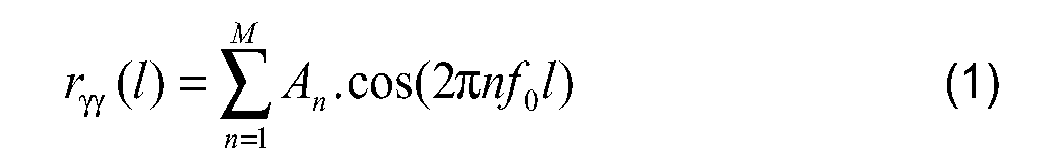
II ressort de l'équation (1) que la fonction d'auto-corrélation d'un signal harmonique, et en particulier la fonction d'auto-corrélation rγγ du signal d'accélération, présente un maximum en I = 1/f0, où f0 est la fréquence fondamentale du signal.It follows from equation (1) that the auto-correlation function of a harmonic signal, and in particular the auto-correlation function r γγ of the acceleration signal, has a maximum in I = 1 / f 0 , where f 0 is the fundamental frequency of the signal.
Le sous-bloc 201 de détermination de la fréquence fondamentale procède donc, dans une première étape, au calcul de la fonction d'auto-corrélation du signal d'accélération, puis, dans une seconde étape, à la détection du maximum de la fonction d'auto-corrélation. Dans certains cas, afin d'augmenter la résolution de la détection du maximum et la précision du résultat, on peut effectuer, à l'intérieur du sous-bloc 201, une approximation polynômiale de la fonction d'auto-corrélation autour du maximum.The sub-block 201 for determining the fundamental frequency thus proceeds, in a first step, to the calculation of the auto-correlation function of the acceleration signal, then, in a second step, to the detection of the maximum of the function. autocorrelation. In some cases, in order to increase the resolution of the detection of the maximum and the precision of the result, one can perform, within the sub-block 201, a polynomial approximation of the autocorrelation function around the maximum.
Bien entendu, toute autre méthode mathématique permettant de déterminer la fréquence fondamentale f0 du mouvement est utilisable. On citera, par exemple, les méthodes de transformation telles que la transformation de Fourier (FFT), la transformation de cosinus (DCT), ou les méthodes paramétriques. Toutefois, ces méthodes ne se limitent pas au calcul du paramètre utile, la fréquence fondamentale f0, mais, au contraire, portent sur un grand nombre de paramètres. Elles sont par nature lourdes, et nécessitent une puissance de calcul considérable. C'est pourquoi, le calcul de la fréquence fondamentale f0 par la fonction d'auto-corrélation est à privilégier.Of course, any other mathematical method for determining the fundamental frequency f 0 of the movement is usable. Examples include transformation methods such as Fourier transform (FFT), cosine transform (DCT), or parametric methods. However, these methods are not limited to the calculation of the useful parameter, the fundamental frequency f 0 , but, on the contrary, relate to a large number of parameters. They are inherently heavy, and require considerable computing power. This is why the calculation of the fundamental frequency f 0 by the autocorrelation function is to be preferred.
A la suite du sous-bloc 201 de détermination de la fréquence fondamentale f0, un deuxième sous-bloc 202 concerne le calcul des harmoniques f1, f2,... fi. Les harmoniques sont obtenues par simple multiplication de la fréquence fondamentale f0 par des entiers naturels (1, 2, 3, ...).Following the sub-block 201 for determining the fundamental frequency f 0 , a
Un troisième sous-bloc 203 fait suite au sous-bloc 202 de calcul des harmoniques. Ce sous-bloc 203 se rapporte à l'élaboration d'un filtre en peigne tel qu'illustré en figure 4. Un tel filtre comporte classiquement de larges bandes passantes 50 et d'étroites bandes de réjection 52 centrées sur la fréquence fondamentale f0 du mouvement et ses harmoniques f1, f2,...fi. La largeur des bandes de réjection est non nulle et fixée par un jeu de paramètres (β0, β1, β2, ... βi). Les paramètres (β0, β1, β2, ...βi) du filtre en peigne permettent de prendre en compte les petites variations de la fréquence fondamentale et des fréquences harmoniques dues à l'imperfection du mouvement global réel. Avantageusement, le jeu de paramètres βi est déterminé pour une activité donnée. Pour plus de précisions sur les paramètres βi, on se reportera à la demande conjointe intitulée 'Méthode et dispositif intégré de mesure d'une pulsation cardiaque' déposée en date du 06 Octobre 2006 au nom de ETA S.A. Manufacture Horlogère Suisse.A
Enfin, un sous-bloc 204 de filtrage du signal optique, est relié d'une part au bloc 203 d'élaboration du filtre en peigne, et d'autre part, au sous-bloc 101 de prétraitement du signal optique. Il correspond à l'opération de filtrage du signal optique à l'aide du filtre en peigne élaboré à partir des fréquences fi du mouvement. Après l'opération de filtrage réalisée en 204, les artefacts liés au mouvement sont éliminés du signal optique.Finally, a sub-block 204 for filtering the optical signal is connected on the one hand to the block 205 for producing the comb filter and on the other hand to the sub-block 101 for preprocessing the optical signal. It corresponds to the operation of filtering the optical signal using the comb filter developed from the frequencies f i of the movement. After the filtering operation performed at 204, motion related artifacts are removed from the optical signal.
Le signal optique rehaussé est filtré, à l'aide d'un filtre passe-bande adaptatif, ou d'un algorithme de réduction du bruit de type PCA tel que décrit dans le brevet
On a ainsi décrit un dispositif et une méthode de mesure d'une pulsation cardiaque dont les performances sont augmentées grâce à une méthode de rehaussement du signal optique basée sur une analyse poussée du mouvement sportif périodique.A device and a method for measuring a heartbeat whose performance has been increased by means of an optical signal enhancement method based on a thorough analysis of the periodic sports movement have been described.
Bien entendu, la méthode et le dispositif selon l'invention ne se limitent pas au mode de réalisation qui vient d'être décrit et diverses modifications et variantes simples peuvent être envisagées par l'homme du métier sans sortir du cadre de l'invention tel que défini par les revendications annexées.Of course, the method and the device according to the invention are not limited to the embodiment which has just been described and various simple modifications and variants can be envisaged by those skilled in the art without departing from the scope of the invention. as defined by the appended claims.
Claims (6)
Priority Applications (3)
| Application Number | Priority Date | Filing Date | Title |
|---|---|---|---|
| EP06121865A EP1908401A1 (en) | 2006-10-06 | 2006-10-06 | Method and device for measuring the heartbeat during rythmic sport practice |
| PCT/EP2007/060467 WO2008040735A1 (en) | 2006-10-06 | 2007-10-02 | Method and device for measuring a heart pulsation when practising a rythmical sport |
| TW96137269A TW200833297A (en) | 2006-10-06 | 2007-10-04 | Method and integrated device for measuring a cardiac pulsation for practising a rhythmical sport |
Applications Claiming Priority (1)
| Application Number | Priority Date | Filing Date | Title |
|---|---|---|---|
| EP06121865A EP1908401A1 (en) | 2006-10-06 | 2006-10-06 | Method and device for measuring the heartbeat during rythmic sport practice |
Publications (1)
| Publication Number | Publication Date |
|---|---|
| EP1908401A1 true EP1908401A1 (en) | 2008-04-09 |
Family
ID=37873069
Family Applications (1)
| Application Number | Title | Priority Date | Filing Date |
|---|---|---|---|
| EP06121865A Ceased EP1908401A1 (en) | 2006-10-06 | 2006-10-06 | Method and device for measuring the heartbeat during rythmic sport practice |
Country Status (3)
| Country | Link |
|---|---|
| EP (1) | EP1908401A1 (en) |
| TW (1) | TW200833297A (en) |
| WO (1) | WO2008040735A1 (en) |
Cited By (8)
| Publication number | Priority date | Publication date | Assignee | Title |
|---|---|---|---|---|
| WO2013038296A1 (en) * | 2011-09-16 | 2013-03-21 | Koninklijke Philips Electronics N.V. | Device and method for estimating the heart rate during motion |
| WO2013128345A1 (en) * | 2012-02-28 | 2013-09-06 | Koninklijke Philips N.V. | Device and method for monitoring vital signs |
| WO2014091382A1 (en) * | 2012-12-14 | 2014-06-19 | Koninklijke Philips N.V. | A system and method to detect significant arrhythmic events through a photoplethysmogram (ppg) and accelerometer |
| WO2015128226A1 (en) * | 2014-02-26 | 2015-09-03 | Koninklijke Philips N.V. | Device for measuring a cycling cadence |
| EP3600013A4 (en) * | 2017-03-23 | 2020-12-09 | Valencell, Inc. | PHYSIOLOGICAL MONITORING DEVICES AND METHODS OF NOISE REDUCTION FOR PHYSIOLOGICAL SIGNALS BASED ON PERSONAL ACTIVITY TYPE |
| US10945618B2 (en) | 2015-10-23 | 2021-03-16 | Valencell, Inc. | Physiological monitoring devices and methods for noise reduction in physiological signals based on subject activity type |
| US10966662B2 (en) | 2016-07-08 | 2021-04-06 | Valencell, Inc. | Motion-dependent averaging for physiological metric estimating systems and methods |
| US11375902B2 (en) | 2011-08-02 | 2022-07-05 | Valencell, Inc. | Systems and methods for variable filter adjustment by heart rate metric feedback |
Families Citing this family (3)
| Publication number | Priority date | Publication date | Assignee | Title |
|---|---|---|---|---|
| EP2229880A1 (en) * | 2009-03-18 | 2010-09-22 | CSEM Centre Suisse d'Electronique et de Microtechnique SA | Headband integrated monitoring unit using an accelerometer |
| JP5672709B2 (en) | 2010-02-04 | 2015-02-18 | セイコーエプソン株式会社 | Biological information detector, biological information measuring device, and method for designing reflector in biological information detector |
| TWI608826B (en) * | 2014-10-31 | 2017-12-21 | 財團法人工業技術研究院 | Optical sensing device and measurement method thereof |
Citations (7)
| Publication number | Priority date | Publication date | Assignee | Title |
|---|---|---|---|---|
| EP0659384A1 (en) * | 1993-12-20 | 1995-06-28 | Seiko Instruments Inc. | Pulse rate monitor |
| EP0922433A1 (en) * | 1997-03-17 | 1999-06-16 | Seiko Epson Corporation | Pulse wave detector and pulsimeter |
| EP0941694A1 (en) * | 1997-09-05 | 1999-09-15 | Seiko Epson Corporation | Reflection photodetector and biological information measuring instrument |
| US20030138763A1 (en) * | 2002-01-23 | 2003-07-24 | Aquatech Fitness Corp. | System for monitoring repetitive movement |
| US20040236233A1 (en) * | 2003-03-19 | 2004-11-25 | Seiko Epson Corporation | Information-gathering device and pulse meter |
| US7018338B2 (en) | 2001-09-28 | 2006-03-28 | Csem Centre Suisse D'electronique Et De Microtechnique Sa | Method and device for pulse rate detection |
| WO2006044677A1 (en) | 2004-10-15 | 2006-04-27 | Pulsetracer Technologies Inc. | Motion cancellation of optical input signals for physiological pulse measurement |
-
2006
- 2006-10-06 EP EP06121865A patent/EP1908401A1/en not_active Ceased
-
2007
- 2007-10-02 WO PCT/EP2007/060467 patent/WO2008040735A1/en not_active Ceased
- 2007-10-04 TW TW96137269A patent/TW200833297A/en unknown
Patent Citations (7)
| Publication number | Priority date | Publication date | Assignee | Title |
|---|---|---|---|---|
| EP0659384A1 (en) * | 1993-12-20 | 1995-06-28 | Seiko Instruments Inc. | Pulse rate monitor |
| EP0922433A1 (en) * | 1997-03-17 | 1999-06-16 | Seiko Epson Corporation | Pulse wave detector and pulsimeter |
| EP0941694A1 (en) * | 1997-09-05 | 1999-09-15 | Seiko Epson Corporation | Reflection photodetector and biological information measuring instrument |
| US7018338B2 (en) | 2001-09-28 | 2006-03-28 | Csem Centre Suisse D'electronique Et De Microtechnique Sa | Method and device for pulse rate detection |
| US20030138763A1 (en) * | 2002-01-23 | 2003-07-24 | Aquatech Fitness Corp. | System for monitoring repetitive movement |
| US20040236233A1 (en) * | 2003-03-19 | 2004-11-25 | Seiko Epson Corporation | Information-gathering device and pulse meter |
| WO2006044677A1 (en) | 2004-10-15 | 2006-04-27 | Pulsetracer Technologies Inc. | Motion cancellation of optical input signals for physiological pulse measurement |
Cited By (18)
| Publication number | Priority date | Publication date | Assignee | Title |
|---|---|---|---|---|
| US11375902B2 (en) | 2011-08-02 | 2022-07-05 | Valencell, Inc. | Systems and methods for variable filter adjustment by heart rate metric feedback |
| WO2013038296A1 (en) * | 2011-09-16 | 2013-03-21 | Koninklijke Philips Electronics N.V. | Device and method for estimating the heart rate during motion |
| US10617308B2 (en) | 2011-09-16 | 2020-04-14 | Koninklijke Philips N.V. | Device and method for estimating the heart rate during motion |
| US9770176B2 (en) | 2011-09-16 | 2017-09-26 | Koninklijke Philips N.V. | Device and method for estimating the heart rate during motion |
| JP2015511499A (en) * | 2012-02-28 | 2015-04-20 | コーニンクレッカ フィリップス エヌ ヴェ | Device and method for monitoring vital signs |
| US10542925B2 (en) | 2012-02-28 | 2020-01-28 | Koninklijke Philips N.V. | Device and method for monitoring vital signs |
| WO2013128345A1 (en) * | 2012-02-28 | 2013-09-06 | Koninklijke Philips N.V. | Device and method for monitoring vital signs |
| CN104168819A (en) * | 2012-02-28 | 2014-11-26 | 皇家飞利浦有限公司 | Device and method for monitoring vital signs |
| WO2014091382A1 (en) * | 2012-12-14 | 2014-06-19 | Koninklijke Philips N.V. | A system and method to detect significant arrhythmic events through a photoplethysmogram (ppg) and accelerometer |
| RU2655443C2 (en) * | 2012-12-14 | 2018-05-28 | Конинклейке Филипс Н.В. | System and method to detect significant arrhythmic events through a photoplethysmogram (ppg) and accelerometer |
| US10524736B2 (en) | 2012-12-14 | 2020-01-07 | Koninklijke Philips N.V. | System and method to detect significant arrhythmic events through a photoplethysmogram (PPG) and accelerometer |
| US9936912B2 (en) | 2014-02-26 | 2018-04-10 | Koninklijke Philips N.V. | Device for measuring a cycling cadence |
| WO2015128226A1 (en) * | 2014-02-26 | 2015-09-03 | Koninklijke Philips N.V. | Device for measuring a cycling cadence |
| JP2017517715A (en) * | 2014-02-26 | 2017-06-29 | コーニンクレッカ フィリップス エヌ ヴェKoninklijke Philips N.V. | Device for measuring cycling cadence |
| US10945618B2 (en) | 2015-10-23 | 2021-03-16 | Valencell, Inc. | Physiological monitoring devices and methods for noise reduction in physiological signals based on subject activity type |
| US12285244B2 (en) | 2015-10-23 | 2025-04-29 | Yukka Magic Llc | Physiological monitoring devices and methods for noise reduction in physiological signals based on subject activity type |
| US10966662B2 (en) | 2016-07-08 | 2021-04-06 | Valencell, Inc. | Motion-dependent averaging for physiological metric estimating systems and methods |
| EP3600013A4 (en) * | 2017-03-23 | 2020-12-09 | Valencell, Inc. | PHYSIOLOGICAL MONITORING DEVICES AND METHODS OF NOISE REDUCTION FOR PHYSIOLOGICAL SIGNALS BASED ON PERSONAL ACTIVITY TYPE |
Also Published As
| Publication number | Publication date |
|---|---|
| WO2008040735A1 (en) | 2008-04-10 |
| TW200833297A (en) | 2008-08-16 |
Similar Documents
| Publication | Publication Date | Title |
|---|---|---|
| WO2008040735A1 (en) | Method and device for measuring a heart pulsation when practising a rythmical sport | |
| WO2008040736A1 (en) | Method and integrated device for measuring a heart pulsation | |
| EP2605002B1 (en) | Method for reconstructing the optical properties of a scattering medium using a combination of a plurality of Mellin-Laplace transforms of a magnitude comprising a time distribution of a received signal, and associated reconstruction system | |
| EP3238210B1 (en) | Method for processing and analysing a signal, and device implementing said method | |
| EP2994043B1 (en) | Apparatus and method for determining the propagation speed of a pulse wave | |
| EP3305186B1 (en) | Method and system for monitoring stress in a user | |
| AU2022350959A1 (en) | Optical coherence tomography angiography method and apparatus, and electronic device and storage medium | |
| CN110292372B (en) | Detection device | |
| FR3017529A1 (en) | METHOD AND SYSTEM FOR MONITORING THE AUTONOMOUS NERVOUS SYSTEM OF A SUBJECT | |
| CN106073800B (en) | Method for processing dynamic spectral data and its device based on absolute difference and extraction | |
| FR2549957A1 (en) | METHOD AND APPARATUS FOR SYNTHESIZING AN ESTIMATED CONTINUOUS SIGNAL FROM SEGMENTS OF A GAUSSIAN SIGNAL RESULTING FROM ULTRA-SOUND DOPPLER MEASUREMENT OF FLUID FLOW | |
| FR2700683A1 (en) | Sleep phase recognition device, and corresponding application. | |
| CH712969B1 (en) | A method of measuring a heartbeat as part of the practice of a rhythmic sport. | |
| WO2021259958A1 (en) | Method for determining arterial pressure from a ppg signal and corresponding device | |
| EP3552545B1 (en) | Method and device for real-time magnetic field correction | |
| EP3294121B1 (en) | Method and device for determining parameters representative of a cardiovascular activity | |
| EP4027874B1 (en) | Method for determining respiratory rate | |
| EP4018922B1 (en) | Method for estimating a heart rate or a respiratory rate | |
| WO2017149250A1 (en) | Cardiac device | |
| CA2796172C (en) | Method and system for analysing the cardiac activity of a patient and uses thereof | |
| US20250031969A1 (en) | Devices, methods, and systems of functional optical coherence tomography | |
| FR3154822A1 (en) | Data processing and blood pressure estimation techniques | |
| EP3841964A1 (en) | Method for determining a function of belonging, intended to be applied for estimating a state of stress of a person. | |
| FR3070253A1 (en) | METHOD FOR PROCESSING DATA FOR DISPLAYING A PHOTOPLETHYSMOGRAPHIC SIGNAL ON A SCREEN OF A DISPLAY DEVICE | |
| FR3113369A1 (en) | METHOD AND SYSTEM FOR DETECTING DROWSY IN AN INDIVIDUAL |
Legal Events
| Date | Code | Title | Description |
|---|---|---|---|
| PUAI | Public reference made under article 153(3) epc to a published international application that has entered the european phase |
Free format text: ORIGINAL CODE: 0009012 |
|
| AK | Designated contracting states |
Kind code of ref document: A1 Designated state(s): AT BE BG CH CY CZ DE DK EE ES FI FR GB GR HU IE IS IT LI LT LU LV MC NL PL PT RO SE SI SK TR |
|
| AX | Request for extension of the european patent |
Extension state: AL BA HR MK RS |
|
| 17P | Request for examination filed |
Effective date: 20081009 |
|
| 17Q | First examination report despatched |
Effective date: 20081120 |
|
| AKX | Designation fees paid |
Designated state(s): AT BE BG CH CY CZ DE DK EE ES FI FR GB GR HU IE IS IT LI LT LU LV MC NL PL PT RO SE SI SK TR |
|
| STAA | Information on the status of an ep patent application or granted ep patent |
Free format text: STATUS: THE APPLICATION HAS BEEN REFUSED |
|
| 18R | Application refused |
Effective date: 20150913 |