EP1908377A1 - Disposable cup comprising a rotary stirrer - Google Patents
Disposable cup comprising a rotary stirrer Download PDFInfo
- Publication number
- EP1908377A1 EP1908377A1 EP06794025A EP06794025A EP1908377A1 EP 1908377 A1 EP1908377 A1 EP 1908377A1 EP 06794025 A EP06794025 A EP 06794025A EP 06794025 A EP06794025 A EP 06794025A EP 1908377 A1 EP1908377 A1 EP 1908377A1
- Authority
- EP
- European Patent Office
- Prior art keywords
- spoon
- lid
- hole
- disposable cup
- shaped
- Prior art date
- Legal status (The legal status is an assumption and is not a legal conclusion. Google has not performed a legal analysis and makes no representation as to the accuracy of the status listed.)
- Granted
Links
- 230000035622 drinking Effects 0.000 claims abstract description 10
- 235000012171 hot beverage Nutrition 0.000 abstract description 2
- 239000007788 liquid Substances 0.000 description 6
- 238000003756 stirring Methods 0.000 description 4
- 235000013361 beverage Nutrition 0.000 description 3
- 230000008878 coupling Effects 0.000 description 3
- 238000010168 coupling process Methods 0.000 description 3
- 238000005859 coupling reaction Methods 0.000 description 3
- 238000000034 method Methods 0.000 description 3
- 238000004804 winding Methods 0.000 description 2
- 235000013290 Sagittaria latifolia Nutrition 0.000 description 1
- 230000006978 adaptation Effects 0.000 description 1
- 235000015246 common arrowhead Nutrition 0.000 description 1
- 230000001419 dependent effect Effects 0.000 description 1
- 239000000463 material Substances 0.000 description 1
- 239000010902 straw Substances 0.000 description 1
- 239000000126 substance Substances 0.000 description 1
Images

Classifications
-
- B—PERFORMING OPERATIONS; TRANSPORTING
- B65—CONVEYING; PACKING; STORING; HANDLING THIN OR FILAMENTARY MATERIAL
- B65D—CONTAINERS FOR STORAGE OR TRANSPORT OF ARTICLES OR MATERIALS, e.g. BAGS, BARRELS, BOTTLES, BOXES, CANS, CARTONS, CRATES, DRUMS, JARS, TANKS, HOPPERS, FORWARDING CONTAINERS; ACCESSORIES, CLOSURES, OR FITTINGS THEREFOR; PACKAGING ELEMENTS; PACKAGES
- B65D81/00—Containers, packaging elements, or packages, for contents presenting particular transport or storage problems, or adapted to be used for non-packaging purposes after removal of contents
- B65D81/38—Containers, packaging elements, or packages, for contents presenting particular transport or storage problems, or adapted to be used for non-packaging purposes after removal of contents with thermal insulation
- B65D81/3876—Containers, packaging elements, or packages, for contents presenting particular transport or storage problems, or adapted to be used for non-packaging purposes after removal of contents with thermal insulation insulating sleeves or jackets for cans, bottles, barrels, etc.
-
- A—HUMAN NECESSITIES
- A47—FURNITURE; DOMESTIC ARTICLES OR APPLIANCES; COFFEE MILLS; SPICE MILLS; SUCTION CLEANERS IN GENERAL
- A47G—HOUSEHOLD OR TABLE EQUIPMENT
- A47G19/00—Table service
- A47G19/22—Drinking vessels or saucers used for table service
- A47G19/2205—Drinking glasses or vessels
-
- A—HUMAN NECESSITIES
- A47—FURNITURE; DOMESTIC ARTICLES OR APPLIANCES; COFFEE MILLS; SPICE MILLS; SUCTION CLEANERS IN GENERAL
- A47J—KITCHEN EQUIPMENT; COFFEE MILLS; SPICE MILLS; APPARATUS FOR MAKING BEVERAGES
- A47J43/00—Implements for preparing or holding food, not provided for in other groups of this subclass
- A47J43/10—Egg-whisks; Cream-beaters, i.e. hand implements or hand-driven devices
- A47J43/1006—Hand-driven mixing devices with rotating tools, e.g. sticking out from the bottom of the mixing receptacle; with rotating bowls; with an additional function
- A47J43/1018—Hand-driven mixing devices with rotating tools, e.g. sticking out from the bottom of the mixing receptacle; with rotating bowls; with an additional function the mixing device being fitted on the cover of, or directly on, the stationary mixing receptacle
-
- B—PERFORMING OPERATIONS; TRANSPORTING
- B01—PHYSICAL OR CHEMICAL PROCESSES OR APPARATUS IN GENERAL
- B01F—MIXING, e.g. DISSOLVING, EMULSIFYING OR DISPERSING
- B01F27/00—Mixers with rotary stirring devices in fixed receptacles; Kneaders
- B01F27/05—Stirrers
- B01F27/11—Stirrers characterised by the configuration of the stirrers
- B01F27/112—Stirrers characterised by the configuration of the stirrers with arms, paddles, vanes or blades
- B01F27/1126—Stirrers characterised by the configuration of the stirrers with arms, paddles, vanes or blades the stirrer being a bent rod supported at one end only
-
- B—PERFORMING OPERATIONS; TRANSPORTING
- B01—PHYSICAL OR CHEMICAL PROCESSES OR APPARATUS IN GENERAL
- B01F—MIXING, e.g. DISSOLVING, EMULSIFYING OR DISPERSING
- B01F27/00—Mixers with rotary stirring devices in fixed receptacles; Kneaders
- B01F27/80—Mixers with rotary stirring devices in fixed receptacles; Kneaders with stirrers rotating about a substantially vertical axis
- B01F27/88—Mixers with rotary stirring devices in fixed receptacles; Kneaders with stirrers rotating about a substantially vertical axis with a separate receptacle-stirrer unit that is adapted to be coupled to a drive mechanism
-
- B—PERFORMING OPERATIONS; TRANSPORTING
- B01—PHYSICAL OR CHEMICAL PROCESSES OR APPARATUS IN GENERAL
- B01F—MIXING, e.g. DISSOLVING, EMULSIFYING OR DISPERSING
- B01F35/00—Accessories for mixers; Auxiliary operations or auxiliary devices; Parts or details of general application
- B01F35/30—Driving arrangements; Transmissions; Couplings; Brakes
- B01F35/32—Driving arrangements
- B01F35/32005—Type of drive
- B01F35/3202—Hand driven
-
- B—PERFORMING OPERATIONS; TRANSPORTING
- B65—CONVEYING; PACKING; STORING; HANDLING THIN OR FILAMENTARY MATERIAL
- B65D—CONTAINERS FOR STORAGE OR TRANSPORT OF ARTICLES OR MATERIALS, e.g. BAGS, BARRELS, BOTTLES, BOXES, CANS, CARTONS, CRATES, DRUMS, JARS, TANKS, HOPPERS, FORWARDING CONTAINERS; ACCESSORIES, CLOSURES, OR FITTINGS THEREFOR; PACKAGING ELEMENTS; PACKAGES
- B65D51/00—Closures not otherwise provided for
- B65D51/24—Closures not otherwise provided for combined or co-operating with auxiliary devices for non-closing purposes
- B65D51/32—Closures not otherwise provided for combined or co-operating with auxiliary devices for non-closing purposes with brushes or rods for applying or stirring contents
-
- B—PERFORMING OPERATIONS; TRANSPORTING
- B65—CONVEYING; PACKING; STORING; HANDLING THIN OR FILAMENTARY MATERIAL
- B65D—CONTAINERS FOR STORAGE OR TRANSPORT OF ARTICLES OR MATERIALS, e.g. BAGS, BARRELS, BOTTLES, BOXES, CANS, CARTONS, CRATES, DRUMS, JARS, TANKS, HOPPERS, FORWARDING CONTAINERS; ACCESSORIES, CLOSURES, OR FITTINGS THEREFOR; PACKAGING ELEMENTS; PACKAGES
- B65D2543/00—Lids or covers essentially for box-like containers
- B65D2543/00009—Details of lids or covers for rigid or semi-rigid containers
- B65D2543/00018—Overall construction of the lid
- B65D2543/00046—Drinking-through lids
-
- B—PERFORMING OPERATIONS; TRANSPORTING
- B65—CONVEYING; PACKING; STORING; HANDLING THIN OR FILAMENTARY MATERIAL
- B65D—CONTAINERS FOR STORAGE OR TRANSPORT OF ARTICLES OR MATERIALS, e.g. BAGS, BARRELS, BOTTLES, BOXES, CANS, CARTONS, CRATES, DRUMS, JARS, TANKS, HOPPERS, FORWARDING CONTAINERS; ACCESSORIES, CLOSURES, OR FITTINGS THEREFOR; PACKAGING ELEMENTS; PACKAGES
- B65D2543/00—Lids or covers essentially for box-like containers
- B65D2543/00009—Details of lids or covers for rigid or semi-rigid containers
- B65D2543/00018—Overall construction of the lid
- B65D2543/00064—Shape of the outer periphery
- B65D2543/00074—Shape of the outer periphery curved
- B65D2543/00092—Shape of the outer periphery curved circular
-
- B—PERFORMING OPERATIONS; TRANSPORTING
- B65—CONVEYING; PACKING; STORING; HANDLING THIN OR FILAMENTARY MATERIAL
- B65D—CONTAINERS FOR STORAGE OR TRANSPORT OF ARTICLES OR MATERIALS, e.g. BAGS, BARRELS, BOTTLES, BOXES, CANS, CARTONS, CRATES, DRUMS, JARS, TANKS, HOPPERS, FORWARDING CONTAINERS; ACCESSORIES, CLOSURES, OR FITTINGS THEREFOR; PACKAGING ELEMENTS; PACKAGES
- B65D2543/00—Lids or covers essentially for box-like containers
- B65D2543/00009—Details of lids or covers for rigid or semi-rigid containers
- B65D2543/00018—Overall construction of the lid
- B65D2543/00259—Materials used
- B65D2543/00296—Plastic
-
- B—PERFORMING OPERATIONS; TRANSPORTING
- B65—CONVEYING; PACKING; STORING; HANDLING THIN OR FILAMENTARY MATERIAL
- B65D—CONTAINERS FOR STORAGE OR TRANSPORT OF ARTICLES OR MATERIALS, e.g. BAGS, BARRELS, BOTTLES, BOXES, CANS, CARTONS, CRATES, DRUMS, JARS, TANKS, HOPPERS, FORWARDING CONTAINERS; ACCESSORIES, CLOSURES, OR FITTINGS THEREFOR; PACKAGING ELEMENTS; PACKAGES
- B65D2543/00—Lids or covers essentially for box-like containers
- B65D2543/00009—Details of lids or covers for rigid or semi-rigid containers
- B65D2543/00342—Central part of the lid
- B65D2543/00351—Dome-like
Definitions
- the present invention relates to a disposable cup for drinking beverages, such as coffee, which are served in different café, hotel and restaurant establishments and having on one side a drinking area for drinking the beverage and on the other side a hole for introducing a spoon and being able to thus stir the liquid.
- Disposable cups formed by four separate parts, the container, lid, spoon and sleeving for covering the container in the event that the beverage being provided is very hot, can be found today in a number of establishments in the café, hotel and restaurant industry, especially in those establishments serving take-away hot beverages, such as coffee for example.
- said cups only the container, the lid and the sleeving can be coupled to one another, the spoon being independent from the rest of the parts. This has a number of drawbacks, since once the liquid is served in the container and the lid is coupled, said lid must be lifted again in order to stir the content or pour any new substance into the container.
- the invention relates to a disposable cup with a rotating spoon according to claim 1.
- Preferred embodiments of the method and of the system are defined in the dependent claims.
- the disposable cup comprises a container, a spoon, a lid with a hole for the passage of the spoon and a sleeving, all of which can be coupled to one another and made of a preferably disposable material.
- the container has a shape which allows a more comfortable and safer coupling to the user's hand.
- the spoon consists of a rod having a paddle-shaped flare at one end and a series of bends at the other end which define a C-shaped layout, the central branch of which passes through the hole of the lid, the end part projecting with crank functions.
- a radial slit with a length and width equal to or greater than the section of the paddle starts from the hole of the lid.
- the spoon can have in the central branch of the C-shaped span a rib with an intermediate groove that can be adjusted to the edge of the hole.
- the lid can further have a mouth piece or drinking area next to its periphery.
- the sleeving consists of a laminar part having a slightly trapezoidal contour extending from one of its smaller sides into arrow head shaped tabs, while near the other opposite smaller side it has transverse slits sized to receive the tabs.
- the cup object of the invention provides a number of advantages in relation to existing cups.
- the spoon since the spoon is coupled to the fixing device of the lid, it can rotate 360° in both directions, completely stirring the liquid of the container.
- the shape of the cup further allows being held perfectly, more naturally and more safely in the user's hand.
- the sleeving can also be adapted to the size of the cup, according to whether it is small, medium or large sized, and advertising of the establishment or of associated companies can be added.
- the drinking area better adapts to the user's mouth since it has a "short straw" type shape, allowing pleasant and safe contact.
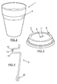
- FIG. 1 the four elements forming the disposable cup object of the invention can be seen: a container 1, a lid 2, a spoon 3 and a sleeving 4.
- Figure 2 the container 1, having a shape 5 which allows a more comfortable and safer coupling to the user's hand, can be seen.
- Figure 3 shows the lid 2, having a round hole 6 in the center with a radial slit 7 having a flexible opening with a length and width suitable for introducing the spoon 3 in a clean and easy manner.
- the central hole 6 has a fixing shape that can perfectly adapt to the fixing shape for fixing the spoon, both parts fitting together by means of slight pressure until coupling them to the fixing device.
- the hole for drinking, a mouth piece or drinking area 8 is located at one of the ends of the lid, slightly raised and with a small hole for achieving a better adaptation to the user's mouth.
- the third element forming the invention is the spoon 3, which is represented in Figure 4 .
- It is a rod having at one of its ends a paddle-shaped flare 10 in which a series of small holes can be made so as to facilitate the flow of the liquid, and it has a series of bends near the other end which define a C-shaped layout, the central branch 11 of which passes through the hole 6 of the lid, the end part projecting, performing crank functions once the spoon has been coupled to the lid 2.
- This end of the spoon 3 has a flexible base so that the user can bend it to his or her liking.
- the spoon has a holding shape consisting of a rib 12 with an intermediate groove 13 that can be adjusted to the edge of the hole 6 of the lid 2.
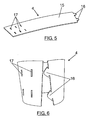
- Figures 5 and 6 show the sleeving 4, usually made of cardboard, which is wound around the container to prevent burning one's hands in the event that the content is hot.
- Said sleeving 4 consists of a laminar part 15 having a slightly trapezoidal contour which extends from one of its smaller side edges into arrowhead-shaped tabs 16 while near the other opposite smaller side it has transverse slits sized to receive the tabs 16.
- the tabs 16 will be introduced in determined slits depending on the size of the cup.
- the process of applying the invention is as follows: the sleeving 4 is coupled to the container 1 and the liquid is poured into the latter. Then the container 1 is closed with the lid 2 and the spoon 3 is introduced through the opening that the lid 2 has in the central part thereof and is coupled as a result of the holding shape that the hole 6 of the lid has and the holding shape that the spoon 3 has. The spoon 3 is fixed to the lid 2, allowing rotating the spoon 360° and thus stirring the liquid content.
Landscapes
- Engineering & Computer Science (AREA)
- Chemical & Material Sciences (AREA)
- Chemical Kinetics & Catalysis (AREA)
- Mechanical Engineering (AREA)
- Food Science & Technology (AREA)
- Table Devices Or Equipment (AREA)
- Closures For Containers (AREA)
- Details Of Rigid Or Semi-Rigid Containers (AREA)
- Packging For Living Organisms, Food Or Medicinal Products That Are Sensitive To Environmental Conditiond (AREA)
- Packages (AREA)
- Table Equipment (AREA)
Abstract
Description
- The present invention relates to a disposable cup for drinking beverages, such as coffee, which are served in different café, hotel and restaurant establishments and having on one side a drinking area for drinking the beverage and on the other side a hole for introducing a spoon and being able to thus stir the liquid.
- Disposable cups formed by four separate parts, the container, lid, spoon and sleeving for covering the container in the event that the beverage being provided is very hot, can be found today in a number of establishments in the café, hotel and restaurant industry, especially in those establishments serving take-away hot beverages, such as coffee for example. In said cups, only the container, the lid and the sleeving can be coupled to one another, the spoon being independent from the rest of the parts. This has a number of drawbacks, since once the liquid is served in the container and the lid is coupled, said lid must be lifted again in order to stir the content or pour any new substance into the container.
- The invention relates to a disposable cup with a rotating spoon according to
claim 1. Preferred embodiments of the method and of the system are defined in the dependent claims. - The disposable cup comprises a container, a spoon, a lid with a hole for the passage of the spoon and a sleeving, all of which can be coupled to one another and made of a preferably disposable material.
- The container has a shape which allows a more comfortable and safer coupling to the user's hand.
- The spoon consists of a rod having a paddle-shaped flare at one end and a series of bends at the other end which define a C-shaped layout, the central branch of which passes through the hole of the lid, the end part projecting with crank functions. A radial slit with a length and width equal to or greater than the section of the paddle starts from the hole of the lid.
- The spoon can have in the central branch of the C-shaped span a rib with an intermediate groove that can be adjusted to the edge of the hole.
- The lid can further have a mouth piece or drinking area next to its periphery.
- The sleeving consists of a laminar part having a slightly trapezoidal contour extending from one of its smaller sides into arrow head shaped tabs, while near the other opposite smaller side it has transverse slits sized to receive the tabs.
- The cup object of the invention provides a number of advantages in relation to existing cups. First, since the spoon is coupled to the fixing device of the lid, it can rotate 360° in both directions, completely stirring the liquid of the container. The shape of the cup further allows being held perfectly, more naturally and more safely in the user's hand. The sleeving can also be adapted to the size of the cup, according to whether it is small, medium or large sized, and advertising of the establishment or of associated companies can be added. Finally, the drinking area better adapts to the user's mouth since it has a "short straw" type shape, allowing pleasant and safe contact.
- To better understand the invention, an embodiment of the invention is very briefly described below as an illustrative and non-limiting example thereof. To that end, reference is made to the attached drawings in which:
-
Figure 1 shows the disposable cup object of the invention, with all its elements already assembled. -
Figure 2 shows the container of the cup. -
Figure 3 shows the lid of the cup. -
Figure 4 shows the spoon of the cup. -
Figure 5 shows the sleeving of the cup without winding. -
Figure 6 shows the sleeving of the cup in the winding process. - In view of
Figure 1 the four elements forming the disposable cup object of the invention can be seen: acontainer 1, alid 2, aspoon 3 and asleeving 4. - In
Figure 2 thecontainer 1, having ashape 5 which allows a more comfortable and safer coupling to the user's hand, can be seen. -
Figure 3 shows thelid 2, having around hole 6 in the center with aradial slit 7 having a flexible opening with a length and width suitable for introducing thespoon 3 in a clean and easy manner. Thecentral hole 6 has a fixing shape that can perfectly adapt to the fixing shape for fixing the spoon, both parts fitting together by means of slight pressure until coupling them to the fixing device. The hole for drinking, a mouth piece ordrinking area 8, is located at one of the ends of the lid, slightly raised and with a small hole for achieving a better adaptation to the user's mouth. - The third element forming the invention is the
spoon 3, which is represented inFigure 4 . It is a rod having at one of its ends a paddle-shaped flare 10 in which a series of small holes can be made so as to facilitate the flow of the liquid, and it has a series of bends near the other end which define a C-shaped layout, thecentral branch 11 of which passes through thehole 6 of the lid, the end part projecting, performing crank functions once the spoon has been coupled to thelid 2. This end of thespoon 3 has a flexible base so that the user can bend it to his or her liking. In saidcentral branch 11 the spoon has a holding shape consisting of arib 12 with anintermediate groove 13 that can be adjusted to the edge of thehole 6 of thelid 2. -
Figures 5 and 6 show thesleeving 4, usually made of cardboard, which is wound around the container to prevent burning one's hands in the event that the content is hot. Said sleeving 4 consists of alaminar part 15 having a slightly trapezoidal contour which extends from one of its smaller side edges into arrowhead-shaped tabs 16 while near the other opposite smaller side it has transverse slits sized to receive thetabs 16. Thetabs 16 will be introduced in determined slits depending on the size of the cup. - The process of applying the invention is as follows: the
sleeving 4 is coupled to thecontainer 1 and the liquid is poured into the latter. Then thecontainer 1 is closed with thelid 2 and thespoon 3 is introduced through the opening that thelid 2 has in the central part thereof and is coupled as a result of the holding shape that thehole 6 of the lid has and the holding shape that thespoon 3 has. Thespoon 3 is fixed to thelid 2, allowing rotating the spoon 360° and thus stirring the liquid content.
Claims (4)
- A disposable cup with a rotating spoon comprising a container, a spoon, a lid with a hole for the passage of the spoon and a sleeving which can be coupled to one another, characterized in that the spoon consists of a rod having a paddle-shaped flare at one end and a series of bends near the other end which define a C-shaped layout, the central branch of which passes through the hole of the lid, the end part projecting with crank functions, and in that a radial slit with a length and width equal to or greater than the section of the paddle starts from the hole of the lid.
- A disposable cup with a rotating spoon according to claim 1, characterized in that the spoon has in the central branch of the C-shaped span a rib with an intermediate groove that can be adjusted to the edge of the hole.
- A disposable cup with a rotating spoon according to any of the previous claims, characterized in that the lid further has a mouth piece or drinking area next to its periphery.
- A disposable cup with a rotating spoon according to any of the previous claims, characterized in that the sleeving consists of a laminar part having a slightly trapezoidal contour extending from one of its smaller sides into arrowhead-shaped tabs, while near the other opposite smaller side it has transverse slits sized to receive the tabs.
Applications Claiming Priority (2)
| Application Number | Priority Date | Filing Date | Title |
|---|---|---|---|
| ES200501836U ES1062009Y (en) | 2005-07-28 | 2005-07-28 | DISPOSABLE GLASS WITH ROTATING SPOON. |
| PCT/ES2006/000350 WO2007012679A1 (en) | 2005-07-28 | 2006-06-14 | Disposable cup comprising a rotary stirrer |
Publications (3)
| Publication Number | Publication Date |
|---|---|
| EP1908377A1 true EP1908377A1 (en) | 2008-04-09 |
| EP1908377A4 EP1908377A4 (en) | 2013-04-17 |
| EP1908377B1 EP1908377B1 (en) | 2015-02-25 |
Family
ID=36441124
Family Applications (1)
| Application Number | Title | Priority Date | Filing Date |
|---|---|---|---|
| EP06794025.4A Not-in-force EP1908377B1 (en) | 2005-07-28 | 2006-06-14 | Disposable cup comprising a rotary stirrer |
Country Status (11)
| Country | Link |
|---|---|
| US (1) | US8092072B2 (en) |
| EP (1) | EP1908377B1 (en) |
| JP (1) | JP2009502283A (en) |
| CN (1) | CN101227850A (en) |
| AU (1) | AU2006273986B2 (en) |
| BR (1) | BRPI0614446A2 (en) |
| CA (1) | CA2614407C (en) |
| ES (1) | ES1062009Y (en) |
| MX (1) | MX2008000876A (en) |
| RU (1) | RU2008103036A (en) |
| WO (1) | WO2007012679A1 (en) |
Cited By (1)
| Publication number | Priority date | Publication date | Assignee | Title |
|---|---|---|---|---|
| US20220281646A1 (en) * | 2021-03-02 | 2022-09-08 | Stallar Pierce Lufrano-Jardine | Reusable drinking cup lid stopper and method |
Families Citing this family (26)
| Publication number | Priority date | Publication date | Assignee | Title |
|---|---|---|---|---|
| ES1062009Y (en) * | 2005-07-28 | 2006-08-01 | Cruz Alejandro Parias | DISPOSABLE GLASS WITH ROTATING SPOON. |
| US7946752B2 (en) * | 2005-09-06 | 2011-05-24 | Sharron Swartz | Mug with stirring mechanism |
| DE102007040996B4 (en) * | 2007-08-29 | 2016-01-07 | TOSSY Coffee Cup Lid UG (haftungsbeschränkt ) & Co.KG | Lid, in particular with drinking cup |
| WO2009133211A1 (en) * | 2008-04-29 | 2009-11-05 | Spooncup, S.L. | Disposable cup with a small rotary spoon |
| US8172452B2 (en) * | 2008-09-17 | 2012-05-08 | Stacked, Llc | Lid with collapsible stirrer |
| BR112014010165A2 (en) * | 2011-10-27 | 2017-04-25 | Gary Moore | shake container with stirrer |
| US9643141B2 (en) | 2011-10-27 | 2017-05-09 | Trimr, Llc | Shakeable container with agitator |
| JP2013249118A (en) * | 2012-06-01 | 2013-12-12 | Dainippon Printing Co Ltd | Insulation cup |
| USD804247S1 (en) | 2012-10-26 | 2017-12-05 | Trimr, Llc | Agitator on straw or rod for a shakable container |
| JP5497928B1 (en) * | 2013-03-08 | 2014-05-21 | 博和 大西 | Axial joining device |
| CN103466184A (en) * | 2013-09-15 | 2013-12-25 | 苏州多贝机械科技有限公司 | Paint tank for emulsion paint |
| US9380899B2 (en) * | 2013-12-13 | 2016-07-05 | Bradley Taylor | Beverage lid system, beverage lid and associated methods |
| US9399538B2 (en) * | 2013-12-13 | 2016-07-26 | Bradley Taylor | Beverage lid system, beverage lid and associated methods |
| CN106103301A (en) * | 2015-03-23 | 2016-11-09 | 克里多埃克里奥有限公司 | Container cover, container comprising container cover and method for manufacturing container cover |
| CN106388509B (en) * | 2016-12-20 | 2017-11-07 | 苍南中学 | A kind of slidingtype jar |
| US10493414B2 (en) * | 2016-12-21 | 2019-12-03 | A Hakeem Ahmad | Beverage stirring assembly |
| US20200189831A1 (en) * | 2017-04-28 | 2020-06-18 | Warren THOMPSON | Adjustable insulator |
| NL2021239B1 (en) * | 2018-07-04 | 2020-01-15 | Eggciting Products B V | Microwave oven, as well as a method for stirring foodstuff contained in a vessel disposed in the cooking cavity of such a microwave oven and a stirrer for such a microwave oven |
| CN110250855B (en) * | 2019-04-25 | 2020-11-10 | 江苏那美实业有限公司 | Anti-scald water cup |
| JP7536853B2 (en) * | 2019-07-11 | 2024-08-20 | ソシエテ・デ・プロデュイ・ネスレ・エス・アー | Easy to use mass processing pitcher |
| US11878278B2 (en) * | 2019-12-23 | 2024-01-23 | Antwaine J. Debnam | Versatile beverage-temperature modulator and spill preventer |
| EP3904227B1 (en) * | 2020-04-30 | 2023-07-19 | James Cropper 3D Products Limited | Improved container packaging |
| JP7148164B2 (en) * | 2020-07-02 | 2022-10-05 | 真司 澤田 | Beverage container cover |
| US11641963B2 (en) * | 2021-02-11 | 2023-05-09 | Alexander Rollett | Beverage holder and method |
| US20220387944A1 (en) * | 2021-06-02 | 2022-12-08 | Lifetime Brands, Inc. | Peanut butter stirrer |
| JP2023058196A (en) * | 2021-10-13 | 2023-04-25 | 凸版印刷株式会社 | beverage container holder |
Family Cites Families (33)
| Publication number | Priority date | Publication date | Assignee | Title |
|---|---|---|---|---|
| US497045A (en) * | 1893-05-09 | Drug-mixer | ||
| US430783A (en) * | 1890-06-24 | Charles j | ||
| US420262A (en) * | 1890-01-28 | Mixer | ||
| US906934A (en) * | 1906-01-20 | 1908-12-15 | Homer W Rightmyer | Popper or roaster. |
| US876633A (en) * | 1906-09-28 | 1908-01-14 | William Gray | Mixing and kneading machine. |
| US912842A (en) * | 1908-03-11 | 1909-02-16 | Robert T Griffiths | Mixing and kneading machine. |
| US1296326A (en) * | 1916-09-08 | 1919-03-04 | Richard Scollon | Mixing device. |
| US1399296A (en) * | 1921-06-23 | 1921-12-06 | John M Feeney | Egg-beater |
| US1879731A (en) * | 1931-01-08 | 1932-09-27 | Jerry J Buckley | Condiment holder |
| US2485303A (en) * | 1946-07-13 | 1949-10-18 | Marcus Louise | Combined spoon and medicine bottle |
| US2719703A (en) * | 1952-12-24 | 1955-10-04 | Boakes Isabella | Automatic cooking and stirring device |
| US2736536A (en) * | 1953-04-02 | 1956-02-28 | Benjamin B Banowitz | Cooking vessel cover and agitator |
| US2814473A (en) * | 1955-05-25 | 1957-11-26 | Harold J Kroll | Fluid agitator |
| US2946299A (en) * | 1958-01-30 | 1960-07-26 | Ivy B Clifford | Dough mixer and kneader |
| US3295836A (en) * | 1964-10-16 | 1967-01-03 | Frank A Langella | Portable agitator |
| US3417972A (en) * | 1968-01-31 | 1968-12-24 | Hoover Co | Blender jar with stirrer and strainer |
| US3544080A (en) * | 1968-12-23 | 1970-12-01 | Julius L Lawrence | Agitator |
| US3704007A (en) * | 1970-07-29 | 1972-11-28 | Paul T Kroeger | Paint can agitator and pouring top |
| US3894723A (en) * | 1972-07-10 | 1975-07-15 | Murray A Sanders | Removable agitator |
| US4049243A (en) * | 1976-07-19 | 1977-09-20 | Hyman Kramer | Blending and kneading apparatus |
| US4197018A (en) * | 1979-01-08 | 1980-04-08 | Groen Division - Dover Corporation | Mixer |
| US4422770A (en) * | 1982-01-20 | 1983-12-27 | Geible Harry F | Paint stirrer |
| US4460279A (en) * | 1982-08-25 | 1984-07-17 | Krasney Robert L | Liquid pitcher with mixer |
| US4763567A (en) * | 1988-01-11 | 1988-08-16 | Northland Aluminum Products, Inc. | Stovetop corn popper |
| US5586676A (en) * | 1995-10-20 | 1996-12-24 | National Packaging Corporation | Beverage container cap with stirrer |
| GB9606288D0 (en) | 1996-03-26 | 1996-05-29 | Ivex Corp | Sleeve for beverage cups |
| US5857615A (en) * | 1997-01-13 | 1999-01-12 | New Dimensions Folding Carton, Inc. | Container holder |
| DE10011726A1 (en) | 1999-07-20 | 2001-02-01 | Rodojka Adler | Kitchen cooking pot with hand-cranked mixer incorporated in lid |
| JP4446523B2 (en) * | 1999-10-25 | 2010-04-07 | 東罐興業株式会社 | muddler |
| US6286754B1 (en) | 2001-03-14 | 2001-09-11 | International Paper Company | Paperboard cup holder |
| JP2004073345A (en) | 2002-08-13 | 2004-03-11 | Tomei Kagaku Kogyo Kk | Stirring rod |
| US6986438B2 (en) * | 2003-09-12 | 2006-01-17 | Bernard Leung | Insulating sleeve |
| ES1062009Y (en) * | 2005-07-28 | 2006-08-01 | Cruz Alejandro Parias | DISPOSABLE GLASS WITH ROTATING SPOON. |
-
2005
- 2005-07-28 ES ES200501836U patent/ES1062009Y/en not_active Expired - Fee Related
-
2006
- 2006-06-14 AU AU2006273986A patent/AU2006273986B2/en not_active Ceased
- 2006-06-14 US US11/997,093 patent/US8092072B2/en not_active Expired - Fee Related
- 2006-06-14 RU RU2008103036/12A patent/RU2008103036A/en not_active Application Discontinuation
- 2006-06-14 CA CA2614407A patent/CA2614407C/en not_active Expired - Fee Related
- 2006-06-14 CN CNA2006800269276A patent/CN101227850A/en active Pending
- 2006-06-14 EP EP06794025.4A patent/EP1908377B1/en not_active Not-in-force
- 2006-06-14 BR BRPI0614446-2A patent/BRPI0614446A2/en not_active IP Right Cessation
- 2006-06-14 WO PCT/ES2006/000350 patent/WO2007012679A1/en not_active Ceased
- 2006-06-14 MX MX2008000876A patent/MX2008000876A/en active IP Right Grant
- 2006-06-14 JP JP2008523387A patent/JP2009502283A/en not_active Withdrawn
Non-Patent Citations (2)
| Title |
|---|
| No further relevant documents disclosed * |
| See also references of WO2007012679A1 * |
Cited By (1)
| Publication number | Priority date | Publication date | Assignee | Title |
|---|---|---|---|---|
| US20220281646A1 (en) * | 2021-03-02 | 2022-09-08 | Stallar Pierce Lufrano-Jardine | Reusable drinking cup lid stopper and method |
Also Published As
| Publication number | Publication date |
|---|---|
| CA2614407A1 (en) | 2007-02-01 |
| ES1062009U (en) | 2006-05-16 |
| CA2614407C (en) | 2014-06-03 |
| ES1062009Y (en) | 2006-08-01 |
| US20090147615A1 (en) | 2009-06-11 |
| JP2009502283A (en) | 2009-01-29 |
| AU2006273986A1 (en) | 2007-02-01 |
| CN101227850A (en) | 2008-07-23 |
| WO2007012679A1 (en) | 2007-02-01 |
| EP1908377A4 (en) | 2013-04-17 |
| BRPI0614446A2 (en) | 2011-03-29 |
| RU2008103036A (en) | 2009-09-10 |
| EP1908377B1 (en) | 2015-02-25 |
| AU2006273986B2 (en) | 2010-12-02 |
| MX2008000876A (en) | 2008-03-26 |
| US8092072B2 (en) | 2012-01-10 |
Similar Documents
| Publication | Publication Date | Title |
|---|---|---|
| EP1908377B1 (en) | Disposable cup comprising a rotary stirrer | |
| AU2005327008B2 (en) | Lid for a drinks container for accommodating an infusion drink | |
| US7748557B2 (en) | Method and apparatus for enhancing the sensory experience of consuming a beverage | |
| US20170196236A1 (en) | Combined vessel lid and tea bag receptacle and method of using | |
| US3090542A (en) | Closure cap for waxed paper cup | |
| US4825551A (en) | Strainer ladle | |
| JPH0635125U (en) | Beverage can | |
| US20130272086A1 (en) | Beverage Container | |
| US20030002385A1 (en) | Convertible drink shaker and glass | |
| JP6376670B2 (en) | Aerator apparatus and method for aerating potable liquid | |
| US6926169B2 (en) | Device for the insertion of an anti-drip element into the mouth of a bottle | |
| JPH1035662A (en) | Easy-to-open deaerating hole in easy-to-open can lid | |
| EP2272403A1 (en) | Disposable cup with a small rotary spoon | |
| WO2015005874A1 (en) | Cap attachment for drinking from cans | |
| US9902557B2 (en) | Clasping device for infusion bags III | |
| US20090277341A1 (en) | Sweetener stick for stirring a beverage | |
| EP2489607A1 (en) | Beverage container with drinking straw | |
| US20200260889A1 (en) | Device for making tea with a teabag or tea infuser | |
| JPH04279116A (en) | Extracting flavor food bag such as tea bag, etc., and its pressing-squeezing rod | |
| CN223830765U (en) | Sharing kettle | |
| US20090162491A1 (en) | Brewing sachet | |
| KR20080033310A (en) | Disposable Cup with Swivel Spoon | |
| KR20170002826U (en) | A cup hold cum straw | |
| CN2257141Y (en) | plastic sanitary cup | |
| KR200296598Y1 (en) | Multi can |
Legal Events
| Date | Code | Title | Description |
|---|---|---|---|
| PUAI | Public reference made under article 153(3) epc to a published international application that has entered the european phase |
Free format text: ORIGINAL CODE: 0009012 |
|
| AK | Designated contracting states |
Kind code of ref document: A1 Designated state(s): AT BE BG CH CY CZ DE DK EE ES FI FR GB GR HU IE IS IT LI LT LU LV MC NL PL PT RO SE SI SK TR |
|
| 17P | Request for examination filed |
Effective date: 20071120 |
|
| DAX | Request for extension of the european patent (deleted) | ||
| A4 | Supplementary search report drawn up and despatched |
Effective date: 20130320 |
|
| RIC1 | Information provided on ipc code assigned before grant |
Ipc: B65D 51/32 20060101ALI20130314BHEP Ipc: A47G 19/22 20060101ALI20130314BHEP Ipc: A47J 43/10 20060101ALI20130314BHEP Ipc: A47G 23/00 20060101AFI20130314BHEP Ipc: A47G 21/04 20060101ALI20130314BHEP Ipc: B65D 81/38 20060101ALI20130314BHEP |
|
| RIC1 | Information provided on ipc code assigned before grant |
Ipc: A47G 21/04 20060101ALI20140220BHEP Ipc: B65D 81/38 20060101ALI20140220BHEP Ipc: A47G 23/00 20060101AFI20140220BHEP Ipc: A47G 19/22 20060101ALI20140220BHEP Ipc: A47J 43/10 20060101ALI20140220BHEP Ipc: B65D 51/32 20060101ALI20140220BHEP |
|
| RAP1 | Party data changed (applicant data changed or rights of an application transferred) |
Owner name: STIRCUP, INC. |
|
| RIN1 | Information on inventor provided before grant (corrected) |
Inventor name: STIRCUP, INC. |
|
| GRAP | Despatch of communication of intention to grant a patent |
Free format text: ORIGINAL CODE: EPIDOSNIGR1 |
|
| INTG | Intention to grant announced |
Effective date: 20140515 |
|
| RIN1 | Information on inventor provided before grant (corrected) |
Inventor name: PARIAS CRUZ, ALEJANDRO |
|
| GRAS | Grant fee paid |
Free format text: ORIGINAL CODE: EPIDOSNIGR3 |
|
| GRAA | (expected) grant |
Free format text: ORIGINAL CODE: 0009210 |
|
| RIN1 | Information on inventor provided before grant (corrected) |
Inventor name: PARIAS CRUZ, ALEJANDRO |
|
| AK | Designated contracting states |
Kind code of ref document: B1 Designated state(s): AT BE BG CH CY CZ DE DK EE ES FI FR GB GR HU IE IS IT LI LT LU LV MC NL PL PT RO SE SI SK TR |
|
| REG | Reference to a national code |
Ref country code: GB Ref legal event code: FG4D |
|
| REG | Reference to a national code |
Ref country code: CH Ref legal event code: EP |
|
| REG | Reference to a national code |
Ref country code: IE Ref legal event code: FG4D |
|
| REG | Reference to a national code |
Ref country code: DE Ref legal event code: R096 Ref document number: 602006044586 Country of ref document: DE Effective date: 20150409 |
|
| REG | Reference to a national code |
Ref country code: AT Ref legal event code: REF Ref document number: 711175 Country of ref document: AT Kind code of ref document: T Effective date: 20150415 |
|
| REG | Reference to a national code |
Ref country code: NL Ref legal event code: VDEP Effective date: 20150225 |
|
| REG | Reference to a national code |
Ref country code: AT Ref legal event code: MK05 Ref document number: 711175 Country of ref document: AT Kind code of ref document: T Effective date: 20150225 |
|
| REG | Reference to a national code |
Ref country code: LT Ref legal event code: MG4D |
|
| PG25 | Lapsed in a contracting state [announced via postgrant information from national office to epo] |
Ref country code: FI Free format text: LAPSE BECAUSE OF FAILURE TO SUBMIT A TRANSLATION OF THE DESCRIPTION OR TO PAY THE FEE WITHIN THE PRESCRIBED TIME-LIMIT Effective date: 20150225 Ref country code: LT Free format text: LAPSE BECAUSE OF FAILURE TO SUBMIT A TRANSLATION OF THE DESCRIPTION OR TO PAY THE FEE WITHIN THE PRESCRIBED TIME-LIMIT Effective date: 20150225 Ref country code: ES Free format text: LAPSE BECAUSE OF FAILURE TO SUBMIT A TRANSLATION OF THE DESCRIPTION OR TO PAY THE FEE WITHIN THE PRESCRIBED TIME-LIMIT Effective date: 20150225 Ref country code: SE Free format text: LAPSE BECAUSE OF FAILURE TO SUBMIT A TRANSLATION OF THE DESCRIPTION OR TO PAY THE FEE WITHIN THE PRESCRIBED TIME-LIMIT Effective date: 20150225 |
|
| PGFP | Annual fee paid to national office [announced via postgrant information from national office to epo] |
Ref country code: GB Payment date: 20150608 Year of fee payment: 10 |
|
| PG25 | Lapsed in a contracting state [announced via postgrant information from national office to epo] |
Ref country code: IS Free format text: LAPSE BECAUSE OF FAILURE TO SUBMIT A TRANSLATION OF THE DESCRIPTION OR TO PAY THE FEE WITHIN THE PRESCRIBED TIME-LIMIT Effective date: 20150625 Ref country code: GR Free format text: LAPSE BECAUSE OF FAILURE TO SUBMIT A TRANSLATION OF THE DESCRIPTION OR TO PAY THE FEE WITHIN THE PRESCRIBED TIME-LIMIT Effective date: 20150526 Ref country code: AT Free format text: LAPSE BECAUSE OF FAILURE TO SUBMIT A TRANSLATION OF THE DESCRIPTION OR TO PAY THE FEE WITHIN THE PRESCRIBED TIME-LIMIT Effective date: 20150225 Ref country code: LV Free format text: LAPSE BECAUSE OF FAILURE TO SUBMIT A TRANSLATION OF THE DESCRIPTION OR TO PAY THE FEE WITHIN THE PRESCRIBED TIME-LIMIT Effective date: 20150225 |
|
| PG25 | Lapsed in a contracting state [announced via postgrant information from national office to epo] |
Ref country code: NL Free format text: LAPSE BECAUSE OF FAILURE TO SUBMIT A TRANSLATION OF THE DESCRIPTION OR TO PAY THE FEE WITHIN THE PRESCRIBED TIME-LIMIT Effective date: 20150225 |
|
| PG25 | Lapsed in a contracting state [announced via postgrant information from national office to epo] |
Ref country code: CZ Free format text: LAPSE BECAUSE OF FAILURE TO SUBMIT A TRANSLATION OF THE DESCRIPTION OR TO PAY THE FEE WITHIN THE PRESCRIBED TIME-LIMIT Effective date: 20150225 Ref country code: SK Free format text: LAPSE BECAUSE OF FAILURE TO SUBMIT A TRANSLATION OF THE DESCRIPTION OR TO PAY THE FEE WITHIN THE PRESCRIBED TIME-LIMIT Effective date: 20150225 Ref country code: DK Free format text: LAPSE BECAUSE OF FAILURE TO SUBMIT A TRANSLATION OF THE DESCRIPTION OR TO PAY THE FEE WITHIN THE PRESCRIBED TIME-LIMIT Effective date: 20150225 Ref country code: EE Free format text: LAPSE BECAUSE OF FAILURE TO SUBMIT A TRANSLATION OF THE DESCRIPTION OR TO PAY THE FEE WITHIN THE PRESCRIBED TIME-LIMIT Effective date: 20150225 Ref country code: RO Free format text: LAPSE BECAUSE OF FAILURE TO SUBMIT A TRANSLATION OF THE DESCRIPTION OR TO PAY THE FEE WITHIN THE PRESCRIBED TIME-LIMIT Effective date: 20150225 |
|
| PGFP | Annual fee paid to national office [announced via postgrant information from national office to epo] |
Ref country code: DE Payment date: 20150710 Year of fee payment: 10 |
|
| REG | Reference to a national code |
Ref country code: DE Ref legal event code: R097 Ref document number: 602006044586 Country of ref document: DE |
|
| PG25 | Lapsed in a contracting state [announced via postgrant information from national office to epo] |
Ref country code: PL Free format text: LAPSE BECAUSE OF FAILURE TO SUBMIT A TRANSLATION OF THE DESCRIPTION OR TO PAY THE FEE WITHIN THE PRESCRIBED TIME-LIMIT Effective date: 20150225 |
|
| PG25 | Lapsed in a contracting state [announced via postgrant information from national office to epo] |
Ref country code: IT Free format text: LAPSE BECAUSE OF FAILURE TO SUBMIT A TRANSLATION OF THE DESCRIPTION OR TO PAY THE FEE WITHIN THE PRESCRIBED TIME-LIMIT Effective date: 20150225 |
|
| PLBE | No opposition filed within time limit |
Free format text: ORIGINAL CODE: 0009261 |
|
| STAA | Information on the status of an ep patent application or granted ep patent |
Free format text: STATUS: NO OPPOSITION FILED WITHIN TIME LIMIT |
|
| PG25 | Lapsed in a contracting state [announced via postgrant information from national office to epo] |
Ref country code: MC Free format text: LAPSE BECAUSE OF FAILURE TO SUBMIT A TRANSLATION OF THE DESCRIPTION OR TO PAY THE FEE WITHIN THE PRESCRIBED TIME-LIMIT Effective date: 20150225 |
|
| REG | Reference to a national code |
Ref country code: CH Ref legal event code: PL |
|
| 26N | No opposition filed |
Effective date: 20151126 |
|
| PG25 | Lapsed in a contracting state [announced via postgrant information from national office to epo] |
Ref country code: SI Free format text: LAPSE BECAUSE OF FAILURE TO SUBMIT A TRANSLATION OF THE DESCRIPTION OR TO PAY THE FEE WITHIN THE PRESCRIBED TIME-LIMIT Effective date: 20150225 Ref country code: LU Free format text: LAPSE BECAUSE OF FAILURE TO SUBMIT A TRANSLATION OF THE DESCRIPTION OR TO PAY THE FEE WITHIN THE PRESCRIBED TIME-LIMIT Effective date: 20150614 |
|
| REG | Reference to a national code |
Ref country code: IE Ref legal event code: MM4A |
|
| REG | Reference to a national code |
Ref country code: FR Ref legal event code: ST Effective date: 20160229 |
|
| PG25 | Lapsed in a contracting state [announced via postgrant information from national office to epo] |
Ref country code: IE Free format text: LAPSE BECAUSE OF NON-PAYMENT OF DUE FEES Effective date: 20150614 Ref country code: LI Free format text: LAPSE BECAUSE OF NON-PAYMENT OF DUE FEES Effective date: 20150630 Ref country code: CH Free format text: LAPSE BECAUSE OF NON-PAYMENT OF DUE FEES Effective date: 20150630 |
|
| PG25 | Lapsed in a contracting state [announced via postgrant information from national office to epo] |
Ref country code: FR Free format text: LAPSE BECAUSE OF NON-PAYMENT OF DUE FEES Effective date: 20150630 Ref country code: BE Free format text: LAPSE BECAUSE OF FAILURE TO SUBMIT A TRANSLATION OF THE DESCRIPTION OR TO PAY THE FEE WITHIN THE PRESCRIBED TIME-LIMIT Effective date: 20150225 |
|
| REG | Reference to a national code |
Ref country code: DE Ref legal event code: R119 Ref document number: 602006044586 Country of ref document: DE |
|
| GBPC | Gb: european patent ceased through non-payment of renewal fee |
Effective date: 20160614 |
|
| PG25 | Lapsed in a contracting state [announced via postgrant information from national office to epo] |
Ref country code: DE Free format text: LAPSE BECAUSE OF NON-PAYMENT OF DUE FEES Effective date: 20170103 |
|
| PG25 | Lapsed in a contracting state [announced via postgrant information from national office to epo] |
Ref country code: BG Free format text: LAPSE BECAUSE OF FAILURE TO SUBMIT A TRANSLATION OF THE DESCRIPTION OR TO PAY THE FEE WITHIN THE PRESCRIBED TIME-LIMIT Effective date: 20150225 Ref country code: HU Free format text: LAPSE BECAUSE OF FAILURE TO SUBMIT A TRANSLATION OF THE DESCRIPTION OR TO PAY THE FEE WITHIN THE PRESCRIBED TIME-LIMIT; INVALID AB INITIO Effective date: 20060614 Ref country code: GB Free format text: LAPSE BECAUSE OF NON-PAYMENT OF DUE FEES Effective date: 20160614 |
|
| PG25 | Lapsed in a contracting state [announced via postgrant information from national office to epo] |
Ref country code: CY Free format text: LAPSE BECAUSE OF FAILURE TO SUBMIT A TRANSLATION OF THE DESCRIPTION OR TO PAY THE FEE WITHIN THE PRESCRIBED TIME-LIMIT Effective date: 20150225 |
|
| PG25 | Lapsed in a contracting state [announced via postgrant information from national office to epo] |
Ref country code: PT Free format text: LAPSE BECAUSE OF FAILURE TO SUBMIT A TRANSLATION OF THE DESCRIPTION OR TO PAY THE FEE WITHIN THE PRESCRIBED TIME-LIMIT Effective date: 20150225 |
|
| PG25 | Lapsed in a contracting state [announced via postgrant information from national office to epo] |
Ref country code: TR Free format text: LAPSE BECAUSE OF NON-PAYMENT OF DUE FEES Effective date: 20160614 |