EP1908376A2 - Porte de vitrine réfrigérée et son procédé de fabrication - Google Patents
Porte de vitrine réfrigérée et son procédé de fabrication Download PDFInfo
- Publication number
- EP1908376A2 EP1908376A2 EP07116355A EP07116355A EP1908376A2 EP 1908376 A2 EP1908376 A2 EP 1908376A2 EP 07116355 A EP07116355 A EP 07116355A EP 07116355 A EP07116355 A EP 07116355A EP 1908376 A2 EP1908376 A2 EP 1908376A2
- Authority
- EP
- European Patent Office
- Prior art keywords
- frame
- guide member
- closure
- opening
- snap
- Prior art date
- Legal status (The legal status is an assumption and is not a legal conclusion. Google has not performed a legal analysis and makes no representation as to the accuracy of the status listed.)
- Withdrawn
Links
- 238000004519 manufacturing process Methods 0.000 title claims description 8
- 238000000034 method Methods 0.000 title claims description 5
- 239000011521 glass Substances 0.000 claims abstract description 56
- 238000002347 injection Methods 0.000 claims abstract description 21
- 239000007924 injection Substances 0.000 claims abstract description 21
- 229920001577 copolymer Polymers 0.000 claims abstract description 16
- 230000002093 peripheral effect Effects 0.000 claims description 136
- 238000007789 sealing Methods 0.000 claims description 17
- 239000000463 material Substances 0.000 claims description 12
- 239000004033 plastic Substances 0.000 claims description 2
- 238000007711 solidification Methods 0.000 claims 3
- 230000008023 solidification Effects 0.000 claims 3
- 239000000853 adhesive Substances 0.000 abstract description 24
- 230000001070 adhesive effect Effects 0.000 abstract description 24
- 239000011324 bead Substances 0.000 description 19
- 229910052751 metal Inorganic materials 0.000 description 7
- 239000002184 metal Substances 0.000 description 7
- 238000010276 construction Methods 0.000 description 5
- 210000001331 nose Anatomy 0.000 description 5
- 238000001125 extrusion Methods 0.000 description 3
- 230000004888 barrier function Effects 0.000 description 2
- 238000000576 coating method Methods 0.000 description 2
- 238000001816 cooling Methods 0.000 description 2
- 125000006850 spacer group Chemical group 0.000 description 2
- 239000005341 toughened glass Substances 0.000 description 2
- 229910052782 aluminium Inorganic materials 0.000 description 1
- XAGFODPZIPBFFR-UHFFFAOYSA-N aluminium Chemical compound [Al] XAGFODPZIPBFFR-UHFFFAOYSA-N 0.000 description 1
- 239000012080 ambient air Substances 0.000 description 1
- 230000015572 biosynthetic process Effects 0.000 description 1
- 239000011248 coating agent Substances 0.000 description 1
- 238000009833 condensation Methods 0.000 description 1
- 230000005494 condensation Effects 0.000 description 1
- 230000003247 decreasing effect Effects 0.000 description 1
- 238000001035 drying Methods 0.000 description 1
- 229940014425 exodus Drugs 0.000 description 1
- 239000003000 extruded plastic Substances 0.000 description 1
- 210000000887 face Anatomy 0.000 description 1
- 238000010438 heat treatment Methods 0.000 description 1
- 230000005923 long-lasting effect Effects 0.000 description 1
- 238000004806 packaging method and process Methods 0.000 description 1
- 230000003014 reinforcing effect Effects 0.000 description 1
- 230000000717 retained effect Effects 0.000 description 1
Images


Classifications
-
- A—HUMAN NECESSITIES
- A47—FURNITURE; DOMESTIC ARTICLES OR APPLIANCES; COFFEE MILLS; SPICE MILLS; SUCTION CLEANERS IN GENERAL
- A47F—SPECIAL FURNITURE, FITTINGS, OR ACCESSORIES FOR SHOPS, STOREHOUSES, BARS, RESTAURANTS OR THE LIKE; PAYING COUNTERS
- A47F3/00—Show cases or show cabinets
- A47F3/04—Show cases or show cabinets air-conditioned, refrigerated
-
- E—FIXED CONSTRUCTIONS
- E05—LOCKS; KEYS; WINDOW OR DOOR FITTINGS; SAFES
- E05D—HINGES OR SUSPENSION DEVICES FOR DOORS, WINDOWS OR WINGS
- E05D7/00—Hinges or pivots of special construction
- E05D7/10—Hinges or pivots of special construction to allow easy separation or connection of the parts at the hinge axis
- E05D7/1005—Hinges or pivots of special construction to allow easy separation or connection of the parts at the hinge axis by axially moving free pins, balls or sockets
- E05D7/1011—Hinges or pivots of special construction to allow easy separation or connection of the parts at the hinge axis by axially moving free pins, balls or sockets biased by free springs
-
- E—FIXED CONSTRUCTIONS
- E05—LOCKS; KEYS; WINDOW OR DOOR FITTINGS; SAFES
- E05F—DEVICES FOR MOVING WINGS INTO OPEN OR CLOSED POSITION; CHECKS FOR WINGS; WING FITTINGS NOT OTHERWISE PROVIDED FOR, CONCERNED WITH THE FUNCTIONING OF THE WING
- E05F3/00—Closers or openers with braking devices, e.g. checks; Construction of pneumatic or liquid braking devices
-
- F—MECHANICAL ENGINEERING; LIGHTING; HEATING; WEAPONS; BLASTING
- F25—REFRIGERATION OR COOLING; COMBINED HEATING AND REFRIGERATION SYSTEMS; HEAT PUMP SYSTEMS; MANUFACTURE OR STORAGE OF ICE; LIQUEFACTION SOLIDIFICATION OF GASES
- F25D—REFRIGERATORS; COLD ROOMS; ICE-BOXES; COOLING OR FREEZING APPARATUS NOT OTHERWISE PROVIDED FOR
- F25D23/00—General constructional features
- F25D23/02—Doors; Covers
-
- E—FIXED CONSTRUCTIONS
- E05—LOCKS; KEYS; WINDOW OR DOOR FITTINGS; SAFES
- E05Y—INDEXING SCHEME ASSOCIATED WITH SUBCLASSES E05D AND E05F, RELATING TO CONSTRUCTION ELEMENTS, ELECTRIC CONTROL, POWER SUPPLY, POWER SIGNAL OR TRANSMISSION, USER INTERFACES, MOUNTING OR COUPLING, DETAILS, ACCESSORIES, AUXILIARY OPERATIONS NOT OTHERWISE PROVIDED FOR, APPLICATION THEREOF
- E05Y2900/00—Application of doors, windows, wings or fittings thereof
- E05Y2900/20—Application of doors, windows, wings or fittings thereof for furniture, e.g. cabinets
- E05Y2900/202—Application of doors, windows, wings or fittings thereof for furniture, e.g. cabinets for display cabinets, e.g. for refrigerated cabinets
Definitions
- the invention is directed to product display cabinets or cases which are used in self-service markets, stores, and other establishments in which products are displayed, viewed, selected and purchased.
- Such display cabinets generally operate below external ambient temperature.
- Such display cabinets include one or more glass paneled doors through which products on shelves in an interior compartment of the display case can be viewed.
- the closures or doors for such display cabinets include an insulated glass unit or assembly comprised of a plurality of glass panes disposed in substantially parallel side-by-side spaced relationship to each other. Normally spacers maintain the glass panes separated from each other and a peripheral seal unites the assembly into a unitized glass unit.
- Door frames for such glass units have been conventionally formed in many different ways. In accordance with U.S. Patent No. 3,673,735 issued on July 4, 1972 to Winsler et al ., a door frame is made from a plurality of rectangularly related extrusions made from aluminum or some other suitable metal.
- door frames are undesirable for use in refrigerated display cases because of the high heat conductivity of metal. More recently metal frames remain utilized in association with display doors for refrigerated display cases, but thermal insulating barrier members formed of molded, expanded or extruded plastic material are placed against the insulated glass unit to increase efficiency because the barrier members have relatively low heat conductivity.
- Conventional doors for refrigerated display cabinets also generally carry upper and lower outwardly spring-biased pivot pins which enter pivot openings in the door frame of an associated display cabinet.
- Insulated doors are relatively heavy and aligning and inserting the pivot pins into the pivot openings can be difficult, particularly when the pivot pins are under relatively high biasing forces.
- the present invention is directed to a novel display cabinet and particularly to a closure or a door therefor which is defined by four major components, namely, an outer polygonal annular frame member, an insulated glass unit, an inner polygonal annular frame member and an inner polygonal peripheral seal.
- the outer polygonal annular frame member is a single substantially homogeneous polymeric/ copolymeric injection molded member, as is also the inner polygonal annular frame member.
- the latter construction of the inner and outer polygonal annular frame members reduce heat conductivity to an absolute minimum, thereby creating a display door which is highly efficient and relatively inexpensive to both manufacture and assemble, as will be more evident hereinafter.
- the one-piece injection molded polymeric/copolymeric outer frame or bezel is defined by radially inwardly directed inner and outer border portions or flanges and a peripheral wall therebetween with the inner and outer flanges setting-off respectively larger and smaller polygonal openings.
- the insulating glass unit is also polygonal and is of a peripheral size which can pass through the inner opening of the outer frame but cannot pass through the outer opening of the outer frame.
- a second bead of adhesive peripheral bonds an inner peripheral surface of the IG glass unit to an inner peripheral edge of the inner frame while an outermost edge portion of the inner frame is snap-secured to a flange of the outer frame to forcefully retain the components in assembled condition incident to the curing/sofidification of the two adhesive beads.
- the door frame of the display door is made from only two major pieces of material each injection molded from polymeric/copolymeric material possessing low heat conductivity and through the utilization of two peripheral adhesive beads and a highly forceful peripheral snap connection between the inner and outer frames, the IG unit is held rigid until the adhesive of the two beads cures/sets.
- the latter construction provides simplicity of assembly in a relatively short period of time absent extraneous components, such as separate fasteners, and utilizes a minimum of major components, namely, four components defined by the one piece injection molded outer frame, the one piece injection molded inner frame, the glass unit and the sealing member. Only two beads of adhesive applied during assembly retain the components securely bonded together to provide a relatively inexpensive and long-lasting insulated display door.
- the display door just described also includes a pair of conventional pivot pins in substantially axially aligned relationship biased outwardly at upper and lower corners of the display door which engage in a pivot pin guiding and locating member of the invention associated with an opening in upper and lower walls of the display cabinet door frame.
- Each opening in the door frame is of specific configuration to accurately positionally locate therein the guiding and locating member which includes guide means for guiding each pivot pin into a pivot opening of the guiding/locating member. Since each pivot pin and guiding or locating member can be only connected to the display door frame in one position, each display door can be easily and accurately assembled by guiding each pivot pin between guiding surfaces of the guiding or guide member into each associated guide member pivot pin opening to assure that each display door is properly pivotably mounted with respect to the display cabinet.
- FIGURE 1 is a front perspective view, and illustrates a display cabinet including a plurality of insulating glass doors, a door frame, one of several vertical mullions and an interior or interior chamber of the cabinet in which products are housed and displayed.
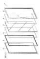
- FIGURE 2 is an exploded perspective view of the components used to manufacture each of the display doors of Figure 1, and illustrates from right-to-left a polygonal annular outer frame, a polygonal bead of adhesive, an insulating glass unit or assembly, another polygonal bead of adhesive, a polygonal annular inner frame, and a polygonal sealing member.
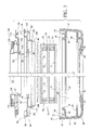
- FIGURE 3 is a fragmentary exploded cross-sectional view through the unassembled components of Figure 2, and more specifically illustrates the cross-sectional configurations thereof and the relationships of the components to each other.
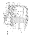
- FIGURE 4 is an enlarged cross-sectional view taken through any one of the display doors of Figure 1 and the display components of Figure 3 when fully assembled, and illustrates the components in assembled relationship.
- FIGURE 5 is a fragmentary perspective view of a corner of one of the display doors, and illustrates a pivot pin projecting upwardly therefrom.
- FIGURE 6 is a fragmentary perspective view of the upper right-hand corner of the display cabinet frame of Figure 1, and illustrates a pivot pin guiding and locating member snap-secured in an opening formed in a wall of the frame member.
- FIGURE 7 is a fragmentary front elevational view of the upper right-hand corner of the display cabinet of Figure 1, and illustrates the pivot pin of the display door located in a pivot pin opening of the pivot pin guiding member.
- FIGURE 8 is an enlarged cross-sectional view taken generally along line 8-8 of Figure 7, and illustrates the manner in which a conventional spring biases the pivot pin into the pivot pin opening of the pivot pin guiding member.
- FIGURE 9 is a top perspective view of the pivot pin guide or guiding member, and illustrates a guide path defined by inwardly converging opposing side guide surfaces for directing a pivot pin into the pivot pin opening of the guide member.
- FIGURE 10 is a bottom perspective view of the guide member of Figure 9, and illustrates oppositely projecting resilient fastening lugs and a locating slot in a forward peripheral face of a body of the guide member.
- FIGURE 11 is a top perspective view of another guide member, and illustrates an inwardly and upwardly tapering lower guide surface between inwardly converging opposing side guide surfaces.
- FIGURE 12 is fragmentary top plan view looking upwardly in Figure 6, and illustrates a positional locating opening in an upper horizontal frame member defined in part by an inwardly projecting locating tab which registers with a positional locating slot of the guide member.
- a novel refrigerated display cabinet, case, walk-in or the like is fully illustrated in Figure 1 of the drawings, and is generally designated by the reference numeral 10.
- the display cabinet 10 may be, for example, a self-contained refrigerated unit which, after manufacture, is shipped to a self-service store, market or like establishment in which perishable food items are stored on shelves (not shown) or the display cabinet 10 can be a so-called built-in by which the cabinet 10 can be framed-out at the use site.
- the display cabinet 10 includes a top wall 11 ( Figure 1), opposite substantially parallel side walls 12, of which only one is shown, and a bottom wall and a rear wall (not shown) collectively defining an interior product compartment or chamber 15 which is maintained below outside ambient temperature by a conventional cooling system (not shown).
- a front of the display cabinet 10 includes a door frame and door assembly 20 which is generally of a polygonal configuration, as viewed from the front, and defines an opening (unnumbered) which is subdivided into a plurality of individual openings O by a plurality of substantially horizontally spaced vertical mullions 27.
- a door frame 30 of the door frame and door assembly 20 has pivotally mounted therein a plurality of IG glass panel doors 21-25, each identically constructed in accordance with the present invention and each including upper and lower vertical pivot pins 26 (Figure 5) for pivoting each door 21-25 to respective upper and lower horizontal extruded metal frame members 31, 32 ( Figures 1 and 6-8) of the frame 30 which also includes vertical extruded metal end frame members 33 and three additional substantially identical vertical mullions (not shown) corresponding to the mullion 27 illustrated in Figure 1 of the drawings.
- Inboardmost walls (unnumbered) of the frame members/mullions 31-34 and 27 set-off five access openings O, one opening O associated with each door 21-25, through which products in the compartment 15 can be viewed and accessed.
- the display door 25 ( Figures 2, 3 and 4 of the drawings) includes an outer polygonal annular frame 40, a polygonal bead of bonding or adhesive material 60, an IG (insulating glass) unit or assembly 70, another polygonal bead of bonding material or adhesive 80, an inner annular polygonal frame 90 and an inner polygonal sealing member 120.
- the outer polygonal annular frame 40 including a handle H thereof ( Figures 1 and 2), is formed as a single substantially homogenous injection molded polymeric/copolymeric member which has heretofore been unprovided in refrigerated display cabinet IG doors.
- the inner annular polygonal frame 90 is also formed as a single substantially homogeneous polymeric/copolymeric injection molded member.
- the display door 25 is essentially of a three-piece construction, namely, both frames 40, 90 and the IG unit 70 imaginatively rigidly bonded together by the strategic location of the peripheral beads of adhesive material 60, 80, as will be described more specifically hereinafter.
- the outer polygonal frame 40 ( Figures 3 and 4) of the display door 25 includes a peripheral wall 41 and an outermost or outer border portion or flange 42 directed inwardly and defining an outer polygonal opening Oo of a polygonal configuration.
- the outer frame 40 further includes an inner or innermost border portion or flange 43 projecting inwardly from the peripheral wall 41 and defining a polygonal inner opening Oi which is appreciably smaller in size than the outer polygonal opening Oo defined by the flange 42.
- the peripheral wall 41 and the inwardly directed border portions or flanges 42, 43 define an inwardly opening peripherally extending chamber 45 into which interiorly projects a peripherally extending reinforcing rib 46.
- a peripheral terminal end wall portion 47 of the peripheral wall 41 terminates in a peripheral terminal end face or surface 48 and defines with a substantially parallel peripheral wall 50 a continuous inwardly opening peripheral groove 51.
- the peripheral wall 43 also includes a terminal peripheral end wall portion 52 and outboard thereof a peripherally extending locking face or surface 53 in part defining cooperative snap-securing means 55 ( Figure 4) which is associated with the inner polygonal annular frame 90 in a manner to be described more fully hereinafter.
- the adhesive bead 60 ( Figures 2, 3 and 4) is applied to an inner surface (unnumbered) of the flange 42 or to the IG unit or assembly 70 in the manner evident from Figure 3 of the drawings.
- the adhesive of the adhesive bead 60 is quick setting, curing or drying (within one hour) which is highly desirable for purposes of assembly, as will be described more fully hereinafter.
- the insulating glass unit or assembly 70 is also of a conventional construction and can include two, three or more pieces of tempered glass, such as tempered pieces of glass 71, 72 and 73 disposed in substantially spaced parallel relationship and retained thereat conventionally by spacers 74, 75 appropriately bonded and sealed to the glass pieces 71, 72; 72, 73 to produce an air-tight IG unit or assembly 70 which may include conventional infrared reflecting visible light transmitting coatings on one or more surfaces thereof, such as disclosed in U.S. Patent No. 4,382,177 granted to James J. Heaney on May 3, 1983 and reissued under RE 35,120 on December 12, 1995.
- One or more of the inner surfaces (unnumbered) of the tempered glass pieces 71, 72 and/or 73 may include a metallic strip electrode electrically conductively bonded to an electric conductive coating on a surface of one of the glass pieces 71-73 to reduce/eliminate condensation and/or include a heating element associated with the outer frame 40 in the manner disclosed in U.S. Patent No. 4,127,765 granted to James J. Heaney on November 28, 1978.
- the insulating glass unit 70 includes an exterior peripheral polygonal surface 76 which corresponds in shape to the shapes of the openings Oo and Oi, but the peripheral dimensions in both length and width of the peripheral surface 76 are greater than like dimensions of the opening Oo of the flange 42 of the outer frame 40, but less than the dimensions of the opening Oi of the flange 43 of the outer frame 40.
- the function of the latter dimensioning is disclosed in the commonly assigned patent of Herrmann et al. granted on April 20, 2004 under U.S. Patent No. 6,722,083 B2 .
- the dimensioning of the peripheral surface 76 of the insulating glass unit 70 permits the insulating glass unit 70 to be introduced downwardly as viewed in Figure 3 through the opening Oi of the peripheral flange 43 into the chamber 45 of the outer frame 40 to the position shown in Figure 4 with the adhesive bead 60 bonding an inner surface (unnumbered) of the outer flange or border 42 to an outer surface (unnumbered) of the outer glass piece 71 during assembly of the display door 25, as will be described more fully hereinafter.
- the adhesive bead 80 bonds an inner surface (unnumbered) of the inner polygonal annular frame 90 to an outer surface (unnumbered) of the piece of glass 73.
- the inner frame 90 includes a first innermost polygonal peripheral portion 91, an intermediate peripheral wall portion 92 and an outermost peripheral portion 93 which terminates in an outwardly directed peripheral terminal wall portion 94 having a face or surface 95 in intimate bearing peripheral sealing relationship to the end face 48 of the terminal end wall portion 47 of the outer frame 40.
- the innermost peripheral wall portion 91 includes two inwardly directed relatively spaced peripheral leg portions 96, 97 defining therebetween an inwardly diverging peripheral groove 98.
- the peripheral leg portion 96 intimately sealingly engages an outer surface (unnumbered) of the glass piece 73 of the IG unit 70 to preclude exodus of the adhesive or bonding material of the adhesive bead 80 the left, as viewed in Figure 4, and essentially retains the adhesive 80 positioned as shown in Figure 4.
- the outermost peripheral wall portion 93 of the inner frame 90 includes two outwardly directed peripheral wall portions or flanges 100, 101, the latter of which seats in the inwardly directed peripheral groove 51 of the outer frame 40 and snugly engages in surface-to-surface contact with the peripheral wall 50 of the flange 43 along two surfaces (unnumbered) thereof, as is readily apparent in Figure 4.
- the peripheral flange 100 is stepped and includes an innermost wall portion 102, an inclined medial wall portion 103 and an outermost wall portion 104.
- the wall portions 104, 103 include respective outermost peripherally extending surfaces 105, 106 which collectively define a peripheral guide surface for introducing the peripheral flange 100 progressively into and through the opening Oi of the peripheral flange 43 of the outer frame 40 until the peripheral flange 100 reaches its fully assembled and seated position, as shown in Figure 4.
- the guide surface 105 of the peripheral end portion 104 of the peripheral flange 100 is of a smaller peripheral dimension than the dimension of the opening Oi while the peripheral guide surface 106 progressively increases in peripheral size until reaching a snap-locking peripheral nose 110 forming the second part of the snap-securing means 55 which eventually intimately engages the locking face or surface 53 of the peripheral flange 43 of the outer frame 40 under sufficient force to draw the flange or border 42 of the outer frame 40 and the inner frame 90 toward each other under the appreciably high resilient force of the plastic material of the outer and inner frames 40, 90, respectively, in particular the force created between the respective peripheral wall portions 43, 102 thereof.
- This peripheral force particularly draws the flange 42 of the outer frame 40 and the innermost peripheral wall portion 91 of the inner frame 90 into intimate forceful contact with the outer surfaces (unnumbered) of the respective glass pieces 71, 73 squeezing the adhesive beads 60, 80, respectively, into intimate contact with all opposing peripheral surfaces to create a very strong bond once the adhesive of the adhesive beads 60, 80 has cured or set.
- the snap-securing means 50 thereby automatically creates a very strong or forceful clamping force which holds the components 40, 70, 90 assembled absent the use of conventional clamps, vises or the like, and when fully assembled by applying the inner polygonal sealing member 120 thereto, very quickly and easily, the display door 25 can be shipped very shortly after the adhesive beads 60, 80 have been applied and well before curing thereof which allows packaging and shipping to continue quickly and inexpensively.
- peripheral areas of contact between the outer and inner frames 40, 90 and the glass unit 70 namely, at the surfaces 48, 95; the two surface contacts between the peripheral walls 50, 101; the two peripheral surface contacts between the terminal peripheral wall portion 52 of the flange 43 and each of the adjacent peripheral surfaces of the flange portion 102 and the intermediate peripheral wall portion 92 of the inner frame, and the surface contact between the leg 96 and the outer surface of the piece of glass 73.
- the latter six peripheral surfaces of contact render the entire door extremely robust and rigidly united, including the formation of a very tight seal between the peripheral surfaces or faces 48, 95 ( Figure 4) to substantially seal the chamber 45 to atmosphere and reduce ambient air entry into the chamber 45 to thereby increase cooling efficiency when associated with the display case 10.
- the outer peripheral wall portion 93 of the inner frame 90 includes two inwardly directed peripheral flanges 111, 112 terminating in opposing noses 113, 114 defining therebetween a peripheral slot 115 and a wider peripheral chamber 116 which function in a manner to be described more fully hereinafter with respect to the inner polygonal sealing member or sealing means 120.
- the inner polygonal sealing member or sealing means 120 includes an innermost or inner peripheral wall portion 121, a medial peripheral wall portion 122 and an outer or outermost peripheral wall portion 123.
- the inner peripheral wall portion 121 includes an outwardly directed peripheral nose 124 converging outwardly which is received in the groove 98 of the inner peripheral wall portion 91 of the inner frame 90 and also includes a peripheral sealing edge 125 which intimately engages the outer surface (unnumbered) of the glass piece 73 to provide aesthetic appearance thereat.
- the opposite outer peripheral wall portion 123 of the inner polygonal sealing member 120 includes a peripheral outwardly directed securing flange 126 of a generally T-shaped transverse cross-section, whose arms 127, 128 resilient lockingly engage against the undersides of the noses 113, 114, respectively, to hold the inner polygonal sealing member 120 intimately secured to the inner frame 90.
- the medial portion 122 of the inner polygonal sealing member 120 includes a hollow chamber 130 defined by resilient peripheral walls 131, 132 which merge and define another annular chamber 134 housing conventional magnetic means 135 which are substantially polygonal in cross-section and with a relatively flat peripheral wall portion 136 magnetically secure the doors 21-25 closed through magnetic attraction relative to the various metal frame members and mullions 27, 33 of the frame 30 ( Figure 1) in a conventional manner.
- the display door 25 and each of the remaining display doors 21-24 can either be left-hand or right-hand openings and, in each case, upper and lower corners (unnumbered) of the doors are provided with conventional pivot means 150 ( Figures 5-8) which can conventionally include a torsion rod or torque rod 151, the pivot pin 26, a spring 153 for at all times urging a square pin end portion 154 of the pivot pin 26 outwardly of the outer frame 40 through an opening 155 in the peripheral wall 41 ( Figure 8).
- pivot means or pivot assembly 150 thus far described is relatively conventional but, in keeping with this invention, there is associated with each pivot pin end portion 154 pivot pin guiding and locating means 160 snap-secured in an opening 161 ( Figure 12) in each of the upper and lower frame members 31, 32, respectively, for guidingly locating the pin end portion 154 into a polygonal or rectangular opening 162 of the guiding means 160 to ease the assembly of each display door 21-25 relative to the frame 30.
- the guide member 160 includes a top surface 170 (Figure 9), an opposite bottom surface 171 ( Figure 10), and outer peripheral surfaces 172, 173 which are stepped relative to each other with the surface 172 being larger than the surface 173 and thereby defining a peripheral flange 174.
- the flange 174 is interrupted by diametrically oppositely opening slots 175 and aligned therewith are oppositely directed resilient locking legs, lugs or noses 176.
- the smaller peripheral surface 173 is provided with a slot 177 which in part defines positional locating means to accurately locate each guide member 160 with its associated opening 161 ( Figure 12) by engaging and interlocking with a tab 178 of the associated frame 31 projecting into the opening 161.
- the configuration of the opening 161 ( Figure 12) including the tab 178 substantially mirrors the configuration of the peripheral surface 173 and the slot 177 which assures that each guide member 160 can be snapped into an associated opening 161 of the frame 30 only in one specific position.
- the specific position is such that a guide path 180 defined by converging guide surfaces 181, 182 converges in a direction toward the interior of the display cabinet 10 and/or the compartment 15 thereof.
- the locking lugs 176, 176 snap engage the frame 31 at opposite sides of the opening 161 to firmly secure the guiding means 160 in each associated opening 161 ( Figures 7 and 12).
- each guide member 160 is snap-secured into each of the openings 161 which are positioned in vertically aligned relationship in the respective horizontal frame members 31, 32. Because of the single positional location provided by the means 177, 178 ( Figure 12), each guide member 160 is positioned such that the guide path or guide surface 180 not only converges toward the interior of the display cabinet 10 but also converges toward and terminates at the polygonal opening 162. With the display door 25 substantially vertical, its lower pin end portion (not shown) can be readily guided along the guide path 180 into the polygonal hole 162.
- a wall 183 ( Figure 9) spanning the distance between the converging guide surfaces 181, 182 is very thin and presents little problem with respect to pushing the pin end portion 154 beyond the entrance edge (unnumbered) of the thin wall 183 toward the pivot pin opening 162.
- the thickness in the front portion of the thin wall or surface 183 is best illustrated in Figure 10 and, if desired, the portion thereof between the peripheral walls 172, 173 can be removed while retaining the guide surfaces 181, 182 in their entirety.
- the equivalent surface or wall 183' of another guide member 160' can be instead progressively tapered upwardly, as shown in Figure 11, from its outer edge (unnumbered) inwardly toward a pivot pin opening 162' to progressively compress the spring 153 upon the introduction of the pivot pin 154 along the guide path 180' which upon entering the opening 162' will do so more readily because of the increased force created by the spring 153.
Landscapes
- Engineering & Computer Science (AREA)
- Mechanical Engineering (AREA)
- Physics & Mathematics (AREA)
- Thermal Sciences (AREA)
- Chemical & Material Sciences (AREA)
- Combustion & Propulsion (AREA)
- General Engineering & Computer Science (AREA)
- Refrigerator Housings (AREA)
- Freezers Or Refrigerated Showcases (AREA)
- Injection Moulding Of Plastics Or The Like (AREA)
- Securing Of Glass Panes Or The Like (AREA)
Applications Claiming Priority (1)
| Application Number | Priority Date | Filing Date | Title |
|---|---|---|---|
| US11/525,856 US8776443B2 (en) | 2006-09-25 | 2006-09-25 | Refrigerated display case door |
Publications (2)
| Publication Number | Publication Date |
|---|---|
| EP1908376A2 true EP1908376A2 (fr) | 2008-04-09 |
| EP1908376A3 EP1908376A3 (fr) | 2011-04-20 |
Family
ID=39099857
Family Applications (1)
| Application Number | Title | Priority Date | Filing Date |
|---|---|---|---|
| EP07116355A Withdrawn EP1908376A3 (fr) | 2006-09-25 | 2007-09-13 | Porte de vitrine réfrigérée et son procédé de fabrication |
Country Status (6)
| Country | Link |
|---|---|
| US (1) | US8776443B2 (fr) |
| EP (1) | EP1908376A3 (fr) |
| JP (1) | JP4992056B2 (fr) |
| KR (1) | KR20080028288A (fr) |
| CA (1) | CA2603593C (fr) |
| MX (1) | MX2007011800A (fr) |
Cited By (2)
| Publication number | Priority date | Publication date | Assignee | Title |
|---|---|---|---|---|
| US9980581B2 (en) | 2012-09-24 | 2018-05-29 | Carrier Corporation | Refrigerated sales cabinet |
| EP3785574A1 (fr) | 2019-08-27 | 2021-03-03 | Orrell Limited | Armoire à marchandise réfrigérée |
Families Citing this family (31)
| Publication number | Priority date | Publication date | Assignee | Title |
|---|---|---|---|---|
| US8733024B2 (en) * | 2005-10-28 | 2014-05-27 | Jamison Door Company | Flexible door with rigid insulation |
| US20100107497A1 (en) * | 2008-11-05 | 2010-05-06 | Magna Mirrors Of America, Inc. | Full view storm door |
| EP2425190A4 (fr) * | 2009-04-30 | 2012-10-17 | Maslen Technology Australia Pty Ltd | Système de porte pour présentoirs frigorifiques |
| US8776439B2 (en) | 2010-06-09 | 2014-07-15 | Hill Phoenix, Inc. | Modular door system for refrigerated case |
| US8845045B2 (en) * | 2010-06-09 | 2014-09-30 | Hill Phoenix, Inc. | Door closing control and electrical connectivity system for refrigerated case |
| US9157675B2 (en) | 2010-06-09 | 2015-10-13 | Hill Phoenix, Inc. | Insulated case construction |
| DE202011106732U1 (de) * | 2011-10-13 | 2013-01-14 | Montanstahl Ag | Fenster- oder Türenelement |
| NL1039440C2 (nl) * | 2012-03-06 | 2013-09-09 | Polyplastic Groep B V | Koelinrichting en toegangsdeur. |
| US8869493B2 (en) * | 2012-03-14 | 2014-10-28 | Thermoseal Industries, L.L.C. | Door for a refrigerated cabinet |
| US20130249371A1 (en) * | 2012-03-23 | 2013-09-26 | Whirlpool Corporation | Hinge assemblies for a domestic refrigerator |
| US8998354B2 (en) * | 2012-04-26 | 2015-04-07 | Anthony, Inc. | Thermally efficient refrigerator door and frame |
| WO2015084792A1 (fr) * | 2013-12-05 | 2015-06-11 | The Coca-Cola Company | Systèmes et procédés pour ensemble porte de présentoir de marchandises réfrigéré |
| US9526353B2 (en) * | 2014-07-22 | 2016-12-27 | Richard Chubb | Door for a freezer cabinet |
| KR101646378B1 (ko) * | 2014-11-11 | 2016-08-05 | 동부대우전자 주식회사 | 냉장고 도어 프레임 및 그 제조방법 |
| US10370890B2 (en) * | 2015-03-03 | 2019-08-06 | Nissho Industrial Co., Ltd. | Door frame structure and method for mounting door frame structure |
| CN111426124A (zh) | 2015-06-11 | 2020-07-17 | Lg 电子株式会社 | 冰箱 |
| KR102562149B1 (ko) * | 2015-07-14 | 2023-08-01 | 엘지전자 주식회사 | 냉장고용 도어 및 냉장고 |
| US9962014B2 (en) * | 2016-04-01 | 2018-05-08 | Zero Zone, Inc. | Holder for a refrigerated case |
| US10295248B2 (en) | 2017-01-09 | 2019-05-21 | Electrolux Home Products, Inc. | Refrigerator with glass door |
| EP3378360B1 (fr) | 2017-03-24 | 2022-07-27 | LG Electronics Inc. | Réfrigérateur |
| US10365029B2 (en) | 2017-09-01 | 2019-07-30 | EDC Energy Door Company | Insulated frame section and refrigerator door system constructed from such sections |
| US10473382B2 (en) * | 2017-09-01 | 2019-11-12 | EDC Energy Door Company | Insulated door and refrigerator door system including the insulated door |
| TR201713310A2 (tr) * | 2017-09-11 | 2019-03-21 | Bsh Ev Aletleri San Ve Tic As | Hava yönlendi̇rme elemanina sahi̇p bi̇r soğutucu ci̇haz |
| KR102693079B1 (ko) * | 2018-09-05 | 2024-08-09 | 삼성전자주식회사 | 냉장고 |
| US11116333B2 (en) | 2019-05-07 | 2021-09-14 | Carrier Corporation | Refrigerated display cabinet including microchannel heat exchangers |
| US11559147B2 (en) | 2019-05-07 | 2023-01-24 | Carrier Corporation | Refrigerated display cabinet utilizing a radial cross flow fan |
| KR102045510B1 (ko) * | 2019-06-24 | 2019-11-15 | 박지용 | 과냉각 냉각고 |
| US11702881B2 (en) * | 2020-02-19 | 2023-07-18 | Norix Group, Inc. | Ligature safe door |
| US11035167B1 (en) | 2020-03-03 | 2021-06-15 | Quaker Window Products Co. | Thermally enhanced extrudate for windows and doors |
| US11946313B2 (en) | 2020-09-04 | 2024-04-02 | Quaker Window Products Co. | Fenestration unit including slidable glass panels |
| CN216245098U (zh) * | 2021-11-08 | 2022-04-08 | 中山市凯腾电器有限公司 | 一种无包边玻璃门体和酒柜 |
Citations (3)
| Publication number | Priority date | Publication date | Assignee | Title |
|---|---|---|---|---|
| US5035085A (en) * | 1989-01-27 | 1991-07-30 | Ardco, Inc. | Refrigerator door assembly with thermal insulated door mounting frame |
| US5228240A (en) * | 1992-01-28 | 1993-07-20 | 2420 Door Co. | Refrigerator door assembly and method |
| US7043886B1 (en) * | 2003-01-07 | 2006-05-16 | Thermoseal Glass Corp. | Refrigerator door assembly |
Family Cites Families (21)
| Publication number | Priority date | Publication date | Assignee | Title |
|---|---|---|---|---|
| US3499245A (en) | 1967-01-23 | 1970-03-10 | Ardco Inc | Glass panel refrigerator door and frame |
| US3634971A (en) * | 1969-12-01 | 1972-01-18 | Gen Motors Corp | All plastic refrigerator door with integral bump stop handle |
| US3673735A (en) | 1969-12-31 | 1972-07-04 | Ardco Inc | Glass panel refrigerator door |
| US4127765A (en) | 1978-02-17 | 1978-11-28 | Anthony's Manufacturing Company, Inc. | Anti-condensation system for refrigerator doors |
| US4382177A (en) | 1980-09-15 | 1983-05-03 | Heaney James J | Substantially transparent insulating anti-condensation structure |
| US4741127A (en) | 1986-12-22 | 1988-05-03 | Ardco Inc. | Refrigerator door with thermal insulated outer frame |
| US4891912A (en) | 1987-07-07 | 1990-01-09 | Ardco, Inc. | Refrigerator door assembly with multiple gasket sealing arrangement |
| US4831780A (en) | 1987-07-07 | 1989-05-23 | Ardco Inc. | Refrigerator door assembly with thermal break frame |
| US4852303A (en) | 1987-12-10 | 1989-08-01 | Ardco, Inc. | Refrigerator door frame with insulated mullion |
| US4948206A (en) | 1988-12-02 | 1990-08-14 | Ardco, Inc. | Refrigerator door assembly with decorative front trim panels |
| US5024023A (en) | 1989-12-11 | 1991-06-18 | Ardco, Inc. | Insulated refrigerator door assembly with substantially all glass front doors |
| US5255473A (en) * | 1989-12-11 | 1993-10-26 | Ardco, Inc. | Refrigerator door assembly with stylized substantially all glass front |
| US4998382A (en) | 1989-12-11 | 1991-03-12 | Ardco, Inc. | Insulated refrigerator door assembly with substantially all glass front doors |
| US5910083A (en) | 1990-09-20 | 1999-06-08 | New Anthony, Inc. | Integral spacer for door rail |
| US5894706A (en) * | 1996-08-13 | 1999-04-20 | Herbst; Walter B. | Molded window door and method |
| JP3750283B2 (ja) * | 1997-06-09 | 2006-03-01 | 旭硝子株式会社 | 複層ガラス構造、保冷用ショーケースおよびそのドア |
| US6367223B1 (en) * | 2000-06-09 | 2002-04-09 | Anthony, Inc. | Display case frame |
| US6722083B2 (en) | 2001-11-28 | 2004-04-20 | Gemtron Corporation | Structural unit, specifically a door including an injected molded frame |
| US6925767B2 (en) * | 2002-10-09 | 2005-08-09 | Odl, Incorporated | Screwless window frame assembly |
| US7334371B2 (en) * | 2003-04-04 | 2008-02-26 | E.I. Du Pont De Nemours And Company | Glass laminates having improved structural integrity against severe stresses for use in external pressure plate glazing applications |
| JP5027382B2 (ja) * | 2004-05-14 | 2012-09-19 | 旭硝子株式会社 | ガラス扉のサッシ構造及びこれを用いる冷凍/冷蔵ショーケース |
-
2006
- 2006-09-25 US US11/525,856 patent/US8776443B2/en not_active Expired - Fee Related
-
2007
- 2007-09-13 EP EP07116355A patent/EP1908376A3/fr not_active Withdrawn
- 2007-09-19 KR KR1020070095232A patent/KR20080028288A/ko not_active Ceased
- 2007-09-21 CA CA2603593A patent/CA2603593C/fr not_active Expired - Fee Related
- 2007-09-24 MX MX2007011800A patent/MX2007011800A/es active IP Right Grant
- 2007-09-25 JP JP2007247693A patent/JP4992056B2/ja not_active Expired - Fee Related
Patent Citations (3)
| Publication number | Priority date | Publication date | Assignee | Title |
|---|---|---|---|---|
| US5035085A (en) * | 1989-01-27 | 1991-07-30 | Ardco, Inc. | Refrigerator door assembly with thermal insulated door mounting frame |
| US5228240A (en) * | 1992-01-28 | 1993-07-20 | 2420 Door Co. | Refrigerator door assembly and method |
| US7043886B1 (en) * | 2003-01-07 | 2006-05-16 | Thermoseal Glass Corp. | Refrigerator door assembly |
Cited By (5)
| Publication number | Priority date | Publication date | Assignee | Title |
|---|---|---|---|---|
| US9980581B2 (en) | 2012-09-24 | 2018-05-29 | Carrier Corporation | Refrigerated sales cabinet |
| US10285512B2 (en) | 2012-09-24 | 2019-05-14 | Carrier Corporation | Refrigerated sales cabinet |
| EP3785574A1 (fr) | 2019-08-27 | 2021-03-03 | Orrell Limited | Armoire à marchandise réfrigérée |
| GB2586963A (en) * | 2019-08-27 | 2021-03-17 | Orrell Ltd | Refrigerated merchandising cabinet |
| US11779134B2 (en) | 2019-08-27 | 2023-10-10 | Orrell Limited | Door arrangement for refrigerated merchandising cabinet |
Also Published As
| Publication number | Publication date |
|---|---|
| JP4992056B2 (ja) | 2012-08-08 |
| US8776443B2 (en) | 2014-07-15 |
| EP1908376A3 (fr) | 2011-04-20 |
| CA2603593A1 (fr) | 2008-03-25 |
| JP2008080124A (ja) | 2008-04-10 |
| MX2007011800A (es) | 2009-02-03 |
| KR20080028288A (ko) | 2008-03-31 |
| CA2603593C (fr) | 2011-07-26 |
| US20080122324A1 (en) | 2008-05-29 |
Similar Documents
| Publication | Publication Date | Title |
|---|---|---|
| CA2603593C (fr) | Porte de presentoir frigorifique et methode de fabrication | |
| US4223482A (en) | Refrigerator door structure | |
| US6122869A (en) | Composite door and frame | |
| US5255473A (en) | Refrigerator door assembly with stylized substantially all glass front | |
| US5111618A (en) | Refrigerator door assembly with stylized substantially all glass front | |
| US4998382A (en) | Insulated refrigerator door assembly with substantially all glass front doors | |
| US5024023A (en) | Insulated refrigerator door assembly with substantially all glass front doors | |
| US5035085A (en) | Refrigerator door assembly with thermal insulated door mounting frame | |
| US10799038B2 (en) | Plastic panel door | |
| US9879900B1 (en) | Column cabinet construction and method for door construction | |
| US5048233A (en) | Refrigerator door and method of manufacturing same | |
| US9526353B2 (en) | Door for a freezer cabinet | |
| US4145844A (en) | Refrigerator door construction | |
| KR20080044229A (ko) | 구조적 유닛, 특히 사출성형된 프레임을 갖는 도어 | |
| CN102713123B (zh) | 隔热门以及组装隔热门的方法 | |
| US4248489A (en) | Refrigerator door structure | |
| US4588235A (en) | Refrigerator door structure | |
| EP0382963A3 (fr) | Dispositif de porte pour réfrigérateur | |
| US9554660B2 (en) | Reach-in door for refrigerated cabinets | |
| KR20010033593A (ko) | 냉각 저장고 | |
| US5876104A (en) | Breaker assembly for refrigerated cabinet | |
| US7895806B2 (en) | Interlocking wall sections for refrigerated enclosures | |
| JPH0532623Y2 (fr) | ||
| KR102158285B1 (ko) | 냉장/냉동창고의 슬라이딩 도어용 프레임 연결구 | |
| JP2025183077A (ja) | 平型ショーケース |
Legal Events
| Date | Code | Title | Description |
|---|---|---|---|
| PUAI | Public reference made under article 153(3) epc to a published international application that has entered the european phase |
Free format text: ORIGINAL CODE: 0009012 |
|
| AK | Designated contracting states |
Kind code of ref document: A2 Designated state(s): AT BE BG CH CY CZ DE DK EE ES FI FR GB GR HU IE IS IT LI LT LU LV MC MT NL PL PT RO SE SI SK TR |
|
| AX | Request for extension of the european patent |
Extension state: AL BA HR MK RS |
|
| PUAL | Search report despatched |
Free format text: ORIGINAL CODE: 0009013 |
|
| AK | Designated contracting states |
Kind code of ref document: A3 Designated state(s): AT BE BG CH CY CZ DE DK EE ES FI FR GB GR HU IE IS IT LI LT LU LV MC MT NL PL PT RO SE SI SK TR |
|
| AX | Request for extension of the european patent |
Extension state: AL BA HR MK RS |
|
| 17P | Request for examination filed |
Effective date: 20111020 |
|
| AKX | Designation fees paid |
Designated state(s): AT BE BG CH CY CZ DE DK EE ES FI FR GB GR HU IE IS IT LI LT LU LV MC MT NL PL PT RO SE SI SK TR |
|
| 17Q | First examination report despatched |
Effective date: 20120213 |
|
| STAA | Information on the status of an ep patent application or granted ep patent |
Free format text: STATUS: THE APPLICATION IS DEEMED TO BE WITHDRAWN |
|
| 18D | Application deemed to be withdrawn |
Effective date: 20160401 |