EP1908370B1 - Brosse à dents et procédé destiné à sa fabrication - Google Patents
Brosse à dents et procédé destiné à sa fabrication Download PDFInfo
- Publication number
- EP1908370B1 EP1908370B1 EP07025064.2A EP07025064A EP1908370B1 EP 1908370 B1 EP1908370 B1 EP 1908370B1 EP 07025064 A EP07025064 A EP 07025064A EP 1908370 B1 EP1908370 B1 EP 1908370B1
- Authority
- EP
- European Patent Office
- Prior art keywords
- soft
- brush body
- carrier element
- resilient
- head part
- Prior art date
- Legal status (The legal status is an assumption and is not a legal conclusion. Google has not performed a legal analysis and makes no representation as to the accuracy of the status listed.)
- Expired - Lifetime
Links
- 238000000034 method Methods 0.000 title claims abstract description 30
- 238000004519 manufacturing process Methods 0.000 title abstract description 21
- 238000004140 cleaning Methods 0.000 claims abstract description 134
- 239000000463 material Substances 0.000 claims abstract description 24
- 238000002347 injection Methods 0.000 claims abstract description 5
- 239000007924 injection Substances 0.000 claims abstract description 5
- 239000004033 plastic Substances 0.000 claims abstract description 4
- 229920003023 plastic Polymers 0.000 claims abstract description 4
- 238000001746 injection moulding Methods 0.000 claims description 12
- 238000003466 welding Methods 0.000 claims description 6
- 229920000728 polyester Polymers 0.000 claims description 4
- 229920002725 thermoplastic elastomer Polymers 0.000 claims description 4
- 230000002093 peripheral effect Effects 0.000 claims description 3
- 239000004743 Polypropylene Substances 0.000 claims description 2
- 239000004793 Polystyrene Substances 0.000 claims description 2
- 239000004676 acrylonitrile butadiene styrene Substances 0.000 claims description 2
- -1 polypropylene Polymers 0.000 claims description 2
- 229920001155 polypropylene Polymers 0.000 claims description 2
- SCUZVMOVTVSBLE-UHFFFAOYSA-N prop-2-enenitrile;styrene Chemical compound C=CC#N.C=CC1=CC=CC=C1 SCUZVMOVTVSBLE-UHFFFAOYSA-N 0.000 claims description 2
- 229920000638 styrene acrylonitrile Polymers 0.000 claims description 2
- 239000012858 resilient material Substances 0.000 claims 5
- XECAHXYUAAWDEL-UHFFFAOYSA-N acrylonitrile butadiene styrene Chemical compound C=CC=C.C=CC#N.C=CC1=CC=CC=C1 XECAHXYUAAWDEL-UHFFFAOYSA-N 0.000 claims 1
- 229920000122 acrylonitrile butadiene styrene Polymers 0.000 claims 1
- 238000005259 measurement Methods 0.000 claims 1
- 229920002223 polystyrene Polymers 0.000 claims 1
- 239000013013 elastic material Substances 0.000 abstract description 15
- 230000000295 complement effect Effects 0.000 abstract description 2
- 238000013461 design Methods 0.000 abstract description 2
- 230000002708 enhancing effect Effects 0.000 abstract 1
- 239000000155 melt Substances 0.000 abstract 1
- 238000012360 testing method Methods 0.000 description 11
- 238000007373 indentation Methods 0.000 description 10
- 230000033001 locomotion Effects 0.000 description 10
- 238000009826 distribution Methods 0.000 description 6
- 210000002105 tongue Anatomy 0.000 description 5
- 238000009732 tufting Methods 0.000 description 5
- 239000004952 Polyamide Substances 0.000 description 4
- 239000002131 composite material Substances 0.000 description 4
- 229920002647 polyamide Polymers 0.000 description 4
- 230000008901 benefit Effects 0.000 description 3
- 206010013710 Drug interaction Diseases 0.000 description 2
- 238000004026 adhesive bonding Methods 0.000 description 2
- 238000011161 development Methods 0.000 description 2
- 230000018109 developmental process Effects 0.000 description 2
- 238000006073 displacement reaction Methods 0.000 description 2
- 230000000694 effects Effects 0.000 description 2
- 238000005516 engineering process Methods 0.000 description 2
- 238000009434 installation Methods 0.000 description 2
- 230000003993 interaction Effects 0.000 description 2
- 238000012805 post-processing Methods 0.000 description 2
- 238000002360 preparation method Methods 0.000 description 2
- 238000010998 test method Methods 0.000 description 2
- 208000002064 Dental Plaque Diseases 0.000 description 1
- 208000027418 Wounds and injury Diseases 0.000 description 1
- 230000006978 adaptation Effects 0.000 description 1
- 238000005452 bending Methods 0.000 description 1
- 239000011248 coating agent Substances 0.000 description 1
- 238000000576 coating method Methods 0.000 description 1
- 150000001875 compounds Chemical class 0.000 description 1
- 230000008878 coupling Effects 0.000 description 1
- 238000010168 coupling process Methods 0.000 description 1
- 238000005859 coupling reaction Methods 0.000 description 1
- 230000006378 damage Effects 0.000 description 1
- 238000013016 damping Methods 0.000 description 1
- 230000001419 dependent effect Effects 0.000 description 1
- 239000000428 dust Substances 0.000 description 1
- 238000000227 grinding Methods 0.000 description 1
- 208000014674 injury Diseases 0.000 description 1
- 238000003780 insertion Methods 0.000 description 1
- 230000037431 insertion Effects 0.000 description 1
- 238000000465 moulding Methods 0.000 description 1
- 229920003052 natural elastomer Polymers 0.000 description 1
- 229920001194 natural rubber Polymers 0.000 description 1
- 230000003287 optical effect Effects 0.000 description 1
- 210000003254 palate Anatomy 0.000 description 1
- 238000005498 polishing Methods 0.000 description 1
- 238000012545 processing Methods 0.000 description 1
- 239000007921 spray Substances 0.000 description 1
- 238000005507 spraying Methods 0.000 description 1
- 229920003051 synthetic elastomer Polymers 0.000 description 1
- 239000005061 synthetic rubber Substances 0.000 description 1
Images


Classifications
-
- A—HUMAN NECESSITIES
- A61—MEDICAL OR VETERINARY SCIENCE; HYGIENE
- A61C—DENTISTRY; APPARATUS OR METHODS FOR ORAL OR DENTAL HYGIENE
- A61C17/00—Devices for cleaning, polishing, rinsing or drying teeth, teeth cavities or prostheses; Saliva removers; Dental appliances for receiving spittle
- A61C17/16—Power-driven cleaning or polishing devices
- A61C17/22—Power-driven cleaning or polishing devices with brushes, cushions, cups, or the like
- A61C17/222—Brush body details, e.g. the shape thereof or connection to handle
-
- A—HUMAN NECESSITIES
- A46—BRUSHWARE
- A46B—BRUSHES
- A46B15/00—Other brushes; Brushes with additional arrangements
-
- A—HUMAN NECESSITIES
- A46—BRUSHWARE
- A46B—BRUSHES
- A46B7/00—Bristle carriers arranged in the brush body
- A46B7/04—Bristle carriers arranged in the brush body interchangeably removable bristle carriers
-
- A—HUMAN NECESSITIES
- A46—BRUSHWARE
- A46B—BRUSHES
- A46B7/00—Bristle carriers arranged in the brush body
- A46B7/06—Bristle carriers arranged in the brush body movably during use, i.e. the normal brushing action causing movement
- A46B7/08—Bristle carriers arranged in the brush body movably during use, i.e. the normal brushing action causing movement as a rotating disc
-
- A—HUMAN NECESSITIES
- A46—BRUSHWARE
- A46B—BRUSHES
- A46B9/00—Arrangements of the bristles in the brush body
- A46B9/06—Arrangement of mixed bristles or tufts of bristles, e.g. wire, fibre, rubber
-
- A—HUMAN NECESSITIES
- A46—BRUSHWARE
- A46B—BRUSHES
- A46B2200/00—Brushes characterized by their functions, uses or applications
- A46B2200/10—For human or animal care
- A46B2200/1066—Toothbrush for cleaning the teeth or dentures
-
- B—PERFORMING OPERATIONS; TRANSPORTING
- B29—WORKING OF PLASTICS; WORKING OF SUBSTANCES IN A PLASTIC STATE IN GENERAL
- B29L—INDEXING SCHEME ASSOCIATED WITH SUBCLASS B29C, RELATING TO PARTICULAR ARTICLES
- B29L2031/00—Other particular articles
- B29L2031/42—Brushes
- B29L2031/425—Toothbrush
Definitions
- the invention relates to a method for producing a toothbrush according to the preamble of claim 1 and to a toothbrush according to claim 21 produced according to this method.
- Toothbrushes with a conventional bristle field consisting of bundles of bristle filaments, for example of polyamide (PA) or polyester (PBT), and additional soft-elastic cleaning elements are for example from WO-A-00/64307 and the WO-A-01/21036 known.
- the conventional bristles serve for the ordinary cleaning of the teeth, while the soft-elastic cleaning elements can perform different functions, such as massage of the palate, damping the cleaning movement, removal of dental plaque or polishing the tooth surface.
- the soft-elastic cleaning elements are rod-shaped, have approximately the same length as the conventional bristle bundles and are peripherally arranged on the head part of the toothbrush.
- the elastic cleaning elements are flat, eg wave-shaped, and arranged within the conventional bristle field.
- several of the soft elastic cleaning elements are connected to each other via a material bridge of the same material.
- the US-A-5,628,082 describes a method for producing a toothbrush with conventional bristles and additional soft-elastic cleaning elements.
- the cleaning elements are prepared after the bristles of the head part of the toothbrush with conventional bristles by molding over the head part.
- the disadvantage of this is that the bristle filaments must be made ready for use before the production of the soft elastic structure, for example by rounding the bristle bundles or producing a predetermined profiling. Subsequently, a renewed insertion into the injection mold for the production of soft elastic cleaning element is necessary. In this post-processing, the bristle bundles can be damaged or contaminated.
- the invention is therefore based on the object to provide a method for producing a toothbrush with conventional bristles and at least one soft-elastic cleaning element available, in which the post-processing of bristled toothbrush head can be avoided.
- toothbrush comprises both conventional manual toothbrushes and electric toothbrushing devices.
- the latter may be plug-on parts for electric tooth-cleaning appliances or one-piece electric toothbrushes.
- the soft-elastic cleaning element in a toothbrush of the type mentioned at the beginning, is directly connected to the brush body connected.
- the conventional bristles are mounted on a hard plastic support member which is manufactured separately and fitted with conventional bristles prior to being inextricably bonded to the head portion of the brush body.
- the soft-elastic cleaning element is preferably in spatial proximity to the carrier element with the conventional bristles.
- the distance between adjacent conventional bristles on the carrier element and the soft-elastic cleaning elements around brush body is preferably less than 5 mm.
- the connection between the carrier element and the head part of the brush body is accomplished via a receptacle.
- the receptacle may be a complementary counterpart to the carrier element or to a coupling element arranged thereon.
- a flat recess, a pin, a hole or a groove can serve as a receptacle.
- a recess which is adapted to the outer shape of the carrier element, is particularly suitable for the permanent connection between the carrier element and the brush body.
- the cleaning elements are preferably arranged on the head part in the edge region around the recess.
- the carrier element is manufactured and bristled separately from the remaining brush body on which the at least one soft-elastic cleaning element is arranged.
- the bristles are preferably applied thereto cut, rounded or otherwise made ready for use.
- AFT Anchor Free Tufting
- IMT In Mold Tufting
- the production of the brush body is carried out with at least one soft-elastic cleaning element and optionally further soft elastic elements.
- the at least one soft-elastic cleaning element and optionally further flexible elements are connected directly, ie not via an additional carrier element, to the brush body.
- the further soft-elastic elements can be used, for example, for the ergonomic adaptation of the handle to the palm or for the design of an elastic region between the head part and the neck part.
- the preparation of the brush body with one or more soft-elastic cleaning elements and optionally further flexible elements is carried out in two- or multi-component injection molding, wherein the various soft elastic elements in one step and spray connect with the hard component of the brush body.
- the soft-elastic cleaning elements can also be produced by means of their own injection points, in particular when the soft-elastic cleaning elements have a color or Shore A deviating from the other soft-elastic elements Hardness should have.
- Conventional bristles consist for example of polyamide (PA) or polyester (PBT) and have a diameter of 0.1 mm to 0.25 mm. For example, they are grouped in bundles of 10 to 100 individual filaments.
- the soft-elastic cleaning elements which consist for example of thermoplastic elastomer (TPE), have higher material thicknesses for reasons of stability.
- the smallest dimension of a cross section (for example to 90% of the height of the cleaning element) by such a cleaning element is preferably between 0.5 mm to 3 mm.
- the material for the soft-elastic cleaning elements and optionally further soft elastic elements is preferably supplied via a material distribution channel in the handle or in the neck part.
- the soft elastic material is thereby supplied to those points where the soft elastic cleaning elements and optionally further soft elastic elements are provided. These are formed in corresponding cavities of the injection molding tool.
- the soft-elastic material can for example be injected into a receptacle intended for receiving the carrier element from the mouth of the material distribution channel to the attachment points for the soft-elastic cleaning elements.
- the material distribution channel on the neck part preferably has a minimum cross section of at least 0.5 mm 2 .
- the soft elastic material is covered by the carrier element after its mounting on the head part of the brush body.
- the advantage of this Manufacturing method is that the back of the head part has no unwanted Anspritzhey or distribution channels.
- the individual components corresponding mold cavities during the two or multi-component injection molding of the brush body recesses are preferably used, which are located in that area on which the support plate is to be mounted. This can be advantageous both in the case of linear and rotational transport of the brush body within the injection molding tool.
- these recesses are filled in the hard component of the brush body with the last-injected material component.
- connection of the carrier element with the head part of the brush body takes place. It is possible, for example, a connection directly after the injection molding of the brush body, wherein the brush body held after the injection molding in alignment, and the support elements are fed and mounted by means of conveyors.
- the connection can be made insoluble by mechanical means.
- the connection can be made by jamming, snapping or riveting.
- the compound can be prepared chemically by gluing, thermally by welding, in particular ultrasonic welding, or other heat input. Manufacturing technology is preferred that the carrier element consists of the same material as the hard components of the brush body, since in this case, only a hard component held ready for the preparation of the brush and must not be paid attention to mutual material compatibility. This has advantages, especially in ultrasonic welding.
- the carrier element according to the AFT (Anchor Free Tufting) technology is bristled and finished before it is connected by means of ultrasonic welding with the provided with at least one flexible cleaning elements brush body.
- the materials used for the carrier element and the hard components of the brush body are in particular polypropylene, styrene-acrylonitrile, polyester, polystyrene (PS), acrylonitrile-butadiene-styrene (ABS) or Isoplast®.
- the soft elastic elements are made of a particular thermoplastic elastomer, e.g. made of natural or synthetic rubber.
- the Shore A hardness of the soft component is preferably less than 90 and more preferably less than 40. Depending on the nature of the hard component is preferably a compatible, to choose during the injection molding soft elastic material.
- the toothbrush is preferably exposed after installation of the carrier element to a test device installed in the mounting device.
- a pressure force is exerted on the carrier element by means of a pin or a similar element. If the connection between the carrier element and the brush body is insufficient, it will be disconnected in this step.
- the brush body may include areas of soft elastic material which transmit the compressive force applied thereto to the support member.
- the adhesion between the support element and Check brush body for example by pressure by fingers or by a simple auxiliary tool such as a ballpoint pen. So that the area of soft elastic material is not damaged when carrying out the test, its thinnest point preferably has a thickness of at least 0.5 mm.
- test methods described can also be applied to toothbrushes without soft-elastic elements. This is particularly advantageous in toothbrushes made by means of AFT, in order to check the connection between the carrier element and the brush body.
- the problems which arise in the production of toothbrushes with conventional bristles and soft-elastic cleaning elements when overmolding the head part after bristling is eliminated. If the soft-elastic cleaning element is already in the bristle field, while the conventional bristles are being processed, it can also be prevented, according to the above-described manufacturing method, that the soft-elastic cleaning elements are damaged during processing of the bristles or contaminated by grinding dust.
- Another advantage of the separate production of brush body with cleaning element and carrier element with conventional bristles is that forms of soft elastic cleaning elements can be realized to a large extent.
- molds which contact the conventional bristles in the final assembled state or which are displaced when the carrier element is inserted can be realized.
- the demolding of the soft elastic structure is unproblematic.
- At least one soft-elastic cleaning element can be arranged on the brush body in such a way that the soft elastic cleaning element is set in motion, in particular vibration, by the movement of the rotatably mounted carrier element relative to the brush body.
- This can be accomplished, for example, by virtue of the fact that the carrier element has at least one lateral indentation and the cleaning element is positioned in the region of the indentation.
- the cleaning element is thus caused by the movement of the carrier element relative to the brush body in vibration.
- the cleaning elements are designed bent so that they protrude with their adjoining the free end region in the bristle field formed by the bristles and are offset in this way upon movement of the bristles relative to the brush body in motion.
- the angle relative to the axis of rotation of the carrier element is preferably less than 20 °. So that the set in motion soft elastic cleaning elements are not excessively worn on the base, the maximum angle of rotation of the carrier element with respect to the soft elastic cleaning elements is preferably less than 75 °, more preferably less than 45 °.
- the frontal zone of soft elastic material, which feeds the cleaning elements preferably provided with a layer thickness of about 1 mm in order to develop a shock-absorbing effect and to reduce the risk of injury.
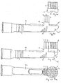
- all illustrated toothbrushes comprise a brush body 1 and a carrier element 2 equipped with conventional bristles 4.
- the brush body 1 comprises a head part 1a ', a neck part 1c and a subsequent thereto handle 1d, as he, for example, in Fig. 2a and 2c is indicated.
- the brush body 1 comprises a head portion 1 a 'and a neck portion 1 c.
- One-piece electric toothbrushes additionally comprise a handle which adjoins the neck portion.
- conventional bristles 4 and at least one soft-elastic cleaning element 3, which may have different shapes, are present on the head part 1a of the finished composite toothbrush.
- the conventional bristles 4 are mounted in bundles of bristles on a hard plastic carrier element 2, which is connected via a receptacle 5 with the brush body 1.
- a hard plastic carrier element 2 which is connected via a receptacle 5 with the brush body 1.
- Fig. 1a shows a front part of a brush body 1, which is shown for the sake of clarity without a soft elastic cleaning element, prior to assembly with a stocked already with bristles 4 Carrier element 2.
- carrier element 2 is equipped with conventional bristles 4, which are finished.
- AFT chor Free Tufting
- the support element 2 has the shape of a plate 2a with a protruding over a peripheral side wall 2b edge 2a 'and is adapted to the dimensions of a prepared area in the form of a flat recess 5' in the head part 1a 'of the brush body 1.
- the support member 2 is non-detachably connected to the brush body 1, for example by gluing or ultrasonic welding.
- Fig. 1c, d show a toothbrush according to the invention consisting of a brush body 1 with soft-elastic cleaning elements 3a, 3b and a stocked with conventional bristles 4 support element 2, the soft elastic cleaning elements 3a, 3b in the form of lamellae directly with the head part 1a of the brush body 1 according Fig. 1a are connected. These lamellar cleaning elements 3a, 3b are arranged in the lateral edge regions 1b around the recess 5 '.
- External cleaning elements 3a are arranged substantially parallel to the outer contour of the head part 1a and continue in a soft elastic covering 7a extending laterally on the neck part 1c towards the handle.
- An inner cleaning element 3b is aligned substantially parallel to the side wall 2b of the support element 2.
- the cleaning elements 3a, 3b are parallel to the direction of the bristles 4 from the head part 1a.
- the soft elastic cleaning elements 3 before inserting the bristled carrier element 2 in the Head part 1a of the brush body 1 to displace.
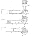
- Fig. 2a shows the front part of a brush body 1 a replaceable toothbrush.
- the soft-elastic cleaning elements 3 are arranged on the neck part 1c side facing the head part 1a 'of the brush body 1.
- the corresponding already equipped with bristles 4 support element 2, which represents the replaceable head, is in Fig. 2b displayed.
- the carrier element 2 can be inserted by means of a guide strip 6 in a longitudinal guide (not visible) at the front part of the brush body 1, which extends in the longitudinal direction of the brush body 1.
- the support member 2 is fixed by means of a releasable snap connection (not visible) against displacement in the longitudinal direction, such as in the WO-A-98/01055 disclosed.
- the soft-elastic cleaning elements 3 are rod-shaped on the neck part 1c facing side of the head part 1a of the brush body 1 is arranged.
- the neck portion 1c and the handle 1d are additionally profiled by a further soft elastic structure 7, which is preferably produced in the two-component or multi-component injection molding process in the same step as the soft-elastic cleaning elements 3 and connected to the hard component of the brush body 1.
- Fig. 2c shows the composite of brush body 1 and support element 2 replaceable head toothbrush in plan view. In the assembled state, the carrier element 2 equipped with conventional bristles 4 forms the front tip of the toothbrush according to the invention.
- Fig. 3a shows a already equipped with bristles 4 support element 2 in the form of a circular plate in front of the Mounting on the in Fig. 3b shown brush body 1 of a Aufsteckmaschines for an electric tooth cleaning device.
- Rod-shaped soft-elastic cleaning elements 3 are connected directly to the brush body 1 in the region of the free end of the head part 1a, as seen from Fig. 3b is apparent.
- the carrier element 2 is connected to the adapted thereto head part 1 a 'of the brush body 1 and a rotatably mounted about the axis A rotatably mounted turntable 5 "via a snap connection in a well-known manner for in Fig. 3c and 3d connected plug-on part.
- the carrier element 2 has, on the side facing away from the bristles 4, a groove 8 in which the counter element engages on the turntable 5 '' and which serves for rotational driving.
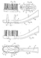
- the soft-elastic cleaning elements 3 are rod-shaped and arranged at a free end of the head part 1a located extension 12 of the brush body 1, which is located in the finished composite toothbrush at the height of the support element 2.
- the extension 12 is arcuate in plan view and adapted to the shape of the support element 2 so that it can rotate freely.
- the turntable 5 "and the carrier element 2 fastened thereto are moved back and forth during use via a generally known drive (not visible) .
- the bristles 4 and the cleaning elements 3 are aligned parallel to one another in the fully assembled state Cleaning elements 3 are substantially flush with the free end 4 'of the bristles 4.
- further soft elastic structures 7 on the neck part 1c and in the region between the neck part 1c and the head part 1a are formed, such as Fig. 3b, c demonstrate.
- Fig. 4a shows a to 3a analogue bristles 4 stocked Support element 2.
- the connection between the support element 2 and the turntable 5 "of in Fig. 4b shown Aufsteckteils is accomplished in an analogous manner, as is the case for the Fig. 3a, b has been described.
- Fig. 4c, d it can be seen, in this further embodiment of an inventive Aufsteckmaschines three lamellar soft-elastic cleaning elements 3, which are curved in the plan view of the circular support member coaxially, arranged one behind the other and mounted on the neck part 1c facing side of the head part 1a on a projection 13.
- soft elastic structures 7 are formed on the neck part 1b and in the area between the neck part 1c and the head part 1a, such as Fig. 4b, c demonstrate.
- the soft elastic cleaning elements 3 are fed in this embodiment via non-visible material channels in the interior of the Aufsteckteils, which can also be used for the production of other soft elastic structures.
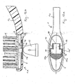
- Fig. 5a shows a substantially elliptical bristled carrier element 2 with four lateral indentations 9 in the side view.
- the connection between carrier element 2 and the in Fig. 5b The turntable 5 "of the brush body 1 is brought about by a generally known snap connection Fig. 5b shown brush body 1 around the turntable 5 "arranged.
- Fig. 5c, d show the fully assembled plug-on part for an electric tooth cleaning device in side view and top view.
- the four slightly inwardly bent and tapered toward the free ends 3 'towards rod-shaped cleaning elements 3 are on the head part 1 a of the brush body 1 laterally such arranged that they are arranged after the mounting of the support element 2 in the region of each one of the four indentations 9, as seen from Fig.
- the turntable 5 '' is offset by an invisible drive in an alternating rotational movement, which is transmitted to the carrier element 2. This puts the soft-elastic cleaning elements 3, which are arranged in the region of the indentations 9 laterally on the head part 1 a, by striking in vibration.
- the carrier plate is equipped in this embodiment with bristle bundles of various shapes and sizes. Several rectangular bundles directed against the center of rotation take over the cleaning of the tooth surface. A bundle arranged in the middle and projecting above the other bundles takes over the interdental cleaning.
- the cleaning elements 3 tapering towards the free ends 3 'are arranged laterally on the head part 1 a of the brush body 1 in such a way that, after assembly of the in Fig. 6c shown, already equipped with bristles 4 support element 2 on the in Fig.
- Fig. 7a shows a substantially circular conventional bristled carrier element 2.
- the connection between the carrier element 2 and the in Fig. 7b shown turntable 5 "of the brush body 1 is accomplished via a well-known snap connection Fig. 7c, d is the invention embarksteckteil after installation of in Fig. 7a, b shown components shown in side view and top view.
- the cleaning elements 3 taper towards the free end 3 'and are slightly bent inwards. They are connected to the head part 1 a of the brush body 1 in such a way that after the assembly of the in Fig. 7a represented, already equipped with bristles 4 carrier element 2 protrude into the bristle field formed by the bristles 4. In operation, the movement of the carrier element 2 is transmitted to the cleaning elements 3 via the peripheral bristles 4a.
- Fig. 8a, b is a stocked with bristles 4 carrier element 2 in side view and top view reproduced.
- the support member of this embodiment has bristle bundles of various shapes and sizes. The round bundles are used for surface cleaning and the elongated bundles of interdental cleaning.
- the oval support element 2 has lateral indentations 9 'for soft-elastic cleaning elements.
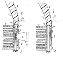
- Fig. 8c shows the front part of a finished brush body before mounting the in Fig. 8a, b shown carrier element, while in Fig. 8d the front part of a fully assembled inventive manual toothbrush is reproduced.
- the brush body 1 is produced with soft elastic cleaning elements 3 by a two- or multi-component injection molding.
- Fig. 8e It is about a in Fig. 8e indicated material distribution channel 10, which runs along the neck portion 1c, soft elastic material supplied.
- the soft elastic material 11 is guided in the receptacle 5 at the intended locations for the cleaning elements 3 and formed in corresponding cavities.
- the intended locations are arranged around the receptacle 5 in the edge region 1b.
- Fig. 8c, e show the brush body 1 after completed injection molding.
- Fig. 8c reproduced side view shows a introduced into the material distribution channel 10 soft elastic coating 7b on the neck portion 1c of the brush body 1.
- FIG. 8e shown exposed soft elastic material 11 in the head part 1 a 'of the brush body or at the bottom of the receptacle 5 is characterized by in Fig. 8a, b shown, already equipped with bristles 4 carrier element 2 after its mounting on the head part 1 a 'of the brush body 1 hidden.
- Fig. 9a shows the front part of a composite of brush body 1 and support member 2 toothbrush, for reasons of clarity, the soft elastic cleaning elements are not shown.
- the soft elastic material at the bottom of the receptacle 5 is penetrated by a breakthrough (not shown) at the end of the Neck parts 1c, which opens into the receptacle 5, fed.
- a breakthrough is made in advance in the hard component of the brush body 1 at the appropriate place.
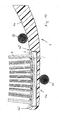
- the toothbrush according to the invention is exposed to a test device installed in the mounting device, as in Fig. 9b is indicated. In this case, a certain pressure force is exerted on the head part 1a protruding tongues 14 by means of pins 15.
- the tongues 14 are lateral extensions of the plate 2a of the support element 2.
- the compressive force is exerted on all three tongues 14 simultaneously, and this is reproduced for reasons of clarity only for the tongue at the front end of the toothbrush. Since a non-detachable connection between the carrier element 2 equipped with bristles 4 and the brush body 1 is desired, the assembly is considered successful if the carrier element 2 does not jump out of the receptacle 5 of the brush body 1.
- the tongues 14 are arranged laterally and at the top of the head part 1a, as seen from Fig. 9a is apparent. It is also possible that the support member projects beyond the receptacle in a different form and at a different location to allow a corresponding test during the manufacturing process or a corresponding test carried out by the consumer by hand.
- the test is carried out during the manufacturing process immediately after the mounting of the carrier plate and automatically linked to the assembly.
- test methods described above can be integrated as a process step in an AFT (Anchor Free Tufting) system. This toothbrushes are eliminated, which have insufficient adhesion between brush body and support element.
- AFT Anchor Free Tufting
Landscapes
- Health & Medical Sciences (AREA)
- Dentistry (AREA)
- Epidemiology (AREA)
- Life Sciences & Earth Sciences (AREA)
- Animal Behavior & Ethology (AREA)
- General Health & Medical Sciences (AREA)
- Public Health (AREA)
- Veterinary Medicine (AREA)
- Brushes (AREA)
Claims (21)
- Procédé de fabrication d'une brosse à dents comportant un corps de brosse (1) comprenant une partie de col (1c) et une partie de tête (1a, 1a') s'y raccordant ainsi que des soies conventionnelles (4) et au moins un élément de nettoyage élastique mou (3, 3a, 3b), comportant les étapes de procédé suivantes :a) fabriquer séparément un élément support (2) constitué d'un plastique dur,b) pourvoir l'élément support (2) de soies conventionnelles (4),c) fabriquer, grâce à un procédé de moulage par injection à deux composants ou plus, un corps de brosse (1) à partir d'un composant dur comprenant un logement (5) adapté à l'élément support (2) et au moins un élément de nettoyage (3, 3a, 3b) élastique mou disposé sur la partie de tête (1a, 1a'), relié directement au corps de brosse (1) et constitué d'un matériau élastique mou,d) relier à demeure l'élément support (2) pourvu des soies conventionnelles (4) au corps de brosse (1).
- Procédé selon la revendication 1, caractérisé en ce qu'avant la liaison de l'élément support (2) au corps de brosse (1), les soies (4) sont coupées et/ou arrondies et/ou préparées à l'utilisation d'une autre manière.
- Procédé selon la revendication 1 ou 2, caractérisé en ce que l'au moins un élément de nettoyage (3, 3a, 3b) élastique mou est déplacé avant l'insertion de l'élément support (2) garni de soies dans la partie de tête (1a) du corps de brosse (1).
- Procédé selon l'une quelconque des revendications 1 à 3, caractérisé en ce que les éléments de nettoyage (3, 3a, 3b) élastiques mous sont formés de telle sorte qu'ils soient en contact avec les soies conventionnelles (4) dans l'état monté final.
- Procédé selon l'une quelconque des revendications 1 à 4, caractérisé en ce que les éléments de nettoyage (3, 3a, 3b) élastiques mous sont formés de telle sorte qu'ils pénètrent dans un champ de soies formé par les soies conventionnelles (4).
- Procédé selon l'une quelconque des revendications 1 à 5, caractérisé en ce que l'au moins un élément de nettoyage (3a, 3b) est disposé dans la région de bord (1b) autour de l'évidement (5').
- Procédé selon l'une quelconque des revendications 1 à 6, caractérisé en ce que l'élément support (2) comprend au moins un renfoncement latéral (9) et l'élément de nettoyage (3) est disposé dans la région de ce renfoncement (9).
- Procédé selon l'une quelconque des revendications 1 à 7, caractérisé en ce qu'une distance de moins de 5 mm est réalisée entre l'au moins un élément de nettoyage (3, 3a, 3b) et les soies conventionnelles.
- Procédé selon l'une quelconque des revendications 1 à 8, caractérisé en ce que la liaison entre l'élément support (2) et la partie de tête (1a) est réalisée par soudage aux ultrasons ou par apport de chaleur.
- Procédé selon l'une quelconque des revendications 1 à 9, caractérisé en ce que le corps de brosse (1) est fabriqué avec au moins un canal de distribution de matériau (10), un matériau élastique mou (11) étant guidé à travers le canal de distribution de matériau (10) dans le logement (5) jusqu'à l'emplacement prévu pour l'élément de nettoyage (3) élastique mou.
- Procédé selon la revendication 10, caractérisé en ce que le matériau (11) élastique mou exposé dans la partie de tête (1a') du corps de brosse (1) ou au fond du logement (5) est recouvert par l'élément support (2) pourvu de soies conventionnelles (4) après son montage sur la partie de tête (1a') du corps de brosse (1).
- Procédé selon l'une quelconque des revendications 1 à 11, caractérisé en ce qu'après la liaison de l'élément support (2) au corps de brosse (1), la solidité de la liaison est contrôlée en exerçant une force de compression prédéfinie sur l'élément support (2) et/ou sur le corps de brosse (1).
- Procédé selon la revendication 12, caractérisé en ce que pour contrôler la solidité de la liaison entre l'élément support (2) et un corps de brosse (1), on effectue une mesure pour déterminer si l'élément support (2) se déplace par rapport au corps de brosse (1).
- Procédé selon l'une quelconque des revendications 1 à 13, caractérisé en ce que l'élément support (2) est fabriqué à partir du même matériau qu'un composant dur du corps de brosse (1).
- Procédé selon l'une quelconque des revendications 1 à 14, caractérisé en ce qu'on utilise, en tant que matériau pour l'élément support (2) et le corps de brosse (1), le polypropylène, le styrène-acrylonitrile, le polyester, le polystyrène, l'acrylonitrile-butadiène-styrène ou l'Isoplast.
- Procédé selon l'une quelconque des revendications 1 à 15, caractérisé en ce que l'élément de nettoyage (3, 3a, 3b) élastique mou est formé à partir d'un élastomère thermoplastique de dureté Shore A inférieure à 90, de préférence inférieure à 40.
- Procédé selon l'une quelconque des revendications 1 à 16, caractérisé en ce que le corps de brosse (1) comprend au moins un élément (7, 7a, 7b) élastique mou supplémentaire, et en ce que l'élément (7, 7a, 7b) élastique mou supplémentaire est fabriqué à partir du même matériau que celui de l'au moins un élément de nettoyage (3, 3a, 3b) élastique mou.
- Procédé selon la revendication 17, caractérisé en ce que l'au moins un élément de nettoyage (3, 3a, 3b) élastique mou et l'élément (7, 7a, 7b) élastique mou supplémentaire sont moulés par injection lors d'une étape et, à cet effet, un matériau élastique mou compatible avec le composant dur et s'y reliant pendant le processus de moulage par injection est sélectionné.
- Procédé selon la revendication 17 ou 18, caractérisé en ce que l'au moins un élément de nettoyage (3, 3a, 3b) élastique mou est fabriqué par le biais d'un point d'injection propre lorsque l'élément de nettoyage (3, 3a, 3b) élastique mou présente une couleur ou une dureté Shore A différant de celle de l'élément (7, 7a, 7b) élastique mou supplémentaire.
- Procédé selon l'une quelconque des revendications 1 à 19, caractérisé en ce qu'une partie de la partie de tête (1a) du corps de brosse (1) dans la région du logement (5) est fabriquée à partir d'un matériau élastique mou, lequel forme une zone (16) élastique molle.
- Brosse à dents fabriquée suivant un procédé selon l'une quelconque des revendications 1 à 20.
Applications Claiming Priority (2)
| Application Number | Priority Date | Filing Date | Title |
|---|---|---|---|
| DE10216641A DE10216641A1 (de) | 2002-04-15 | 2002-04-15 | Zahnbürste und Verfahren zu deren Herstellung |
| EP03707996A EP1494561B1 (fr) | 2002-04-15 | 2003-04-02 | Brosse a dents et procede de fabrication |
Related Parent Applications (1)
| Application Number | Title | Priority Date | Filing Date |
|---|---|---|---|
| EP03707996A Division EP1494561B1 (fr) | 2002-04-15 | 2003-04-02 | Brosse a dents et procede de fabrication |
Publications (2)
| Publication Number | Publication Date |
|---|---|
| EP1908370A1 EP1908370A1 (fr) | 2008-04-09 |
| EP1908370B1 true EP1908370B1 (fr) | 2014-06-25 |
Family
ID=28458838
Family Applications (3)
| Application Number | Title | Priority Date | Filing Date |
|---|---|---|---|
| EP07025064.2A Expired - Lifetime EP1908370B1 (fr) | 2002-04-15 | 2003-04-02 | Brosse à dents et procédé destiné à sa fabrication |
| EP07025063.4A Expired - Lifetime EP1908371B1 (fr) | 2002-04-15 | 2003-04-02 | Procédé de fabrication d'une brosse à dents |
| EP03707996A Expired - Lifetime EP1494561B1 (fr) | 2002-04-15 | 2003-04-02 | Brosse a dents et procede de fabrication |
Family Applications After (2)
| Application Number | Title | Priority Date | Filing Date |
|---|---|---|---|
| EP07025063.4A Expired - Lifetime EP1908371B1 (fr) | 2002-04-15 | 2003-04-02 | Procédé de fabrication d'une brosse à dents |
| EP03707996A Expired - Lifetime EP1494561B1 (fr) | 2002-04-15 | 2003-04-02 | Brosse a dents et procede de fabrication |
Country Status (5)
| Country | Link |
|---|---|
| EP (3) | EP1908370B1 (fr) |
| AT (1) | ATE383790T1 (fr) |
| AU (1) | AU2003212184A1 (fr) |
| DE (2) | DE10216641A1 (fr) |
| WO (1) | WO2003086140A1 (fr) |
Families Citing this family (16)
| Publication number | Priority date | Publication date | Assignee | Title |
|---|---|---|---|---|
| US6553604B1 (en) | 2000-03-16 | 2003-04-29 | Gillette Canada Company | Toothbrush |
| US8806695B2 (en) | 2002-08-09 | 2014-08-19 | Colgate-Palmolive Company | Oral care implement having flexibly supported cleaning elements extending in opposite directions |
| US7934284B2 (en) | 2003-02-11 | 2011-05-03 | Braun Gmbh | Toothbrushes |
| USD612611S1 (en) | 2003-02-11 | 2010-03-30 | The Gillette Company | Head of a toothbrush |
| US20040177462A1 (en) | 2003-03-14 | 2004-09-16 | The Gillette Company | Toothbrush head |
| US20060272112A9 (en) | 2003-03-14 | 2006-12-07 | The Gillette Company | Toothbrush |
| ES2650712T3 (es) | 2003-04-23 | 2018-01-22 | The Procter & Gamble Company | Cepillos dentales eléctricos |
| US7941886B2 (en) | 2003-09-19 | 2011-05-17 | Braun Gmbh | Toothbrushes |
| DE10353541B4 (de) * | 2003-11-14 | 2017-11-30 | Zahoransky Ag | Verfahren und Vorrichtung zur Herstellung von Bürsten mit Borstenbündeln und Noppen |
| DE102004057737B4 (de) * | 2004-08-18 | 2007-05-31 | Seçme, Münir | Zahnbürste |
| EP1661485A3 (fr) * | 2004-11-19 | 2012-07-11 | FIRMA G.B. BOUCHERIE, naamloze vennootschap | Brosse à dents |
| WO2006079122A1 (fr) * | 2005-01-21 | 2006-07-27 | Malcolm Duncan | Brosse a dent |
| US8429783B2 (en) | 2005-11-14 | 2013-04-30 | Colgate-Palmolive Company | Light-emitting oral care implement |
| DE102008057546B4 (de) | 2008-11-08 | 2020-01-16 | Zahoransky Ag | Bürstenherstellungsmaschine |
| EP2347673B1 (fr) | 2010-01-26 | 2015-08-05 | Trisa Holding AG | Procédé de fabrication d'une brosse à dents et brosse à dents |
| DE102019126766A1 (de) | 2019-10-04 | 2021-04-08 | Gb Boucherie Nv | Verfahren zum Überprüfen einer Stopfzunge eines Stopfwerkzeugs einer Bürstenherstellungsmaschine sowie Bürstenherstellungsmaschine |
Family Cites Families (21)
| Publication number | Priority date | Publication date | Assignee | Title |
|---|---|---|---|---|
| US1598224A (en) * | 1925-05-23 | 1926-08-31 | Robert H Van Sant | Toothbrush |
| US2614556A (en) * | 1951-11-29 | 1952-10-21 | Staunt Martin | Gum massager |
| US3553759A (en) * | 1968-09-24 | 1971-01-12 | Charles M Kramer | Toothbrush |
| US4543679A (en) * | 1982-10-08 | 1985-10-01 | Oral Ease Inc. | Toothbrush assembly combining a handle with a replaceable brush assembly and a replaceable oral hygiene device |
| DE3428860A1 (de) * | 1984-08-04 | 1986-02-13 | Horst 4800 Bielefeld Wiethölter | Zahnbuerste |
| DE3820372C2 (de) | 1988-06-15 | 1997-07-24 | Coronet Werke Gmbh | Verfahren und Vorrichtung zur Herstellung von Borstenwaren |
| EP0360766A1 (fr) * | 1988-09-19 | 1990-03-28 | Antonio Marino | Brosse à dents |
| US4972542A (en) * | 1989-02-13 | 1990-11-27 | Moshos Panagiotis N | Toothbrush apparatus |
| GB2250428B (en) * | 1990-12-03 | 1994-07-27 | Solar Wide Ind Ltd | Vibrating toothbrush |
| GB9423421D0 (en) * | 1994-11-19 | 1995-01-11 | Smithkline Beecham Plc | Novel device |
| US5628082A (en) | 1995-03-22 | 1997-05-13 | Colgate-Palmolive Company | Toothbrush with improved efficacy |
| GB9606900D0 (en) * | 1996-04-02 | 1996-06-05 | Unilever Plc | Toothbrush |
| DE59705675D1 (de) | 1996-07-08 | 2002-01-17 | Trisa Buerstenfabrik Ag | Zahnbürste sowie bürstenkopf für die zahnbürste |
| US5864915A (en) * | 1996-10-09 | 1999-02-02 | Ra; Dojin | Toothbrush |
| IT237420Y1 (it) * | 1997-04-11 | 2000-09-13 | Ponzini Spa | Spazzolino a testa intercambiabile migliorato |
| CH692098A5 (de) * | 1997-12-30 | 2002-02-15 | Trisa Buerstenfabrik Ag | Drehbeweglich antreibbarer Bürstenkopf für eine motorisch betriebene Zahnbürste, insbesondere eine Elektrozahnbürste. |
| KR20000047379A (ko) * | 1998-12-31 | 2000-07-25 | 박경식 | 칫솔 |
| EP1171014A1 (fr) | 1999-04-22 | 2002-01-16 | Kao Corporation | Brosse a dents |
| DE60026084T2 (de) | 1999-09-17 | 2006-07-20 | Unilever N.V. | Zahnbürste |
| WO2001045573A1 (fr) * | 1999-12-22 | 2001-06-28 | The Procter & Gamble Company | Dispositif de nettoyage de la langue |
| DE20006311U1 (de) | 2000-04-06 | 2001-08-09 | G.B. Boucherie N.V., Izegem | Vorrichtung zum Befestigen von mit Borstenbüscheln versehenen Plättchen an Bürstenkörpern |
-
2002
- 2002-04-15 DE DE10216641A patent/DE10216641A1/de not_active Withdrawn
-
2003
- 2003-04-02 DE DE50309023T patent/DE50309023D1/de not_active Expired - Lifetime
- 2003-04-02 AT AT03707996T patent/ATE383790T1/de not_active IP Right Cessation
- 2003-04-02 EP EP07025064.2A patent/EP1908370B1/fr not_active Expired - Lifetime
- 2003-04-02 WO PCT/CH2003/000220 patent/WO2003086140A1/fr not_active Ceased
- 2003-04-02 EP EP07025063.4A patent/EP1908371B1/fr not_active Expired - Lifetime
- 2003-04-02 AU AU2003212184A patent/AU2003212184A1/en not_active Abandoned
- 2003-04-02 EP EP03707996A patent/EP1494561B1/fr not_active Expired - Lifetime
Also Published As
| Publication number | Publication date |
|---|---|
| EP1908371A1 (fr) | 2008-04-09 |
| DE50309023D1 (de) | 2008-03-06 |
| ATE383790T1 (de) | 2008-02-15 |
| EP1908371B1 (fr) | 2016-08-24 |
| EP1494561B1 (fr) | 2008-01-16 |
| EP1494561A1 (fr) | 2005-01-12 |
| WO2003086140A1 (fr) | 2003-10-23 |
| EP1908370A1 (fr) | 2008-04-09 |
| AU2003212184A1 (en) | 2003-10-27 |
| DE10216641A1 (de) | 2003-10-23 |
Similar Documents
| Publication | Publication Date | Title |
|---|---|---|
| EP2160957B1 (fr) | Procédé de fabrication d'une brosse à dents | |
| EP3831242B1 (fr) | Brosse à dents pourvue de soies moulées par injection | |
| EP1908370B1 (fr) | Brosse à dents et procédé destiné à sa fabrication | |
| EP2060201B1 (fr) | Brosse a dents et son procédé de fabrication | |
| EP3729997B1 (fr) | Procede de fabrication d'une brosse interdentaire | |
| EP0784443B1 (fr) | Brosse a dents | |
| EP1864588B1 (fr) | Brosse à dents et procédé destiné à sa fabrication | |
| DE202011106118U1 (de) | Bürste, insbesondere Zahnbürste, mit weichelastischem Element | |
| DE20303934U1 (de) | Vorrichtung zum Herstellen einer Bürste | |
| EP2632293A1 (fr) | Brosse et procédé pour fabriquer une brosse | |
| WO2007107270A1 (fr) | Brosse à dents et son procédé de production | |
| EP1726237B1 (fr) | Brosse et son procédé de fabrication | |
| DE10221786A1 (de) | Bürste und Verfahren zu deren Herstellung | |
| EP1859705B2 (fr) | Brosses et procédé destiné à leur fabrication | |
| EP2664298A1 (fr) | Brosse à dents électrique, connecteur de la tête de brosse et poignée pour une brosse à dents électrique | |
| EP3087864A1 (fr) | Procédé de production d'une brosse, en particulier brosse à dent et poignée associée | |
| WO2025180645A1 (fr) | Brosse à dents, procédé et dispositif de fabrication associés |
Legal Events
| Date | Code | Title | Description |
|---|---|---|---|
| PUAI | Public reference made under article 153(3) epc to a published international application that has entered the european phase |
Free format text: ORIGINAL CODE: 0009012 |
|
| AC | Divisional application: reference to earlier application |
Ref document number: 1494561 Country of ref document: EP Kind code of ref document: P |
|
| AK | Designated contracting states |
Kind code of ref document: A1 Designated state(s): AT BE BG CH CY CZ DE DK EE ES FI FR GB GR HU IE IT LI LU MC NL PT RO SE SI SK TR |
|
| 17P | Request for examination filed |
Effective date: 20081001 |
|
| 17Q | First examination report despatched |
Effective date: 20081031 |
|
| AKX | Designation fees paid |
Designated state(s): AT BE BG CH CY CZ DE DK EE ES FI FR GB GR HU IE IT LI LU MC NL PT RO SE SI SK TR |
|
| GRAP | Despatch of communication of intention to grant a patent |
Free format text: ORIGINAL CODE: EPIDOSNIGR1 |
|
| INTG | Intention to grant announced |
Effective date: 20140204 |
|
| GRAS | Grant fee paid |
Free format text: ORIGINAL CODE: EPIDOSNIGR3 |
|
| GRAA | (expected) grant |
Free format text: ORIGINAL CODE: 0009210 |
|
| AC | Divisional application: reference to earlier application |
Ref document number: 1494561 Country of ref document: EP Kind code of ref document: P |
|
| AK | Designated contracting states |
Kind code of ref document: B1 Designated state(s): AT BE BG CH CY CZ DE DK EE ES FI FR GB GR HU IE IT LI LU MC NL PT RO SE SI SK TR |
|
| REG | Reference to a national code |
Ref country code: GB Ref legal event code: FG4D Free format text: NOT ENGLISH |
|
| REG | Reference to a national code |
Ref country code: CH Ref legal event code: EP |
|
| REG | Reference to a national code |
Ref country code: AT Ref legal event code: REF Ref document number: 674045 Country of ref document: AT Kind code of ref document: T Effective date: 20140715 |
|
| REG | Reference to a national code |
Ref country code: IE Ref legal event code: FG4D Free format text: LANGUAGE OF EP DOCUMENT: GERMAN |
|
| REG | Reference to a national code |
Ref country code: DE Ref legal event code: R096 Ref document number: 50315079 Country of ref document: DE Effective date: 20140814 |
|
| PG25 | Lapsed in a contracting state [announced via postgrant information from national office to epo] |
Ref country code: GR Free format text: LAPSE BECAUSE OF FAILURE TO SUBMIT A TRANSLATION OF THE DESCRIPTION OR TO PAY THE FEE WITHIN THE PRESCRIBED TIME-LIMIT Effective date: 20140926 Ref country code: CY Free format text: LAPSE BECAUSE OF FAILURE TO SUBMIT A TRANSLATION OF THE DESCRIPTION OR TO PAY THE FEE WITHIN THE PRESCRIBED TIME-LIMIT Effective date: 20140625 Ref country code: FI Free format text: LAPSE BECAUSE OF FAILURE TO SUBMIT A TRANSLATION OF THE DESCRIPTION OR TO PAY THE FEE WITHIN THE PRESCRIBED TIME-LIMIT Effective date: 20140625 |
|
| REG | Reference to a national code |
Ref country code: NL Ref legal event code: VDEP Effective date: 20140625 |
|
| PG25 | Lapsed in a contracting state [announced via postgrant information from national office to epo] |
Ref country code: SE Free format text: LAPSE BECAUSE OF FAILURE TO SUBMIT A TRANSLATION OF THE DESCRIPTION OR TO PAY THE FEE WITHIN THE PRESCRIBED TIME-LIMIT Effective date: 20140625 |
|
| PG25 | Lapsed in a contracting state [announced via postgrant information from national office to epo] |
Ref country code: CZ Free format text: LAPSE BECAUSE OF FAILURE TO SUBMIT A TRANSLATION OF THE DESCRIPTION OR TO PAY THE FEE WITHIN THE PRESCRIBED TIME-LIMIT Effective date: 20140625 Ref country code: EE Free format text: LAPSE BECAUSE OF FAILURE TO SUBMIT A TRANSLATION OF THE DESCRIPTION OR TO PAY THE FEE WITHIN THE PRESCRIBED TIME-LIMIT Effective date: 20140625 Ref country code: PT Free format text: LAPSE BECAUSE OF FAILURE TO SUBMIT A TRANSLATION OF THE DESCRIPTION OR TO PAY THE FEE WITHIN THE PRESCRIBED TIME-LIMIT Effective date: 20141027 Ref country code: RO Free format text: LAPSE BECAUSE OF FAILURE TO SUBMIT A TRANSLATION OF THE DESCRIPTION OR TO PAY THE FEE WITHIN THE PRESCRIBED TIME-LIMIT Effective date: 20140625 Ref country code: SK Free format text: LAPSE BECAUSE OF FAILURE TO SUBMIT A TRANSLATION OF THE DESCRIPTION OR TO PAY THE FEE WITHIN THE PRESCRIBED TIME-LIMIT Effective date: 20140625 Ref country code: ES Free format text: LAPSE BECAUSE OF FAILURE TO SUBMIT A TRANSLATION OF THE DESCRIPTION OR TO PAY THE FEE WITHIN THE PRESCRIBED TIME-LIMIT Effective date: 20140625 |
|
| PG25 | Lapsed in a contracting state [announced via postgrant information from national office to epo] |
Ref country code: NL Free format text: LAPSE BECAUSE OF FAILURE TO SUBMIT A TRANSLATION OF THE DESCRIPTION OR TO PAY THE FEE WITHIN THE PRESCRIBED TIME-LIMIT Effective date: 20140625 |
|
| REG | Reference to a national code |
Ref country code: DE Ref legal event code: R097 Ref document number: 50315079 Country of ref document: DE |
|
| PG25 | Lapsed in a contracting state [announced via postgrant information from national office to epo] |
Ref country code: DK Free format text: LAPSE BECAUSE OF FAILURE TO SUBMIT A TRANSLATION OF THE DESCRIPTION OR TO PAY THE FEE WITHIN THE PRESCRIBED TIME-LIMIT Effective date: 20140625 |
|
| PLBE | No opposition filed within time limit |
Free format text: ORIGINAL CODE: 0009261 |
|
| STAA | Information on the status of an ep patent application or granted ep patent |
Free format text: STATUS: NO OPPOSITION FILED WITHIN TIME LIMIT |
|
| 26N | No opposition filed |
Effective date: 20150326 |
|
| PG25 | Lapsed in a contracting state [announced via postgrant information from national office to epo] |
Ref country code: SI Free format text: LAPSE BECAUSE OF FAILURE TO SUBMIT A TRANSLATION OF THE DESCRIPTION OR TO PAY THE FEE WITHIN THE PRESCRIBED TIME-LIMIT Effective date: 20140625 Ref country code: MC Free format text: LAPSE BECAUSE OF FAILURE TO SUBMIT A TRANSLATION OF THE DESCRIPTION OR TO PAY THE FEE WITHIN THE PRESCRIBED TIME-LIMIT Effective date: 20140625 Ref country code: LU Free format text: LAPSE BECAUSE OF FAILURE TO SUBMIT A TRANSLATION OF THE DESCRIPTION OR TO PAY THE FEE WITHIN THE PRESCRIBED TIME-LIMIT Effective date: 20150402 |
|
| REG | Reference to a national code |
Ref country code: CH Ref legal event code: PL |
|
| REG | Reference to a national code |
Ref country code: IE Ref legal event code: MM4A |
|
| PG25 | Lapsed in a contracting state [announced via postgrant information from national office to epo] |
Ref country code: LI Free format text: LAPSE BECAUSE OF NON-PAYMENT OF DUE FEES Effective date: 20150430 Ref country code: CH Free format text: LAPSE BECAUSE OF NON-PAYMENT OF DUE FEES Effective date: 20150430 |
|
| REG | Reference to a national code |
Ref country code: FR Ref legal event code: PLFP Year of fee payment: 14 |
|
| PG25 | Lapsed in a contracting state [announced via postgrant information from national office to epo] |
Ref country code: IE Free format text: LAPSE BECAUSE OF NON-PAYMENT OF DUE FEES Effective date: 20150402 |
|
| REG | Reference to a national code |
Ref country code: AT Ref legal event code: MM01 Ref document number: 674045 Country of ref document: AT Kind code of ref document: T Effective date: 20150402 |
|
| PG25 | Lapsed in a contracting state [announced via postgrant information from national office to epo] |
Ref country code: AT Free format text: LAPSE BECAUSE OF NON-PAYMENT OF DUE FEES Effective date: 20150402 |
|
| REG | Reference to a national code |
Ref country code: FR Ref legal event code: PLFP Year of fee payment: 15 |
|
| PG25 | Lapsed in a contracting state [announced via postgrant information from national office to epo] |
Ref country code: HU Free format text: LAPSE BECAUSE OF FAILURE TO SUBMIT A TRANSLATION OF THE DESCRIPTION OR TO PAY THE FEE WITHIN THE PRESCRIBED TIME-LIMIT; INVALID AB INITIO Effective date: 20030402 Ref country code: BG Free format text: LAPSE BECAUSE OF FAILURE TO SUBMIT A TRANSLATION OF THE DESCRIPTION OR TO PAY THE FEE WITHIN THE PRESCRIBED TIME-LIMIT Effective date: 20140625 |
|
| PG25 | Lapsed in a contracting state [announced via postgrant information from national office to epo] |
Ref country code: BE Free format text: LAPSE BECAUSE OF NON-PAYMENT OF DUE FEES Effective date: 20150430 |
|
| PG25 | Lapsed in a contracting state [announced via postgrant information from national office to epo] |
Ref country code: TR Free format text: LAPSE BECAUSE OF FAILURE TO SUBMIT A TRANSLATION OF THE DESCRIPTION OR TO PAY THE FEE WITHIN THE PRESCRIBED TIME-LIMIT Effective date: 20140625 |
|
| REG | Reference to a national code |
Ref country code: FR Ref legal event code: PLFP Year of fee payment: 16 |
|
| PGFP | Annual fee paid to national office [announced via postgrant information from national office to epo] |
Ref country code: IT Payment date: 20210427 Year of fee payment: 19 |
|
| PGFP | Annual fee paid to national office [announced via postgrant information from national office to epo] |
Ref country code: GB Payment date: 20210421 Year of fee payment: 19 |
|
| PGFP | Annual fee paid to national office [announced via postgrant information from national office to epo] |
Ref country code: FR Payment date: 20220421 Year of fee payment: 20 Ref country code: DE Payment date: 20220420 Year of fee payment: 20 |
|
| GBPC | Gb: european patent ceased through non-payment of renewal fee |
Effective date: 20220402 |
|
| PG25 | Lapsed in a contracting state [announced via postgrant information from national office to epo] |
Ref country code: GB Free format text: LAPSE BECAUSE OF NON-PAYMENT OF DUE FEES Effective date: 20220402 |
|
| REG | Reference to a national code |
Ref country code: DE Ref legal event code: R071 Ref document number: 50315079 Country of ref document: DE |
|
| PG25 | Lapsed in a contracting state [announced via postgrant information from national office to epo] |
Ref country code: IT Free format text: LAPSE BECAUSE OF NON-PAYMENT OF DUE FEES Effective date: 20220402 |