EP1908188B1 - Commande de mode de puissance pour un dispositif de communication - Google Patents
Commande de mode de puissance pour un dispositif de communication Download PDFInfo
- Publication number
- EP1908188B1 EP1908188B1 EP06787937A EP06787937A EP1908188B1 EP 1908188 B1 EP1908188 B1 EP 1908188B1 EP 06787937 A EP06787937 A EP 06787937A EP 06787937 A EP06787937 A EP 06787937A EP 1908188 B1 EP1908188 B1 EP 1908188B1
- Authority
- EP
- European Patent Office
- Prior art keywords
- communication device
- satellite communication
- power mode
- satellite
- power
- Prior art date
- Legal status (The legal status is an assumption and is not a legal conclusion. Google has not performed a legal analysis and makes no representation as to the accuracy of the status listed.)
- Active
Links
Images


Classifications
-
- H—ELECTRICITY
- H04—ELECTRIC COMMUNICATION TECHNIQUE
- H04W—WIRELESS COMMUNICATION NETWORKS
- H04W52/00—Power management, e.g. Transmission Power Control [TPC] or power classes
- H04W52/02—Power saving arrangements
- H04W52/0209—Power saving arrangements in terminal devices
- H04W52/0261—Power saving arrangements in terminal devices managing power supply demand, e.g. depending on battery level
- H04W52/0274—Power saving arrangements in terminal devices managing power supply demand, e.g. depending on battery level by switching on or off the equipment or parts thereof
- H04W52/028—Power saving arrangements in terminal devices managing power supply demand, e.g. depending on battery level by switching on or off the equipment or parts thereof switching on or off only a part of the equipment circuit blocks
-
- H—ELECTRICITY
- H04—ELECTRIC COMMUNICATION TECHNIQUE
- H04B—TRANSMISSION
- H04B7/00—Radio transmission systems, i.e. using radiation field
- H04B7/14—Relay systems
- H04B7/15—Active relay systems
- H04B7/185—Space-based or airborne stations; Stations for satellite systems
- H04B7/1853—Satellite systems for providing telephony service to a mobile station, i.e. mobile satellite service
- H04B7/18563—Arrangements for interconnecting multiple systems
-
- Y—GENERAL TAGGING OF NEW TECHNOLOGICAL DEVELOPMENTS; GENERAL TAGGING OF CROSS-SECTIONAL TECHNOLOGIES SPANNING OVER SEVERAL SECTIONS OF THE IPC; TECHNICAL SUBJECTS COVERED BY FORMER USPC CROSS-REFERENCE ART COLLECTIONS [XRACs] AND DIGESTS
- Y02—TECHNOLOGIES OR APPLICATIONS FOR MITIGATION OR ADAPTATION AGAINST CLIMATE CHANGE
- Y02D—CLIMATE CHANGE MITIGATION TECHNOLOGIES IN INFORMATION AND COMMUNICATION TECHNOLOGIES [ICT], I.E. INFORMATION AND COMMUNICATION TECHNOLOGIES AIMING AT THE REDUCTION OF THEIR OWN ENERGY USE
- Y02D30/00—Reducing energy consumption in communication networks
- Y02D30/70—Reducing energy consumption in communication networks in wireless communication networks
Definitions
- This invention relates generally to wireless communications and, more particularly, to powering components involved in wireless communications.
- Mobile telephones have become increasingly common in every day life. For example, people often use their mobile telephones at work, at home and on travel. As people travel, however, conventional cellular service may not be available. For example, as a user moves out of a particular service area, the user may be unable to transmit and receive calls.
- conventional cellular service may not be available at various times due to one or more problems in a terrestrial cellular network.
- one or more cell towers associated with transmitting and receiving calls may be out of service for any number of reasons.
- a high volume of calls may make it impossible for a user to make or receive a call.
- conventional cellular networks may not provide adequate service for a user in various situations.
- US-A-6,163,679 discloses a method for system acquisition for a subscriber unit in a satellite communication system maximizes life of a battery of a battery-powered subscriber unit.
- a receiver of the subscriber unit is energized only when ring bursts are expected from satellites in the system, serving to minimize consumption of battery power.
- the subscriber unit acquires enough information to enable it to identify the best beam for monitoring for a ring alert and to predict the nearby beams most likely to carry a ring alert targeted for the subscriber unit. From the received information, the subscriber unit can also perform necessary processes such as passive geolocation.
- the subscriber unit then enters a low-power standby mode, energizing the receiver only long enough to detect the best beam to scan for a ring alert targeted for the subscriber unit.
- EP-A-1 059 826 discloses a mobile communication unit that receives communications services of a cellular communication system within the service area of the cellular communication system and receives communications services of a satellite communication system outside the service area.
- the mobile communication unit comprises a state monitor for monitoring the state of services of the satellite communication system, a memory in which information about the service areas of the cellular communication system is stored, a decision mean, and a switching controller. If the state monitor detects deterioration of the state of services of the satellite communication system, the decision mean makes a decision based on the information stored in the memory as to whether the present location of the unit itself is within the service areas of the cellular communication system. If the result of the decision made by the decision mean is that the present location of the unit itself is outside the service area, the switching controller maintains the services of the satellite communication system. If the present location is within the service areas, the switching controller switches to the services of the cellular communication system.
- a method for powering a device that communicates with a satellite includes operating the device in a first power mode when a handset coupled to the device is turned on, where the first power mode represents a standby mode in which the device is configured to receive signals from the satellite.
- the method also includes operating the device in a second power mode when the handset is in a transmission mode associated with transmitting signals to the satellite, where the second power mode represents a full power mode.
- the method further includes maintaining the device in the first power mode when the transmission mode is terminated.
- a system configured to include a first device configured to transmit and receive radio frequency signals via a terrestrial- based network.
- the system also includes a second device configured to transmit and receive radio frequency signals via a satellite-based network.
- the second device is configured to receive power mode control information from the first device.
- the second device is also configured to provide power to components of the second device from a power source located within the second device based on the power mode control information.
- a communication device includes a power source, a transmitter, a receiver and logic.
- the transmitter is configured to transmit radio frequency signals to a satellite via a satellite-based network and the receiver is configured to receive radio frequency signals from the satellite via the satellite-based network.
- the logic is configured to receive power mode control information from a handset coupled to the communication device.
- the logic is also configured to provide power to components of the communication device from the power source based on the power mode control information.
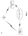
- Fig. 1 illustrates an exemplary network in which methods and systems described herein may be implemented.
- Fig. 2 is an exemplary diagram of the mobile terminal of Fig. 1 .
- Fig. 3 is an exemplary diagram of the handset illustrated in Fig. 2 .
- Fig. 4 is an exemplary diagram illustrating a portion of the satellite companion unit of Fig. 2
- Fig. 5 is an exemplary diagram illustrating portions of the handset and satellite companion unit associated with power mode control.
- Fig. 6 is a flow diagram illustrating exemplary processing consistent with an exemplary implementation.
- Fig. 7 is a schematic diagram illustrating power mode control operations associated with the handset and satellite companion unit.
- a handset of the mobile communication device may be coupled to a satellite companion unit (SCU) that facilitates communication with the satellite-based network.
- the power mode operation of the SCU may be controlled via the handset to conserve power used by the SCU and enhance the battery life of the SCU.
- Fig. 1 is a diagram of an exemplary network 100 in which methods and systems described herein may be implemented.
- network 100 may include mobile terminal 110, communication device 120, terrestrial network 130 and satellite 140.
- the number of devices shown in network 100 is provided for simplicity. It should be understood that network 100 may include additional devices that aid in the transmission and reception of information, as well as additional mobile terminals and communication devices.
- Mobile terminal 110 may include components for transmitting and receiving radio frequency (RF) signals via terrestrial network 130 and satellite 140.
- mobile terminal 110 may include a cellular radiotelephone, a Personal Communications System (PCS) terminal that may combine a cellular radiotelephone with other data processing/communications capabilities; a personal digital assistant (PDA), a conventional laptop and/or palmtop receiver or other appliance that includes a radiotelephone transceiver.
- PCS Personal Communications System
- PDA personal digital assistant
- mobile terminal 110 may be configured to communicate with other devices/systems, such as communication device 120, via terrestrial network 130 and/or via satellite 140.
- mobile terminal 110 may communicate with terrestrial network 130 using, for example, the L-band, the S-band, or another RF band.
- Communication device 120 may include any type of device that is capable of transmitting and receiving voice signals and/or data signals to/from a network.
- communication device 120 may include any conventional telephone that interfaces with, for example, the public switched telephone network (PSTN) or a wireless network to place and receive telephone calls.
- PSTN public switched telephone network
- Communication device 120 may be a standard PSTN-based telephone, a cordless telephone, a cellular telephone, a PDA, a mobile device similar to mobile terminal 110 or another type of conventional telephone.
- Communication device 120 may also include any client, such as a computer device, web-based appliance, etc., that is configured to provide telephone functions.
- client such as a computer device, web-based appliance, etc.
- communication device 120 may be a session initiation protocol (SIP)-based telephone.
- SIP session initiation protocol
- Terrestrial network 130 may include one or more wired and/or wireless networks that are capable of receiving and transmitting data and voice signals.
- terrestrial network 130 may include one or more PSTNs or other type of switched network.
- Terrestrial network 130 may also include packet switched networks, such as the Internet, an intranet, a wide area network (WAN), a metropolitan area network (MAN) or another type of network capable of transmitting data from a source device to a destination device.
- packet switched networks such as the Internet, an intranet, a wide area network (WAN), a metropolitan area network (MAN) or another type of network capable of transmitting data from a source device to a destination device.
- Terrestrial network 130 may also include one or more earth-based cellular networks that include components for transmitting and receiving data and voice signals using RF communications.
- Such components may include base station antennas and transmission towers (not shown) that transmit and receive data from mobile terminals within their vicinity.
- Such components may also include base stations (not shown) that connect to the base station antennas and communicate with other devices, such as switches and routers (not shown) in accordance with known techniques.
- Satellite 140 may represent one of more spaced-based components that are included in a satellite-based network. Satellite 140 may communicate with mobile terminal 110 and other devices in system 100, such as various gateways, routers, etc., that interface with other networks, such as terrestrial network 130. Satellite 140 may communicate with mobile terminal 110 using, for example, the L-band, the S-band, or another RF band.
- Mobile terminal 110 may include components for communicating via terrestrial network 130 and satellite 140.
- mobile terminal 110 may include a handset 210 and a satellite companion unit (SCU) 220, as illustrated in Fig. 2 .
- the term "handset" as used herein may include a radiotelephone device that includes one or more antennas, transmitters and receivers for communicating with a terrestrial network, such as terrestrial network 130.
- handset 210 may be coupled to SCU 220 via connection 230, also referred to herein as cable 230.
- connection 230 may be a wired connection, such as a coaxial cable, a twisted pair connection, etc.
- handset 210 and SCU 220 may include connectors that facilitate easy connecting and/or disconnecting of cable 230 to handset 210 and/or SCU 220.
- the connection from SCU 220 to cable 230 may be a permanent or semi-permanent type connection to help ensure that cable 230 does not get lost.
- handset 210 and SCU 220 may be integrally formed and connection 230 may represent an internal bus/conductor connecting various components associated with handset 210 and SCU 220. In still other implementations, handset 210 may communicate with SCU 220 using wireless communications.
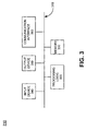
- Fig. 3 is a block diagram illustrating an exemplary configuration of handset 210.
- Handset 210 may include bus 310, processing logic 320, memory 330, input device 340, output device 350 and communication interface 360.
- Bus 310 permits communication among the components of handset 210.
- handset 210 may be configured in a number of other ways and may include other or different elements.
- handset 210 may include one or more power supplies (not shown).
- Handset 210 may also include a modulator, a demodulator, an encoder, a decoder, etc., for processing data.
- Processing logic 320 may include a processor, microprocessor, an application specific integrated circuit (ASIC), field programmable gate array (FPGA) or the like. Processing logic 320 may, in some implementations, execute software instructions/programs or data structures to control operation of mobile terminal 110.
- ASIC application specific integrated circuit
- FPGA field programmable gate array
- Memory 330 may include a random access memory (RAM) or another type of dynamic storage device that stores information and instructions for execution by processing logic 320; a read only memory (ROM) or another type of static storage device that stores static information and instructions for use by processing logic 320; a flash memory (e.g., an electrically erasable programmable read only memory (EEPROM)) device for storing information and instructions; and/or some other type of magnetic or optical recording medium and its corresponding drive. Memory 330 may also be used to store temporary variables or other intermediate information during execution of instructions by processing logic 320. Instructions used by processing logic 320 may also, or alternatively, be stored in another type of computer-readable medium accessible by processing logic 320
- Input device 340 may include one or more mechanisms that permits an operator to input information to handset 210.
- input device may include a microphone, a keyboard, a keypad, a mouse, a pen, voice recognition and/or biometric mechanisms, etc.
- Input device 340 may be used to facilitate placing telephone calls to other devices, carrying on a conversation, etc.
- Output device 350 may include one or more mechanisms that output information to the user, including a display, one or more speakers, a printer, etc. Output device 350 may be used to facilitate receiving telephone calls from other devices, carrying on a conversation, etc.
- Communication interface 360 may include any transceiver-like mechanism that enables handset 210 to communicate with other devices and/or systems.
- communication interface 360 may include an interface, such as an RF connector (e.g., a coaxial connector), to cable 230 or another device.
- Communication interface 360 may also include other mechanisms for communicating via a network, such as a wireless network.
- communication interface 360 may include one or more RF transmitters and receivers and/or transceivers, one or more antennas, etc., used to transmit and receive RF signals, such as RF signals transmitted/received via terrestrial network 130.
- handset 210 may include one or more antennas, transmitters and receivers that enable handset 210 to communicate with terrestrial network 130 using, for example, L band, S band or another RF band.
- Mobile terminal 110 may perform processing associated with communicating via terrestrial network 130 and/or satellite 140, as described in detail below. Mobile terminal 110 may perform these operations in response to processing logic 320 executing sequences of instructions contained in a computer-readable medium, such as memory 330. Such instructions may be read into memory 330 from another computer-readable medium via, for example, communication interface 360.
- a computer-readable medium may include one or more memory devices and/or carrier waves.
- hard-wired circuitry may be used in place of or in combination with software instructions to implement processes consistent with the invention. Thus, implementations consistent with the invention are not limited to any specific combination of hardware circuitry and software.
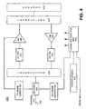
- Fig. 4 illustrates an exemplary configuration of a portion of SCU 220 according to an exemplary implementation.
- SCU 220 may includes antenna 410, transceivers 420 and 430, low noise amplifier (LNA) 440, filters 450 and 452, power amplifier (PA) 460, power source 470, power distribution unit 475, splitter 480, SCU mode sensor 490 and PA mode sensor 494.
- LNA low noise amplifier
- PA power amplifier
- Fig. 4 is provided for simplicity.
- additional elements may be included in SCU 220 that aid in the reception and transmission of signals to, for example, satellite 140.
- Antenna 410 receives and transmits RF signals from/to, for example, satellite 140.
- antenna 410 may receive RF signals in the L-band, S-band, or another band.
- Antenna 410 may forward received signals to transceiver 420, which forwards the signals to LNA 440.
- LNA 440 may amplify the received signals and forward amplified versions of the received signals to filter 450.
- Filter 450 may include a surface acoustic wave (SAW) band pass filter that filters the amplified signals. Filter 450 may then forward the filtered signals to transceiver 430, which forwards the filtered signals to splitter 480.
- SAW surface acoustic wave
- Splitter 480 may function to separate direct current (DC) signals from RF signals. In other words, splitter 480 may act as a high frequency/low frequency splitter. Splitter 480 may pass the RF and/or DC signals to handset 210 via cable 230. Splitter 480 may also receive signals from handset 210. Splitter 480 may forward DC signals to SCU mode sensor 490 and PA mode sensor 494 and RF signals to transceiver 420 with minimal signal attenuation. Based on the signals received from splitter 480, SCU mode sensor 490 may forward an SCU on/off indicator to power distribution unit 475. Splitter 480 may also send a DC signal to PA mode sensor 494, which may forward a PA on/off indication to PA 460.
- DC direct current
- Transceiver 430 may receive RF signals from splitter 480 and forward the RF signals to filter 452.
- Filter 452 may include a SAW BPF that filters the received signals and forwards the filtered signals to PA 460.
- PA 460 when powered up, may amplify the filtered signals and forward the amplified signals to transceiver 420 for transmission via antenna 410.
- SCU 220 may include additional elements, such as modulators, de-modulators, interleavers, error correction logic, etc. Description of such elements is not provided herein in order to not unduly obscure the thrust of the invention.
- Power source 470 may include one or more batteries that provide power to components of SCU 220. Power source 470 may be coupled to power distribution unit 475 that operates in conjunction with SCU mode sensor 490 and PA mode sensor 494 to control the power mode operation of SCU 220 to conserve battery power, as described in detail below.
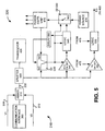
- Fig. 5 is a block diagram illustrating exemplary components of handset 210 and SCU 220 involved in power mode control of SCU 220.
- the portion of handset 210 illustrated includes communication interface 360 and adder 510.
- Adder 510 may be a DC adder circuit that receives various DC signals on lines 512 and 514 based on the operational state of handset 210 and adds these signals.
- adder 510 may receive a steady state DC voltage via line 512, referred to herein as V2, when handset 210 is turned on.
- Adder 510 may also receive a steady state DC voltage via line 514 (e.g., transmitter on signal), referred to herein as V1, when the transmitter portion of handset 210 is turned on/active, such as when handset 210 would like to transmit voice and/or data signals via, for example, satellite 140.
- V1 and V2 may be used to control the power mode operation of SCU 220.
- Adder 510 forwards the DC signals along with RF signals via cable 230 to SCU 220.
- SCU 220 illustrated in Fig. 5 includes switch 1 (S1) 520, switch 2 (S2) 530, SCU on detector 540, logic 545, transmit on detector 550, logic 555, delay element 560, power source 470 and power distribution unit 475.
- SCU mode sensor 490 in Fig. 4 may include elements 540 and 545 and PA mode sensor 494 in Fig. 4 may include elements 550 and 555.
- S1 530 may be, for example, a normally closed, single pole double throw solid state switch that includes a normally closed (NC) contact and a normally open (NO) contact.
- S 1 530 may receive power from power distribution unit 475, based on the state of S2 530.
- S1 530 may also receive a control input from logic 545 via delay element 560.
- SCU on detector 540 may include a detector/comparator circuit that receives input from splitter 480 and S 1 520.
- the input from splitter 480 may be a DC signal having the voltage V2.
- SCU on detector 540 may compare the two inputs (i.e., input from splitter 480 and input from S1 520) and output a control signal to logic 545. For example, when V2 is present, SCU on detector 540 may send a signal to logic 545 indicating that SCU 220 is connected to handset 210.
- Logic 545 may receive the control signal from SCU on detector 540 and forward a control signal to S2 530.
- S2 530 may be, for example, a solid state single pole single throw switch that is normally open.
- logic circuit 545 may signal S2 530 to close its normally open contact. As a result of the closing of S2 530, power from power source 470 may be fed to power distribution unit 475.
- Transmit on detector 550 may include a detector/comparator circuit that receives input from splitter 480 and power distribution unit 475.
- the input from splitter 480 may be a DC signal having voltage V1 + V2.
- Transmit on detector 550 may compare the two inputs (i.e., input from splitter 480 and input from power distribution unit 475) and output a control signal to logic 555.
- Logic 555 may receive power from power distribution unit 475. When the transmitter on signal is detected, logic 555 receives this indication from transmit on detector 550 and outputs a control signal to PA 460 indicating that PA is to be powered up. Processing by components in mobile terminal 110, such as the components illustrated in Figs. 4 and 5 , with respect to controlling the power mode operation of SCU 200 will be described in more detail below.
- Fig. 6 illustrates exemplary processing with respect to controlling the power mode operation of SCU 220.
- the user of mobile terminal 110 wishes to use mobile terminal 110 in a mode associated with receiving and/or transmitting data via satellite 140.
- the user of mobile terminal 110 may couple SCU 220 to handset 210 (act 610).
- handset 210 may be coupled to SCU 220 via cable 230, which may be a wired connection, such as a coaxial cable.
- coaxial connectors may be included on handset 210 and SCU 220 that facilitate easy connection of cable 230 to handset 210.
- connection from cable 230 to SCU 220 may be a permanent or semi-permanent connection to ensure that cable 230 does not become lost.
- the user couples cable 230 to handset 210 and, if necessary, to SCU 220, such that handset 210 and SCU 220 are coupled to each other.
- handset 210 may assert an "SCU ON" signal via line 512 (act 610). For example, when handset 210 is powered on, handset 210 may forward a DC voltage V2 on input line 512 to adder 510. This voltage V2 may function as an SCU ON signal. Adder 510 may forward this signal to splitter 480 via cable 230.
- Splitter 480 may receive this signal, which may be included with RF signals, and extract the DC signal from any RF signals being transmitted via cable 230. Splitter 480 may forward the reference voltage V2 to SCU on detector 540 and transmit on detector 550. SCU on detector 540 may sense the presence of voltage V2 (act 620). The presence of voltage V2 indicates that SCU 220 was successfully connected to handset 210 and that handset 210 is turned "ON". Transmit on detector 550 may take no action based on reception of voltage V2 since transmit on detector 550 is configured to detect a transmitter on signal, as discussed in more detail below.
- SCU 220 switches S 1 520 and S2 530 based on the determination that the SCU on signal was received (act 620). For example, referring to Fig. 5 , SCU on detector 540 may forward a signal to logic 545 indicating that voltage V2 has been detected. Logic 545 may then switch the normally open contact S2 530 to the close position. Closing S2 530 effectively provides power from power source 470 to power distribution unit 475. Logic 545 may also switch the normally open contact at S1 520 to the close position and the normally closed contact at S1 520 to the open position. These control inputs may be forwarded from logic 545 to S1 520 via delay element 560. Delay element 560 may provide, for example, a delay of approximately 100 milliseconds and may prevent possible oscillations in certain transient situations. In other implementations, delay element 560 may not be needed.
- SCU on detector 540, logic 545, switch S1 520 and switch S2 530 are initially powered by voltage from handset 210 through the normally closed (NC) contact of S1 520.
- the switching of the normally open contact S2 530 upon detection of voltage V2 effectively powers SCU 220 in a standby mode (act 630). That is, the closing of S2 530 may provide power from power source 470 to power distribution unit 475, which may then supply power to a number of elements in SCU 220.
- SCU 220 upon detection of signal voltage V2, SCU 220 effectively switches out the source of power from handset 210 for elements 540, 545, 520 and 530 and switches in the source of power internal to SCU 220 (i.e., power source 470). SCU 220 may then operate in a "standby mode" with power distribution unit 475 providing power to, for example, LNA 440, filter 450, transceivers 420 and 430 (in addition to elements 520, 530, 540 and 545), but without powering up various elements associated with transmitting voice and/or data via satellite 140.
- power distribution unit 475 providing power to, for example, LNA 440, filter 450, transceivers 420 and 430 (in addition to elements 520, 530, 540 and 545), but without powering up various elements associated with transmitting voice and/or data via satellite 140.
- all the components illustrated in Fig. 4 may be supplied power from power distribution unit 475 and/or may be active with the exception of PA 460.
- PA 460 may not be powered up or active.
- SCU 220 may receive incoming telephone calls from satellite 140, but may not transmit signals to satellite 140. This may allow SCU 220 to conserve considerable power resources when in the standby mode since PA 460 is not powered up.
- powering SCU 220 in a standby mode in this manner allows SCU 220 to be powered up without the need for an on/off switch. That is, SCU 220 performs an automatic power up based on reception of the SCU on signal from handset 210. This helps simplify operation of SCU 220 by a user.
- the user of mobile terminal 110 wants to make a call while SCU 220 in the standby mode.
- the user of mobile terminal 110 may dial a telephone number via input device 340 (act 640).
- Mobile terminal 110 may then send a "transmitter on" signal to adder 510 via line 514 (act 640).
- the transmitter on signal on line 514 may have a predetermined voltage V1.
- Adder 510 combines the SCU on signal received via line 512 (having a voltage V2) with the transmitter on signal having a voltage V1 to create a combined signal having a voltage V1 + V2.
- Splitter 480 may extract this DC voltage from any RF signals being transmitted via cable 230 and forward the reference voltage V1 + V2 to SCU on detector 540 and transmitter on detector 550.
- SCU on detector 540 may not react to this pulse since it is superimposed on DC voltage V2 and no further action may take place with respect to SCU on detector 540.
- Transmitter on detector 550 senses the reference voltage V1 + V2 as corresponding to a transmitter on signal (act 650).
- transmit on detector 550 may compare the reference voltage V1 + V2 to a reference voltage received from power distribution unit 475 and determine that handset 210 is ready to transmit. Transmit on detector 550 may then signal logic 555 to provide a "power amplifier on" signal to PA 460 (act 650).
- PA 460 may then receive the power amplifier on signal and power up or activate PA 460.
- SCU 220 may forward the RF signals from handset 210 (i.e., voice and/or data signals) through transceiver 430 and filter 452 to PA 460.
- PA 460 may amplify the signals and forward the amplified signals to transceiver 420 for transmission via antenna 410.
- SCU 220 may enter a transmission mode in which signals from handset 210 may be transmitted via SCU 220.
- the transmission mode may represent a full power mode for SCU 220 in which all components needed for reception and transmission, including PA 460, are powered and active.
- SCU 220 may stay in this full power mode as long as handset 210 stays in a transmit mode (e.g., is engaged in a voice telephone call, is engaged in transmitting data, such as text messages, or is engaged in other communications in which transmission is required).
- Transmit on detector 550 senses the absence of voltage V1 and signals logic 555 that the transmitter on signal is no longer present.
- Logic 555 may then send a power amplifier off signal (or de-asserts the power transmitter on signal) to PA 460.
- PA 460 receives the power transmitter off signal (or de-assertion of the PA on signal) and powers off/down PA 460.
- SCU 220 may then re-enter a standby power mode (act 660). As discussed above, in the standby mode, SCU 220 may receive calls, but may not transmit to satellite 140.
- SCU 220 may also include a self turn off feature. For example, assume that handset 210 is turned off or cable 230 is disconnected from handset 210. In this case, handset 210 de-asserts the reference voltage V2 on line 512.
- Splitter 480 as discussed above, forwards the DC component of the signal on cable 230 to SCU on detector 540. In this case, SCU on detector 540 senses the loss of the steady state DC voltage V2 and forwards a signal to logic 545. Logic 545 then switches normally open (NO) contact of S2 530 to open, thereby removing power from power source 470 to power distribution unit 475.
- S 1 520 returns the normally closed (NC) contact to close and the normally open (NO) contact to open. Operation of S1 520 and S2 530, therefore, removes power from components in SCU 220 and SCU 220 enters a power off mode (act 670).
- SCU 220 therefore, returns to an off mode and awaits a signal from handset 210 for future powering up. In this manner, SCU 220 may save power when not in use and/or is not needed.
- Fig. 7 is a schematic diagram illustrating the transition of SCU from an SCU off mode to an SCU standby mode to an SCU full power mode.
- SCU is initially in an off state. In this state, the voltage at SCU is zero volts and power source 470 is not being used. Such a state corresponds to handset 210 being turned off or cable 230 not being connected from handset 210 to SCU 220.
- handset 210 turns on with cable 230 connected to handset 210 or cable 230 may be connected to handset 210 with handset 210 turned on.
- voltage V2 is received at SCU 220 and SCU 220 enters a standby mode.
- handset 210 enters a transmission mode (e.g., the transmitter of handset 210 is active) and voltage V1 + V2 is received by splitter 480.
- SCU 220 may then enter a full power mode with PA 460 powered.
- the transmission mode is terminated (e.g., the transmitter of handset 210 is no longer active), resulting in voltage V2 at splitter 480.
- SCU 220 may then re-enter the standby mode with PA 460 powered down.
- handset 210 may be turned off or cable 230 may be disconnected from handset 210.
- SCU 220 then enters a powered off state in which power source 470 is no longer powering components of SCU 220.
- Systems and methods described herein provide for efficiently powering an SCU with little or no input from a user. This may allow the mobile terminal to conserve power and extend battery life with respect to communicating with a satellite-based network.
- implementations consistent with the invention have been described above with respect to use of a mobile terminal that includes a handset coupled to an SCU for use in hybrid network that utilizes a terrestrial network and a satellite/spaced-based network. It should be understood, however, that implementations consistent with the invention may be used in other types of networks and are not limited to any particular type of network.
- implementations described above refer to a handset and an SCU as being implemented in separate devices. It should also be understood that in some implementations, the functions of the handset and SCU may be included in a single device.
- logic may include hardware, such as a processor, microprocessor, application specific integrated circuit (ASIC) or a field programmable gate array (FPGA), software, or a combination of hardware and software.
- ASIC application specific integrated circuit
- FPGA field programmable gate array
Landscapes
- Engineering & Computer Science (AREA)
- Computer Networks & Wireless Communication (AREA)
- Signal Processing (AREA)
- Physics & Mathematics (AREA)
- Astronomy & Astrophysics (AREA)
- Aviation & Aerospace Engineering (AREA)
- General Physics & Mathematics (AREA)
- Mobile Radio Communication Systems (AREA)
- Radio Relay Systems (AREA)
- Cable Transmission Systems, Equalization Of Radio And Reduction Of Echo (AREA)
- Selective Calling Equipment (AREA)
Claims (14)
- Système, comprenant ; un dispositif radiotéléphonique (210) qui inclut un(e) ou plusieurs antennes, émetteurs et récepteurs et est configuré pour émettre et recevoir des signaux radiofréquence par un réseau terrestre (130) ; et un dispositif de communication par satellite (220) qui inclut une antenne et des émetteurs-récepteurs et est configuré pour émettre et recevoir des signaux radiofréquence par un réseau satellitaire (140), le système étant caractérisé par :le dispositif radiotéléphonique (210) étant couplé au dispositif de communication par satellite (220) par une connexion (230), dans lequel l'unité radiotéléphonique (210) est configurée pour :émettre un premier signal vers le dispositif de communication par satellite (220) lorsque le dispositif radiotéléphonique (210) est allumé et que le dispositif de communication par satellite (220) est connecté à l'unité radiotéléphonique (210) par la connexion (230), le premier signal représentant un signal de commande de premier mode de puissance, etémettre un second signal vers le dispositif de communication par satellite (220) par la connexion (230) lorsque le dispositif radiotéléphonique (210) est dans un mode de transmission, le second signal représentant un signal de commande de second mode de puissance, dans lequel le dispositif de communication par satellite (220) est configuré pour :faire fonctionner le dispositif de communication par satellite (220) dans un premier mode de puissance en réponse à la réception du signal de commande de premier mode de puissance, le premier mode de puissance fournissant de la puissance à une première partie de composants associés à la réception de signaux en provenance d'un satellite, etfaire fonctionner le dispositif de communication par satellite (220) dans un second mode de puissance en réponse à la réception du signal de commande de second mode de puissance, le second mode de puissance fournissant de la puissance à une seconde partie de composants associés à l'émission et à la réception de signaux depuis le satellite.
- Système selon la revendication 1, dans lequel le fonctionnement du dispositif de communication par satellite (220) dans le premier mode de puissance comprend :la fourniture de puissance depuis une source de puissance (470) située à l'intérieur du dispositif de communication par satellite (220) à une première pluralité de composants en réponse au premier signal ; où le fonctionnement du dispositif de communication par satellite (220) dans le second mode de puissance comprend :la fourniture de puissance depuis la source de puissance à une seconde pluralité de composants en réponse au second signal.
- Système selon la revendication 2, dans lequel la première pluralité de composants est un sous-ensemble de la seconde pluralité de composants.
- Système selon la revendication 1, dans lequel le premier signal a une.première tension et le second signal en a une seconde.
- Système selon la revendication 4, dans lequel les première et seconde tensions sont différentes.
- Système selon la revendication 4, dans lequel le dispositif de communication par satellite est en outre configuré pour :recevoir le premier signal, et dans lequel le premier mode de puissance représente moins qu'un mode pleine puissance.
- Système selon la revendication 6, dans lequel le dispositif de communication par satellite est en outre configuré pour ;recevoir le second signal, et dans lequel le second mode de puissance représente le mode pleine puissance.
- Procédé de commande de mode de puissance pour un dispositif de communication comprenant un radiotéléphone (210) qui inclut un(e) ou plusieurs antennes, émetteurs et récepteurs et est configuré pour émettre et recevoir des signaux radiofréquence par un réseau terrestre (130), et un dispositif de communication par satellite (220), couplé au radiotéléphone (210) par une connexion (230), qui inclut une antenne et des émetteurs-récepteurs et est configuré pour émettre et recevoir des signaux radiofréquence par un réseau satellitaire (140), le procédé étant caractérisé par :la transmission d'informations de commande de mode de puissance du radiotéléphone (210) au dispositif de communication par satellite (220) ;la réception des informations de commande de mode de puissance en provenance du radiotéléphone (210) pouréconomiser la puissance utilisée par le dispositif de communication par satellite (220) ; etfournir de la puissance à des composants du dispositif de communication par satellite (220) depuis une source de puissance (470) située à l'intérieur du dispositif de communication par satellite (220) sur la base des informations de commande de mode de puissance afin de prolonger la durée de vie de la source de puissance (470), où la fourniture de puissance comprend :le fonctionnement du dispositif de communication par satellite (220) dans un premier mode de puissance en réponse aux informations de commande de premier mode de puissance reçues par le dispositif de communication par satellite (220) lorsque le dispositif radiotéléphonique (210) est allumé et est couplé au dispositif de communication par satellite (220) par la connexion (230), le premier mode de puissance représentant un mode de veille dans lequel le dispositif de communication par satellite (220) est configuré pour recevoir des signaux par le réseau satellitaire, etle fonctionnement du dispositif de communication par satellite (220) dans un second mode de puissance en réponse aux informations de commande de second mode de puissance reçues par le dispositif de communication par satellite (220) lorsque le radiotéléphone (210) est dans un mode de transmission associé à l'émission de signaux par le réseau satellitaire.
- Procédé selon la revendication 8, comprenant en outre :la mise hors tension du dispositif de communication par satellite lorsque le radiotéléphone est éteint ou lorsque le dispositif de communication par satellite est déconnecté du radiotéléphone.
- Procédé selon la revendication 8, comprenant en outre :l'activation d'un amplificateur de puissance associé à l'émission de signaux vers le réseau satellitaire sur la base des informations de commande de second mode de puissance en provenance du radiotéléphone.
- Procédé selon la revendication 8, dans lequel la réception des informations de commande de mode de puissance comprend :la réception d'un premier signal ayant une première tension lorsque le radiotéléphone est couplé au dispositif de communication par satellite ; etla détermination que le radiotéléphone est couplé au dispositif de communication par satellite et que le radiotéléphone est allumé en réponse à la réception du premier signal ;dans lequel le fonctionnement du dispositif de communication par satellite dans le premier mode de puissance comprend :la connexion de la source de puissance à une pluralité de composants à l'intérieur du dispositif de communication par satellite en réponse à la réception du premier signal.
- Procédé selon la revendication 11, dans lequel la réception des informations de commande de mode de puissance comprend en outre :la réception d'un second signal ayant une seconde tension lorsque le radiotéléphone est couplé au dispositif de communication par satellite ; etla détermination que le radiotéléphone est dans le mode de transmission en réponse à la réception du second signal ;dans lequel le fonctionnement du dispositif de communication par satellite dans le second mode de puissance comprend :l'activation d'au moins un premier composant situé à l'intérieur du dispositif de communication par satellite, le premier composant étant associé à l'émission des signaux radiofréquence.
- Procédé selon la revendication 12, dans lequel l'activation d'au moins un premier composant comprend la mise sous tension d'un amplificateur de puissance.
- Procédé selon la revendication 8, comprenant en outre :l'émission de signaux de voix ou de données vers un satellite inclus dans le réseau satellitaire lorsque le dispositif de communication par satellite est dans le second mode de puissance ; et la réception de signaux de voix ou de données en provenance du satellite lorsque le dispositif de communication par satellite est dans le second mode de puissance.
Applications Claiming Priority (2)
| Application Number | Priority Date | Filing Date | Title |
|---|---|---|---|
| US70152105P | 2005-07-22 | 2005-07-22 | |
| PCT/US2006/028136 WO2007013956A2 (fr) | 2005-07-22 | 2006-07-21 | Commande de mode de puissance pour un dispositif de communication |
Publications (2)
| Publication Number | Publication Date |
|---|---|
| EP1908188A2 EP1908188A2 (fr) | 2008-04-09 |
| EP1908188B1 true EP1908188B1 (fr) | 2010-05-19 |
Family
ID=37499613
Family Applications (1)
| Application Number | Title | Priority Date | Filing Date |
|---|---|---|---|
| EP06787937A Active EP1908188B1 (fr) | 2005-07-22 | 2006-07-21 | Commande de mode de puissance pour un dispositif de communication |
Country Status (7)
| Country | Link |
|---|---|
| US (1) | US9161312B2 (fr) |
| EP (1) | EP1908188B1 (fr) |
| AT (1) | ATE468664T1 (fr) |
| CA (1) | CA2616017C (fr) |
| DE (1) | DE602006014410D1 (fr) |
| MX (1) | MX2008000879A (fr) |
| WO (1) | WO2007013956A2 (fr) |
Families Citing this family (1)
| Publication number | Priority date | Publication date | Assignee | Title |
|---|---|---|---|---|
| TW200638778A (en) * | 2005-04-26 | 2006-11-01 | Z Com Inc | Wireless network device with signal detection function and switching method for the same |
Family Cites Families (21)
| Publication number | Priority date | Publication date | Assignee | Title |
|---|---|---|---|---|
| EP0728383B1 (fr) * | 1994-09-14 | 2007-08-22 | Ericsson Inc. | Adaptateur de telecommunications par satellite pour combine cellulaire |
| US5930679A (en) | 1994-10-03 | 1999-07-27 | Motorola, Inc. | Satellite-based ring alert apparatus and method of use |
| JP3231589B2 (ja) * | 1995-09-13 | 2001-11-26 | 三菱電機株式会社 | 衛星通信端末システム |
| US6141688A (en) * | 1995-10-16 | 2000-10-31 | Nec Corporation | Broadcast search for available host |
| US5854784A (en) * | 1996-11-05 | 1998-12-29 | Ericsson, Inc. | Power-saving method for providing synchronization in a communications system |
| US5978366A (en) | 1996-12-20 | 1999-11-02 | Ericsson Inc. | Methods and systems for reduced power operation of cellular mobile terminals |
| US5995041A (en) | 1996-12-30 | 1999-11-30 | At&T Corp. | Communication system with direct link to satellite |
| GB9721008D0 (en) * | 1997-10-03 | 1997-12-03 | Hewlett Packard Co | Power management method foruse in a wireless local area network (LAN) |
| US6085090A (en) * | 1997-10-20 | 2000-07-04 | Motorola, Inc. | Autonomous interrogatable information and position device |
| US6088589A (en) * | 1997-12-11 | 2000-07-11 | Ericsson Inc. | System, method and apparatus for handling high-power notification messages |
| US6163679A (en) * | 1998-09-08 | 2000-12-19 | Motorola, Inc. | Method and apparatus for system acquisition for a subscriber unit |
| EP1059826A4 (fr) * | 1998-12-07 | 2005-08-03 | Mitsubishi Electric Corp | Dispositif de communication mobile et systeme de communication mobile |
| US6690947B1 (en) * | 1999-03-25 | 2004-02-10 | Kantan Inc. | Methods and apparatus for a flexible wireless communication and cellular telephone system |
| US6501969B1 (en) * | 1999-05-05 | 2002-12-31 | Agere Systems Inc. | Extended power savings for electronic devices |
| US6487264B1 (en) * | 1999-05-12 | 2002-11-26 | Xetron Corporation | RF modem apparatus |
| US6490458B1 (en) * | 1999-06-16 | 2002-12-03 | Verizon Laboratories Inc. | Portable phone bank |
| US20020119796A1 (en) * | 2000-12-29 | 2002-08-29 | Telefonaktiebolaget Lm Ericsson | System and method for improved mobile communication admission and congestion control |
| US6763226B1 (en) * | 2002-07-31 | 2004-07-13 | Computer Science Central, Inc. | Multifunctional world wide walkie talkie, a tri-frequency cellular-satellite wireless instant messenger computer and network for establishing global wireless volp quality of service (qos) communications, unified messaging, and video conferencing via the internet |
| FI20030929L (fi) * | 2003-06-19 | 2004-12-20 | Nokia Corp | Menetelmä ja järjestelyjä langattoman tiedonsiirron toteuttamiseksi kulkuvälineessä |
| US7991399B2 (en) * | 2004-01-06 | 2011-08-02 | Vasu Networks Corporation | Telephone with automatic switching between cellular and VoIP networks |
| TWI248568B (en) * | 2004-05-24 | 2006-02-01 | Avision Inc | Power-saving system of computer peripheral apparatus |
-
2006
- 2006-07-21 WO PCT/US2006/028136 patent/WO2007013956A2/fr not_active Ceased
- 2006-07-21 CA CA2616017A patent/CA2616017C/fr active Active
- 2006-07-21 AT AT06787937T patent/ATE468664T1/de not_active IP Right Cessation
- 2006-07-21 DE DE602006014410T patent/DE602006014410D1/de not_active Expired - Fee Related
- 2006-07-21 MX MX2008000879A patent/MX2008000879A/es active IP Right Grant
- 2006-07-21 US US11/490,166 patent/US9161312B2/en active Active
- 2006-07-21 EP EP06787937A patent/EP1908188B1/fr active Active
Also Published As
| Publication number | Publication date |
|---|---|
| EP1908188A2 (fr) | 2008-04-09 |
| ATE468664T1 (de) | 2010-06-15 |
| DE602006014410D1 (de) | 2010-07-01 |
| CA2616017C (fr) | 2014-10-07 |
| WO2007013956A2 (fr) | 2007-02-01 |
| WO2007013956A3 (fr) | 2007-08-02 |
| CA2616017A1 (fr) | 2007-02-01 |
| US9161312B2 (en) | 2015-10-13 |
| US20070021062A1 (en) | 2007-01-25 |
| MX2008000879A (es) | 2008-10-15 |
Similar Documents
| Publication | Publication Date | Title |
|---|---|---|
| US6442375B1 (en) | Systems and methods for maintaining operation of a receiver co-located with a transmitter and susceptible to interference therefrom by desensitization of the receiver | |
| US6445937B1 (en) | Methods and apparatus for mobile phone power management | |
| JP3095414B2 (ja) | 複数の動作モードを有する携帯通信およびデータ端末 | |
| US7979097B2 (en) | Power management for multimode wireless communication device | |
| US20070155344A1 (en) | Wireless multimode co-band receiver device and method employing receiver bypass control | |
| US7379753B2 (en) | Method and apparatus for communication, and computer product | |
| US8472998B2 (en) | System and method for achieving WLAN communications between access point and mobile device | |
| US20030227939A1 (en) | Establishing a connection using a hybrid receiver | |
| US20090098869A1 (en) | Power saving | |
| JPH1013333A (ja) | 移動体通信装置 | |
| US20040192406A1 (en) | Antenna circuit and wireless communication device | |
| WO2007147337A1 (fr) | Terminal sans fil bimode et procédé de réalisation simultanée de deux types de mode de communication | |
| US20040214607A1 (en) | Cellular phone terminal, antenna changeover control method, and program | |
| JP3789432B2 (ja) | 移動通信システム及び複合携帯端末 | |
| JP2001268211A (ja) | 電話機用ハンズフリー装置 | |
| EP1908188B1 (fr) | Commande de mode de puissance pour un dispositif de communication | |
| US20040235537A1 (en) | Radio communications apparatus | |
| EP2341702A1 (fr) | Dispositif électronique sans fil avec contrôle d'alimentation automatique | |
| US9402173B2 (en) | Methods and apparatus for providing access to emergency service providers | |
| KR100251540B1 (ko) | 이동통신 시스템의 대기통화 방법 및 장치 | |
| JP2008193289A (ja) | 電波増幅器および無線lanアクセスポイント | |
| JP2006246342A (ja) | 携帯電話機 | |
| JPH0643979A (ja) | 携帯形電子機器およびその電源回路 | |
| US8255008B1 (en) | Mobile terminal equipped with automatic power supply | |
| JPS6313525A (ja) | 携帯無線機 |
Legal Events
| Date | Code | Title | Description |
|---|---|---|---|
| PUAI | Public reference made under article 153(3) epc to a published international application that has entered the european phase |
Free format text: ORIGINAL CODE: 0009012 |
|
| 17P | Request for examination filed |
Effective date: 20080211 |
|
| AK | Designated contracting states |
Kind code of ref document: A2 Designated state(s): AT BE BG CH CY CZ DE DK EE ES FI FR GB GR HU IE IS IT LI LT LU LV MC NL PL PT RO SE SI SK TR |
|
| 17Q | First examination report despatched |
Effective date: 20080602 |
|
| GRAP | Despatch of communication of intention to grant a patent |
Free format text: ORIGINAL CODE: EPIDOSNIGR1 |
|
| GRAS | Grant fee paid |
Free format text: ORIGINAL CODE: EPIDOSNIGR3 |
|
| GRAA | (expected) grant |
Free format text: ORIGINAL CODE: 0009210 |
|
| DAX | Request for extension of the european patent (deleted) | ||
| AK | Designated contracting states |
Kind code of ref document: B1 Designated state(s): AT BE BG CH CY CZ DE DK EE ES FI FR GB GR HU IE IS IT LI LT LU LV MC NL PL PT RO SE SI SK TR |
|
| REG | Reference to a national code |
Ref country code: GB Ref legal event code: FG4D |
|
| REG | Reference to a national code |
Ref country code: CH Ref legal event code: EP |
|
| REG | Reference to a national code |
Ref country code: IE Ref legal event code: FG4D |
|
| REF | Corresponds to: |
Ref document number: 602006014410 Country of ref document: DE Date of ref document: 20100701 Kind code of ref document: P |
|
| REG | Reference to a national code |
Ref country code: NL Ref legal event code: VDEP Effective date: 20100519 |
|
| LTIE | Lt: invalidation of european patent or patent extension |
Effective date: 20100519 |
|
| PG25 | Lapsed in a contracting state [announced via postgrant information from national office to epo] |
Ref country code: SE Free format text: LAPSE BECAUSE OF FAILURE TO SUBMIT A TRANSLATION OF THE DESCRIPTION OR TO PAY THE FEE WITHIN THE PRESCRIBED TIME-LIMIT Effective date: 20100519 Ref country code: LT Free format text: LAPSE BECAUSE OF FAILURE TO SUBMIT A TRANSLATION OF THE DESCRIPTION OR TO PAY THE FEE WITHIN THE PRESCRIBED TIME-LIMIT Effective date: 20100519 Ref country code: ES Free format text: LAPSE BECAUSE OF FAILURE TO SUBMIT A TRANSLATION OF THE DESCRIPTION OR TO PAY THE FEE WITHIN THE PRESCRIBED TIME-LIMIT Effective date: 20100830 |
|
| PG25 | Lapsed in a contracting state [announced via postgrant information from national office to epo] |
Ref country code: AT Free format text: LAPSE BECAUSE OF FAILURE TO SUBMIT A TRANSLATION OF THE DESCRIPTION OR TO PAY THE FEE WITHIN THE PRESCRIBED TIME-LIMIT Effective date: 20100519 Ref country code: SI Free format text: LAPSE BECAUSE OF FAILURE TO SUBMIT A TRANSLATION OF THE DESCRIPTION OR TO PAY THE FEE WITHIN THE PRESCRIBED TIME-LIMIT Effective date: 20100519 Ref country code: LV Free format text: LAPSE BECAUSE OF FAILURE TO SUBMIT A TRANSLATION OF THE DESCRIPTION OR TO PAY THE FEE WITHIN THE PRESCRIBED TIME-LIMIT Effective date: 20100519 Ref country code: IS Free format text: LAPSE BECAUSE OF FAILURE TO SUBMIT A TRANSLATION OF THE DESCRIPTION OR TO PAY THE FEE WITHIN THE PRESCRIBED TIME-LIMIT Effective date: 20100919 Ref country code: FI Free format text: LAPSE BECAUSE OF FAILURE TO SUBMIT A TRANSLATION OF THE DESCRIPTION OR TO PAY THE FEE WITHIN THE PRESCRIBED TIME-LIMIT Effective date: 20100519 |
|
| PG25 | Lapsed in a contracting state [announced via postgrant information from national office to epo] |
Ref country code: CY Free format text: LAPSE BECAUSE OF FAILURE TO SUBMIT A TRANSLATION OF THE DESCRIPTION OR TO PAY THE FEE WITHIN THE PRESCRIBED TIME-LIMIT Effective date: 20100526 Ref country code: PL Free format text: LAPSE BECAUSE OF FAILURE TO SUBMIT A TRANSLATION OF THE DESCRIPTION OR TO PAY THE FEE WITHIN THE PRESCRIBED TIME-LIMIT Effective date: 20100519 Ref country code: GR Free format text: LAPSE BECAUSE OF FAILURE TO SUBMIT A TRANSLATION OF THE DESCRIPTION OR TO PAY THE FEE WITHIN THE PRESCRIBED TIME-LIMIT Effective date: 20100820 |
|
| PG25 | Lapsed in a contracting state [announced via postgrant information from national office to epo] |
Ref country code: DK Free format text: LAPSE BECAUSE OF FAILURE TO SUBMIT A TRANSLATION OF THE DESCRIPTION OR TO PAY THE FEE WITHIN THE PRESCRIBED TIME-LIMIT Effective date: 20100519 Ref country code: PT Free format text: LAPSE BECAUSE OF FAILURE TO SUBMIT A TRANSLATION OF THE DESCRIPTION OR TO PAY THE FEE WITHIN THE PRESCRIBED TIME-LIMIT Effective date: 20100920 Ref country code: NL Free format text: LAPSE BECAUSE OF FAILURE TO SUBMIT A TRANSLATION OF THE DESCRIPTION OR TO PAY THE FEE WITHIN THE PRESCRIBED TIME-LIMIT Effective date: 20100519 Ref country code: EE Free format text: LAPSE BECAUSE OF FAILURE TO SUBMIT A TRANSLATION OF THE DESCRIPTION OR TO PAY THE FEE WITHIN THE PRESCRIBED TIME-LIMIT Effective date: 20100519 |
|
| PG25 | Lapsed in a contracting state [announced via postgrant information from national office to epo] |
Ref country code: CZ Free format text: LAPSE BECAUSE OF FAILURE TO SUBMIT A TRANSLATION OF THE DESCRIPTION OR TO PAY THE FEE WITHIN THE PRESCRIBED TIME-LIMIT Effective date: 20100519 Ref country code: BE Free format text: LAPSE BECAUSE OF FAILURE TO SUBMIT A TRANSLATION OF THE DESCRIPTION OR TO PAY THE FEE WITHIN THE PRESCRIBED TIME-LIMIT Effective date: 20100519 Ref country code: RO Free format text: LAPSE BECAUSE OF FAILURE TO SUBMIT A TRANSLATION OF THE DESCRIPTION OR TO PAY THE FEE WITHIN THE PRESCRIBED TIME-LIMIT Effective date: 20100519 Ref country code: SK Free format text: LAPSE BECAUSE OF FAILURE TO SUBMIT A TRANSLATION OF THE DESCRIPTION OR TO PAY THE FEE WITHIN THE PRESCRIBED TIME-LIMIT Effective date: 20100519 Ref country code: MC Free format text: LAPSE BECAUSE OF NON-PAYMENT OF DUE FEES Effective date: 20100731 |
|
| REG | Reference to a national code |
Ref country code: CH Ref legal event code: PL |
|
| PLBE | No opposition filed within time limit |
Free format text: ORIGINAL CODE: 0009261 |
|
| STAA | Information on the status of an ep patent application or granted ep patent |
Free format text: STATUS: NO OPPOSITION FILED WITHIN TIME LIMIT |
|
| PG25 | Lapsed in a contracting state [announced via postgrant information from national office to epo] |
Ref country code: IT Free format text: LAPSE BECAUSE OF FAILURE TO SUBMIT A TRANSLATION OF THE DESCRIPTION OR TO PAY THE FEE WITHIN THE PRESCRIBED TIME-LIMIT Effective date: 20100519 |
|
| REG | Reference to a national code |
Ref country code: FR Ref legal event code: ST Effective date: 20110331 |
|
| 26N | No opposition filed |
Effective date: 20110222 |
|
| PG25 | Lapsed in a contracting state [announced via postgrant information from national office to epo] |
Ref country code: CH Free format text: LAPSE BECAUSE OF NON-PAYMENT OF DUE FEES Effective date: 20100731 Ref country code: LI Free format text: LAPSE BECAUSE OF NON-PAYMENT OF DUE FEES Effective date: 20100731 Ref country code: DE Free format text: LAPSE BECAUSE OF NON-PAYMENT OF DUE FEES Effective date: 20110201 |
|
| REG | Reference to a national code |
Ref country code: DE Ref legal event code: R119 Ref document number: 602006014410 Country of ref document: DE Effective date: 20110201 |
|
| PG25 | Lapsed in a contracting state [announced via postgrant information from national office to epo] |
Ref country code: FR Free format text: LAPSE BECAUSE OF NON-PAYMENT OF DUE FEES Effective date: 20100802 |
|
| PG25 | Lapsed in a contracting state [announced via postgrant information from national office to epo] |
Ref country code: IE Free format text: LAPSE BECAUSE OF NON-PAYMENT OF DUE FEES Effective date: 20100721 |
|
| PG25 | Lapsed in a contracting state [announced via postgrant information from national office to epo] |
Ref country code: LU Free format text: LAPSE BECAUSE OF NON-PAYMENT OF DUE FEES Effective date: 20100721 Ref country code: HU Free format text: LAPSE BECAUSE OF FAILURE TO SUBMIT A TRANSLATION OF THE DESCRIPTION OR TO PAY THE FEE WITHIN THE PRESCRIBED TIME-LIMIT Effective date: 20101120 Ref country code: BG Free format text: LAPSE BECAUSE OF FAILURE TO SUBMIT A TRANSLATION OF THE DESCRIPTION OR TO PAY THE FEE WITHIN THE PRESCRIBED TIME-LIMIT Effective date: 20100519 |
|
| PG25 | Lapsed in a contracting state [announced via postgrant information from national office to epo] |
Ref country code: TR Free format text: LAPSE BECAUSE OF FAILURE TO SUBMIT A TRANSLATION OF THE DESCRIPTION OR TO PAY THE FEE WITHIN THE PRESCRIBED TIME-LIMIT Effective date: 20100519 |
|
| PG25 | Lapsed in a contracting state [announced via postgrant information from national office to epo] |
Ref country code: BG Free format text: LAPSE BECAUSE OF FAILURE TO SUBMIT A TRANSLATION OF THE DESCRIPTION OR TO PAY THE FEE WITHIN THE PRESCRIBED TIME-LIMIT Effective date: 20100819 |
|
| PGFP | Annual fee paid to national office [announced via postgrant information from national office to epo] |
Ref country code: GB Payment date: 20250728 Year of fee payment: 20 |