EP1908148B1 - Electrical contact between high or medium voltage apparatuses that is capable of swiveling - Google Patents
Electrical contact between high or medium voltage apparatuses that is capable of swiveling Download PDFInfo
- Publication number
- EP1908148B1 EP1908148B1 EP06777888A EP06777888A EP1908148B1 EP 1908148 B1 EP1908148 B1 EP 1908148B1 EP 06777888 A EP06777888 A EP 06777888A EP 06777888 A EP06777888 A EP 06777888A EP 1908148 B1 EP1908148 B1 EP 1908148B1
- Authority
- EP
- European Patent Office
- Prior art keywords
- recess
- spring
- axis
- bar
- contact
- Prior art date
- Legal status (The legal status is an assumption and is not a legal conclusion. Google has not performed a legal analysis and makes no representation as to the accuracy of the status listed.)
- Not-in-force
Links
Images
Classifications
-
- H—ELECTRICITY
- H01—ELECTRIC ELEMENTS
- H01R—ELECTRICALLY-CONDUCTIVE CONNECTIONS; STRUCTURAL ASSOCIATIONS OF A PLURALITY OF MUTUALLY-INSULATED ELECTRICAL CONNECTING ELEMENTS; COUPLING DEVICES; CURRENT COLLECTORS
- H01R13/00—Details of coupling devices of the kinds covered by groups H01R12/70 or H01R24/00 - H01R33/00
- H01R13/62—Means for facilitating engagement or disengagement of coupling parts or for holding them in engagement
- H01R13/629—Additional means for facilitating engagement or disengagement of coupling parts, e.g. aligning or guiding means, levers, gas pressure electrical locking indicators, manufacturing tolerances
-
- H—ELECTRICITY
- H01—ELECTRIC ELEMENTS
- H01R—ELECTRICALLY-CONDUCTIVE CONNECTIONS; STRUCTURAL ASSOCIATIONS OF A PLURALITY OF MUTUALLY-INSULATED ELECTRICAL CONNECTING ELEMENTS; COUPLING DEVICES; CURRENT COLLECTORS
- H01R13/00—Details of coupling devices of the kinds covered by groups H01R12/70 or H01R24/00 - H01R33/00
- H01R13/02—Contact members
- H01R13/15—Pins, blades or sockets having separate spring member for producing or increasing contact pressure
- H01R13/187—Pins, blades or sockets having separate spring member for producing or increasing contact pressure with spring member in the socket
-
- H—ELECTRICITY
- H02—GENERATION; CONVERSION OR DISTRIBUTION OF ELECTRIC POWER
- H02G—INSTALLATION OF ELECTRIC CABLES OR LINES, OR OF COMBINED OPTICAL AND ELECTRIC CABLES OR LINES
- H02G5/00—Installations of bus-bars
- H02G5/06—Totally-enclosed installations, e.g. in metal casings
- H02G5/063—Totally-enclosed installations, e.g. in metal casings filled with oil or gas
Definitions
- the invention relates to the field of connection between electrical appliances.
- This type of connection between electrical devices is such that the electrical contact is permanent except for assembly or maintenance operations, and the interlocking is semi-fixed.
- the invention relates to the possibility of interlocking ensuring the electrical and mechanical functions between two relatively movable parts of a contact block, although the two parts are deliberately not adjusted, so that it is possible to tilt them relative to each other.
- the invention finds a particular application for electrical appliances with high or medium voltage; it reduces costs during assembly / disassembly operations.
- contact blocks For the transmission of current between high and medium voltage switchgear, contact blocks usually comprise two mutually movable parts connected to different elements of the switchgear to ensure the transmission of the electric current. . Mobility between both parts are only used for assembly and disassembly operations.
- a first part for example a bar provided with an electrical contact at at least one end, is movable in translation to be connected to a fixed contact, usually comprising a cylindrical recess in which the bar is inserted to be held in position .
- a fixed contact usually comprising a cylindrical recess in which the bar is inserted to be held in position .
- the interlocking of the bar in the fixed contact of the contact block thus ensures the electrical connection and mechanical maintenance.
- the bars, rigid can be very heavy, for example of the order of a hundred kilograms, the mechanical load exerted on the fixed contact is important.
- the movable and fixed parts are perfectly coaxial and adjusted to ensure the best electrical contact possible when the devices are assembled, that is to say that the bar is nested in the fixed contact. But misalignment is possible between devices assembled together, and a game between the two parties can be advocated.
- the invention proposes, among other advantages, to overcome the disadvantages described above, and in particular to allow an inclination between the fixed contact and the movable contact, that is to say between the bar and the contact recess. According to the invention, this possibility of “swiveling” is exploited during assembly / disassembly operations, during which it is possible to tilt the connecting bar with respect to the axis of the fixed contact, thus allowing the omission of telescopic elements and removable bars.
- the invention relates to an electrical connection device characterized in that it comprises two high and / or medium voltage contact blocks, each contact block comprising a first tubular portion extending along a first axis, a second part comprising a cylindrical recess around a second axis such that the first part can fit into the recess, and movable connection means between the first and second parts adapted for, when the first part is inserted into the recess , allow inclination of an angle ⁇ between the first and second axes around the second axis and ensure contact between the first and second axes and second parts, the first tubular portion of the first and second blocks being a single bar.
- the invention thus makes it possible simultaneously to have an efficient electrical contact in a small space and a possibility of inclination between the current conducting bar and the fixed contact. Thanks to the invention, a "high performance" electrical contact can be obtained in a small space: this type of contact is in particular adapted at least for a permanent current between 2000 and 6300 A, in particular greater than 4000 A, and a short-circuit current of 31.5 to 63 kA for 3 s.
- the invention relates to a connection of two parts fitting and movable relative to each other, comprising elements to compensate for their play and to tilt one of the parts relative to the other. while maintaining their function.
- the invention thus relates to a contact block for high or medium voltage electrical apparatus, comprising two relatively movable parts, in particular a rigid tube fitting into a recess provided with a projection.
- the dimensions of the two parts are such that a game is present between them, so that the axes of the two parts can not be confused.
- the bar may be inclined relative to the second part, preferably at an angle of the order of 4 °, or less than 7 °. This inclination, equivalent in fact to an additional degree of freedom, facilitates the insertion and removal of the movable part by greater flexibility with respect to alignment constraints.
- Electrically conductive and resilient elements are present in the block to compensate for each of the games between first and second portions; two spring elements are located in the same radial plane to form a pair.
- the spring elements are advantageously positioned on only one part of the block, in particular on each side of the bar or face to face in the recess (on the wall and the inner projection).
- the spring elements are annular.
- the spring elements may be slat strips or inclined coil springs.
- the spring elements usually metal, can be associated locally to mechanical connection supports, for example three pieces of polyamide which can support the bar if necessary, avoiding the generation of chips due to the metal-to-metal friction between the bar and the recess, or between the bar and the central projection .
- the invention relates to the use of this faculty of "swiveling" in a high or medium voltage device for the connection of electrical contacts.
- connection device comprising a bar secured at each end to an electrical device in a contact block as previously defined.
- a contact block according to the invention can be used mainly for a connection between two high or medium voltage devices, in which case it is located at the periphery of the devices: in fact, a bar connects two devices via two connections to each of its ends.
- the connection usually established, can be interrupted, especially for maintenance operations: the bar must then be disconnected from one of the devices, to which it is connected in a block according to the invention.
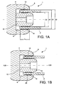
- an electrical connection block 1 of a high or medium voltage device comprises two parts movable relative to each other.
- the first part 2, or bar is usually in the form of a rigid metal cylindrical tube, for example aluminum or copper.
- the tube 2 is of revolution about an axis AA and has an external diameter D1 and an internal diameter d1, defining a substantially constant wall thickness, at least at the end portion fitting into the fixed part of the block 1.
- the bar 2 may be aluminum with a thickness of 5 to 15 mm, and an outside diameter D1 of between 50 and 200 mm, these dimensions relating to the ends of the bar 2 which may for example also include protuberances along its length; the length of this first part 2 depends on the use, it varies from about 300 mm to 10 m or even 12 meters; the mass of each bar can thus be of the order of 200 kg.
- the first part 2 When the high or medium voltage switchgear is assembled, the first part 2 is coupled with a fixed contact 4 (although represented for one end, a tube 2 may in particular be connected at each of its ends to a "fixed" contact 4 thus forming an assembly in which the first and second contact blocks 1 are such that their first parts 2 are connected and unitary in a bar).
- This second part of the connection block 1 usually comprises a support secured to an element of the apparatus and provided with a recess 6 in which the bar 2 is inserted.
- the recess 6 is delimited by a wall, usually cylindrical of revolution. around its axis BB, a cylindrical ring 8 extending over a length L provides a mechanical support of the bar 2; for the example above, the length L can thus be of the order of 50 mm.
- the wall is dimensioned so that the bar 2 can slide easily, i.e. the inner diameter d2 of the holding wall portion 8 (the narrowest) is greater than the outer diameter D1 of the first part 2.
- a central insert 10 projecting into the recess 6 is for example used for the electrical connection as such.
- the insert is of shape and size adapted so that the first part 2 fits around, that is to say that the insert 10 extends symmetrically about the axis BB of the second part 4 and the outer diameter D2 of the insert 10 is smaller than the internal diameter d1 of the bar 2.
- D1 130 mm
- D2 75 mm
- d1 77 mm
- D1 97 mm
- d2 99 mm
- L 45 mm.
- spring elements in particular conductors, are provided.
- Each spring element is arranged in pairs of elements 12, 14 facing each side of the first part 2, and in the same radial plane to the axes AA, BB; a pair of spring elements 12, 14 compensates for the clearance between first and second parts 2, 4.
- the pairs of elements 12, 14 springing can be located on the two parts of the block 1, advantageously, in order to simplify the construction and ensure their position vis-à-vis on the same plane, it is preferable that the pairs are located on the same part.
- the first part 2 is a conventional bar
- the pairs of spring elements 12, 14 are positioned vis-à-vis the cylindrical wall 8 and the insert 10. It is possible, as illustrated in FIG. Figure 1B , positioning the two spring elements 12, 14 of each pair on the outer and inner faces of the tubular wall of the first part 2.
- the spring elements 12, 14 of each pair may be the same or different. They can extend over a variable length of arc.
- this arc length is less than 180 °, a plurality of pairs of spring elements is disposed on the periphery of the contact block 1 so that the compensation is homogeneous; for example, one can find three pairs at 120 ° from each other, or four from 90 °, etc.
- At least one of the spring elements 12, 14 is annular, that is to say that it covers the entire periphery of the part concerned, and extends on a radial plane to its axis.
- the second element can extend over an arc length only (in which case it is also possible to find several pairs face to face, by "cutting" arbitrarily the annular element), or preferably also be annular.
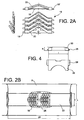
- a preferred embodiment is the use of strip strips, as described for example in the document EP 1 119 077 and illustrated in the Figure 2A .
- These flap strips 16 comprise a thin metal strip 18 with a width of the order of 26 to 30 mm for example; on this strip 18 is positioned a succession of triangular metal strips 20, of thickness less than 5 mm, usually projecting from the plane of the strip 18 at a maximum angle of less than 90 °, and being able to be lowered towards the strip 18 in case of pressure.
- the working height of the slats 20 can thus vary for example between 5 mm maximum height in the active position and 2.5 mm, or less.
- Such a strip 16 is inserted by insertion into a groove 22 which may be straight, or preferably T-shaped or dovetail if the strips 20 leave a portion 18 'of the free band at each end for its keeping in the throat 22: see figures 1 , 2B .
- the inclination of the slats 20 thus compensates for a variable clearance, for example 2.5 mm, while maintaining an electrical contact.
- the strip 16 is placed in a groove 22 located centrally with respect to the holding wall 8 of the connection block (see also Figure 2B ).
- a groove 22 located centrally with respect to the holding wall 8 of the connection block (see also Figure 2B ).
- the depth of the groove 22 is adapted to obtain a satisfactory swiveling angle, while remaining within the range of operation of the slats.
- the spring element 12, 14 may also for example be a " canted coil " type spring ( WO 2004/031595 ), that is to say an annular spring inclined turns, which can also be positioned in a groove made in the corresponding part; similarly, during insertion, the turns of the spring tilt more or less to allow connection.
- the contact blocks according to the invention thus allow a better machining tolerance, while ensuring the electrical and mechanical functions inherent to their nature.
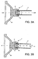
- the block according to the invention it is also possible, as illustrated on the figures 3 , tilting the first portion 2 relative to the second portion 4, at an angle ⁇ , while the contact block 1 is associated, here via a support 24, to a high or medium voltage switchgear.
- the angle ⁇ allowed varies between 1 and 7 °, for example 4 °, and the different dimensions d1, D1, d2, D2, L are chosen for this purpose; the inclination can be performed in all directions around the axis BB.
- connection block makes it possible to perform assembly and dismounting functions of the connection block more easily, and to lower cost: in most cases, it is no longer necessary to have removable links between the devices, usually consisting of telescopic ferrules and removable bars.
- a permanent current between 2000 A and 6300 A can be provided by a bar 2 of mass up to about 200 kg secured to two fixed elements 4, preferably of identical nature is each supporting up to a hundred kilograms ; each contact block can withstand a short-circuit current of 31.5 kA at 63 kA in 3 s, while remaining compact.
- reinforcements, or supports, 26 at one of the members of a pair.
- a reinforcement 26 is thus illustrated in Figure 2B ; it allows, if necessary, to support the bar 2 and avoids a metal-to-metal friction between the bar 2 and the recess 6, or between the bar 2 and the central insert 10.
- These supports 26 may be used in particular for a bar 2 of high mass (some may has a length at least equal to 10 m or 12 m).
- a support 26 is thus inserted into the groove 22, thanks to the presence of a base portion 28 of length and height adapted to the shape of the groove 22, ie in fact similar to the band 18 of FIG.
- the shape of the support 26 is studied according to the spring element.
- the reinforcements may be made of plastic, for example a polyamide such as PA6; it is desirable that the solid part be greater than a rectangle 6 ⁇ 26 mm 2 .
- a plurality of reinforcements 26, for example three, distributed around the circumference are used. They thus allow support the mass of conductive bars 2 of great length without preventing the swiveling function.
Landscapes
- Contacts (AREA)
- Connections Arranged To Contact A Plurality Of Conductors (AREA)
- Connector Housings Or Holding Contact Members (AREA)
- Installation Of Bus-Bars (AREA)
Abstract
Description
L'invention se rapporte au domaine de la connexion entre des appareils électriques. Ce type de connexion entre appareils électriques est telle que le contact électrique est permanent à l'exception des opérations de montage ou de maintenance, et que l'emboîtement est semi fixe.The invention relates to the field of connection between electrical appliances. This type of connection between electrical devices is such that the electrical contact is permanent except for assembly or maintenance operations, and the interlocking is semi-fixed.
Plus particulièrement, l'invention concerne la possibilité d'opérer un emboîtement assurant les fonctions électrique et mécanique entre deux parties mobiles relativement d'un bloc de contact, bien que les deux parties ne soient délibérément pas ajustées, de sorte qu'il est possible de les incliner l'une par rapport à l'autre.More particularly, the invention relates to the possibility of interlocking ensuring the electrical and mechanical functions between two relatively movable parts of a contact block, although the two parts are deliberately not adjusted, so that it is possible to tilt them relative to each other.
L'invention trouve une application particulière pour les appareils électriques à haute ou moyenne tension ; elle permet de diminuer les coûts lors des opérations de montage/démontage.The invention finds a particular application for electrical appliances with high or medium voltage; it reduces costs during assembly / disassembly operations.
Pour la transmission de courant entre des appareillages de haute ou moyenne tension, des blocs de contact comprennent usuellement deux parties mobiles l'une par rapport à l'autre et connectées à différents éléments de l'appareillage afin d'assurer la transmission du courant électrique. La mobilité entre les deux parties n'est utilisée que pour les opérations de montage et démontage.For the transmission of current between high and medium voltage switchgear, contact blocks usually comprise two mutually movable parts connected to different elements of the switchgear to ensure the transmission of the electric current. . Mobility between both parts are only used for assembly and disassembly operations.
Classiquement, comme illustré par exemple dans
Idéalement, les parties mobile et fixe sont parfaitement coaxiales et ajustées pour assurer le meilleur contact électrique possible lorsque les appareils sont assemblés, c'est-à-dire que la barre est emboîtée dans le contact fixe. Mais un désalignement est possible entre les appareils assemblés entre eux, et un jeu entre les deux parties peut être préconisé.Ideally, the movable and fixed parts are perfectly coaxial and adjusted to ensure the best electrical contact possible when the devices are assembled, that is to say that the bar is nested in the fixed contact. But misalignment is possible between devices assembled together, and a game between the two parties can be advocated.
Par ailleurs, pour permettre le montage et le démontage des appareils d'un poste moyenne ou haute tension sous enveloppes métalliques, des liaisons démontables apparaissent nécessaires entre ces appareils. Ces liaisons sont généralement constituées d'une virole télescopique et d'une barre démontable : le démontage de la virole télescopique et de sa barre crée un espace entre les appareils, qui permet leur déconnexion.In addition, to allow the assembly and disassembly of the devices of a medium or high voltage station in metal envelopes, removable connections appear necessary between these devices. These links generally consist of a telescopic ferrule and a removable bar: disassembly of the telescopic ferrule and its bar creates a space between the devices, which allows their disconnection.
Le document
L'invention propose, parmi autres avantages, de pallier les inconvénients décrits ci-dessus, et de permettre notamment une inclinaison entre le contact fixe et le contact mobile, c'est-à-dire entre la barre et l'évidement de contact. Selon l'invention, cette possibilité de « rotulage » est exploitée lors des opérations de montage/démontage, pendant lesquelles il est possible d'incliner la barre de connexion par rapport à l'axe du contact fixe, permettant par là l'omission d'éléments télescopiques et de barres démontables.The invention proposes, among other advantages, to overcome the disadvantages described above, and in particular to allow an inclination between the fixed contact and the movable contact, that is to say between the bar and the contact recess. According to the invention, this possibility of "swiveling" is exploited during assembly / disassembly operations, during which it is possible to tilt the connecting bar with respect to the axis of the fixed contact, thus allowing the omission of telescopic elements and removable bars.
L'invention concerne un dispositif de connexion électrique caractérisé en ce qu'il comprend deux blocs de contact électrique haute et/ou moyenne tension, chaque bloc de contact comprenant une première partie tubulaire s'étendant le long d'un premier axe, une deuxième partie comprenant un évidement cylindrique autour d'un deuxième axe tel que la première partie peut s'insérer dans l'évidement, et des moyens de connexion mobile entre les première et deuxième parties adaptés pour, lorsque la première partie est insérée dans l'évidement, permettre une inclinaison d'un angle α entre les premier et deuxième axes tout autour du deuxième axe et assurer un contact entre les première et deuxième parties, la première partie tubulaire du premier et du deuxième blocs étant une même barre.The invention relates to an electrical connection device characterized in that it comprises two high and / or medium voltage contact blocks, each contact block comprising a first tubular portion extending along a first axis, a second part comprising a cylindrical recess around a second axis such that the first part can fit into the recess, and movable connection means between the first and second parts adapted for, when the first part is inserted into the recess , allow inclination of an angle α between the first and second axes around the second axis and ensure contact between the first and second axes and second parts, the first tubular portion of the first and second blocks being a single bar.
L'invention permet ainsi d'avoir simultanément un contact électrique performant dans un encombrement réduit et une possibilité d'inclinaison entre la barre conductrice de courant et le contact fixe. Grâce à l'invention, un contact électrique « performant » peut être obtenu dans un encombrement réduit : ce type de contact est en particulier adapté au minimum pour un courant permanent compris entre 2000 et 6300 A, en particulier supérieur à 4000 A, et un courant de court-circuit de 31,5 à 63 kA pendant 3 s.The invention thus makes it possible simultaneously to have an efficient electrical contact in a small space and a possibility of inclination between the current conducting bar and the fixed contact. Thanks to the invention, a "high performance" electrical contact can be obtained in a small space: this type of contact is in particular adapted at least for a permanent current between 2000 and 6300 A, in particular greater than 4000 A, and a short-circuit current of 31.5 to 63 kA for 3 s.
Plus généralement, l'invention se rapporte à une connexion de deux parties s'emboîtant et mobiles l'une par rapport à l'autre, comprenant des éléments permettant de compenser leur jeu et d'incliner l'une des parties par rapport à l'autre tout en conservant leur fonction.More generally, the invention relates to a connection of two parts fitting and movable relative to each other, comprising elements to compensate for their play and to tilt one of the parts relative to the other. while maintaining their function.
Sous un de ses aspects, l'invention concerne ainsi un bloc de contact pour appareils électriques haute ou moyenne tension, comprenant deux parties mobiles relativement, en particulier un tube rigide s'insérant dans un évidement muni d'une saillie. Les dimensions des deux parties sont telles qu'un jeu est présent entre elles, de sorte que les axes des deux parties peuvent ne pas être confondus. Ainsi, la barre peut être inclinée par rapport à la deuxième partie, d'un angle avantageusement de l'ordre de 4°, ou inférieur à 7°. Cette inclinaison, équivalente de fait à un degré de liberté supplémentaire, permet de faciliter l'insertion et le retrait de la partie mobile par une plus grande flexibilité quant aux contraintes d'alignement.In one of its aspects, the invention thus relates to a contact block for high or medium voltage electrical apparatus, comprising two relatively movable parts, in particular a rigid tube fitting into a recess provided with a projection. The dimensions of the two parts are such that a game is present between them, so that the axes of the two parts can not be confused. Thus, the bar may be inclined relative to the second part, preferably at an angle of the order of 4 °, or less than 7 °. This inclination, equivalent in fact to an additional degree of freedom, facilitates the insertion and removal of the movable part by greater flexibility with respect to alignment constraints.
Des éléments conducteurs d'électricité et faisant ressort sont présents dans le bloc afin de compenser chacun des jeux entre première et deuxième parties ; deux éléments faisant ressort sont localisés dans le même plan radial pour former une paire. Les éléments faisant ressort sont avantageusement positionnés sur une seule des parties du bloc, notamment de chaque côté de la barre ou face à face dans l'évidement (sur la paroi et la saillie intérieure).Electrically conductive and resilient elements are present in the block to compensate for each of the games between first and second portions; two spring elements are located in the same radial plane to form a pair. The spring elements are advantageously positioned on only one part of the block, in particular on each side of the bar or face to face in the recess (on the wall and the inner projection).
Avantageusement, il y a plusieurs paires d'éléments faisant ressort réparties autour de la périphérie afin de compenser le jeu de façon homogène autour de l'axe ; de préférence, les éléments faisant ressort sont annulaires. Par exemple, les éléments faisant ressort peuvent être des bandes à lamelles ou des ressorts à spires inclinées.Advantageously, there are several pairs of spring elements distributed around the periphery in order to compensate the game homogeneously about the axis; preferably, the spring elements are annular. For example, the spring elements may be slat strips or inclined coil springs.
Les éléments faisant ressort, habituellement métalliques, peuvent être associés localement à des supports mécaniques de connexion, par exemple trois pièces en polyamide qui permettent de soutenir la barre si nécessaire, évitant la génération de copeaux due au frottement métal contre métal entre la barre et l'évidement, ou entre la barre et la saillie centrale.The spring elements, usually metal, can be associated locally to mechanical connection supports, for example three pieces of polyamide which can support the bar if necessary, avoiding the generation of chips due to the metal-to-metal friction between the bar and the recess, or between the bar and the central projection .
Sous un autre aspect, l'invention concerne l'utilisation de cette faculté de « rotulage » dans un dispositif haute ou moyenne tension pour la connexion de contacts électriques.In another aspect, the invention relates to the use of this faculty of "swiveling" in a high or medium voltage device for the connection of electrical contacts.
L'invention concerne aussi un dispositif de connexion comprenant une barre solidarisée à chaque extrémité à un appareil électrique en un bloc de contact tel que précédemment défini.The invention also relates to a connection device comprising a bar secured at each end to an electrical device in a contact block as previously defined.
Les caractéristiques et avantages de l'invention seront mieux compris à la lecture de la description qui va suivre et en référence aux dessins annexés, donnés à titre illustratif et nullement limitatifs.
- Les
figures 1A et 1B représentent des blocs de contact selon l'invention. - Les
figures 2A et 2B illustrent un mode de réalisation de l'élément faisant ressort, et lafigure 2B montre son intégration dans une paroi. - Les
figures 3A et 3B représentent un contact selon un mode préféré de réalisation selon l'invention, respectivement en position alignée et en position de rotulage. - La
figure 4 représente une vue de face et une vue de dessus d'un support mécanique selon un mode préféré de l'invention.
- The
Figures 1A and 1B represent contact blocks according to the invention. - The
Figures 2A and 2B illustrate one embodiment of the spring element, and theFigure 2B shows its integration into a wall. - The
Figures 3A and 3B represent a contact according to a preferred embodiment according to the invention, respectively in the aligned position and in the swiveling position. - The
figure 4 represents a front view and a top view of a mechanical support according to a preferred embodiment of the invention.
Un bloc de contact selon l'invention peut être utilisé principalement pour une connexion entre deux appareils haute ou moyenne tension, auquel cas il est localisé à la périphérie des appareils : de fait, une barre relie deux appareils par l'intermédiaire de deux connexions à chacune de ses extrémités. La connexion, usuellement établie, peut être interrompue, notamment pour des opérations de maintenance : la barre doit alors pouvoir être désolidarisée de l'un des appareils, auquel elle est reliée en un bloc selon l'invention.A contact block according to the invention can be used mainly for a connection between two high or medium voltage devices, in which case it is located at the periphery of the devices: in fact, a bar connects two devices via two connections to each of its ends. The connection, usually established, can be interrupted, especially for maintenance operations: the bar must then be disconnected from one of the devices, to which it is connected in a block according to the invention.
Tel qu'illustré sur les
Lorsque l'appareillage haute ou moyenne tension est assemblé, la première partie 2 est couplée avec un contact qualifié de fixe 4 (bien que représenté pour une extrémité, un tube 2 peut en particulier être relié à chacune de ses extrémités à un contact « fixe » 4 formant ainsi un ensemble dans lequel les premier et deuxième blocs de contact 1 sont tels que leurs premières parties 2 sont reliées et unitaires en une barre). Cette deuxième partie du bloc de connexion 1 comprend habituellement un support solidarisé à un élément de l'appareillage et muni d'un évidement 6 dans lequel s'insère la barre 2. L'évidement 6 est délimité par une paroi, usuellement cylindrique de révolution autour de son axe BB, dont un anneau cylindrique 8 s'étendant sur une longueur L assure un maintien mécanique de la barre 2 ; pour l'exemple ci-dessus, la longueur L peut ainsi être de l'ordre de 50 mm. La paroi est dimensionnée de façon à ce que la barre 2 puisse coulisser aisément, c'est-à-dire que le diamètre interne d2 de la partie de paroi de maintien 8 (la plus étroite) est supérieur au diamètre externe D1 de la première partie 2.When the high or medium voltage switchgear is assembled, the
Par ailleurs, un insert central 10 faisant saillie dans l'évidement 6 est par exemple utilisé pour la connexion électrique en tant que telle. L'insert est de forme et taille adaptées pour que la première partie 2 s'emboîte autour, c'est-à-dire que l'insert 10 s'étend symétriquement autour de l'axe BB de la deuxième partie 4 et que le diamètre externe D2 de l'insert 10 est inférieur au diamètre interne d1 de la barre 2.Furthermore, a
Il doit être entendu que ce mode de réalisation est préféré et que les alternatives usuelles sont possibles : la connexion électrique peut être effectuée sur les parois de l'évidement 6, éventuellement en l'absence d'insert 10 ; les formes des différents éléments 2, 8, 10 ne sont pas nécessairement cylindriques de révolution mais peuvent comprendre des variantes.It should be understood that this embodiment is preferred and that the usual alternatives are possible: the electrical connection can be performed on the walls of the
Selon l'invention, délibérément, les diamètres des paroi de maintien 8, insert 10 et barre 2 sont choisis de sorte qu'il y ait un jeu entre chaque élément, si possible identique, à savoir d2 - D1 = d1 - D2 > 0.According to the invention, deliberately, the diameters of the
Par exemple, pour D1 = 130 mm, on peut avoir 131 mm ≤ d2 ≤ 135 mm. Une autre option est D2 = 75 mm, d1 = 77 mm, D1 = 97 mm, d2 = 99 mm, L = 45 mm.For example, for D1 = 130 mm, one can have 131 mm ≤ d2 ≤ 135 mm. Another option is D2 = 75 mm, d1 = 77 mm, D1 = 97 mm, d2 = 99 mm, L = 45 mm.
Afin de maintenir les première et deuxième parties 2, 4 coaxiales, des éléments faisant ressort, notamment conducteurs, sont prévus. Chaque élément faisant ressort est agencé par paire d'éléments 12, 14 se faisant face de chaque côté de la première partie 2, et dans un même plan radial aux axes AA, BB ; une paire d'éléments faisant ressort 12, 14 permet de compenser le jeu entre première et deuxième parties 2, 4.In order to maintain the first and second
Bien que les paires d'éléments 12, 14 faisant ressort puissent être localisées sur les deux parties du bloc 1, avantageusement, afin de simplifier la construction et assurer leur position en vis-à-vis sur un même plan, il est préférable que les paires soient localisées sur la même partie. Par exemple, tel qu'illustré sur la
Les éléments faisant ressort 12, 14 de chaque paire peuvent être identiques ou différents. Ils peuvent s'étendre sur une longueur d'arc variable. Avantageusement, si cette longueur d'arc est inférieure à 180°, une pluralité de paires d'éléments faisant ressort est disposée sur la périphérie du bloc de contact 1 afin que la compensation soit homogène ; par exemple, on peut trouver trois paires à 120° l'une de l'autre, ou quatre à 90°, etc.The
Selon un mode de réalisation préféré, au moins un des éléments faisant ressort 12, 14 est annulaire, c'est-à-dire qu'il recouvre toute la périphérie de la partie concernée, et s'étend sur un plan radial à son axe. Le deuxième élément peut s'étendre sur une longueur d'arc seulement (auquel cas il est possible également de trouver plusieurs paires face à face, en « découpant » arbitrairement l'élément annulaire), ou de préférence être également annulaire.According to a preferred embodiment, at least one of the
Un mode de réalisation préféré est l'utilisation de bandes à lamelles, telles que décrites par exemple dans le document
Avantageusement, la bande à lamelles 16 est placée dans une gorge 22 localisée de façon centrale par rapport à la paroi de maintien 8 du bloc de connexion (voir aussi
A. la place des bandes à lamelles 16, l'élément faisant ressort 12, 14 peut aussi par exemple être un ressort de type « canted coil » (
Quelle que soit la solution adoptée pour les éléments faisant ressort, les blocs de contact selon l'invention permettent ainsi une meilleure tolérance d'usinage, tout en assurant les fonctions électrique et mécanique inhérentes à leur nature.Whatever the solution adopted for the spring elements, the contact blocks according to the invention thus allow a better machining tolerance, while ensuring the electrical and mechanical functions inherent to their nature.
Surtout, grâce au bloc selon l'invention, il est en outre possible, tel qu'illustré sur les
Le fait de disposer des deux contacts 12, 14 permet de réduire l'encombrement global du bloc de contact 1 tout en conservant des performances élevées de transmission de courant et une possibilité de rotulage pour les opérations de montage/démontage.The fact of having two
Par exemple, le mode de réalisation ci-dessus (avec D1 = 97 mm) permet la réalisation d'une connexion électrique performante pour un courant permanent supérieur à 4000 A et un courant de court-circuit de 63 kA en 3 s, dans un encombrement réduit, ceci avec une possibilité de « rotulage ». Plus généralement, un courant permanent compris entre 2000 A et 6300 A peut être assuré par une barre 2 de masse jusqu'à environ 200 kg solidarisée à deux éléments fixes 4, de préférence de nature identique est supportant chacun jusqu'à une centaine de kilogrammes ; chaque bloc de contact peut supporter un courant de court-circuit de 31,5 kA à 63 kA en 3 s, tout en restant d'encombrement réduit.For example, the above embodiment (with D1 = 97 mm) allows the realization of a powerful electrical connection for a permanent current higher than 4000 A and a short-circuit current of 63 kA in 3 s, in a reduced size, this with a possibility of "swiveling". More generally, a permanent current between 2000 A and 6300 A can be provided by a
Afin d'améliorer la fonction de support mécanique de la première partie 2 par la deuxième partie 4, en particulier dans le cas d'éléments faisant ressort 12, 14 annulaires, et surtout de bande à lamelles 16, il est possible d'insérer des renforts, ou supports, 26 au niveau d'un des éléments faisant ressort d'une paire. Un renfort 26 est ainsi illustré en
La forme du support 26 est étudiée en fonction de l'élément faisant ressort. Dans le cas des lamelles 20 mentionnées plus haut, une forme telle qu'illustrée, comprenant une partie rectangulaire de hauteur 13 mm sur la largeur 1 = 26 mm et dont une paroi est évidée par une portion de cercle s'est avérée performante. Les renforts peuvent être en matière plastique, par exemple un polyamide comme le PA6 ; il est souhaitable que la partie pleine soit supérieure à un rectangle 6 × 26 mm2.The shape of the
De préférence, une pluralité de renforts 26, par exemple trois, répartis autour de la circonférence sont utilisés. Ils permettent ainsi de supporter la masse de barres conductrices 2 de grande longueur sans empêcher la fonction de rotulage.Preferably, a plurality of
Claims (13)
- An electrical connection device comprising two high and/or medium voltage electrical contact blocks (1), each contact block comprising a tubular first portion (2) extending along a first axis (AA), a second portion (4) provided with a cylindrical recess (6) about a second axis (BB) such that the first portion (2) can be inserted into the recess (6), and moving connection means (12, 14) between the first and second portions (2, 4) adapted so that, when the first portion (2) is inserted into the recess (6), they make an inclination of an angle α possible between the first and second axes (AA, BB) all the way aground the second axis (BB)), and they guarantee contact between the first and second portions (2, 4), the first tubular portion (2) of the first and the second blocks being the same bar.
- A device according to claim 1, wherein the recess (6) of the second portion (4) is provided with an insert (10) that projects into said recess along the second axis (BB), so that the wall (8) of the recess (6) and the insert (10) define between them an annular space into which the first portion (2) can be inserted, the outside and inside dimensions (D1, dl) of the first portion (2) being such that clearance exists between the first portion (2) and the wall (8) of the recess (6) and clearance exists between the first portion (2) and the insert (10), the moving connection means (12, 14) guaranteeing contact between the first portion (2) and the second portion (4) at each of said clearances.
- A device according to claim 2, wherein the moving connection means comprise at least one pair of spring-forming elements (12, 14) located in the clearances between the first and second portions (2, 4) in the same plane that is radial relative to one of the first and second axes (AA, BB).
- A device according to claim 3, wherein the two spring-forming elements (12, 14) of each pair are secured to the first portion (2), and are located on either side, in the same plane that is radial to the first axis (AA).
- A device according to claim 3 wherein the two spring-forming elements (12, 14) of each pair are secured to the second portion (4), are located in the same plane that is radial to the second axis (BB), and face each other on the inside wall (8) of the recess (6) and on the outside of the insert (10).
- A device according to any one of claims 3 to 5, wherein the clearance between the two portions (2, 4) is such that the maximum angle of inclination α is less than 7°, and preferably of the order of 4°.
- A device according to any one of claims 3 to 6, having a plurality of pairs of spring-worming elements (12, 14) located in the same plane, and distributed about the axis (AA, BB)).
- A device according to any one of claims 3 to 6, wherein the spring-forming elements (12, 14) are annular.
- A device according to claim 8, wherein at least one spring-forming element is a lamella band (16).
- A device according to claim 8 or 9, wherein at least one spring-forming element is an annular spring having inclined turns.
- A device according to any of claims 8 to 10, further comprising at least one mechanical connection support (26).
- A device according to claim 11, comprising three supports (26) distributed aground the circumference.
- A device according to claim 11 or 12, wherein the mechanical supports (26) are made of polyamide.
Applications Claiming Priority (2)
| Application Number | Priority Date | Filing Date | Title |
|---|---|---|---|
| FR0552280A FR2888997B1 (en) | 2005-07-22 | 2005-07-22 | ELECTRICAL CONTACT SUITABLE FOR ROTULATING |
| PCT/EP2006/064512 WO2007010038A1 (en) | 2005-07-22 | 2006-07-21 | Electrical contact between high or medium voltage apparatuses that is capable of swiveling |
Publications (2)
| Publication Number | Publication Date |
|---|---|
| EP1908148A1 EP1908148A1 (en) | 2008-04-09 |
| EP1908148B1 true EP1908148B1 (en) | 2012-08-01 |
Family
ID=36238320
Family Applications (1)
| Application Number | Title | Priority Date | Filing Date |
|---|---|---|---|
| EP06777888A Not-in-force EP1908148B1 (en) | 2005-07-22 | 2006-07-21 | Electrical contact between high or medium voltage apparatuses that is capable of swiveling |
Country Status (6)
| Country | Link |
|---|---|
| US (1) | US8226428B2 (en) |
| EP (1) | EP1908148B1 (en) |
| KR (1) | KR101228412B1 (en) |
| CN (1) | CN101228668B (en) |
| FR (1) | FR2888997B1 (en) |
| WO (1) | WO2007010038A1 (en) |
Families Citing this family (14)
| Publication number | Priority date | Publication date | Assignee | Title |
|---|---|---|---|---|
| DE102008061934B4 (en) * | 2008-12-12 | 2011-02-24 | Tyco Electronics Amp Gmbh | High Power Connectors |
| DE102009019771A1 (en) * | 2009-04-29 | 2010-11-04 | Siemens Aktiengesellschaft | sliding contact |
| CN102439673B (en) * | 2009-08-12 | 2014-06-11 | Abb技术有限公司 | Tulip contact and electrical contact system for switching device |
| WO2011161026A1 (en) * | 2010-06-24 | 2011-12-29 | Fci Automotive Holding | Electrical connector and electrical equipment comprising the same |
| KR101199588B1 (en) * | 2011-08-24 | 2012-11-12 | 현대중공업 주식회사 | Apparatus for dual-couple contact in gas insulated switchgear |
| CN102509918B (en) * | 2011-10-26 | 2013-09-18 | 遵义精星航天电器有限责任公司 | Short-circuit electrical connector in piston |
| US9515471B2 (en) * | 2012-01-09 | 2016-12-06 | Alstom Technology Ltd. | Plug and socket pure gas insulated wall bushing for HVDC and UHV |
| US9385493B2 (en) * | 2014-04-10 | 2016-07-05 | S&C Electric Company | Adjustable bus bar for power distribution equipment |
| US10164387B2 (en) | 2015-02-09 | 2018-12-25 | Abb Schweiz Ag | Electrical device, electrical distribution system, and methods of assembling same |
| US9979164B2 (en) | 2015-02-09 | 2018-05-22 | General Electric Company | Electrical distribution apparatus, system, and methods of assembling same |
| DE102016005508A1 (en) * | 2016-05-04 | 2017-11-09 | Rosenberger Hochfrequenztechnik Gmbh & Co. Kg | High-voltage connector |
| US9882321B1 (en) * | 2016-11-08 | 2018-01-30 | Arista Networks, Inc. | Compact power connector |
| CN111141938B (en) * | 2018-11-02 | 2021-10-29 | 旺矽科技股份有限公司 | Probe module for multiple units under test with inclined conductive contacts |
| EP4439870A1 (en) * | 2023-03-27 | 2024-10-02 | Hypertac S.p.a. | Female contact with at least one new wire assembly |
Family Cites Families (9)
| Publication number | Priority date | Publication date | Assignee | Title |
|---|---|---|---|---|
| US3086190A (en) * | 1958-05-27 | 1963-04-16 | Neidecker | Electrical connector |
| US4111511A (en) * | 1977-09-23 | 1978-09-05 | Westinghouse Electric Corp. | High current contact assembly |
| US4662706A (en) * | 1985-04-25 | 1987-05-05 | Elcon Products International Company | Electrical device |
| US4929188A (en) * | 1989-04-13 | 1990-05-29 | M/A-Com Omni Spectra, Inc. | Coaxial connector assembly |
| FR2671914B1 (en) * | 1991-01-17 | 1994-09-09 | Souriau & Cie | ELECTRICAL CONNECTOR FOR THE PASSING OF VERY HIGH CURRENT CURRENTS. |
| FR2766019B1 (en) * | 1997-07-10 | 1999-09-10 | Schneider Electric Sa | DEVICE FOR ELECTRICALLY CONNECTING BETWEEN TWO HIGH VOLTAGE CELLS WITH GAS INSULATION |
| CH694478A5 (en) * | 2000-01-20 | 2005-01-31 | Multi Holding Ag | Contact element. |
| FR2810463B1 (en) | 2000-06-14 | 2004-03-05 | Alstom | ELECTRICAL CONNECTOR |
| US7055812B2 (en) | 2002-09-30 | 2006-06-06 | Bal Seal Engineering Co., Inc. | Canted coil springs various designs |
-
2005
- 2005-07-22 FR FR0552280A patent/FR2888997B1/en not_active Expired - Fee Related
-
2006
- 2006-07-21 CN CN2006800265237A patent/CN101228668B/en not_active Expired - Fee Related
- 2006-07-21 US US11/989,025 patent/US8226428B2/en not_active Expired - Fee Related
- 2006-07-21 KR KR1020087001706A patent/KR101228412B1/en not_active Expired - Fee Related
- 2006-07-21 WO PCT/EP2006/064512 patent/WO2007010038A1/en not_active Ceased
- 2006-07-21 EP EP06777888A patent/EP1908148B1/en not_active Not-in-force
Also Published As
| Publication number | Publication date |
|---|---|
| KR20080032112A (en) | 2008-04-14 |
| US8226428B2 (en) | 2012-07-24 |
| FR2888997A1 (en) | 2007-01-26 |
| FR2888997B1 (en) | 2009-07-10 |
| EP1908148A1 (en) | 2008-04-09 |
| CN101228668B (en) | 2011-03-16 |
| CN101228668A (en) | 2008-07-23 |
| WO2007010038A1 (en) | 2007-01-25 |
| US20090130922A1 (en) | 2009-05-21 |
| KR101228412B1 (en) | 2013-02-01 |
Similar Documents
| Publication | Publication Date | Title |
|---|---|---|
| EP1908148B1 (en) | Electrical contact between high or medium voltage apparatuses that is capable of swiveling | |
| FR2734442A1 (en) | RADIOTELEPHONE HAVING INDEPENDENT JOINT | |
| FR3090216A1 (en) | RF RADIO FREQUENCY JOINT FOR ROTARY RF WAVE GUIDING DEVICE AND RF ROTARY DEVICE INCLUDING SUCH A JOINT | |
| FR3030136B1 (en) | ELECTRICAL CONNECTION MODULE | |
| EP0429625A1 (en) | Compact monophase electromagnetic actuator. | |
| CH674406A5 (en) | ||
| FR2971892A1 (en) | ELECTRICAL CONTACT AND CONNECTOR ASSEMBLY HAS A NUMBER OF MANEUVER | |
| EP3280034A1 (en) | Rotary electric motor provided with an interconnector having supporting jacks | |
| WO2021009467A1 (en) | Battery holder for tiered battery packs | |
| FR2760132A1 (en) | ANTENNA SUPPLIED BY SIDE-BY-SIDE COILS FOR A PORTABLE RADIO SET | |
| FR2813931A1 (en) | Tangential spring system for connecting pressure plate with casing in clutch is made up of springs with zones for attaching to plate and casing which are made up of two plates in contact, plates being separated from each other between zones | |
| EP0860928A1 (en) | Rotor shaft for an electric machine | |
| FR2720862A1 (en) | Terminal block for electrical equipment. | |
| EP2843760B1 (en) | System for assembling a compact antenna | |
| EP1421648B1 (en) | Electromagnetic protection antenna for portable transmitter | |
| WO2004030170A2 (en) | Bus bar contact and fixing device | |
| EP3280033A1 (en) | Rotary electric motor provided with a self-stripping interconnector | |
| EP2289124A2 (en) | Antenna system assembly with built-in self-supporting antenna, and corresponding antenna system | |
| EP1772759A1 (en) | Variable focus lens barrel | |
| EP0093641A1 (en) | Reels | |
| CH648953A5 (en) | ELECTRIC SWITCH WITH PREARMED CONTACT SPRING. | |
| EP4405995B1 (en) | Assembly comprising a circuit breaker, a relay and a system for positioning and locking the relay in place on the circuit breaker | |
| EP0442411B1 (en) | Conical spring for electric contact | |
| EP0827162A1 (en) | Electromagnet with immersed core used for instance in a remote control interrupter | |
| WO2025248206A1 (en) | Electrical contactor comprising a device for extinguishing an electric arc by arc lengthening |
Legal Events
| Date | Code | Title | Description |
|---|---|---|---|
| PUAI | Public reference made under article 153(3) epc to a published international application that has entered the european phase |
Free format text: ORIGINAL CODE: 0009012 |
|
| 17P | Request for examination filed |
Effective date: 20080111 |
|
| AK | Designated contracting states |
Kind code of ref document: A1 Designated state(s): AT BE BG CH CY CZ DE DK EE ES FI FR GB GR HU IE IS IT LI LT LU LV MC NL PL PT RO SE SI SK TR |
|
| RAP1 | Party data changed (applicant data changed or rights of an application transferred) |
Owner name: AREVA T&D SAS |
|
| RAP1 | Party data changed (applicant data changed or rights of an application transferred) |
Owner name: AREVA T&D SAS |
|
| 17Q | First examination report despatched |
Effective date: 20100312 |
|
| GRAP | Despatch of communication of intention to grant a patent |
Free format text: ORIGINAL CODE: EPIDOSNIGR1 |
|
| RAP1 | Party data changed (applicant data changed or rights of an application transferred) |
Owner name: ALSTOM GRID SAS |
|
| RAP1 | Party data changed (applicant data changed or rights of an application transferred) |
Owner name: ALSTOM TECHNOLOGY LTD |
|
| GRAS | Grant fee paid |
Free format text: ORIGINAL CODE: EPIDOSNIGR3 |
|
| GRAA | (expected) grant |
Free format text: ORIGINAL CODE: 0009210 |
|
| DAX | Request for extension of the european patent (deleted) | ||
| AK | Designated contracting states |
Kind code of ref document: B1 Designated state(s): AT BE BG CH CY CZ DE DK EE ES FI FR GB GR HU IE IS IT LI LT LU LV MC NL PL PT RO SE SI SK TR |
|
| REG | Reference to a national code |
Ref country code: GB Ref legal event code: FG4D Free format text: NOT ENGLISH |
|
| REG | Reference to a national code |
Ref country code: CH Ref legal event code: EP Ref country code: AT Ref legal event code: REF Ref document number: 569085 Country of ref document: AT Kind code of ref document: T Effective date: 20120815 |
|
| REG | Reference to a national code |
Ref country code: IE Ref legal event code: FG4D Free format text: LANGUAGE OF EP DOCUMENT: FRENCH |
|
| REG | Reference to a national code |
Ref country code: DE Ref legal event code: R096 Ref document number: 602006031130 Country of ref document: DE Effective date: 20120927 |
|
| REG | Reference to a national code |
Ref country code: NL Ref legal event code: VDEP Effective date: 20120801 |
|
| REG | Reference to a national code |
Ref country code: AT Ref legal event code: MK05 Ref document number: 569085 Country of ref document: AT Kind code of ref document: T Effective date: 20120801 |
|
| REG | Reference to a national code |
Ref country code: LT Ref legal event code: MG4D Effective date: 20120801 |
|
| PG25 | Lapsed in a contracting state [announced via postgrant information from national office to epo] |
Ref country code: IS Free format text: LAPSE BECAUSE OF FAILURE TO SUBMIT A TRANSLATION OF THE DESCRIPTION OR TO PAY THE FEE WITHIN THE PRESCRIBED TIME-LIMIT Effective date: 20121201 Ref country code: FI Free format text: LAPSE BECAUSE OF FAILURE TO SUBMIT A TRANSLATION OF THE DESCRIPTION OR TO PAY THE FEE WITHIN THE PRESCRIBED TIME-LIMIT Effective date: 20120801 Ref country code: AT Free format text: LAPSE BECAUSE OF FAILURE TO SUBMIT A TRANSLATION OF THE DESCRIPTION OR TO PAY THE FEE WITHIN THE PRESCRIBED TIME-LIMIT Effective date: 20120801 Ref country code: LT Free format text: LAPSE BECAUSE OF FAILURE TO SUBMIT A TRANSLATION OF THE DESCRIPTION OR TO PAY THE FEE WITHIN THE PRESCRIBED TIME-LIMIT Effective date: 20120801 Ref country code: CY Free format text: LAPSE BECAUSE OF FAILURE TO SUBMIT A TRANSLATION OF THE DESCRIPTION OR TO PAY THE FEE WITHIN THE PRESCRIBED TIME-LIMIT Effective date: 20120801 |
|
| PG25 | Lapsed in a contracting state [announced via postgrant information from national office to epo] |
Ref country code: PL Free format text: LAPSE BECAUSE OF FAILURE TO SUBMIT A TRANSLATION OF THE DESCRIPTION OR TO PAY THE FEE WITHIN THE PRESCRIBED TIME-LIMIT Effective date: 20120801 Ref country code: GR Free format text: LAPSE BECAUSE OF FAILURE TO SUBMIT A TRANSLATION OF THE DESCRIPTION OR TO PAY THE FEE WITHIN THE PRESCRIBED TIME-LIMIT Effective date: 20121102 Ref country code: PT Free format text: LAPSE BECAUSE OF FAILURE TO SUBMIT A TRANSLATION OF THE DESCRIPTION OR TO PAY THE FEE WITHIN THE PRESCRIBED TIME-LIMIT Effective date: 20121203 Ref country code: SE Free format text: LAPSE BECAUSE OF FAILURE TO SUBMIT A TRANSLATION OF THE DESCRIPTION OR TO PAY THE FEE WITHIN THE PRESCRIBED TIME-LIMIT Effective date: 20120801 Ref country code: LV Free format text: LAPSE BECAUSE OF FAILURE TO SUBMIT A TRANSLATION OF THE DESCRIPTION OR TO PAY THE FEE WITHIN THE PRESCRIBED TIME-LIMIT Effective date: 20120801 Ref country code: SI Free format text: LAPSE BECAUSE OF FAILURE TO SUBMIT A TRANSLATION OF THE DESCRIPTION OR TO PAY THE FEE WITHIN THE PRESCRIBED TIME-LIMIT Effective date: 20120801 |
|
| PG25 | Lapsed in a contracting state [announced via postgrant information from national office to epo] |
Ref country code: NL Free format text: LAPSE BECAUSE OF FAILURE TO SUBMIT A TRANSLATION OF THE DESCRIPTION OR TO PAY THE FEE WITHIN THE PRESCRIBED TIME-LIMIT Effective date: 20120801 |
|
| PG25 | Lapsed in a contracting state [announced via postgrant information from national office to epo] |
Ref country code: RO Free format text: LAPSE BECAUSE OF FAILURE TO SUBMIT A TRANSLATION OF THE DESCRIPTION OR TO PAY THE FEE WITHIN THE PRESCRIBED TIME-LIMIT Effective date: 20120801 Ref country code: CZ Free format text: LAPSE BECAUSE OF FAILURE TO SUBMIT A TRANSLATION OF THE DESCRIPTION OR TO PAY THE FEE WITHIN THE PRESCRIBED TIME-LIMIT Effective date: 20120801 Ref country code: DK Free format text: LAPSE BECAUSE OF FAILURE TO SUBMIT A TRANSLATION OF THE DESCRIPTION OR TO PAY THE FEE WITHIN THE PRESCRIBED TIME-LIMIT Effective date: 20120801 Ref country code: EE Free format text: LAPSE BECAUSE OF FAILURE TO SUBMIT A TRANSLATION OF THE DESCRIPTION OR TO PAY THE FEE WITHIN THE PRESCRIBED TIME-LIMIT Effective date: 20120801 Ref country code: ES Free format text: LAPSE BECAUSE OF FAILURE TO SUBMIT A TRANSLATION OF THE DESCRIPTION OR TO PAY THE FEE WITHIN THE PRESCRIBED TIME-LIMIT Effective date: 20121112 |
|
| PG25 | Lapsed in a contracting state [announced via postgrant information from national office to epo] |
Ref country code: SK Free format text: LAPSE BECAUSE OF FAILURE TO SUBMIT A TRANSLATION OF THE DESCRIPTION OR TO PAY THE FEE WITHIN THE PRESCRIBED TIME-LIMIT Effective date: 20120801 |
|
| PLBE | No opposition filed within time limit |
Free format text: ORIGINAL CODE: 0009261 |
|
| STAA | Information on the status of an ep patent application or granted ep patent |
Free format text: STATUS: NO OPPOSITION FILED WITHIN TIME LIMIT |
|
| 26N | No opposition filed |
Effective date: 20130503 |
|
| PG25 | Lapsed in a contracting state [announced via postgrant information from national office to epo] |
Ref country code: BG Free format text: LAPSE BECAUSE OF FAILURE TO SUBMIT A TRANSLATION OF THE DESCRIPTION OR TO PAY THE FEE WITHIN THE PRESCRIBED TIME-LIMIT Effective date: 20121101 |
|
| REG | Reference to a national code |
Ref country code: DE Ref legal event code: R097 Ref document number: 602006031130 Country of ref document: DE Effective date: 20130503 |
|
| BERE | Be: lapsed |
Owner name: ALSTOM TECHNOLOGY LTD Effective date: 20130731 |
|
| PG25 | Lapsed in a contracting state [announced via postgrant information from national office to epo] |
Ref country code: MC Free format text: LAPSE BECAUSE OF FAILURE TO SUBMIT A TRANSLATION OF THE DESCRIPTION OR TO PAY THE FEE WITHIN THE PRESCRIBED TIME-LIMIT Effective date: 20120801 |
|
| GBPC | Gb: european patent ceased through non-payment of renewal fee |
Effective date: 20130721 |
|
| REG | Reference to a national code |
Ref country code: IE Ref legal event code: MM4A |
|
| PG25 | Lapsed in a contracting state [announced via postgrant information from national office to epo] |
Ref country code: GB Free format text: LAPSE BECAUSE OF NON-PAYMENT OF DUE FEES Effective date: 20130721 Ref country code: BE Free format text: LAPSE BECAUSE OF NON-PAYMENT OF DUE FEES Effective date: 20130731 |
|
| PG25 | Lapsed in a contracting state [announced via postgrant information from national office to epo] |
Ref country code: IE Free format text: LAPSE BECAUSE OF NON-PAYMENT OF DUE FEES Effective date: 20130721 |
|
| PGFP | Annual fee paid to national office [announced via postgrant information from national office to epo] |
Ref country code: DE Payment date: 20140711 Year of fee payment: 9 Ref country code: CH Payment date: 20140715 Year of fee payment: 9 |
|
| PGFP | Annual fee paid to national office [announced via postgrant information from national office to epo] |
Ref country code: FR Payment date: 20140731 Year of fee payment: 9 |
|
| PGFP | Annual fee paid to national office [announced via postgrant information from national office to epo] |
Ref country code: IT Payment date: 20140716 Year of fee payment: 9 |
|
| PG25 | Lapsed in a contracting state [announced via postgrant information from national office to epo] |
Ref country code: TR Free format text: LAPSE BECAUSE OF FAILURE TO SUBMIT A TRANSLATION OF THE DESCRIPTION OR TO PAY THE FEE WITHIN THE PRESCRIBED TIME-LIMIT Effective date: 20120801 |
|
| PG25 | Lapsed in a contracting state [announced via postgrant information from national office to epo] |
Ref country code: HU Free format text: LAPSE BECAUSE OF FAILURE TO SUBMIT A TRANSLATION OF THE DESCRIPTION OR TO PAY THE FEE WITHIN THE PRESCRIBED TIME-LIMIT; INVALID AB INITIO Effective date: 20060721 Ref country code: LU Free format text: LAPSE BECAUSE OF NON-PAYMENT OF DUE FEES Effective date: 20130721 |
|
| REG | Reference to a national code |
Ref country code: DE Ref legal event code: R119 Ref document number: 602006031130 Country of ref document: DE |
|
| REG | Reference to a national code |
Ref country code: CH Ref legal event code: PL |
|
| PG25 | Lapsed in a contracting state [announced via postgrant information from national office to epo] |
Ref country code: DE Free format text: LAPSE BECAUSE OF NON-PAYMENT OF DUE FEES Effective date: 20160202 Ref country code: LI Free format text: LAPSE BECAUSE OF NON-PAYMENT OF DUE FEES Effective date: 20150731 Ref country code: IT Free format text: LAPSE BECAUSE OF NON-PAYMENT OF DUE FEES Effective date: 20150721 Ref country code: CH Free format text: LAPSE BECAUSE OF NON-PAYMENT OF DUE FEES Effective date: 20150731 |
|
| REG | Reference to a national code |
Ref country code: FR Ref legal event code: ST Effective date: 20160331 |
|
| PG25 | Lapsed in a contracting state [announced via postgrant information from national office to epo] |
Ref country code: FR Free format text: LAPSE BECAUSE OF NON-PAYMENT OF DUE FEES Effective date: 20150731 |