EP1908010B1 - System and method for passive wire detection - Google Patents
System and method for passive wire detection Download PDFInfo
- Publication number
- EP1908010B1 EP1908010B1 EP06770712.5A EP06770712A EP1908010B1 EP 1908010 B1 EP1908010 B1 EP 1908010B1 EP 06770712 A EP06770712 A EP 06770712A EP 1908010 B1 EP1908010 B1 EP 1908010B1
- Authority
- EP
- European Patent Office
- Prior art keywords
- module
- wire
- pixels
- digital image
- processing
- Prior art date
- Legal status (The legal status is an assumption and is not a legal conclusion. Google has not performed a legal analysis and makes no representation as to the accuracy of the status listed.)
- Not-in-force
Links
Images


Classifications
-
- G—PHYSICS
- G06—COMPUTING OR CALCULATING; COUNTING
- G06T—IMAGE DATA PROCESSING OR GENERATION, IN GENERAL
- G06T7/00—Image analysis
- G06T7/10—Segmentation; Edge detection
- G06T7/155—Segmentation; Edge detection involving morphological operators
-
- G—PHYSICS
- G06—COMPUTING OR CALCULATING; COUNTING
- G06T—IMAGE DATA PROCESSING OR GENERATION, IN GENERAL
- G06T5/00—Image enhancement or restoration
- G06T5/20—Image enhancement or restoration using local operators
-
- G—PHYSICS
- G06—COMPUTING OR CALCULATING; COUNTING
- G06T—IMAGE DATA PROCESSING OR GENERATION, IN GENERAL
- G06T5/00—Image enhancement or restoration
- G06T5/70—Denoising; Smoothing
-
- G—PHYSICS
- G06—COMPUTING OR CALCULATING; COUNTING
- G06T—IMAGE DATA PROCESSING OR GENERATION, IN GENERAL
- G06T7/00—Image analysis
- G06T7/10—Segmentation; Edge detection
- G06T7/12—Edge-based segmentation
-
- G—PHYSICS
- G06—COMPUTING OR CALCULATING; COUNTING
- G06T—IMAGE DATA PROCESSING OR GENERATION, IN GENERAL
- G06T2207/00—Indexing scheme for image analysis or image enhancement
- G06T2207/10—Image acquisition modality
- G06T2207/10016—Video; Image sequence
-
- G—PHYSICS
- G06—COMPUTING OR CALCULATING; COUNTING
- G06T—IMAGE DATA PROCESSING OR GENERATION, IN GENERAL
- G06T2207/00—Indexing scheme for image analysis or image enhancement
- G06T2207/30—Subject of image; Context of image processing
- G06T2207/30248—Vehicle exterior or interior
- G06T2207/30252—Vehicle exterior; Vicinity of vehicle
- G06T2207/30261—Obstacle
Definitions
- the present invention relates to transport systems, and more particularly, to passive wire detection techniques.
- Figure 1A illustrates helicopter 10 flying towards wires 20 (power lines). If the pilot does not detect the power lines on time, then helicopter 10 can crash resulting in fatalities and loss of property.
- An active sensor is a detection device that requires input energy from a source other than the target, which is being sensed.
- An example of an active sensor is a measuring instrument that generates a signal, transmits it to a target, and receives a reflected signal from the target. Information concerning the target is obtained by comparison of the received signal with the transmitted signal.
- Active sensors cannot be used in cases where stealth/secrecy is required, for example, military operations, and hence this is not a desirable solution for these applications.
- Passive sensor devices detect without emitting any energy signals that can cause them to be detected. The detection occurs as a result of radiation from the target or reflection of ambient energy on the target.
- a method for passively detecting wires from a mobile transportation system includes pre-processing a digital image taken from a digital camera of the transportation system, wherein the pre-processing is performed by a pre-processing module to reduce non-wire like clutter from the digital image; identifying pixels that can be classified as wire like by using a segment finder module on the digital image that has been pre-processed by the pre-processing module; and linking the identified pixels to determine if a wire like structure is present, wherein a linker module links the pixels that can be classified as wire like, to generate a wire overlay.
- a system for passively detecting wires from a mobile transportation system includes a pre-processing module for pre-processing a digital image taken from a digital camera of the transport system, wherein the pre-processing module reduces non-wire like clutter from the digital image; a segment finder module for identifying pixels that can be classified as wire like; and a linker module for linking the identified pixels to determine if a wire like structure is present, wherein the linker module links pixels that can be classified as wire like, to generate a wire overlay.
- Figure 1A shows how a helicopter can face wire structures while the helicopter is in flight
- Figure 1B is a block diagram of a computing system used for passive wire detection, according to one aspect of the present invention.
- Figure 1C shows a block diagram of a helicopter using a digital camera, according to one aspect of the present invention
- Figure 2A shows a block diagram of the overall system architecture for passive wire detection, according to one aspect of the present invention
- Figure 2B shows an example of using a ring median filter, according to one aspect of the present invention
- Figure 2C shows an example of wires with background clutter, according to one aspect of the present invention
- Figure 3 illustrates an image output after a gradient phase operator is applied
- Figure 4 shows example of image outputs after a vector kernel operator is applied
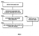
- Figure 5 is a process flow diagram for passive wire detection, according to one aspect of the present invention.
- FIG. 1B is a block diagram showing the internal functional architecture of computing system 100 that is used on a helicopter/aircraft or any other transport system that needs to detect stationery objects to avoid collisions/damage.
- Computing system 100 includes a processing unit 101 for executing computer-executable process steps and interfaces with a computer bus 106.
- a digital camera interface 108 is provided that allows system 100 to receive raw image data from a digital camera 100A ( Figure 1C ) or various digital cameras that are placed on a helicopter. Interface 108 receives the image data from the digital cameras and sends the raw data to processor 101.
- Component 102 is intended to represent plural input devices, such as a mouse and keyboard that allow a user to interact with system 100.
- output devices 109 represents one or more output devices, for example, a monitor, a printing device, a device that can generate an audible alarm to alert the pilot of the helicopter are included in output devices 109.
- Storage device 107 stores applications, executable code according to one aspect of the present. Some of these files are stored using an installation program. For example, processor 101 executes computer-executable process steps of an installation program so that it can properly execute the application program.
- Communication interface 105 allows system 100 to interface with other computing systems, networks and communication systems (not shown).
- Random access memory (“RAM”) 103 also interfaces to computer bus 106 to provide processor 101 with access to memory storage. When executing stored computer-executable process steps from storage device 107, processor 101 stores and executes the process steps out of RAM 103.
- ROM 104 Read only memory (“ROM”) 104 is provided to store invariant instruction sequences such as start-up instruction sequences or basic input/output operating system (BIOS).
- BIOS basic input/output operating system
- the Figure 1B architecture is intended to provide an example of an architecture that can be used to implement the executable process steps according to one aspect of the present invention. This architecture should not be viewed as a limitation. Other systems and architectures may be used to implement the executable code, described below. For example, a specialized application specific integrated circuit ("basic”) or a field programmable gate array (“FPGA”) may be used to implement the adaptive aspects of the present invention.
- basic application specific integrated circuit
- FPGA field programmable gate array
- Figure 1C shows a digital camera 100A that is placed in a helicopter to take images while the helicopter is flying. The images are sent to computing system 100 for processing and for detecting wires, in real time, as described below in detail. It is noteworthy that although one digital camera is shown in Figure 1C , it is only intended to illustrate the adaptive aspects of the present invention. The adaptive aspects of the present invention are not limited to any particular number/type of cameras.
- FIG. 2A shows a block diagram of a system according to one aspect of the present invention that passively detects wires.
- Input image 200 i.e. raw digital image data
- the pre-processor segment 201 removes non-wire like clutter from image data 200.
- Pre-processor 201 includes a ring median filter 202 and a wavelet de-noise module 203 that are used to initially filter the image. Ring median filter 202 and wavelet de-noise module 203 are described below in detail.
- Output 200B from pre-processor 201 is sent to a segment finder module 204 that determines the degree to which each pixel's surroundings are wire like.
- Segment finder 204 includes a gradient phase module 205, a vector kernel 207 and a threshold module 208 that are described below in detail.
- a linker module 209 receives output 200E from segment finder 204.
- the linker module 209 links various segments to build a wire like structure and based on that output 214, a wireless overlay is generated.
- Linker module 209 includes a radon-like morphological operator 210, a segment linker accumulator 211, threshold module 212 and spatial and temporal filter module 213 that are described below in detail.
- Preprocessor Module 201 The ring median filter 202 eliminates clutter but saves the wires for further analysis.
- Figure 2B shows an example of how a ring median filter 202 is applied.
- the pixel value for a pixel 202B is replaced by the median value of the dark pixels in image area 202A along the ring (shown as 202C). This eliminates objects with a scale size (length or width) less than % ring (202C) diameter. Subtracting this median image from the original image would leave objects with a scale size that is less than 1 ⁇ 2 of the ring diameter.
- Wires in an image may have low contrast or high contrast compared to the background clutter.
- the two examples are shown in Figure 2C with high/low background clutter.
- Ring median filter 202 is made large enough so that multiple closely spaced wires (as shown in Figure 2C ) are not eliminated.
- the ring median filtered image 200A is then processed by wavelet de-noise module 203.
- Wavelet de-noise module 203 eliminates 2-D wavelet coefficients that are uncorrelated across multiple length scales. Subtracting this filtered image from the original image 200, as shown in Figure 2A , leaves small-scale features of all contrasts (for example, single wires) and large-scale features with low contrast (for example, multiple wires) intact.
- a similar filter for example, the Susan Filter may be used to produce output 200B that retains single/multiple wires based on contrast and scale selection.
- Segment finder 204 is a prediction tool that identifies potential "wire candidates" based on output 200B.
- Output 200B is received by a gradient phase module 205.
- the gradient phase module 205 computes a vector along the local intensity gradient at all pixels in the image scene. For pixels on or very near a wire, this vector will be orthogonal to the wire. Each vector is normalized and, thus, is a unit phasor. This is shown in Figure 3 with the local intensity gradient of image 200B shown as 300.
- Output 200C from the gradient phase module 205 is sent to a vector kernel 207.
- Vector kernel 207 provides a kernel operator to segregate and identify wire candidates.
- Vector kernel 207 provides a kernel that is oriented over each pixel perpendicular to the gradient vector at that pixel. For pixels in the near vicinity of a wire, the kernel will lie along the length of the wire.
- the normalized two-dimensional vectors, or unit phasors, calculated by the gradient phase module 205 are weighted via the kernel and then summed.
- the kernel multipliers are positive on one side of the (hypothetical) wire and negative on the other side. If there is a wire, then it will orient the phasors on opposite sides in the same direction and hence the sum will be coherent.
- Figure 4 shows image samples after vector kernel 207 is applied to output 200C.
- Random white noise is shown as 401 and is not a wire candidate.
- 402 shows a uniform unidirectional intensity gradient, which is an edge and hence is not considered to be a wire candidate.
- 403 shows an example of a wire candidate where the 2-D vectors are oriented in opposite directions. 403 is considered to be a wire candidate because it is the only case where the vector kernel produces a strong output coherent with the phase of the central pixel.
- Output 200D from vector kernel 207 is sent to a threshold module 208.
- Threshold module 208 assigns a "1" to pixels with vector kernel outputs satisfying plural conditions, for example, if the magnitude exceeds a programmable threshold, and the absolute value of the phase difference (relative to the gradient phase of the central pixel) is below a programmable threshold. A "0" is assigned to all other pixels.
- the final output 200E of segment finder module 204 is a binary image.
- Output (binary image) 200E from segment finder module 204 is sent to linker module 209.
- Linker module 209 receives binary image (200E) and uses a radon-like morphological operator 210 to identify "1" pixels from the input image that are strongly aligned into wire like filaments.
- Operator 210 uses multiple linear morphological operators, and the structure elements of these operators have different orientations. Each of these morphological operators is centered over each of the "1" pixels in the segment finder output, and the number of segment finder "1" pixels within its structure element are summed. If the sum exceeds a programmable threshold, the identification number of that morphological operator is stored in a memory location associated with the central pixel.
- the final output 200F of morphological operator 210 is an array of morphological operator identification numbers, indexed by pixel.
- Output 200F from operator 210 is sent to a segment linker accumulator (or buffer) 211 that links various pixels into large-scale lines.
- Module 211 accumulates data in an empty linker accumulation image buffer. This image buffer is at least the same size as the segment finder binary image output 200E, so their pixels are in one-to-one correspondence.
- Module 211 centers each of the morphological operators in output 200F associated with this index over a corresponding pixel in the linker accumulation buffer (211). The value "1" is then added to each of the pixels in the linker accumulation buffer 211 that is overlaid by the structure element of the morphological operator.
- the final output 200G of the segment linker accumulator 211 is an image with large values along linear and curvilinear features, such as wires, but low (or zero) elsewhere.
- a threshold module 212 then applies preprogrammed thresholds to Output 200G from module 211. Every pixel in output 200G of the segment linker accumulator 211 with a value above the threshold is set equal to "1.” All other pixels are set equal to "0.” Thus, the output 200H of threshold module 212 is a binary image similar to that of segment finder module 204, except with non-wire like features removed and with gaps between aligned wire like features (partially) filled in.
- Output 200H from threshold module 212 is then filtered by using spatial and temporal filters 213.
- the spatial filter eliminates features in output 200H of threshold module 212 that do not have length/width ratios consistent with wires, and the temporal filter eliminates pixels that do not satisfy a minimum threshold for frame-to-frame persistence.
- the filtered output 214 is a binary wire overlay 214.
- the wire overlay 214 is used to determine whether wires have been detected, and the pilot is notified if they have. This notification may be performed by overlaying the wire overlay on the video display output, sounding an audible alarm, or any other means that calls the pilot's attention to the wires. This will allow the pilot to change course and avoid potential catastrophic accidents.
- Figure 5 shows a process flow diagram for passively detecting wires from a transport system (for example, a helicopter), according to one aspect of the present invention. This is based on real-time image processing.
- a raw digital image 200 is received from a digital camera(s) that is mounted on a helicopter (as shown in Figure 1C ).
- the image is received by a processing system, an example of which is shown in Figure 2A .
- step S502 the raw image is pre-processed so that non-wire like clutter (if present) in the input image 200 is reduced.
- Pre-processing module 201 is used to reduce the non-wire like clutter. As described above, pre-processing module 201 uses a ring median filter 202 and wavelet de-noise module 203 to reduce the non-wire like clutter.
- step S504 system 215 using segment finder 204 determines "wire-like" candidates. Segment finder 204 applies a gradient phase module 205 and a vector kernel 207 to determine the wire like candidates. A threshold module 208 is used to filter out non-wire like pixels from the output 200D from vector kernel 207.
- linker module 209 links the "wire like" pixel candidates to determine if a wire is actually present.
- Linker 209 uses radon-like morphological operator 210 and segment linker accumulator 211.
- Threshold module 212 applies programmable thresholds to the output 200G from segment linker accumulator 211 to filter out non wire like pixel structures.
- Output 200H is then filtered by using spatial and temporal filters 213 to produce a wire overlay 214.
- step S508 if a wire is detected (based on output 214), the pilot is notified. The pilot can then steer the helicopter away from the wires and avoid catastrophic accidents. It is noteworthy that the output 214 may be sent to a central computing system of the helicopter and can be used to automatically steer away the helicopter.
- wires can be detected real-time without using active sensors and hence, accidents can be avoided without comprising security.
Landscapes
- Engineering & Computer Science (AREA)
- Physics & Mathematics (AREA)
- General Physics & Mathematics (AREA)
- Theoretical Computer Science (AREA)
- Computer Vision & Pattern Recognition (AREA)
- Image Processing (AREA)
- Image Analysis (AREA)
Description
- The present invention relates to transport systems, and more particularly, to passive wire detection techniques.
- One of the leading causes of catastrophic inflight helicopter and tilt-rotor aircraft (or any other transportation system, used interchangeably throughout this specification) accidents is due to contact with static objects, for example, contact with wires ("wire-strike"). Such accidents typically occur when a helicopter collides with power lines, wires or communications lines. Many of these accidents result in fatalities, and they are especially a problem during low altitude helicopter cruising and maneuvering.
- Wires are oftentimes difficult to see by naked eye due to their small size, and this can be exasperated even further by bad weather and visual clutter.
Figure 1A illustrateshelicopter 10 flying towards wires 20 (power lines). If the pilot does not detect the power lines on time, thenhelicopter 10 can crash resulting in fatalities and loss of property. - Active wire sensors in helicopters could be used to mitigate this problem. An active sensor is a detection device that requires input energy from a source other than the target, which is being sensed. An example of an active sensor is a measuring instrument that generates a signal, transmits it to a target, and receives a reflected signal from the target. Information concerning the target is obtained by comparison of the received signal with the transmitted signal. Active sensors cannot be used in cases where stealth/secrecy is required, for example, military operations, and hence this is not a desirable solution for these applications.
- Another potential solution is to use passive sensors. Passive sensor devices detect without emitting any energy signals that can cause them to be detected. The detection occurs as a result of radiation from the target or reflection of ambient energy on the target.
- However, even with high resolution passive sensors, wires can be very difficult to see at minimum avoidance ranges because they are often sub-pixel, embedded in wire-like clutter, and/or have poor signal-to-noise ratio ("SNR").
- Solutions using passive sensors are disclosed in Nixon, M. D., Loveland, R. C., "Passive Detection of Sub-Pixel Obstacles for Flight Safety", Proc. SPIE, Vol. 4472, 2001, pages 1-10,
US 2002/0153485 A1 and Yamamoto K., Yamada K., "Analysis of the Infrared Images to Detect Power Lines", IEEE TENON, 1997, pages 343-346. - Another option is to use real-time image processing to detect the wires. However, conventional real time processing techniques rely on a host of convolution and filtering techniques. Low latency requirements coupled with standard real time processing constraints place severe limits on the size of the convolution kernels and filter sizes. This in turn, degrades wire detection performance and reliability.
Therefore, there is a need for a method and system for parallel real-time passive wire detection techniques, which can efficiently detect wires and notify the pilot of wires to minimize the risk of wire prone accidents. - According to the invention there is a method and system as defined in the appended claims.
In one aspect of the present invention, a method for passively detecting wires from a mobile transportation system is provided. The method includes pre-processing a digital image taken from a digital camera of the transportation system, wherein the pre-processing is performed by a pre-processing module to reduce non-wire like clutter from the digital image; identifying pixels that can be classified as wire like by using a segment finder module on the digital image that has been pre-processed by the pre-processing module; and linking the identified pixels to determine if a wire like structure is present, wherein a linker module links the pixels that can be classified as wire like, to generate a wire overlay.
In another aspect of the present invention, a system for passively detecting wires from a mobile transportation system is provided. The system includes a pre-processing module for pre-processing a digital image taken from a digital camera of the transport system, wherein the pre-processing module reduces non-wire like clutter from the digital image; a segment finder module for identifying pixels that can be classified as wire like; and a linker module for linking the identified pixels to determine if a wire like structure is present, wherein the linker module links pixels that can be classified as wire like, to generate a wire overlay. - This brief summary has been provided so that the nature of the invention may be understood quickly. A more complete understanding of the invention can be obtained by reference to the following detailed description of the preferred embodiments thereof in connection with the attached drawings.
- The foregoing features and other features of the present invention will now be described with reference to the drawings of a preferred embodiment. In the drawings, the same components have the same reference numerals. The illustrated embodiment is intended to illustrate, but not to limit the invention. The drawings include the following figures:
-
Figure 1A shows how a helicopter can face wire structures while the helicopter is in flight; -
Figure 1B is a block diagram of a computing system used for passive wire detection, according to one aspect of the present invention; -
Figure 1C shows a block diagram of a helicopter using a digital camera, according to one aspect of the present invention; -
Figure 2A shows a block diagram of the overall system architecture for passive wire detection, according to one aspect of the present invention; -
Figure 2B shows an example of using a ring median filter, according to one aspect of the present invention; -
Figure 2C shows an example of wires with background clutter, according to one aspect of the present invention; -
Figure 3 illustrates an image output after a gradient phase operator is applied; -
Figure 4 shows example of image outputs after a vector kernel operator is applied; and -
Figure 5 is a process flow diagram for passive wire detection, according to one aspect of the present invention. - To facilitate an understanding of the preferred embodiment, the general architecture and operation of a computing system will be described. The specific architecture and operation of the preferred embodiments will then be described with reference to the general architecture.
-
Figure 1B is a block diagram showing the internal functional architecture ofcomputing system 100 that is used on a helicopter/aircraft or any other transport system that needs to detect stationery objects to avoid collisions/damage.Computing system 100 includes aprocessing unit 101 for executing computer-executable process steps and interfaces with acomputer bus 106. - A
digital camera interface 108 is provided that allowssystem 100 to receive raw image data from adigital camera 100A (Figure 1C ) or various digital cameras that are placed on a helicopter.Interface 108 receives the image data from the digital cameras and sends the raw data toprocessor 101. -
Component 102 is intended to represent plural input devices, such as a mouse and keyboard that allow a user to interact withsystem 100. Similarly,output devices 109 represents one or more output devices, for example, a monitor, a printing device, a device that can generate an audible alarm to alert the pilot of the helicopter are included inoutput devices 109. -
Storage device 107 stores applications, executable code according to one aspect of the present. Some of these files are stored using an installation program. For example,processor 101 executes computer-executable process steps of an installation program so that it can properly execute the application program. -
Communication interface 105 allowssystem 100 to interface with other computing systems, networks and communication systems (not shown). - Random access memory ("RAM") 103 also interfaces to
computer bus 106 to provideprocessor 101 with access to memory storage. When executing stored computer-executable process steps fromstorage device 107,processor 101 stores and executes the process steps out ofRAM 103. - Read only memory ("ROM") 104 is provided to store invariant instruction sequences such as start-up instruction sequences or basic input/output operating system (BIOS).
- The
Figure 1B architecture is intended to provide an example of an architecture that can be used to implement the executable process steps according to one aspect of the present invention. This architecture should not be viewed as a limitation. Other systems and architectures may be used to implement the executable code, described below. For example, a specialized application specific integrated circuit ("basic") or a field programmable gate array ("FPGA") may be used to implement the adaptive aspects of the present invention. -
Figure 1C shows adigital camera 100A that is placed in a helicopter to take images while the helicopter is flying. The images are sent tocomputing system 100 for processing and for detecting wires, in real time, as described below in detail. It is noteworthy that although one digital camera is shown inFigure 1C , it is only intended to illustrate the adaptive aspects of the present invention. The adaptive aspects of the present invention are not limited to any particular number/type of cameras. -
Figure 2A shows a block diagram of a system according to one aspect of the present invention that passively detects wires. Input image 200 (i.e. raw digital image data) from digital camera (100A) is received by apre-processor segment 201. Thepre-processor segment 201 removes non-wire like clutter fromimage data 200.Pre-processor 201 includes a ring median filter 202 and awavelet de-noise module 203 that are used to initially filter the image. Ring median filter 202 andwavelet de-noise module 203 are described below in detail. -
Output 200B frompre-processor 201 is sent to asegment finder module 204 that determines the degree to which each pixel's surroundings are wire like.Segment finder 204 includes agradient phase module 205, avector kernel 207 and athreshold module 208 that are described below in detail. - A
linker module 209 receivesoutput 200E fromsegment finder 204. Thelinker module 209 links various segments to build a wire like structure and based on thatoutput 214, a wireless overlay is generated.Linker module 209 includes a radon-likemorphological operator 210, asegment linker accumulator 211,threshold module 212 and spatial andtemporal filter module 213 that are described below in detail. - Preprocessor Module 201: The ring median filter 202 eliminates clutter but saves the wires for further analysis.
Figure 2B shows an example of how a ring median filter 202 is applied. The pixel value for apixel 202B is replaced by the median value of the dark pixels inimage area 202A along the ring (shown as 202C). This eliminates objects with a scale size (length or width) less than % ring (202C) diameter. Subtracting this median image from the original image would leave objects with a scale size that is less than ½ of the ring diameter. - Wires in an image may have low contrast or high contrast compared to the background clutter. The two examples are shown in
Figure 2C with high/low background clutter. Ring median filter 202 is made large enough so that multiple closely spaced wires (as shown inFigure 2C ) are not eliminated. The ring median filtered image 200A is then processed bywavelet de-noise module 203. - Wavelet
de-noise module 203 eliminates 2-D wavelet coefficients that are uncorrelated across multiple length scales. Subtracting this filtered image from theoriginal image 200, as shown inFigure 2A , leaves small-scale features of all contrasts (for example, single wires) and large-scale features with low contrast (for example, multiple wires) intact. - It is noteworthy that instead of using
wavelet de-noise module 203, a similar filter (for example, the Susan Filter) may be used to produceoutput 200B that retains single/multiple wires based on contrast and scale selection. - Segment Finder 204:
Segment finder 204 is a prediction tool that identifies potential "wire candidates" based onoutput 200B.Output 200B is received by agradient phase module 205. Thegradient phase module 205 computes a vector along the local intensity gradient at all pixels in the image scene. For pixels on or very near a wire, this vector will be orthogonal to the wire. Each vector is normalized and, thus, is a unit phasor. This is shown inFigure 3 with the local intensity gradient ofimage 200B shown as 300. -
Output 200C from thegradient phase module 205 is sent to avector kernel 207.Vector kernel 207 provides a kernel operator to segregate and identify wire candidates. -
Vector kernel 207 provides a kernel that is oriented over each pixel perpendicular to the gradient vector at that pixel. For pixels in the near vicinity of a wire, the kernel will lie along the length of the wire. The normalized two-dimensional vectors, or unit phasors, calculated by thegradient phase module 205 are weighted via the kernel and then summed. The kernel multipliers are positive on one side of the (hypothetical) wire and negative on the other side. If there is a wire, then it will orient the phasors on opposite sides in the same direction and hence the sum will be coherent. The mathematical result is shown as following:
where Kn is the kernel multiplier for the nth nonzero kernel element (n = 1 for the central pixel), and θ n is the phase for that element.
For random phase fields, < ρ 1 2 > = N, and φ1 , is uncorrelated wi th θ 1 .
For perfectly aligned fields, < p1 2> = 0 (because the positive and negative Kn contributions cancel, and φ 1 = θ 1 (modulo π).
For a perfectly straight wire, < ρ 1 2 > = N2 , and φ 1 = θ 1 (modulo π). -
Figure 4 shows image samples aftervector kernel 207 is applied tooutput 200C. Random white noise is shown as 401 and is not a wire candidate. 402 shows a uniform unidirectional intensity gradient, which is an edge and hence is not considered to be a wire candidate. 403 shows an example of a wire candidate where the 2-D vectors are oriented in opposite directions. 403 is considered to be a wire candidate because it is the only case where the vector kernel produces a strong output coherent with the phase of the central pixel. -
Output 200D fromvector kernel 207 is sent to athreshold module 208.Threshold module 208 assigns a "1" to pixels with vector kernel outputs satisfying plural conditions, for example, if the magnitude exceeds a programmable threshold, and the absolute value of the phase difference (relative to the gradient phase of the central pixel) is below a programmable threshold. A "0" is assigned to all other pixels. Thus, thefinal output 200E ofsegment finder module 204 is a binary image. - Output (binary image) 200E from
segment finder module 204 is sent tolinker module 209.Linker module 209 receives binary image (200E) and uses a radon-likemorphological operator 210 to identify "1" pixels from the input image that are strongly aligned into wire like filaments.Operator 210 uses multiple linear morphological operators, and the structure elements of these operators have different orientations. Each of these morphological operators is centered over each of the "1" pixels in the segment finder output, and the number of segment finder "1" pixels within its structure element are summed. If the sum exceeds a programmable threshold, the identification number of that morphological operator is stored in a memory location associated with the central pixel. Thus, thefinal output 200F ofmorphological operator 210 is an array of morphological operator identification numbers, indexed by pixel. -
Output 200F fromoperator 210 is sent to a segment linker accumulator (or buffer) 211 that links various pixels into large-scale lines.Module 211 accumulates data in an empty linker accumulation image buffer. This image buffer is at least the same size as the segment finderbinary image output 200E, so their pixels are in one-to-one correspondence. For each pixel index in the operator inoutput 200F,Module 211 centers each of the morphological operators inoutput 200F associated with this index over a corresponding pixel in the linker accumulation buffer (211). The value "1" is then added to each of the pixels in thelinker accumulation buffer 211 that is overlaid by the structure element of the morphological operator. Since the structure elements are linear, accumulation buffer pixels along or in between linear and curvilinear features will have "1" added to them many times. Thus thefinal output 200G of thesegment linker accumulator 211 is an image with large values along linear and curvilinear features, such as wires, but low (or zero) elsewhere. - A
threshold module 212 then applies preprogrammed thresholds toOutput 200G frommodule 211. Every pixel inoutput 200G of thesegment linker accumulator 211 with a value above the threshold is set equal to "1." All other pixels are set equal to "0." Thus, theoutput 200H ofthreshold module 212 is a binary image similar to that ofsegment finder module 204, except with non-wire like features removed and with gaps between aligned wire like features (partially) filled in. -
Output 200H fromthreshold module 212 is then filtered by using spatial andtemporal filters 213. The spatial filter eliminates features inoutput 200H ofthreshold module 212 that do not have length/width ratios consistent with wires, and the temporal filter eliminates pixels that do not satisfy a minimum threshold for frame-to-frame persistence. The filteredoutput 214 is abinary wire overlay 214. - The
wire overlay 214 is used to determine whether wires have been detected, and the pilot is notified if they have. This notification may be performed by overlaying the wire overlay on the video display output, sounding an audible alarm, or any other means that calls the pilot's attention to the wires. This will allow the pilot to change course and avoid potential catastrophic accidents. -
Figure 5 shows a process flow diagram for passively detecting wires from a transport system (for example, a helicopter), according to one aspect of the present invention. This is based on real-time image processing. - Turning in detail to
Figure 5 , in step S500, a rawdigital image 200 is received from a digital camera(s) that is mounted on a helicopter (as shown inFigure 1C ). The image is received by a processing system, an example of which is shown inFigure 2A . - In step S502, the raw image is pre-processed so that non-wire like clutter (if present) in the
input image 200 is reduced.Pre-processing module 201 is used to reduce the non-wire like clutter. As described above,pre-processing module 201 uses a ring median filter 202 andwavelet de-noise module 203 to reduce the non-wire like clutter. - After the image is pre-processed, in step S504,
system 215 usingsegment finder 204 determines "wire-like" candidates.Segment finder 204 applies agradient phase module 205 and avector kernel 207 to determine the wire like candidates. Athreshold module 208 is used to filter out non-wire like pixels from theoutput 200D fromvector kernel 207. - In step S506,
linker module 209 links the "wire like" pixel candidates to determine if a wire is actually present.Linker 209 uses radon-likemorphological operator 210 andsegment linker accumulator 211.Threshold module 212 applies programmable thresholds to theoutput 200G fromsegment linker accumulator 211 to filter out non wire like pixel structures.Output 200H is then filtered by using spatial andtemporal filters 213 to produce awire overlay 214. - In step S508, if a wire is detected (based on output 214), the pilot is notified. The pilot can then steer the helicopter away from the wires and avoid catastrophic accidents. It is noteworthy that the
output 214 may be sent to a central computing system of the helicopter and can be used to automatically steer away the helicopter. - In one aspect, wires can be detected real-time without using active sensors and hence, accidents can be avoided without comprising security.
- It is noteworthy that the foregoing illustrations based on a helicopter contacting a stationery wires are not intended to be limiting. The real image processing techniques are intended to be used for any transport system that needs to avoid collision based on any objects that are difficult to detect.
- While the present invention is described above with respect to what is currently considered its preferred embodiments, it is to be understood that the invention is not limited to that described above. To the contrary, the invention is intended to cover various modifications and equivalent arrangements within the scope of the appended claims.
Claims (14)
- A method for passively detecting wires from a mobile transportation system, comprising:pre-processing a digital image taken from a digital camera of the transport system, wherein the pre-processing is performed by a pre-processing module (201) to reduce non-wire like clutter from the digital image;identifying pixels that can be classified as wire like by using a segment finder module (204) on the digital image that has been pre-processed by the pre-processing module; andlinking the pixels that can be classified as wire like to determine if a wire like structure is present, wherein a linker module (209) links the pixels that can be classified as wire like, to generate a wire overlay, the linker module comprising spatial and temporal filters, the spatial filter eliminating features which are not consistent with wires, and the temporal filter eliminating pixels that do not satisfy a minimum frame-to-frame persistence.
- The method of Claim 1, further comprising alerting a pilot of the transportation system if one or more wires is detected.
- The method of Claims 1 or 2, wherein the pre-processing module (201) applies a ring median filter (202) to eliminate clutter and retain portions of the digital image for further processing.
- The method of Claim 3, wherein the pre-processing module (201) includes a wavelet de-noise module (203) that receives an output from the ring median filter (202) and the digital image is then subtracted from the output of the wavelet de-noise module.
- The method of any preceding claim, wherein the segment finder module (204) includes a gradient phase module (207) that computes a vector along a local intensity gradient for plural image pixels in the digital image.
- The method of any preceding claim, wherein the segment finder module includes a vector kernel operator that uses a kernel oriented over each pixel perpendicular to a phase of a local intensity gradient, so that if there is a wire the kernel is placed along the wire.
- A system for passively detecting wires from a mobile transportation system, comprising:a pre-processing module (201) for pre-processing a digital image taken from a digital camera of the transport system, wherein the pre-processing module reduces non-wire like clutter from the digital image;a segment finder module (204) for identifying pixels that can be classified as wire like on the digital image that has been pre-processed by the pre-processing module; anda linker module (209) for linking the pixels that can be classified as wire like as to determine if a wire like structure is present, wherein the linker module links pixels that can be classified as wire like, to generate a wire overlay, the linker module comprising spatial and temporal filters, the spatial filter eliminating features which are not consistent with wires, and the temporal filter eliminating pixels that do not satisfy a minimum frame-to-frame persistence.
- The system of Claim 7, wherein the pre-processing module (201) applies a ring median filter (202) to eliminate clutter and retain portions of the digital image for further processing.
- The system of Claim 8, wherein the pre-processing module (201) includes a wavelet de-noise module (203) that receives an output from the ring median filter (202) and the digital image is then subtracted from the output of the wavelet de-noise module.
- The system of any of Claims 7-9, wherein the segment finder module (204) includes a gradient phase module (205) that computes a vector along a local intensity gradient for plural image pixels in the digital image.
- The system of any of Claims 7-10, wherein the segment finder module (204) includes a vector kernel operator that uses a kernel oriented over each pixel perpendicular to a phase of a local intensity gradient, so that if there is a wire the kernel is placed along the wire.
- The system of any of Claims 7-11, wherein the transport system is a helicopter.
- The system of any of Claims 7-12, wherein the transport system is an aircraft.
- The system of any of Claims 7-13, further comprising a specialized application specific integrated circuit ("ASIC") or a field programmable gate array ("FPGA").
Applications Claiming Priority (2)
| Application Number | Priority Date | Filing Date | Title |
|---|---|---|---|
| US11/184,472 US7512258B2 (en) | 2005-07-19 | 2005-07-19 | System and method for passive wire detection |
| PCT/US2006/019542 WO2007011450A1 (en) | 2005-07-19 | 2006-05-22 | System and method for passive wire detection |
Publications (2)
| Publication Number | Publication Date |
|---|---|
| EP1908010A1 EP1908010A1 (en) | 2008-04-09 |
| EP1908010B1 true EP1908010B1 (en) | 2013-12-25 |
Family
ID=37133492
Family Applications (1)
| Application Number | Title | Priority Date | Filing Date |
|---|---|---|---|
| EP06770712.5A Not-in-force EP1908010B1 (en) | 2005-07-19 | 2006-05-22 | System and method for passive wire detection |
Country Status (8)
| Country | Link |
|---|---|
| US (1) | US7512258B2 (en) |
| EP (1) | EP1908010B1 (en) |
| JP (1) | JP4960357B2 (en) |
| KR (1) | KR101257528B1 (en) |
| AU (1) | AU2006270506A1 (en) |
| CA (1) | CA2605977C (en) |
| IL (1) | IL187313A (en) |
| WO (1) | WO2007011450A1 (en) |
Cited By (1)
| Publication number | Priority date | Publication date | Assignee | Title |
|---|---|---|---|---|
| NO340705B1 (en) * | 2014-12-22 | 2017-06-06 | Kleon Prosjekt As | Method and apparatus for detecting an airspace from an aircraft |
Families Citing this family (8)
| Publication number | Priority date | Publication date | Assignee | Title |
|---|---|---|---|---|
| US8160382B2 (en) * | 2007-10-15 | 2012-04-17 | Lockheed Martin Corporation | Method of object recognition in image data using combined edge magnitude and edge direction analysis techniques |
| US20090208053A1 (en) * | 2008-02-19 | 2009-08-20 | Benjamin Kent | Automatic identification and removal of objects in an image, such as wires in a frame of video |
| US20120250010A1 (en) * | 2011-03-31 | 2012-10-04 | Richard Charles Hannay | Aerial Inspection System(s) and Method(s) |
| US9183516B2 (en) | 2013-07-25 | 2015-11-10 | The Boeing Company | Systems and methods for locating and prioritizing cargo |
| US9964658B2 (en) * | 2015-10-06 | 2018-05-08 | The United States Of America As Represented By The Secretary Of The Army | Method of autonomous power line detection, avoidance, navigation, and inspection using aerial crafts |
| CN105825619B (en) * | 2016-03-25 | 2018-09-18 | 南京第五十五所技术开发有限公司 | A kind of high-voltage line floating material alarm method based on image procossing |
| US10402646B2 (en) * | 2017-09-21 | 2019-09-03 | Amazon Technologies, Inc. | Object detection and avoidance for aerial vehicles |
| NO347027B1 (en) | 2021-06-02 | 2023-04-24 | Kleon Solutions As | Method and system for detecting a line above ground from a helicopter |
Family Cites Families (9)
| Publication number | Priority date | Publication date | Assignee | Title |
|---|---|---|---|---|
| US4970701A (en) * | 1971-03-22 | 1990-11-13 | The United States Of America As Represented By The Secretary Of The Navy | Wire detector |
| US5245588A (en) * | 1972-01-07 | 1993-09-14 | The United States Of America As Represented By The Secretary Of The Navy | Regenerative radio-frequency wire detector |
| US4685143A (en) * | 1985-03-21 | 1987-08-04 | Texas Instruments Incorporated | Method and apparatus for detecting edge spectral features |
| US4736439A (en) * | 1985-05-24 | 1988-04-05 | The United States Of America As Represented By The Secretary Of The Navy | Image preprocessing by modified median filter |
| US4742557A (en) * | 1985-11-08 | 1988-05-03 | Ncr Corporation | Adaptive character extraction method and system |
| JP2001344597A (en) * | 2000-05-30 | 2001-12-14 | Fuji Heavy Ind Ltd | Fusion vision device |
| US6940994B2 (en) * | 2001-03-09 | 2005-09-06 | The Boeing Company | Passive power line detection system for aircraft |
| US7286912B2 (en) * | 2001-12-10 | 2007-10-23 | Bae Systems Information And Electronic Systems Integration Inc. | Method and apparatus for avoidance of power lines or trip wires by fixed and rotary winged aircraft |
| US7466243B2 (en) * | 2005-10-13 | 2008-12-16 | The Boeing Company | System and method for passive wire detection |
-
2005
- 2005-07-19 US US11/184,472 patent/US7512258B2/en not_active Expired - Fee Related
-
2006
- 2006-05-22 AU AU2006270506A patent/AU2006270506A1/en not_active Abandoned
- 2006-05-22 CA CA2605977A patent/CA2605977C/en not_active Expired - Fee Related
- 2006-05-22 KR KR1020077027404A patent/KR101257528B1/en not_active Expired - Fee Related
- 2006-05-22 EP EP06770712.5A patent/EP1908010B1/en not_active Not-in-force
- 2006-05-22 WO PCT/US2006/019542 patent/WO2007011450A1/en not_active Ceased
- 2006-05-22 JP JP2008522774A patent/JP4960357B2/en active Active
-
2007
- 2007-11-12 IL IL187313A patent/IL187313A/en not_active IP Right Cessation
Cited By (2)
| Publication number | Priority date | Publication date | Assignee | Title |
|---|---|---|---|---|
| NO340705B1 (en) * | 2014-12-22 | 2017-06-06 | Kleon Prosjekt As | Method and apparatus for detecting an airspace from an aircraft |
| US10372986B2 (en) | 2014-12-22 | 2019-08-06 | Kleon Prosjekt As | Method and device for detecting an overhead cable from an aerial vessel |
Also Published As
| Publication number | Publication date |
|---|---|
| WO2007011450A1 (en) | 2007-01-25 |
| AU2006270506A1 (en) | 2007-01-25 |
| US7512258B2 (en) | 2009-03-31 |
| KR20080026536A (en) | 2008-03-25 |
| IL187313A (en) | 2011-08-31 |
| EP1908010A1 (en) | 2008-04-09 |
| JP2009501677A (en) | 2009-01-22 |
| CA2605977C (en) | 2015-08-11 |
| KR101257528B1 (en) | 2013-04-23 |
| CA2605977A1 (en) | 2007-01-25 |
| US20070019838A1 (en) | 2007-01-25 |
| JP4960357B2 (en) | 2012-06-27 |
| IL187313A0 (en) | 2008-04-13 |
Similar Documents
| Publication | Publication Date | Title |
|---|---|---|
| IL187313A (en) | System and method for passive wire detection | |
| AU2004269298B2 (en) | Target detection improvements using temporal integrations and spatial fusion | |
| WO2018125014A1 (en) | A method for foreign object debris detection | |
| EP4363877B1 (en) | Methods and systems for detecting vessels | |
| Marques et al. | An algorithm for the detection of vessels in aerial images | |
| US11209517B2 (en) | Mobile body detection device, mobile body detection method, and mobile body detection program | |
| Kim | Double layered-background removal filter for detecting small infrared targets in heterogenous backgrounds | |
| KR102456190B1 (en) | Black box system for offshore fishing vessels | |
| Havens et al. | Improved detection and false alarm rejection using FLGPR and color imagery in a forward-looking system | |
| Luesutthiviboon et al. | Bio-inspired enhancement for optical detection of drones using convolutional neural networks | |
| US12403936B2 (en) | Method for controlling a driver assistance system during operation of a vehicle | |
| AU2012216436B2 (en) | System and method for passive wire detection | |
| US20230022429A1 (en) | Systems and methods for efficently sensing collison threats | |
| Havens et al. | Sensor-fused detection of explosive hazards | |
| Havens et al. | Narrow-band processing and fusion approach for explosive hazard detection in FLGPR | |
| Petković et al. | Target detection for visual collision avoidance system | |
| US7466243B2 (en) | System and method for passive wire detection | |
| Kolluri et al. | Ship detection from satellite images with advanced deep learning model (Single Shot Detector (SSD)) | |
| Priyadharshini et al. | Lightweight Edge AI Model for Real-Time Vessel Detection in Maritime Surveillance Using Multi-Modal Data | |
| Ieracitano et al. | Towards an explainable artificial intelligence approach for ships detection from satellite imagery | |
| Allard et al. | Ship detection and characterization using polarimetric SAR data | |
| Gupta et al. | Optimized Activation Function-Based SAR Ship Detection | |
| JP2012225868A (en) | Instruction support device | |
| Syed et al. | AI Blinks, Chaos Winks: Adversarial Vulnerability of Object Detection in High-Density Urban Mobility Scenarios | |
| Wang et al. | Robust Small Object Detection on Water Surfaces via Multi-Scale Contextual Attention and Channel-Normalized Feature Aggregation |
Legal Events
| Date | Code | Title | Description |
|---|---|---|---|
| PUAI | Public reference made under article 153(3) epc to a published international application that has entered the european phase |
Free format text: ORIGINAL CODE: 0009012 |
|
| 17P | Request for examination filed |
Effective date: 20080206 |
|
| AK | Designated contracting states |
Kind code of ref document: A1 Designated state(s): AT BE BG CH CY CZ DE DK EE ES FI FR GB GR HU IE IS IT LI LT LU LV MC NL PL PT RO SE SI SK TR |
|
| 17Q | First examination report despatched |
Effective date: 20111121 |
|
| DAX | Request for extension of the european patent (deleted) | ||
| REG | Reference to a national code |
Ref country code: DE Ref legal event code: R079 Ref document number: 602006039794 Country of ref document: DE Free format text: PREVIOUS MAIN CLASS: G06T0005000000 Ipc: G06T0007000000 |
|
| GRAP | Despatch of communication of intention to grant a patent |
Free format text: ORIGINAL CODE: EPIDOSNIGR1 |
|
| RIC1 | Information provided on ipc code assigned before grant |
Ipc: G06T 7/00 20060101AFI20130206BHEP |
|
| GRAP | Despatch of communication of intention to grant a patent |
Free format text: ORIGINAL CODE: EPIDOSNIGR1 |
|
| INTG | Intention to grant announced |
Effective date: 20130712 |
|
| GRAS | Grant fee paid |
Free format text: ORIGINAL CODE: EPIDOSNIGR3 |
|
| GRAA | (expected) grant |
Free format text: ORIGINAL CODE: 0009210 |
|
| AK | Designated contracting states |
Kind code of ref document: B1 Designated state(s): AT BE BG CH CY CZ DE DK EE ES FI FR GB GR HU IE IS IT LI LT LU LV MC NL PL PT RO SE SI SK TR |
|
| REG | Reference to a national code |
Ref country code: GB Ref legal event code: FG4D |
|
| REG | Reference to a national code |
Ref country code: CH Ref legal event code: EP |
|
| REG | Reference to a national code |
Ref country code: AT Ref legal event code: REF Ref document number: 646948 Country of ref document: AT Kind code of ref document: T Effective date: 20140115 |
|
| REG | Reference to a national code |
Ref country code: IE Ref legal event code: FG4D |
|
| REG | Reference to a national code |
Ref country code: DE Ref legal event code: R096 Ref document number: 602006039794 Country of ref document: DE Effective date: 20140213 |
|
| PG25 | Lapsed in a contracting state [announced via postgrant information from national office to epo] |
Ref country code: FI Free format text: LAPSE BECAUSE OF FAILURE TO SUBMIT A TRANSLATION OF THE DESCRIPTION OR TO PAY THE FEE WITHIN THE PRESCRIBED TIME-LIMIT Effective date: 20131225 Ref country code: SE Free format text: LAPSE BECAUSE OF FAILURE TO SUBMIT A TRANSLATION OF THE DESCRIPTION OR TO PAY THE FEE WITHIN THE PRESCRIBED TIME-LIMIT Effective date: 20131225 Ref country code: LT Free format text: LAPSE BECAUSE OF FAILURE TO SUBMIT A TRANSLATION OF THE DESCRIPTION OR TO PAY THE FEE WITHIN THE PRESCRIBED TIME-LIMIT Effective date: 20131225 |
|
| REG | Reference to a national code |
Ref country code: NL Ref legal event code: VDEP Effective date: 20131225 |
|
| REG | Reference to a national code |
Ref country code: AT Ref legal event code: MK05 Ref document number: 646948 Country of ref document: AT Kind code of ref document: T Effective date: 20131225 |
|
| REG | Reference to a national code |
Ref country code: LT Ref legal event code: MG4D |
|
| PG25 | Lapsed in a contracting state [announced via postgrant information from national office to epo] |
Ref country code: LV Free format text: LAPSE BECAUSE OF FAILURE TO SUBMIT A TRANSLATION OF THE DESCRIPTION OR TO PAY THE FEE WITHIN THE PRESCRIBED TIME-LIMIT Effective date: 20131225 |
|
| PG25 | Lapsed in a contracting state [announced via postgrant information from national office to epo] |
Ref country code: EE Free format text: LAPSE BECAUSE OF FAILURE TO SUBMIT A TRANSLATION OF THE DESCRIPTION OR TO PAY THE FEE WITHIN THE PRESCRIBED TIME-LIMIT Effective date: 20131225 Ref country code: BE Free format text: LAPSE BECAUSE OF FAILURE TO SUBMIT A TRANSLATION OF THE DESCRIPTION OR TO PAY THE FEE WITHIN THE PRESCRIBED TIME-LIMIT Effective date: 20131225 Ref country code: IS Free format text: LAPSE BECAUSE OF FAILURE TO SUBMIT A TRANSLATION OF THE DESCRIPTION OR TO PAY THE FEE WITHIN THE PRESCRIBED TIME-LIMIT Effective date: 20140425 |
|
| PG25 | Lapsed in a contracting state [announced via postgrant information from national office to epo] |
Ref country code: NL Free format text: LAPSE BECAUSE OF FAILURE TO SUBMIT A TRANSLATION OF THE DESCRIPTION OR TO PAY THE FEE WITHIN THE PRESCRIBED TIME-LIMIT Effective date: 20131225 Ref country code: RO Free format text: LAPSE BECAUSE OF FAILURE TO SUBMIT A TRANSLATION OF THE DESCRIPTION OR TO PAY THE FEE WITHIN THE PRESCRIBED TIME-LIMIT Effective date: 20131225 Ref country code: PT Free format text: LAPSE BECAUSE OF FAILURE TO SUBMIT A TRANSLATION OF THE DESCRIPTION OR TO PAY THE FEE WITHIN THE PRESCRIBED TIME-LIMIT Effective date: 20140428 Ref country code: ES Free format text: LAPSE BECAUSE OF FAILURE TO SUBMIT A TRANSLATION OF THE DESCRIPTION OR TO PAY THE FEE WITHIN THE PRESCRIBED TIME-LIMIT Effective date: 20131225 Ref country code: AT Free format text: LAPSE BECAUSE OF FAILURE TO SUBMIT A TRANSLATION OF THE DESCRIPTION OR TO PAY THE FEE WITHIN THE PRESCRIBED TIME-LIMIT Effective date: 20131225 Ref country code: CZ Free format text: LAPSE BECAUSE OF FAILURE TO SUBMIT A TRANSLATION OF THE DESCRIPTION OR TO PAY THE FEE WITHIN THE PRESCRIBED TIME-LIMIT Effective date: 20131225 Ref country code: PL Free format text: LAPSE BECAUSE OF FAILURE TO SUBMIT A TRANSLATION OF THE DESCRIPTION OR TO PAY THE FEE WITHIN THE PRESCRIBED TIME-LIMIT Effective date: 20131225 Ref country code: SK Free format text: LAPSE BECAUSE OF FAILURE TO SUBMIT A TRANSLATION OF THE DESCRIPTION OR TO PAY THE FEE WITHIN THE PRESCRIBED TIME-LIMIT Effective date: 20131225 Ref country code: CY Free format text: LAPSE BECAUSE OF FAILURE TO SUBMIT A TRANSLATION OF THE DESCRIPTION OR TO PAY THE FEE WITHIN THE PRESCRIBED TIME-LIMIT Effective date: 20131225 |
|
| REG | Reference to a national code |
Ref country code: DE Ref legal event code: R097 Ref document number: 602006039794 Country of ref document: DE |
|
| PG25 | Lapsed in a contracting state [announced via postgrant information from national office to epo] |
Ref country code: DK Free format text: LAPSE BECAUSE OF FAILURE TO SUBMIT A TRANSLATION OF THE DESCRIPTION OR TO PAY THE FEE WITHIN THE PRESCRIBED TIME-LIMIT Effective date: 20131225 |
|
| PLBE | No opposition filed within time limit |
Free format text: ORIGINAL CODE: 0009261 |
|
| STAA | Information on the status of an ep patent application or granted ep patent |
Free format text: STATUS: NO OPPOSITION FILED WITHIN TIME LIMIT |
|
| 26N | No opposition filed |
Effective date: 20140926 |
|
| PG25 | Lapsed in a contracting state [announced via postgrant information from national office to epo] |
Ref country code: LU Free format text: LAPSE BECAUSE OF FAILURE TO SUBMIT A TRANSLATION OF THE DESCRIPTION OR TO PAY THE FEE WITHIN THE PRESCRIBED TIME-LIMIT Effective date: 20140522 |
|
| REG | Reference to a national code |
Ref country code: CH Ref legal event code: PL |
|
| REG | Reference to a national code |
Ref country code: DE Ref legal event code: R097 Ref document number: 602006039794 Country of ref document: DE Effective date: 20140926 |
|
| PG25 | Lapsed in a contracting state [announced via postgrant information from national office to epo] |
Ref country code: CH Free format text: LAPSE BECAUSE OF NON-PAYMENT OF DUE FEES Effective date: 20140531 Ref country code: MC Free format text: LAPSE BECAUSE OF FAILURE TO SUBMIT A TRANSLATION OF THE DESCRIPTION OR TO PAY THE FEE WITHIN THE PRESCRIBED TIME-LIMIT Effective date: 20131225 Ref country code: LI Free format text: LAPSE BECAUSE OF NON-PAYMENT OF DUE FEES Effective date: 20140531 |
|
| REG | Reference to a national code |
Ref country code: IE Ref legal event code: MM4A |
|
| PG25 | Lapsed in a contracting state [announced via postgrant information from national office to epo] |
Ref country code: IE Free format text: LAPSE BECAUSE OF NON-PAYMENT OF DUE FEES Effective date: 20140522 |
|
| PG25 | Lapsed in a contracting state [announced via postgrant information from national office to epo] |
Ref country code: SI Free format text: LAPSE BECAUSE OF FAILURE TO SUBMIT A TRANSLATION OF THE DESCRIPTION OR TO PAY THE FEE WITHIN THE PRESCRIBED TIME-LIMIT Effective date: 20131225 |
|
| REG | Reference to a national code |
Ref country code: FR Ref legal event code: PLFP Year of fee payment: 11 |
|
| PG25 | Lapsed in a contracting state [announced via postgrant information from national office to epo] |
Ref country code: BG Free format text: LAPSE BECAUSE OF FAILURE TO SUBMIT A TRANSLATION OF THE DESCRIPTION OR TO PAY THE FEE WITHIN THE PRESCRIBED TIME-LIMIT Effective date: 20131225 |
|
| PG25 | Lapsed in a contracting state [announced via postgrant information from national office to epo] |
Ref country code: IT Free format text: LAPSE BECAUSE OF FAILURE TO SUBMIT A TRANSLATION OF THE DESCRIPTION OR TO PAY THE FEE WITHIN THE PRESCRIBED TIME-LIMIT Effective date: 20131225 Ref country code: GR Free format text: LAPSE BECAUSE OF FAILURE TO SUBMIT A TRANSLATION OF THE DESCRIPTION OR TO PAY THE FEE WITHIN THE PRESCRIBED TIME-LIMIT Effective date: 20140326 |
|
| PG25 | Lapsed in a contracting state [announced via postgrant information from national office to epo] |
Ref country code: TR Free format text: LAPSE BECAUSE OF FAILURE TO SUBMIT A TRANSLATION OF THE DESCRIPTION OR TO PAY THE FEE WITHIN THE PRESCRIBED TIME-LIMIT Effective date: 20131225 Ref country code: HU Free format text: LAPSE BECAUSE OF FAILURE TO SUBMIT A TRANSLATION OF THE DESCRIPTION OR TO PAY THE FEE WITHIN THE PRESCRIBED TIME-LIMIT; INVALID AB INITIO Effective date: 20060522 |
|
| REG | Reference to a national code |
Ref country code: FR Ref legal event code: PLFP Year of fee payment: 12 |
|
| REG | Reference to a national code |
Ref country code: FR Ref legal event code: PLFP Year of fee payment: 13 |
|
| PGFP | Annual fee paid to national office [announced via postgrant information from national office to epo] |
Ref country code: DE Payment date: 20190530 Year of fee payment: 14 |
|
| PGFP | Annual fee paid to national office [announced via postgrant information from national office to epo] |
Ref country code: FR Payment date: 20190527 Year of fee payment: 14 |
|
| PGFP | Annual fee paid to national office [announced via postgrant information from national office to epo] |
Ref country code: GB Payment date: 20190528 Year of fee payment: 14 |
|
| REG | Reference to a national code |
Ref country code: DE Ref legal event code: R119 Ref document number: 602006039794 Country of ref document: DE |
|
| GBPC | Gb: european patent ceased through non-payment of renewal fee |
Effective date: 20200522 |
|
| PG25 | Lapsed in a contracting state [announced via postgrant information from national office to epo] |
Ref country code: GB Free format text: LAPSE BECAUSE OF NON-PAYMENT OF DUE FEES Effective date: 20200522 Ref country code: FR Free format text: LAPSE BECAUSE OF NON-PAYMENT OF DUE FEES Effective date: 20200531 |
|
| PG25 | Lapsed in a contracting state [announced via postgrant information from national office to epo] |
Ref country code: DE Free format text: LAPSE BECAUSE OF NON-PAYMENT OF DUE FEES Effective date: 20201201 |