EP1907803B9 - Messvorrichtung und leitfähigkeitsmessvorrichtung für die bestimmung von durchflussmengen elektrisch leitender flüssigkeiten, messelement und verfahren - Google Patents
Messvorrichtung und leitfähigkeitsmessvorrichtung für die bestimmung von durchflussmengen elektrisch leitender flüssigkeiten, messelement und verfahren Download PDFInfo
- Publication number
- EP1907803B9 EP1907803B9 EP06762797A EP06762797A EP1907803B9 EP 1907803 B9 EP1907803 B9 EP 1907803B9 EP 06762797 A EP06762797 A EP 06762797A EP 06762797 A EP06762797 A EP 06762797A EP 1907803 B9 EP1907803 B9 EP 1907803B9
- Authority
- EP
- European Patent Office
- Prior art keywords
- measurement
- electrode
- electrodes
- container
- conductivity
- Prior art date
- Legal status (The legal status is an assumption and is not a legal conclusion. Google has not performed a legal analysis and makes no representation as to the accuracy of the status listed.)
- Not-in-force
Links
- 238000000034 method Methods 0.000 title claims abstract description 10
- 239000007788 liquid Substances 0.000 title abstract description 85
- 230000001419 dependent effect Effects 0.000 claims abstract description 7
- 238000005259 measurement Methods 0.000 claims description 65
- 238000011156 evaluation Methods 0.000 claims description 23
- XLYOFNOQVPJJNP-UHFFFAOYSA-N water Substances O XLYOFNOQVPJJNP-UHFFFAOYSA-N 0.000 claims description 20
- 230000005684 electric field Effects 0.000 claims description 13
- 239000012530 fluid Substances 0.000 claims description 9
- 229920003023 plastic Polymers 0.000 claims description 9
- 239000004033 plastic Substances 0.000 claims description 9
- 239000000463 material Substances 0.000 claims description 5
- 239000004020 conductor Substances 0.000 claims description 4
- 230000007423 decrease Effects 0.000 claims description 3
- 239000002184 metal Substances 0.000 claims description 3
- 229910001092 metal group alloy Inorganic materials 0.000 claims description 2
- 238000001746 injection moulding Methods 0.000 claims 1
- 230000008859 change Effects 0.000 description 14
- 238000013461 design Methods 0.000 description 5
- 230000002093 peripheral effect Effects 0.000 description 5
- 239000006187 pill Substances 0.000 description 4
- TZCXTZWJZNENPQ-UHFFFAOYSA-L barium sulfate Chemical compound [Ba+2].[O-]S([O-])(=O)=O TZCXTZWJZNENPQ-UHFFFAOYSA-L 0.000 description 3
- 230000008901 benefit Effects 0.000 description 3
- 230000003247 decreasing effect Effects 0.000 description 3
- 238000010586 diagram Methods 0.000 description 3
- 239000007772 electrode material Substances 0.000 description 3
- 238000001914 filtration Methods 0.000 description 3
- 238000009434 installation Methods 0.000 description 3
- 230000015572 biosynthetic process Effects 0.000 description 2
- 230000004048 modification Effects 0.000 description 2
- 238000012986 modification Methods 0.000 description 2
- 101100298225 Caenorhabditis elegans pot-2 gene Proteins 0.000 description 1
- OKTJSMMVPCPJKN-UHFFFAOYSA-N Carbon Chemical compound [C] OKTJSMMVPCPJKN-UHFFFAOYSA-N 0.000 description 1
- 241000792859 Enema Species 0.000 description 1
- 238000010276 construction Methods 0.000 description 1
- 230000000694 effects Effects 0.000 description 1
- 239000007920 enema Substances 0.000 description 1
- 229940095399 enema Drugs 0.000 description 1
- 229910002804 graphite Inorganic materials 0.000 description 1
- 239000010439 graphite Substances 0.000 description 1
- 238000004519 manufacturing process Methods 0.000 description 1
- 239000011159 matrix material Substances 0.000 description 1
- 239000012811 non-conductive material Substances 0.000 description 1
- 230000008569 process Effects 0.000 description 1
- 230000000630 rising effect Effects 0.000 description 1
- 229910052710 silicon Inorganic materials 0.000 description 1
- 239000010703 silicon Substances 0.000 description 1
- 230000002123 temporal effect Effects 0.000 description 1
Images

Classifications
-
- G—PHYSICS
- G01—MEASURING; TESTING
- G01F—MEASURING VOLUME, VOLUME FLOW, MASS FLOW OR LIQUID LEVEL; METERING BY VOLUME
- G01F13/00—Apparatus for measuring by volume and delivering fluids or fluent solid materials, not provided for in the preceding groups
-
- G—PHYSICS
- G01—MEASURING; TESTING
- G01F—MEASURING VOLUME, VOLUME FLOW, MASS FLOW OR LIQUID LEVEL; METERING BY VOLUME
- G01F13/00—Apparatus for measuring by volume and delivering fluids or fluent solid materials, not provided for in the preceding groups
- G01F13/006—Apparatus for measuring by volume and delivering fluids or fluent solid materials, not provided for in the preceding groups measuring volume in function of time
-
- G—PHYSICS
- G01—MEASURING; TESTING
- G01F—MEASURING VOLUME, VOLUME FLOW, MASS FLOW OR LIQUID LEVEL; METERING BY VOLUME
- G01F23/00—Indicating or measuring liquid level or level of fluent solid material, e.g. indicating in terms of volume or indicating by means of an alarm
- G01F23/22—Indicating or measuring liquid level or level of fluent solid material, e.g. indicating in terms of volume or indicating by means of an alarm by measuring physical variables, other than linear dimensions, pressure or weight, dependent on the level to be measured, e.g. by difference of heat transfer of steam or water
- G01F23/24—Indicating or measuring liquid level or level of fluent solid material, e.g. indicating in terms of volume or indicating by means of an alarm by measuring physical variables, other than linear dimensions, pressure or weight, dependent on the level to be measured, e.g. by difference of heat transfer of steam or water by measuring variations of resistance of resistors due to contact with conductor fluid
- G01F23/241—Indicating or measuring liquid level or level of fluent solid material, e.g. indicating in terms of volume or indicating by means of an alarm by measuring physical variables, other than linear dimensions, pressure or weight, dependent on the level to be measured, e.g. by difference of heat transfer of steam or water by measuring variations of resistance of resistors due to contact with conductor fluid for discrete levels
- G01F23/242—Mounting arrangements for electrodes
-
- G—PHYSICS
- G01—MEASURING; TESTING
- G01F—MEASURING VOLUME, VOLUME FLOW, MASS FLOW OR LIQUID LEVEL; METERING BY VOLUME
- G01F23/00—Indicating or measuring liquid level or level of fluent solid material, e.g. indicating in terms of volume or indicating by means of an alarm
- G01F23/22—Indicating or measuring liquid level or level of fluent solid material, e.g. indicating in terms of volume or indicating by means of an alarm by measuring physical variables, other than linear dimensions, pressure or weight, dependent on the level to be measured, e.g. by difference of heat transfer of steam or water
- G01F23/24—Indicating or measuring liquid level or level of fluent solid material, e.g. indicating in terms of volume or indicating by means of an alarm by measuring physical variables, other than linear dimensions, pressure or weight, dependent on the level to be measured, e.g. by difference of heat transfer of steam or water by measuring variations of resistance of resistors due to contact with conductor fluid
- G01F23/241—Indicating or measuring liquid level or level of fluent solid material, e.g. indicating in terms of volume or indicating by means of an alarm by measuring physical variables, other than linear dimensions, pressure or weight, dependent on the level to be measured, e.g. by difference of heat transfer of steam or water by measuring variations of resistance of resistors due to contact with conductor fluid for discrete levels
- G01F23/243—Schematic arrangements of probes combined with measuring circuits
-
- C—CHEMISTRY; METALLURGY
- C02—TREATMENT OF WATER, WASTE WATER, SEWAGE, OR SLUDGE
- C02F—TREATMENT OF WATER, WASTE WATER, SEWAGE, OR SLUDGE
- C02F2209/00—Controlling or monitoring parameters in water treatment
- C02F2209/05—Conductivity or salinity
-
- C—CHEMISTRY; METALLURGY
- C02—TREATMENT OF WATER, WASTE WATER, SEWAGE, OR SLUDGE
- C02F—TREATMENT OF WATER, WASTE WATER, SEWAGE, OR SLUDGE
- C02F2209/00—Controlling or monitoring parameters in water treatment
- C02F2209/40—Liquid flow rate
-
- C—CHEMISTRY; METALLURGY
- C02—TREATMENT OF WATER, WASTE WATER, SEWAGE, OR SLUDGE
- C02F—TREATMENT OF WATER, WASTE WATER, SEWAGE, OR SLUDGE
- C02F2307/00—Location of water treatment or water treatment device
- C02F2307/04—Location of water treatment or water treatment device as part of a pitcher or jug
Definitions
- level heights are carried out wherever liquid volumes or changes in the liquid volumes are to be determined.
- the measurement of the filling levels is usually carried out by means of electrodes which are partially immersed in the liquid.
- a suitable measuring arrangement the resistance or the electrical conductivity of the liquid is measured, the u. a. is proportional to the level height or the liquid volume.
- LF ⁇ 0 ⁇ ZK ⁇ V
- LF the electrical conductivity
- ⁇ 0 the specific conductivity of the liquid
- V the volume of the liquid
- ZK the so-called cell constant, which is the ratio of the electrode spacing and of the wetted electrode area.
- a liquid level indicator in particular for planters known, comprising an elongated rod with at least two mutually insulated electrodes and an electronic Circuit connected to the electrodes via extending in the rod conductor and fed by a DC voltage source.
- a display device indicates the liquid level.
- This level indicator requires several electrodes, which are arranged at different heights. Each electrode has its own conductor connected to the electronic circuit. This requires a correspondingly high installation costs.
- the DE 40 42 257 describes a method and an apparatus for determining the level and level heights of electrically conductive liquids.
- a resistor chain is used, which dips vertically into the liquid. From the measurement of the resistance of the overall arrangement it is possible to determine how many resistances lie above the liquid level. Or, which means the depth of the liquid level, since the metal surfaces are mounted along the level at a close and constant distance. This arrangement is complex and provides only discrete values of the level.
- a level electrode device which also has individual level electrodes, which are arranged on a carrier in the carrier longitudinal direction continuously displaceable.
- an electrode arrangement with a plurality of electrodes is known with which the electrical resistance of the liquid for determining the fill level is measured.
- a measuring electrode for determining the liquid level which has a conical or hemispherical configuration.
- the small diameter of the electrode is at the lower portion and the large diameter of the electrode is at the upper end.
- Level measurements are carried out in particular in water filter devices, the level measurements are used to determine the exhaustion of the filter means of the filter cartridge.
- Such an exhaustion indicator is for example from the EP 1 484 097 A1 known.
- This fatigue indicator is based on resistance measurements of the liquid with two electrodes, which are arranged one above the other in the water tank or which are located in the inlet channel. This device has the disadvantage that with changing water quality calibration measurements are required.
- a fatigue indicator using a plurality of electrodes immersed in the liquid.
- an evaluation unit for determining the detected filling volumes over a certain period of time is arranged, which in turn is connected to a display unit, the so-called fatigue indicator.
- raw water is introduced into the feed hopper, which runs down through the filter cartridge and is collected in a lower chamber as filtered water. Due to the alternating inlet and outlet of the raw water, the level changes many times during the life of a filter cartridge, so that it can be concluded from these level changes on the amount of liquid flowed through the filter cartridge. On the basis of the amount of liquid is made on the exhaustion indication of the exhaustion of the filter medium.
- the EP 1 125 748 A1 describes a printer cartridge that is provided with a level measuring device.
- the printer cartridge There are two electrodes, by means of which the level height is measured, the measured values are evaluated by means of a correlation and a coefficient table.
- GB 1,288,177 describes a level measuring device having three electrodes. Of these, the third, middle collector electrode is arranged obliquely, so that the distance between the collector electrode and the reference electrode changes in the vertical direction.
- the collector may be plate-shaped and have a logarithmic measuring function.
- the object of the invention is therefore to provide a measuring device which is simple in construction and makes the calibration measurements regarding the specific conductivity of the liquid superfluous. It is also an object to provide a simply constructed and manageable measuring element and a measuring method.
- b M is a number ⁇ 0 and ⁇ 1
- the evaluation device is designed at least for quotient formation of the measured values and for logarithmizing the quotients.
- the z-direction is selected perpendicular to the liquid level in the liquid container.
- the exponent can have a positive or negative sign.
- the invention is based on the recognition that for the determination of flow rates of electrically conductive liquids through a container neither the value of the conductivity of the liquid must be known nor the absolute value of the height of the liquid level must be determined, if an exponential relationship by the structural design of the measuring device between the measured value M t i (V (z)) and the volume V (z) of the liquid in the container.
- f P l (I describes the running index, ie f P 1 , f P 2 etc.) is understood to mean a design parameter that has a functional dependence on V (z) and thus on z.
- parameters P l are, depending on z, the shape of the container, the shape of the electrodes, the distance between the electrodes and properties of the electrode material.
- the distance of the electrodes may be the spatial distance of the two electrodes or else the distance relevant for the electric field lines. In the latter case, the two electrodes can lie directly next to one another, if an obstacle is arranged between the electrodes, which changes the path length of the electric field lines.
- At least one element is arranged between the two electrodes, which changes the path of the electric field lines forming between the two electrodes.
- This element can be a component of the carrier element on which the two electrodes are arranged or an additional element which is arranged on the carrier element.
- the element has a shape, so that the distance of the field lines changes exponentially with increasing value z.
- the element has a shape, so that the distance of the electric field lines decreases with increasing value z.
- the element is a plate whose free front edge has a curved course.
- the two electrodes can be arranged side by side on the carrier element, wherein the plate is arranged between the two electrodes.
- the electrodes are arranged on opposite sides on the carrier element and laterally adjacent to each electrode, such a plate is arranged, which changes the distance of the field lines between the electrodes.
- the plate can be arranged perpendicular to the carrier element.
- the orientation of these obstacle plates depends on the configuration of the carrier element and the arrangement of the electrodes on the carrier element. It is therefore also preferred that, when the electrodes are disposed opposite one another on a carrier element, the plates can be arranged parallel to the carrier element.
- At least one parameter function f P l must have an exponential dependence in order to become independent both of the knowledge of the conductivity of the liquid and of the knowledge of the absolute filling level.
- the underlying b P l is to be chosen such that small changes in volume of the liquid are also noticeable in a significant change in the measured values.
- the choice of the underlying b P l also depends on in which unit z is measured. All figures always refer to z measured in cm, even if this is not explicitly mentioned below. Accordingly, areas in cm 2 and volume in cm 3 are to be considered.
- b P l in the range of 0 ⁇ b P l ⁇ 5, in particular 1 ⁇ b P l ⁇ 1.5 to choose with b P l ⁇ 1.
- the parameter P l is the area A of at least one electrode.
- a (V (z)) is the wetted with the liquid conductive electrode surface, which varies with increasing or decreasing volume according to their structural design.
- a (V (z)) f P l ( V ( z )) ⁇ b A 1 V ( z ) .
- the remaining parameter functions such. B. the parameter function that the Container shape describes, have a linear relationship.
- the liquid container may be a cylinder, cube or cuboid.
- b F in the range less than 2.5.
- b F is therefore the largest to choose, for. B. largest 2.5.
- the electrode area may have a linear dependence on z, i.
- the electrodes may have a constant width over their entire extension in the z-direction.
- the parameter functions with respect to the filling volume determining container shape F (V (z)) and / or the surface of the Electrode A (V (z)) and / or other parameter functions e.g. B. have a linear relationship.
- An exponential dependence can also have the material of the electrodes by the material properties such.
- the measuring element has a carrier element, wherein the two electrodes are arranged on opposite sides of the carrier element.
- the carrier element may be, for example, a carrier plate.
- the electrodes are already positioned in the production of the measuring element, whereby the installation of the measuring element in the liquid container simplified wind. An adjustment of the two electrodes for setting a predetermined size of the measuring cell is eliminated.
- the measuring element is arranged in the liquid container such that the broad second electrode end is located at the top.
- the broad second electrode end is located at the top.
- the measuring element may be integrated in the wall of the liquid container.
- the liquid container is an inlet funnel of a water filter device.
- the liquid is usually supplied from above.
- the drain opening is located in the bottom wall of the inlet funnel, where a filter element, for. B. a filter cartridge is arranged.
- the Determination of the flow rate can be used in accordance with a particular use of the measuring device for determining the time for the replacement of the filter cartridge and in that respect as a volume load measuring device for filter cartridges.
- the evaluation device can be connected to a display unit.
- This display unit when using the measuring device as a volume load measuring device for filter cartridges, may be a display unit which indicates to the user the replacement timing for the filter cartridge.
- At least the voltage source, the evaluation device and the at least one measuring element are integrated in one structural unit.
- the display unit can also be integrated into the structural unit.
- the evaluation device and the at least one measuring element are preferably combined in one structural unit.
- the measuring element according to the invention for the determination of a fill level-dependent measured value of electrically conductive liquids with at least one elongate electrode provides that the area A of the electrode increases exponentially with increasing distance z from the first electrode end to the second electrode end.
- a (V (z)) ⁇ b A 1 V ( z ) where A z ⁇ ⁇ O z B z ⁇ dz with B (z) width of the electrode as a function of z. It follows that also for B (z) there is an exponential relation A (V (z)) ⁇ A (z) ⁇ B (z) ⁇ b A 2 for example
- b A 2 preferably 0 ⁇ b A 2 ⁇ 5 and b A 2 ⁇ 1, with a preferred range for b A 2 the range between 1 and 1.5 (1 ⁇ b A 2 ⁇ 1.5).
- the width of the electrode may also change in stages, the envelope of the stages having the described exponential relationship. This embodiment leads to corresponding jumps in the measuring curve, which can be used for determining the absolute filling level heights with appropriate design of the connected to the measuring element evaluation.
- the width B 1 at the first electrode end is preferably 0.1 mm to 20 mm.
- the width B 2 at the second end of the electrode is preferably 5 mm to 30 mm.
- a beam-like electrode section extending perpendicularly to the electrode axis is arranged. This bar-type broadening serves to provide a defined initial measured value.
- a contact element is provided at one of the two electrode ends.
- the contact element is preferably attached to the upper electrode end, which protrudes from the liquid.
- the electrodes may consist of a metal, a metal alloy, an electrically conductive plastic or other electrically conductive material.
- At least one electrode is arranged on a carrier element.
- the measuring element can also be integrated in the wall of a liquid container.
- the wall of the liquid container forms the carrier element.
- the carrier element represents an independent component
- the shape of a plate is preferred, on the two opposite sides of each electrode can be arranged.
- the electric field between both electrodes extends around the support element.
- both electrodes are identical.
- the support plate preferably has a double-T cross-section, which has the advantage of high stability and thus prevents damage to the electrode under mechanical stress of the measuring element.
- the support plate preferably has adjacent to the first end of the electrode two feet, which serve to establish a defined distance from the bottom of the liquid container. Thereby an initial electric field is formed, which extends under the measuring element. At low liquid levels in the container, the initial field is still completely inside the liquid column.
- both the electrodes and the support plate made of plastic.
- an electrically conductive plastic for the electrodes and a non-conductive plastic for the carrier plate selected.
- the measuring element can be manufactured inexpensively in this way as a two-component injection-molded part.
- the measurement for determining the basis b M for the respective system is usually carried out once with predetermined amounts of liquid, before the determination of the measured values begins.
- the value of the base b M is thus determined once and then used as a basis for the calculation of the measured values.
- the value b M is used when logarithmizing the quotient in the determination of dV i .
- the measured values M t i determined at intervals of 1 to 100 sec.
- Which temporal intervals are expedient results inter alia also from the frequency of use and from the pressure flow velocity of the respective device.
- the device in question is a water filter device, it depends heavily on, among other things, how much filtered water the user requires.
- Preferred time intervals are 1 to 20 seconds, especially 2 to 10 seconds.
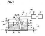
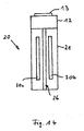
- the measuring device 10 comprises a conductivity measuring device 10 a, which has a measuring element 20, which is arranged in the interior of a liquid container 5.
- the liquid container 5 has a peripheral wall 6a and a bottom wall 6b, wherein in the upper region of the peripheral wall 6a a liquid inlet 7a and in the lower region a liquid outlet 7b is arranged. Both the supplied and the discharged amount of liquid change over time, so that the liquid level 40 of the liquid 41 in the container 5 also constantly changes (see double arrow).
- the measuring device 10 is provided for measuring the amount of liquid flowing through the container 5.
- the measuring element 20 of the measuring device 10 has a carrier plate 21, which has an electrode 30a, 30b at the front and rear side.
- care must be taken that, when the container is completely filled, neither the electrodes are completely immersed nor the electrical connections in the first place.
- the maximum permissible fluid level is marked 42.
- the non-illustrated electrode 30b on the back of the measuring element is identical. These are electrodes 30a, 30b whose width increases from bottom to top, the width of the electrode obeying an exponential function as a function of the distance z from the bottom or first electrode end 31.
- a (V (z)) and z are first over A (V (z)) ⁇ b A 1 V ( z ) , resulting in exponential broadening of the electrodes, namely A (V (z)) ⁇ b A 2 z or width B (z) ⁇ b A 2 for example
- the z-axis is in the right part of the FIG. 1 shown, wherein the zero point of the z-axis at the lower end 31 of the electrodes 30a, 30b is located.
- the distance of the lower end of the electrode 30a, 30b to the bottom wall 6 is marked with a.
- the Fluid volume in this area is taken into account in the evaluation by a fixed amount.
- the two electrodes 30a, 30b are connected via a connecting line 11 to an evaluation device 12, which is connected to a display unit 13.
- the components of the conductivity measuring device are expediently all combined in one structural unit, in particular accommodated or arranged in a single housing, as shown by way of example in FIG. 14 is shown.
- the container 5 can thus be equipped in a simple manner.
- the conductivity measuring device 10a is merely inserted into the container, which facilitates assembly.
- a conductivity measurement is carried out on the liquid 41, wherein the measurement and evaluation can be continuous or discontinuous.
- the electric field lines between the two electrodes 30a and 30b are indicated by reference numeral 36.
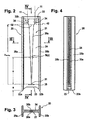
- the measuring element 20 consists of a carrier plate 21 and two measuring electrodes 30a, b.
- the support plate 21 itself consists of a middle plate 24 and two T-legs 25a, b arranged on the edge, as shown in FIG FIG. 3 you can see.
- the support plate 21 receives in cross section the shape of a double T.
- the middle plate 24 has a recess 23, wherein the T-legs are extended down and feet 22a, b form.
- each electrode 30a, b On the two sides of the middle plate 24 identical electrodes 30a, b are arranged, which are symmetrical except for a widening at the upper end.
- Each electrode 30a, b has a narrow first electrode end 31 and a wide second electrode end 32, wherein the first electrode end 31 is arranged at the bottom and the second electrode end 32 denotes the region of the maximum permissible liquid level 42.
- the width B of the electrode 30a increases continuously as the distance z from the first electrode end 31 to the second electrode end 32 increases.
- Z max denotes the distance from the lower first electrode end 31 to the upper electrode end 32.
- B (z) is proportional to b A 2 for example
- the electrode 30a has a beam-like widening 35 perpendicular to its longitudinal axis. This bar-type distribution 35 serves to define the size of the start measurement value. This also applies to the electrode 30b.
- the second electrode end 32 is adjoined by a contact element 33, on which a contact pill 34, for example of silicon, with graphite is applied.
- the contact element 33 is adapted to the size of the contact pill 34 and extends laterally beyond the electrode.
- the contact pill 34 serves as a connection element for the electrical connection line 11, which leads to the evaluation device 12, as shown in the FIG. 1 is shown.
- FIG. 3 is a section along the line III-III through the in FIG. 2 shown measuring element 20 shown. It can be seen that electrodes 30a, b are arranged on both sides of the middle plate 24.
- FIG. 4 is a vertical section along the line IV-IV through the in FIG. 2 shown measuring element shown.
- the support plate 21 is made of non-conductive plastic, while the electrodes 30 a, b of conductive Plastic are made. It is thereby possible to produce the measuring element 20 as a two-component injection-molded part.
- FIG. 5a a further embodiment of the measuring element 20 is shown, which differs from the embodiment according to FIG. 2 differs in that the electrodes 30a, 30b (30b on the back, therefore not visible) are designed asymmetrically and have a straight and an exponential, ie curved boundary line.
- FIG. 5b There is shown another modification showing a stepped electrode 30a.
- the envelope 37 of the individual stages 38 corresponds to the right-hand boundary line of the electrode 30a in FIG FIG. 5a and also shows an exponential course.
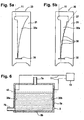
- FIG. 6 a further embodiment of the measuring device 10 is shown, which differs from the in FIG. 1 differs in that the electrodes 30a, 30b in the wall 6a of the liquid container 5 are arranged opposite and that the liquid inlet 7a is not arranged in the peripheral wall but in the top wall.
- the peripheral wall 6a assumes in this embodiment, the function of the support plate 21 according to the embodiments described above.
- the maximum permissible liquid level 42 is chosen such that the contact element 33 of the electrodes with the terminals is not immersed.
- FIG. 7 a further embodiment of the measuring device 10 is shown. While according to the embodiment of the FIG. 1 the liquid container 5 has a cuboid shape, so that the function F (V (z)) obeys a straight line, the liquid container 5 tapers according to FIG FIG. 7 up.
- the sidewall 6a is exponentially curved so that the function F (z), which is the cross-section of the liquid container 5, obeys an exponential function.
- F (V (z)) ⁇ F (z) ⁇ b F -z .
- the measuring element 20 can be equipped with electrodes 30a, 30b, which have a constant width in the z-direction.
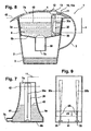
- a water filter device 1 is shown in vertical section, which has a can 2 with handle 3 and cover 4 and a chute 2 located in the inlet funnel 5a.
- a filter cartridge 50 is inserted in the outlet 7b of the inlet funnel 5a.
- the raw water 8 is filled after removal of the lid 4 or through the inlet opening 7a in the lid 4 in the inlet funnel 5a and flows from there through the filter cartridge 50 into the pot 2, at the bottom of which the filtered water 9 collects.
- the conductivity measuring device 10a is arranged, which has a measuring element 20 which is connected via an electrical line 11 to an evaluation device 12.
- the evaluation device 12 also includes the power supply unit.
- a display unit 13 is mounted, which are arranged in the lid 4 and visible from the outside.
- the conductivity measuring device 10a can also be designed as a structural unit, as shown in FIG FIG. 14 is shown. This assembly can be used for example in the lid or in the container.
- the liquid level 40 rises. During filtration, the liquid level 40 drops.
- This volume is a measure of the replacement time of the filter cartridge 50.
- the changes in the liquid level 40 are detected by the measuring element 20.
- the evaluation device 12 calculates the associated volume from the measured values, taking into account the dimensions of the inlet funnel 5a. If a predetermined volume value for the relevant filter cartridge 50 is exceeded, this is communicated to the user via the display unit 13.
- the measuring device 10 is used in this embodiment as a volume load measuring device for the filter cartridge 50.
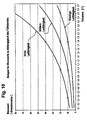
- FIG. 9 is a schematic diagram of the arrangement of the electrodes 30a, b shown.
- dV denotes the change in volume of the liquid when the liquid level 40 changes.
- the base b M must be determined for the respective measurement arrangement by a one-time calibration and enters the measurement as a constant base number. Thus, the determination of the difference volume is unique.
- the exponential measuring principle is very well suited.
- the advantage is that factors such. B. the absolute conductivity of the liquid does not affect the measurement and that only two measurements for a differential volume are necessary.
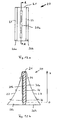
- FIGS 11 a and 11 b show two side views of a measuring element 20 according to a further embodiment.
- the two strip-shaped electrodes 30a, 30b which have a constant width, are arranged next to one another on a carrier plate 21.
- an obstacle in the form of a plate 26 is arranged, which consists of electrically non-conductive material and which shortens the path length of the electric field lines 36 with increasing z.
- the obstacle provides the same effect as a correspondingly varying distance between opposing electrodes.
- the plate 26 has a width B a (z) decreasing from the bottom to the top, with the result that the path length of the field lines 36 to the two electrodes 30 a, 30 b decreases from bottom to top.
- the two electrodes are arranged spatially adjacent to the carrier plate 21, the plate generates an exponentially decreasing distance D of the two electrodes 30a, 30b from bottom to top for the distance of the electric field lines.
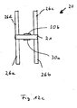
- FIGS. 12a to c a modification of this embodiment is shown, wherein the FIG. 12b the section along the line AA in FIG. 12a shows.
- the two electrodes 30 a, 30 b are arranged on opposite sides of the carrier plate 21.
- the electrodes 30a, 30b plates 26a, b, c and d are arranged on both sides.
- the functional relationship between the distance of the two electrodes 30a, 30b, which is relevant for the field lines, is analogous to the functional relationship which is associated with FIG Figures 11a and 11b is described.
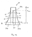
- FIG. 13 a further embodiment is shown in which the two electrodes 30a, b are arranged on opposite sides of the support plate 21.
- the two plates 26a, b which shorten the path of the electric field line 36 with increasing z, are arranged in the plane of the carrier element 21 and can also be part of the carrier plate 21:
- FIG. 14 shows the embodiment of the measuring element according to FIG. 11a with integrated evaluation device 12 and measuring device 13, which also includes the power source.
- the assembly is placed in a container and fastened there.
Landscapes
- Physics & Mathematics (AREA)
- Fluid Mechanics (AREA)
- General Physics & Mathematics (AREA)
- Thermal Sciences (AREA)
- Investigating Or Analyzing Materials By The Use Of Electric Means (AREA)
- Measurement Of Levels Of Liquids Or Fluent Solid Materials (AREA)
- Measuring Volume Flow (AREA)
- Measurement Of Resistance Or Impedance (AREA)
Priority Applications (1)
| Application Number | Priority Date | Filing Date | Title |
|---|---|---|---|
| PL06762797T PL1907803T3 (pl) | 2005-07-27 | 2006-07-25 | Urządzenie pomiarowe i urządzenie do pomiaru przewodności do wyznaczania przepływu elektrycznie przewodzących płynów, element pomiarowy i sposób |
Applications Claiming Priority (2)
| Application Number | Priority Date | Filing Date | Title |
|---|---|---|---|
| DE102005035045A DE102005035045B9 (de) | 2005-07-27 | 2005-07-27 | Messvorrichtung für die Bestimmung von Durchflussmengen elektrisch leitender Flüssigkeiten, Messelement und Verfahren |
| PCT/EP2006/007306 WO2007012455A1 (de) | 2005-07-27 | 2006-07-25 | Messvorrichtung und leitfähigkeitsmessvorrichtung für die bestimmung von durchflussmengen elektrisch leitender flüssigkeiten, messelement und verfahren |
Publications (3)
| Publication Number | Publication Date |
|---|---|
| EP1907803A1 EP1907803A1 (de) | 2008-04-09 |
| EP1907803B1 EP1907803B1 (de) | 2009-10-28 |
| EP1907803B9 true EP1907803B9 (de) | 2010-06-23 |
Family
ID=37440740
Family Applications (1)
| Application Number | Title | Priority Date | Filing Date |
|---|---|---|---|
| EP06762797A Not-in-force EP1907803B9 (de) | 2005-07-27 | 2006-07-25 | Messvorrichtung und leitfähigkeitsmessvorrichtung für die bestimmung von durchflussmengen elektrisch leitender flüssigkeiten, messelement und verfahren |
Country Status (13)
| Country | Link |
|---|---|
| US (1) | US7905144B2 (cg-RX-API-DMAC7.html) |
| EP (1) | EP1907803B9 (cg-RX-API-DMAC7.html) |
| JP (1) | JP4976390B2 (cg-RX-API-DMAC7.html) |
| CN (1) | CN100590396C (cg-RX-API-DMAC7.html) |
| AT (1) | ATE447163T1 (cg-RX-API-DMAC7.html) |
| AU (1) | AU2006274188A1 (cg-RX-API-DMAC7.html) |
| CA (1) | CA2614933A1 (cg-RX-API-DMAC7.html) |
| DE (2) | DE102005035045B9 (cg-RX-API-DMAC7.html) |
| ES (1) | ES2333906T3 (cg-RX-API-DMAC7.html) |
| IL (1) | IL188976A0 (cg-RX-API-DMAC7.html) |
| PL (1) | PL1907803T3 (cg-RX-API-DMAC7.html) |
| RU (1) | RU2381460C2 (cg-RX-API-DMAC7.html) |
| WO (1) | WO2007012455A1 (cg-RX-API-DMAC7.html) |
Families Citing this family (26)
| Publication number | Priority date | Publication date | Assignee | Title |
|---|---|---|---|---|
| DE102007034158B9 (de) | 2007-07-21 | 2013-01-24 | Brita Gmbh | Vorrichtung zur indirekten Messung der Erschöpfung des Filtermittels eines Filters |
| US8146420B2 (en) * | 2007-12-21 | 2012-04-03 | Boston Scientific Scimed, Inc. | HTA fluid level and fluid type measurement |
| DE102008054479A1 (de) * | 2008-12-10 | 2010-06-17 | Brita Gmbh | Leitfähigkeitsmessvorrichtung und Flüssigkeitsbehandlungsvorrichtung |
| US8171802B2 (en) | 2008-03-28 | 2012-05-08 | Brita Gmbh | Method for measuring the volume flow of electrically conductive liquids through a vessel |
| CA130799S (en) | 2008-12-10 | 2010-12-07 | Brita Gmbh | Water filter meter |
| CN101545799B (zh) * | 2009-04-24 | 2012-05-23 | 江苏工业学院 | 一种用于液位和电导率同时检测的非接触传感器 |
| DE102011075118B4 (de) | 2011-05-03 | 2023-12-07 | BSH Hausgeräte GmbH | Filtereinrichtung zum Reinigen von Wasser |
| AT513452B1 (de) * | 2012-10-05 | 2014-08-15 | Ait Austrian Inst Technology | Abgabevorrichtung für Medikamente |
| US9618116B2 (en) | 2013-08-27 | 2017-04-11 | Illinois Tool Works Inc. | Ported piston for automatic nailer |
| KR102073011B1 (ko) * | 2013-12-18 | 2020-03-02 | 삼성전자주식회사 | 오일 검출 장치, 그를 가지는 압축기 및 압축기의 제어 방법 |
| DE102014223945A1 (de) * | 2014-11-25 | 2016-05-25 | Volkswagen Aktiengesellschaft | Traktionsbatterie eines Elektrofahrzeugs umfassend ein Flüssigkeitsdetektionssystem und Verfahren zum Erkennen einer Standhöhe einer Flüssigkeit in der Traktionsbatterie |
| DE102015203744A1 (de) * | 2015-03-03 | 2016-09-08 | BSH Hausgeräte GmbH | Wasserführendes Haushaltsgerät mit Füllstandserfassung |
| DE102016205811A1 (de) * | 2015-08-21 | 2017-02-23 | Mahle International Gmbh | Wasserstandsensoreinrichtung eines Kraftstofffilters |
| RU2654316C2 (ru) * | 2015-11-30 | 2018-05-17 | Федеральное государственное бюджетное научное учреждение "Институт природно-технических систем" (ИПТС) | Устройство для измерения удельной электропроводности жидких сред |
| RU2658498C2 (ru) * | 2016-03-15 | 2018-06-21 | Федеральное государственное бюджетное научное учреждение "Институт природно-технических систем" (ИПТС) | Устройство для измерения удельной электропроводности жидких сред |
| DE102017111393A1 (de) | 2017-05-24 | 2018-11-29 | Endress+Hauser SE+Co. KG | Verfahren zur Prozessüberwachung |
| DE102017223853A1 (de) * | 2017-12-28 | 2019-07-04 | Kautex Textron Gmbh & Co. Kg | Verfahren zum Bestimmen einer Qulitätseigenschaft einer Betriebsflüssigkeit in einem Betriebsflüssigkeitsbehälter für ein Kraftfahrzeug und Betriebsflüssigkeitsbehälter zum Durchführen des Verfahrens |
| EP3514223A1 (de) * | 2018-01-17 | 2019-07-24 | Eppendorf AG | Multisensor für einen bioreaktor, bioreaktor, verfahren zur herstellung eines multisensors und zur messung von parametern |
| DE102018203633A1 (de) * | 2018-03-09 | 2019-09-12 | Kautex Textron Gmbh & Co. Kg | Betriebsflüssigkeitsbehälter mit kapazitiver Erfassung von Füllständen |
| RU2676797C1 (ru) * | 2018-03-19 | 2019-01-11 | Евгений Николаевич Коптяев | Компенсированный датчик уровня электролита |
| PT116029A (pt) * | 2019-12-27 | 2021-06-28 | Bosch Termotecnologia Sa | Sensor de condutividade e método para o funcionamento de um sensor de condutividade |
| US10969262B1 (en) * | 2020-08-18 | 2021-04-06 | Larq, Inc. | Filtering container with time-based capacitive flow monitoring |
| US11112763B1 (en) | 2020-08-18 | 2021-09-07 | Larq, Inc. | Monitoring and performance management system for a network of smart filtering containers |
| JP7560868B2 (ja) * | 2021-01-26 | 2024-10-03 | 国立研究開発法人農業・食品産業技術総合研究機構 | 地下水位変動の検知方法 |
| US12202740B2 (en) | 2022-03-02 | 2025-01-21 | Brita, LP | Container assembly |
| CN116106633B (zh) * | 2023-04-14 | 2023-07-18 | 南方电网科学研究院有限责任公司 | 液体电导率的确定方法、装置及存储介质 |
Family Cites Families (22)
| Publication number | Priority date | Publication date | Assignee | Title |
|---|---|---|---|---|
| DE1798256A1 (de) * | 1968-09-17 | 1972-01-20 | Schmitz Ludwig Dipl Ing | Verfahren und Vorrichtung zur linearen Durchflussmessung von Fluessigkeiten in druckfreien Fliessgerinnen und Messquerschnitten,insbesondere von Wasser und Abwasser |
| US3678749A (en) * | 1970-02-25 | 1972-07-25 | Patrick D Harper | Floatless fluid level gauge |
| JPS5757299Y2 (cg-RX-API-DMAC7.html) * | 1976-06-10 | 1982-12-09 | ||
| DE3018718C2 (de) * | 1980-05-16 | 1983-09-08 | Elba-Füllstandsgeräte GmbH, 6149 Rimbach | Füllstandselektroden-Vorrichtung |
| EP0152644A3 (en) * | 1983-12-01 | 1988-06-29 | Richard Mulder | Gauge for measuring the level or the conductance of a liquid present between two electrodes. |
| BR8503704A (pt) * | 1984-08-09 | 1986-05-06 | Tlv Co Ltd | Debitometro para medir o debito de um liquido |
| DE4042257A1 (de) * | 1990-12-31 | 1992-07-02 | Rudolf Rammner | Verfahren und vorrichtung zur ermittlung von fuellstand und pegelhoehen von elektrisch leitenden fluessigkeiten unter verwendung diskreter sensorpositionen |
| US5328597A (en) * | 1992-07-27 | 1994-07-12 | The Clorox Corporation | Electronic monitoring unit for monitoring number of uses of cartridge |
| US5437184A (en) * | 1993-10-27 | 1995-08-01 | Kdi/Triangle Electronics, Inc. | Capacitive liquid level sensor having phase detecting circuitry |
| JPH0850047A (ja) * | 1994-08-04 | 1996-02-20 | Hitachi Building Syst Eng & Service Co Ltd | 水位計測方法 |
| US5682184A (en) * | 1995-12-18 | 1997-10-28 | Xerox Corporation | System for sensing ink level and type of ink for an ink jet printer |
| JPH10119312A (ja) * | 1996-09-02 | 1998-05-12 | Brother Ind Ltd | インクカートリッジ及びインクジェット記録装置 |
| DE19726044C2 (de) * | 1997-06-19 | 1999-06-10 | Effem Gmbh | Flüssigkeitsstandanzeiger |
| FR2765331B1 (fr) * | 1997-06-27 | 1999-10-01 | Canon Kk | Procede et dispositif de determination des quantites de produits consommables contenus dans des reservoirs regroupes les uns a cote des autres et dispositif d'impression de documents mettant en oeuvre ce procede |
| US6431670B1 (en) * | 2000-02-14 | 2002-08-13 | Hewlett-Packard Company | Ink level sensing method and apparatus |
| DE10015764A1 (de) * | 2000-03-30 | 2001-10-11 | Brita Gmbh | Vorrichtung zum Messen des Volumens einer elektrisch leitenden Flüssigkeit |
| CN2421628Y (zh) * | 2000-04-17 | 2001-02-28 | 赵建设 | 电极式液位检测仪 |
| JP2003291367A (ja) * | 2002-04-02 | 2003-10-14 | Sony Corp | 液体残量表示装置 |
| JP2004077439A (ja) * | 2002-08-22 | 2004-03-11 | Tsurumi Mfg Co Ltd | 水位検出用電極 |
| CN2583640Y (zh) * | 2002-10-29 | 2003-10-29 | 武汉大学 | 体积法电子流量计 |
| ITPD20030121A1 (it) * | 2003-06-04 | 2004-12-05 | Laica Srl Ora Laica S P A | Metodo di determinazione delle condizioni di esaurimento di |
| US7487677B2 (en) * | 2004-04-19 | 2009-02-10 | Fook Tin Technologies Ltd. | Apparatus and methods for monitoring water consumption and filter usage |
-
2005
- 2005-07-27 DE DE102005035045A patent/DE102005035045B9/de not_active Expired - Fee Related
-
2006
- 2006-07-25 CN CN200680027566A patent/CN100590396C/zh not_active Expired - Fee Related
- 2006-07-25 EP EP06762797A patent/EP1907803B9/de not_active Not-in-force
- 2006-07-25 CA CA002614933A patent/CA2614933A1/en not_active Abandoned
- 2006-07-25 AT AT06762797T patent/ATE447163T1/de active
- 2006-07-25 PL PL06762797T patent/PL1907803T3/pl unknown
- 2006-07-25 US US11/989,273 patent/US7905144B2/en active Active
- 2006-07-25 AU AU2006274188A patent/AU2006274188A1/en not_active Abandoned
- 2006-07-25 DE DE502006005259T patent/DE502006005259D1/de active Active
- 2006-07-25 RU RU2008107344/28A patent/RU2381460C2/ru active
- 2006-07-25 ES ES06762797T patent/ES2333906T3/es active Active
- 2006-07-25 JP JP2008523214A patent/JP4976390B2/ja not_active Expired - Fee Related
- 2006-07-25 WO PCT/EP2006/007306 patent/WO2007012455A1/de not_active Ceased
-
2008
- 2008-01-23 IL IL188976A patent/IL188976A0/en unknown
Also Published As
| Publication number | Publication date |
|---|---|
| US7905144B2 (en) | 2011-03-15 |
| PL1907803T3 (pl) | 2010-03-31 |
| DE502006005259D1 (de) | 2009-12-10 |
| ATE447163T1 (de) | 2009-11-15 |
| DE102005035045A1 (de) | 2007-02-08 |
| ES2333906T3 (es) | 2010-03-02 |
| JP4976390B2 (ja) | 2012-07-18 |
| WO2007012455A1 (de) | 2007-02-01 |
| AU2006274188A1 (en) | 2007-02-01 |
| DE102005035045B9 (de) | 2007-11-08 |
| CN100590396C (zh) | 2010-02-17 |
| CA2614933A1 (en) | 2007-02-01 |
| EP1907803B1 (de) | 2009-10-28 |
| CN101233391A (zh) | 2008-07-30 |
| DE102005035045B4 (de) | 2007-05-16 |
| IL188976A0 (en) | 2008-08-07 |
| JP2009503464A (ja) | 2009-01-29 |
| US20090146670A1 (en) | 2009-06-11 |
| RU2381460C2 (ru) | 2010-02-10 |
| RU2008107344A (ru) | 2009-09-10 |
| EP1907803A1 (de) | 2008-04-09 |
Similar Documents
| Publication | Publication Date | Title |
|---|---|---|
| EP1907803B9 (de) | Messvorrichtung und leitfähigkeitsmessvorrichtung für die bestimmung von durchflussmengen elektrisch leitender flüssigkeiten, messelement und verfahren | |
| EP1348108A1 (de) | Verfahren und vorrichtung zum messen von pegelständen | |
| DE3213303C2 (de) | Meßvorrichtung zur Bestimmung der Kapazität eines in eine Flüssigkeit teilweise eingetauchten Kondensators | |
| DE3785185T2 (de) | Geraet und verfahren zum messen der stroemungscharakteristika einer petroleumstroemung. | |
| EP2373958A1 (de) | Leitfähigkeitsmessvorrichtung und flüssigkeitsbehandlungsvorrichtung | |
| DE2656654A1 (de) | Vorrichtung zur durchfuehrung von mindestens zwei messungen von eigenschaften in einer partikelsuspension suspendierter partikel | |
| DE19841770A1 (de) | Vorrichtung und Verfahren zur Füllstandsmessung | |
| DE4239808A1 (cg-RX-API-DMAC7.html) | ||
| DE2649921A1 (de) | Fluessigkeitsspiegel-messgeraet | |
| DE1214905B (de) | Elektrisches Zaehlgeraet fuer in einer Fluessigkeit suspendierte Teilchen | |
| DE102007034158B4 (de) | Vorrichtung zur indirekten Messung der Erschöpfung des Filtermittels eines Filters | |
| DE10063557B4 (de) | Verfahren und Vorrichtung zum Messen von Pegelständen | |
| DE2510762C3 (de) | Vorrichtung zur Messung des Durchflusses | |
| EP1797401A1 (de) | Vorrichtung und verfahren zur milchmengenmessung, insbesondere während des melkvorgangs | |
| DE10309769A1 (de) | Verfahren und eine Anordnung zur Bestimmung von Zustandsgrößen für Flüssigkeiten in einem geschlossenen nichtmetallischen Behälter | |
| DE102011056754A1 (de) | Bodenfeuchtesensor und Kalibrierungsverfahren hierzu | |
| EP2729252B1 (de) | Küvettenmodul mit elektrisch leitfähigem küvettenträger | |
| DE2648538C2 (de) | Verfahren zur automatisch geregelten Konstanthaltung der Zusammensetzung von Bädern und Vorrichtung zur Durchfährung des Verfahrens | |
| DE19832862C2 (de) | Dosierverfahren für Flüssigkeiten | |
| DE4312432A1 (de) | Verfahren zur Messung von Flüssigkeitspegeln, Flüssigkeitsständen und Durchflußraten bei niederkonzentrierten Elektrolyten | |
| DE10064010B4 (de) | Verfahren und Vorrichtung zum Bestimmen der Konzentration einer flüssigen Komponente in einem Flüssigkeitsgemisch | |
| DE4306061A1 (de) | Vorrichtung zur Detektion des Füllstandes eines kapillaren Überlaufkanals | |
| EP0872727A1 (de) | Vorrichtung und Verfahren zur on-line Feuchtemessung für Schüttgüter | |
| DE10062165A1 (de) | Vorrichtung zum Bestimmen des Gehalts an Frostschutzmittel von wässrigen Lösungen | |
| DD271748B1 (de) | Messeinrichtung fuer kleine fluessigkeitsmengen |
Legal Events
| Date | Code | Title | Description |
|---|---|---|---|
| PUAI | Public reference made under article 153(3) epc to a published international application that has entered the european phase |
Free format text: ORIGINAL CODE: 0009012 |
|
| 17P | Request for examination filed |
Effective date: 20080115 |
|
| AK | Designated contracting states |
Kind code of ref document: A1 Designated state(s): AT BE BG CH CY CZ DE DK EE ES FI FR GB GR HU IE IS IT LI LT LU LV MC NL PL PT RO SE SI SK TR |
|
| 17Q | First examination report despatched |
Effective date: 20080822 |
|
| GRAP | Despatch of communication of intention to grant a patent |
Free format text: ORIGINAL CODE: EPIDOSNIGR1 |
|
| GRAS | Grant fee paid |
Free format text: ORIGINAL CODE: EPIDOSNIGR3 |
|
| DAX | Request for extension of the european patent (deleted) | ||
| GRAA | (expected) grant |
Free format text: ORIGINAL CODE: 0009210 |
|
| AK | Designated contracting states |
Kind code of ref document: B1 Designated state(s): AT BE BG CH CY CZ DE DK EE ES FI FR GB GR HU IE IS IT LI LT LU LV MC NL PL PT RO SE SI SK TR |
|
| REG | Reference to a national code |
Ref country code: GB Ref legal event code: FG4D Free format text: NOT ENGLISH |
|
| REG | Reference to a national code |
Ref country code: CH Ref legal event code: EP |
|
| REG | Reference to a national code |
Ref country code: IE Ref legal event code: FG4D |
|
| REF | Corresponds to: |
Ref document number: 502006005259 Country of ref document: DE Date of ref document: 20091210 Kind code of ref document: P |
|
| REG | Reference to a national code |
Ref country code: ES Ref legal event code: FG2A Ref document number: 2333906 Country of ref document: ES Kind code of ref document: T3 |
|
| LTIE | Lt: invalidation of european patent or patent extension |
Effective date: 20091028 |
|
| REG | Reference to a national code |
Ref country code: PL Ref legal event code: T3 |
|
| NLV1 | Nl: lapsed or annulled due to failure to fulfill the requirements of art. 29p and 29m of the patents act | ||
| PG25 | Lapsed in a contracting state [announced via postgrant information from national office to epo] |
Ref country code: PT Free format text: LAPSE BECAUSE OF FAILURE TO SUBMIT A TRANSLATION OF THE DESCRIPTION OR TO PAY THE FEE WITHIN THE PRESCRIBED TIME-LIMIT Effective date: 20100301 Ref country code: SE Free format text: LAPSE BECAUSE OF FAILURE TO SUBMIT A TRANSLATION OF THE DESCRIPTION OR TO PAY THE FEE WITHIN THE PRESCRIBED TIME-LIMIT Effective date: 20091028 Ref country code: FI Free format text: LAPSE BECAUSE OF FAILURE TO SUBMIT A TRANSLATION OF THE DESCRIPTION OR TO PAY THE FEE WITHIN THE PRESCRIBED TIME-LIMIT Effective date: 20091028 Ref country code: IS Free format text: LAPSE BECAUSE OF FAILURE TO SUBMIT A TRANSLATION OF THE DESCRIPTION OR TO PAY THE FEE WITHIN THE PRESCRIBED TIME-LIMIT Effective date: 20100228 Ref country code: LT Free format text: LAPSE BECAUSE OF FAILURE TO SUBMIT A TRANSLATION OF THE DESCRIPTION OR TO PAY THE FEE WITHIN THE PRESCRIBED TIME-LIMIT Effective date: 20091028 |
|
| REG | Reference to a national code |
Ref country code: IE Ref legal event code: FD4D |
|
| PG25 | Lapsed in a contracting state [announced via postgrant information from national office to epo] |
Ref country code: LV Free format text: LAPSE BECAUSE OF FAILURE TO SUBMIT A TRANSLATION OF THE DESCRIPTION OR TO PAY THE FEE WITHIN THE PRESCRIBED TIME-LIMIT Effective date: 20091028 Ref country code: CY Free format text: LAPSE BECAUSE OF FAILURE TO SUBMIT A TRANSLATION OF THE DESCRIPTION OR TO PAY THE FEE WITHIN THE PRESCRIBED TIME-LIMIT Effective date: 20091028 Ref country code: SI Free format text: LAPSE BECAUSE OF FAILURE TO SUBMIT A TRANSLATION OF THE DESCRIPTION OR TO PAY THE FEE WITHIN THE PRESCRIBED TIME-LIMIT Effective date: 20091028 |
|
| PG25 | Lapsed in a contracting state [announced via postgrant information from national office to epo] |
Ref country code: BG Free format text: LAPSE BECAUSE OF FAILURE TO SUBMIT A TRANSLATION OF THE DESCRIPTION OR TO PAY THE FEE WITHIN THE PRESCRIBED TIME-LIMIT Effective date: 20100128 Ref country code: RO Free format text: LAPSE BECAUSE OF FAILURE TO SUBMIT A TRANSLATION OF THE DESCRIPTION OR TO PAY THE FEE WITHIN THE PRESCRIBED TIME-LIMIT Effective date: 20091028 Ref country code: IE Free format text: LAPSE BECAUSE OF FAILURE TO SUBMIT A TRANSLATION OF THE DESCRIPTION OR TO PAY THE FEE WITHIN THE PRESCRIBED TIME-LIMIT Effective date: 20091028 Ref country code: EE Free format text: LAPSE BECAUSE OF FAILURE TO SUBMIT A TRANSLATION OF THE DESCRIPTION OR TO PAY THE FEE WITHIN THE PRESCRIBED TIME-LIMIT Effective date: 20091028 Ref country code: DK Free format text: LAPSE BECAUSE OF FAILURE TO SUBMIT A TRANSLATION OF THE DESCRIPTION OR TO PAY THE FEE WITHIN THE PRESCRIBED TIME-LIMIT Effective date: 20091028 |
|
| PG25 | Lapsed in a contracting state [announced via postgrant information from national office to epo] |
Ref country code: CZ Free format text: LAPSE BECAUSE OF FAILURE TO SUBMIT A TRANSLATION OF THE DESCRIPTION OR TO PAY THE FEE WITHIN THE PRESCRIBED TIME-LIMIT Effective date: 20091028 Ref country code: SK Free format text: LAPSE BECAUSE OF FAILURE TO SUBMIT A TRANSLATION OF THE DESCRIPTION OR TO PAY THE FEE WITHIN THE PRESCRIBED TIME-LIMIT Effective date: 20091028 |
|
| PLBE | No opposition filed within time limit |
Free format text: ORIGINAL CODE: 0009261 |
|
| STAA | Information on the status of an ep patent application or granted ep patent |
Free format text: STATUS: NO OPPOSITION FILED WITHIN TIME LIMIT |
|
| 26N | No opposition filed |
Effective date: 20100729 |
|
| PG25 | Lapsed in a contracting state [announced via postgrant information from national office to epo] |
Ref country code: GR Free format text: LAPSE BECAUSE OF FAILURE TO SUBMIT A TRANSLATION OF THE DESCRIPTION OR TO PAY THE FEE WITHIN THE PRESCRIBED TIME-LIMIT Effective date: 20100129 |
|
| PGFP | Annual fee paid to national office [announced via postgrant information from national office to epo] |
Ref country code: CH Payment date: 20100722 Year of fee payment: 5 |
|
| PGFP | Annual fee paid to national office [announced via postgrant information from national office to epo] |
Ref country code: TR Payment date: 20100726 Year of fee payment: 5 |
|
| PGFP | Annual fee paid to national office [announced via postgrant information from national office to epo] |
Ref country code: PL Payment date: 20100614 Year of fee payment: 5 |
|
| PG25 | Lapsed in a contracting state [announced via postgrant information from national office to epo] |
Ref country code: MC Free format text: LAPSE BECAUSE OF NON-PAYMENT OF DUE FEES Effective date: 20100731 |
|
| PGFP | Annual fee paid to national office [announced via postgrant information from national office to epo] |
Ref country code: BE Payment date: 20100723 Year of fee payment: 5 |
|
| REG | Reference to a national code |
Ref country code: CH Ref legal event code: NV Representative=s name: E. BLUM & CO. AG PATENT- UND MARKENANWAELTE VSP |
|
| REG | Reference to a national code |
Ref country code: DE Ref legal event code: R082 Ref document number: 502006005259 Country of ref document: DE Representative=s name: MEHLER ACHLER PATENTANWAELTE, DE Ref country code: DE Ref document number: 502006005259 Country of ref document: DE Ref country code: DE Ref legal event code: R082 Ref document number: 502006005259 Country of ref document: DE Representative=s name: MEHLER ACHLER PATENTANWAELTE PARTNERSCHAFT MBB, DE Ref country code: DE Ref legal event code: R082 Ref document number: 502006005259 Country of ref document: DE Representative=s name: REISS, GILLES, DIPL. NATW. ETH DR. SC. NAT. ET, CH |
|
| BERE | Be: lapsed |
Owner name: BRITA G.M.B.H. Effective date: 20110731 |
|
| REG | Reference to a national code |
Ref country code: CH Ref legal event code: PL |
|
| PG25 | Lapsed in a contracting state [announced via postgrant information from national office to epo] |
Ref country code: BE Free format text: LAPSE BECAUSE OF NON-PAYMENT OF DUE FEES Effective date: 20110731 Ref country code: LI Free format text: LAPSE BECAUSE OF NON-PAYMENT OF DUE FEES Effective date: 20110731 Ref country code: CH Free format text: LAPSE BECAUSE OF NON-PAYMENT OF DUE FEES Effective date: 20110731 |
|
| PG25 | Lapsed in a contracting state [announced via postgrant information from national office to epo] |
Ref country code: LU Free format text: LAPSE BECAUSE OF NON-PAYMENT OF DUE FEES Effective date: 20100725 Ref country code: NL Free format text: LAPSE BECAUSE OF FAILURE TO SUBMIT A TRANSLATION OF THE DESCRIPTION OR TO PAY THE FEE WITHIN THE PRESCRIBED TIME-LIMIT Effective date: 20091028 Ref country code: HU Free format text: LAPSE BECAUSE OF FAILURE TO SUBMIT A TRANSLATION OF THE DESCRIPTION OR TO PAY THE FEE WITHIN THE PRESCRIBED TIME-LIMIT Effective date: 20100429 |
|
| PG25 | Lapsed in a contracting state [announced via postgrant information from national office to epo] |
Ref country code: PL Free format text: LAPSE BECAUSE OF NON-PAYMENT OF DUE FEES Effective date: 20110725 |
|
| REG | Reference to a national code |
Ref country code: PL Ref legal event code: LAPE |
|
| REG | Reference to a national code |
Ref country code: AT Ref legal event code: MM01 Ref document number: 447163 Country of ref document: AT Kind code of ref document: T Effective date: 20110725 |
|
| PG25 | Lapsed in a contracting state [announced via postgrant information from national office to epo] |
Ref country code: AT Free format text: LAPSE BECAUSE OF NON-PAYMENT OF DUE FEES Effective date: 20110725 |
|
| PG25 | Lapsed in a contracting state [announced via postgrant information from national office to epo] |
Ref country code: TR Free format text: LAPSE BECAUSE OF NON-PAYMENT OF DUE FEES Effective date: 20110725 |
|
| REG | Reference to a national code |
Ref country code: FR Ref legal event code: PLFP Year of fee payment: 11 |
|
| REG | Reference to a national code |
Ref country code: FR Ref legal event code: PLFP Year of fee payment: 12 |
|
| REG | Reference to a national code |
Ref country code: DE Ref legal event code: R082 Ref document number: 502006005259 Country of ref document: DE Ref country code: DE Ref legal event code: R082 Ref document number: 502006005259 Country of ref document: DE Representative=s name: REISS, GILLES, DIPL. NATW. ETH DR. SC. NAT. ET, CH |
|
| REG | Reference to a national code |
Ref country code: DE Ref legal event code: R082 Ref document number: 502006005259 Country of ref document: DE |
|
| REG | Reference to a national code |
Ref country code: FR Ref legal event code: PLFP Year of fee payment: 13 |
|
| PGFP | Annual fee paid to national office [announced via postgrant information from national office to epo] |
Ref country code: IT Payment date: 20220613 Year of fee payment: 17 Ref country code: GB Payment date: 20220606 Year of fee payment: 17 |
|
| REG | Reference to a national code |
Ref country code: DE Ref legal event code: R081 Ref document number: 502006005259 Country of ref document: DE Owner name: BRITA SE, DE Free format text: FORMER OWNER: BRITA GMBH, 65232 TAUNUSSTEIN, DE |
|
| PGFP | Annual fee paid to national office [announced via postgrant information from national office to epo] |
Ref country code: FR Payment date: 20220609 Year of fee payment: 17 |
|
| PGFP | Annual fee paid to national office [announced via postgrant information from national office to epo] |
Ref country code: ES Payment date: 20220803 Year of fee payment: 17 Ref country code: DE Payment date: 20220531 Year of fee payment: 17 |
|
| P01 | Opt-out of the competence of the unified patent court (upc) registered |
Effective date: 20230527 |
|
| REG | Reference to a national code |
Ref country code: DE Ref legal event code: R119 Ref document number: 502006005259 Country of ref document: DE |
|
| GBPC | Gb: european patent ceased through non-payment of renewal fee |
Effective date: 20230725 |
|
| PG25 | Lapsed in a contracting state [announced via postgrant information from national office to epo] |
Ref country code: DE Free format text: LAPSE BECAUSE OF NON-PAYMENT OF DUE FEES Effective date: 20240201 Ref country code: GB Free format text: LAPSE BECAUSE OF NON-PAYMENT OF DUE FEES Effective date: 20230725 |
|
| PG25 | Lapsed in a contracting state [announced via postgrant information from national office to epo] |
Ref country code: FR Free format text: LAPSE BECAUSE OF NON-PAYMENT OF DUE FEES Effective date: 20230731 |
|
| PG25 | Lapsed in a contracting state [announced via postgrant information from national office to epo] |
Ref country code: IT Free format text: LAPSE BECAUSE OF NON-PAYMENT OF DUE FEES Effective date: 20230725 |
|
| REG | Reference to a national code |
Ref country code: ES Ref legal event code: FD2A Effective date: 20240829 |
|
| PG25 | Lapsed in a contracting state [announced via postgrant information from national office to epo] |
Ref country code: ES Free format text: LAPSE BECAUSE OF NON-PAYMENT OF DUE FEES Effective date: 20230726 |
|
| PG25 | Lapsed in a contracting state [announced via postgrant information from national office to epo] |
Ref country code: ES Free format text: LAPSE BECAUSE OF NON-PAYMENT OF DUE FEES Effective date: 20230726 |