EP1907686B1 - Kraftstoffinjektor - Google Patents
Kraftstoffinjektor Download PDFInfo
- Publication number
- EP1907686B1 EP1907686B1 EP06762543A EP06762543A EP1907686B1 EP 1907686 B1 EP1907686 B1 EP 1907686B1 EP 06762543 A EP06762543 A EP 06762543A EP 06762543 A EP06762543 A EP 06762543A EP 1907686 B1 EP1907686 B1 EP 1907686B1
- Authority
- EP
- European Patent Office
- Prior art keywords
- pressure
- fuel
- control
- control valve
- injection
- Prior art date
- Legal status (The legal status is an assumption and is not a legal conclusion. Google has not performed a legal analysis and makes no representation as to the accuracy of the status listed.)
- Expired - Lifetime
Links
Images


Classifications
-
- F—MECHANICAL ENGINEERING; LIGHTING; HEATING; WEAPONS; BLASTING
- F02—COMBUSTION ENGINES; HOT-GAS OR COMBUSTION-PRODUCT ENGINE PLANTS
- F02M—SUPPLYING COMBUSTION ENGINES IN GENERAL WITH COMBUSTIBLE MIXTURES OR CONSTITUENTS THEREOF
- F02M47/00—Fuel-injection apparatus operated cyclically with fuel-injection valves actuated by fluid pressure
- F02M47/02—Fuel-injection apparatus operated cyclically with fuel-injection valves actuated by fluid pressure of accumulator-injector type, i.e. having fuel pressure of accumulator tending to open, and fuel pressure in other chamber tending to close, injection valves and having means for periodically releasing that closing pressure
-
- F—MECHANICAL ENGINEERING; LIGHTING; HEATING; WEAPONS; BLASTING
- F02—COMBUSTION ENGINES; HOT-GAS OR COMBUSTION-PRODUCT ENGINE PLANTS
- F02M—SUPPLYING COMBUSTION ENGINES IN GENERAL WITH COMBUSTIBLE MIXTURES OR CONSTITUENTS THEREOF
- F02M47/00—Fuel-injection apparatus operated cyclically with fuel-injection valves actuated by fluid pressure
- F02M47/02—Fuel-injection apparatus operated cyclically with fuel-injection valves actuated by fluid pressure of accumulator-injector type, i.e. having fuel pressure of accumulator tending to open, and fuel pressure in other chamber tending to close, injection valves and having means for periodically releasing that closing pressure
- F02M47/027—Electrically actuated valves draining the chamber to release the closing pressure
-
- F—MECHANICAL ENGINEERING; LIGHTING; HEATING; WEAPONS; BLASTING
- F02—COMBUSTION ENGINES; HOT-GAS OR COMBUSTION-PRODUCT ENGINE PLANTS
- F02M—SUPPLYING COMBUSTION ENGINES IN GENERAL WITH COMBUSTIBLE MIXTURES OR CONSTITUENTS THEREOF
- F02M55/00—Fuel-injection apparatus characterised by their fuel conduits or their venting means; Arrangements of conduits between fuel tank and pump F02M37/00
- F02M55/02—Conduits between injection pumps and injectors, e.g. conduits between pump and common-rail or conduits between common-rail and injectors
-
- F—MECHANICAL ENGINEERING; LIGHTING; HEATING; WEAPONS; BLASTING
- F02—COMBUSTION ENGINES; HOT-GAS OR COMBUSTION-PRODUCT ENGINE PLANTS
- F02M—SUPPLYING COMBUSTION ENGINES IN GENERAL WITH COMBUSTIBLE MIXTURES OR CONSTITUENTS THEREOF
- F02M59/00—Pumps specially adapted for fuel-injection and not provided for in groups F02M39/00 -F02M57/00, e.g. rotary cylinder-block type of pumps
- F02M59/02—Pumps specially adapted for fuel-injection and not provided for in groups F02M39/00 -F02M57/00, e.g. rotary cylinder-block type of pumps of reciprocating-piston or reciprocating-cylinder type
- F02M59/10—Pumps specially adapted for fuel-injection and not provided for in groups F02M39/00 -F02M57/00, e.g. rotary cylinder-block type of pumps of reciprocating-piston or reciprocating-cylinder type characterised by the piston-drive
-
- F—MECHANICAL ENGINEERING; LIGHTING; HEATING; WEAPONS; BLASTING
- F02—COMBUSTION ENGINES; HOT-GAS OR COMBUSTION-PRODUCT ENGINE PLANTS
- F02M—SUPPLYING COMBUSTION ENGINES IN GENERAL WITH COMBUSTIBLE MIXTURES OR CONSTITUENTS THEREOF
- F02M59/00—Pumps specially adapted for fuel-injection and not provided for in groups F02M39/00 -F02M57/00, e.g. rotary cylinder-block type of pumps
- F02M59/02—Pumps specially adapted for fuel-injection and not provided for in groups F02M39/00 -F02M57/00, e.g. rotary cylinder-block type of pumps of reciprocating-piston or reciprocating-cylinder type
- F02M59/10—Pumps specially adapted for fuel-injection and not provided for in groups F02M39/00 -F02M57/00, e.g. rotary cylinder-block type of pumps of reciprocating-piston or reciprocating-cylinder type characterised by the piston-drive
- F02M59/105—Pumps specially adapted for fuel-injection and not provided for in groups F02M39/00 -F02M57/00, e.g. rotary cylinder-block type of pumps of reciprocating-piston or reciprocating-cylinder type characterised by the piston-drive hydraulic drive
-
- F—MECHANICAL ENGINEERING; LIGHTING; HEATING; WEAPONS; BLASTING
- F02—COMBUSTION ENGINES; HOT-GAS OR COMBUSTION-PRODUCT ENGINE PLANTS
- F02M—SUPPLYING COMBUSTION ENGINES IN GENERAL WITH COMBUSTIBLE MIXTURES OR CONSTITUENTS THEREOF
- F02M63/00—Other fuel-injection apparatus having pertinent characteristics not provided for in groups F02M39/00 - F02M57/00 or F02M67/00; Details, component parts, or accessories of fuel-injection apparatus, not provided for in, or of interest apart from, the apparatus of groups F02M39/00 - F02M61/00 or F02M67/00; Combination of fuel pump with other devices, e.g. lubricating oil pump
-
- F—MECHANICAL ENGINEERING; LIGHTING; HEATING; WEAPONS; BLASTING
- F02—COMBUSTION ENGINES; HOT-GAS OR COMBUSTION-PRODUCT ENGINE PLANTS
- F02M—SUPPLYING COMBUSTION ENGINES IN GENERAL WITH COMBUSTIBLE MIXTURES OR CONSTITUENTS THEREOF
- F02M63/00—Other fuel-injection apparatus having pertinent characteristics not provided for in groups F02M39/00 - F02M57/00 or F02M67/00; Details, component parts, or accessories of fuel-injection apparatus, not provided for in, or of interest apart from, the apparatus of groups F02M39/00 - F02M61/00 or F02M67/00; Combination of fuel pump with other devices, e.g. lubricating oil pump
- F02M63/0012—Valves
- F02M63/0014—Valves characterised by the valve actuating means
- F02M63/0015—Valves characterised by the valve actuating means electrical, e.g. using solenoid
-
- F—MECHANICAL ENGINEERING; LIGHTING; HEATING; WEAPONS; BLASTING
- F02—COMBUSTION ENGINES; HOT-GAS OR COMBUSTION-PRODUCT ENGINE PLANTS
- F02M—SUPPLYING COMBUSTION ENGINES IN GENERAL WITH COMBUSTIBLE MIXTURES OR CONSTITUENTS THEREOF
- F02M63/00—Other fuel-injection apparatus having pertinent characteristics not provided for in groups F02M39/00 - F02M57/00 or F02M67/00; Details, component parts, or accessories of fuel-injection apparatus, not provided for in, or of interest apart from, the apparatus of groups F02M39/00 - F02M61/00 or F02M67/00; Combination of fuel pump with other devices, e.g. lubricating oil pump
- F02M63/0012—Valves
- F02M63/0014—Valves characterised by the valve actuating means
- F02M63/0028—Valves characterised by the valve actuating means hydraulic
-
- F—MECHANICAL ENGINEERING; LIGHTING; HEATING; WEAPONS; BLASTING
- F02—COMBUSTION ENGINES; HOT-GAS OR COMBUSTION-PRODUCT ENGINE PLANTS
- F02M—SUPPLYING COMBUSTION ENGINES IN GENERAL WITH COMBUSTIBLE MIXTURES OR CONSTITUENTS THEREOF
- F02M63/00—Other fuel-injection apparatus having pertinent characteristics not provided for in groups F02M39/00 - F02M57/00 or F02M67/00; Details, component parts, or accessories of fuel-injection apparatus, not provided for in, or of interest apart from, the apparatus of groups F02M39/00 - F02M61/00 or F02M67/00; Combination of fuel pump with other devices, e.g. lubricating oil pump
- F02M63/0012—Valves
- F02M63/0031—Valves characterized by the type of valves, e.g. special valve member details, valve seat details, valve housing details
- F02M63/0049—Combined valve units, e.g. for controlling pumping chamber and injection valve
Definitions
- the invention relates to a fuel injector for injecting fuel stored in a fuel reservoir under high pressure into the combustion chamber of an internal combustion engine according to the preamble of claim 1.
- a pressure-intensified fuel injector which includes a hydraulic pressure booster piston having a communicating with the injection nozzle communicating volume having a first, smaller cross-section and an optionally acted upon by the fuel pressure working volume having a second, larger cross-section.
- the working volume is by an electrically controlled 3/2-way valve walweise to trigger the power stroke with the fuel pressure of the stored in the fuel tank under high pressure fuel or Return of the pressure booster piston to its original position for pressure relief with a leakage line connectable.
- the electrically actuated control valve means additional effort and requires its own electrical control.
- Another pressurized fuel injector is from the DE 100 60 089 A1 known.
- the control of a pressure booster piston which is constructed similar to the previously described known pressure-translated fuel injector, by depressurizing a differential space, which corresponds to the difference of the cross sections of working volume and delivery volume, via an electrically controlled 2/2-way valve.
- From the DE 102 29 413 A1 is a pressure-intensified fuel injector as known, in which for the control of the differential space of the pressure booster piston with low pressure or the fuel pressure can be applied.
- the control piston coupled to the nozzle needle has a dual function. Depending on the position of the control piston, which forms a slide valve, a line leading to the differential space is connected to low pressure or the low pressure connection is blocked. In the blocking position, the differential space is acted upon by another, throttled line connection to the fuel pressure.
- a fuel injection device which has a control chamber for controlling a nozzle needle and a nozzle adjacent to a pressure chamber.
- a control valve serves to control the pressure booster by the pressure prevailing in a line connected to the control chamber.
- a throttle is arranged, which leads to a delayed response of the control valve.
- the object of the invention is to provide an improved fuel injector of the type presumed.
- a pressure-intensified fuel injector is to be created, which can be controlled with little effort and ensures reliable operation.
- the invention provides a fuel injector for injecting fuel stored in a fuel reservoir under high pressure into the combustion chamber of an internal combustion engine under at least two different injection pressures, comprising an injector housing, a longitudinally displaceably arranged in the housing nozzle needle and one of the nozzle needle selectively openable injector , by which the fuel is injectable into the combustion chamber of the internal combustion engine, a cooperating with the nozzle needle, acted upon by the fuel pressure control chamber which is depressurable in the sense of opening the injector by means of a first control valve and a pressure booster for conveying fuel to be injected under elevated pressure, said the pressure booster is controllable by a second control valve which is hydraulically connected to the control chamber for actuation by the pressure of the fuel in the control chamber.
- the second control valve (8) is designed as a 3/2-way valve, which has one on a control piston surface (8b) of the prevailing in the control chamber (12) fuel pressure acted upon valve body (8a).
- control piston surface is coupled via a line connection to the control chamber, which contains a throttle which determines the temporal response of the second control valve.
- the throttle is connected in parallel in the flow direction from the control chamber to the control piston surface of the second control valve non-return valve.
- the fuel injector according to the invention is advantageously suitable for injecting fuel, in particular also heavy fuel oil into the combustion chamber of an internal combustion engine with different pressure levels, in particular for a pre- and / or post-injection of fuel with the pressure in the fuel reservoir (common rail) below high pressure vortexen fuel, as well as for a main injection with a maximum pressure caused by the pressure booster.
- valve body of the control valve is acted upon with a time delay by the fuel pressure prevailing in the control chamber.
- a pre-injection and post-injection and the beginning of the main injection at a lower pressure level than the main injection is possible, since the pressure ratio responds with a time delay.
- the pressure booster comprises a pressure booster piston, which at its front side a communicating with the injection nozzle, a first, having smaller cross-section having promotional volume and on its back a second, larger cross-section having working volume, wherein the working volume via the second control valve in the sense of conveying fuel through the pressure booster piston under increased pressure optionally acted upon by the fuel pressure.
- the pressure booster comprises a pressure booster piston having at its front a communicating with the injection nozzle, a first, smaller cross-section having promotional volume and on its back a second, larger cross-section having working volume wherein a differential volume continuing to exist at the front of the pressure booster piston and having a third cross section corresponding to a difference in cross sections of working volume and delivery volume is selectively depressurisable via the second control valve for conveying fuel through the pressure booster piston under elevated pressure.
- control valve (8) connects a line leading from the control valve (18) to the pressure booster piston (9) either with a leakage line (3) or with a fuel line (15) in communication with the fuel reservoir (1).
- temporal response of the second control valve is dimensioned such that at a short pressure relief of the control chamber for a pre-injection and / or post-injection of fuel with non-elevated pressure release of the injector without effective control of the pressure booster and at a longer pressure relief of the STEU erraums for a main injection of fuel with increased pressure a release of the nozzle needle with effective control of the pressure booster takes place.
- a fuel injector is shown, which is provided for injecting fuel stored in a fuel tank 1 (common rail) under high pressure.
- the fuel injector comprises an injector housing 11, only partly shown.
- a nozzle needle 6 is arranged so as to be longitudinally displaceable, which selectively releases an injection nozzle 7 provided at its front end for injecting the fuel.
- a control chamber 12 is provided, which is acted upon by an inlet throttle 4 of the fuel stored in the fuel tank 1 under high pressure fuel and a first control valve 2 is optionally pressure relieved.
- the fuel stored in the fuel accumulator 1 under high pressure is fed to a tip of the nozzle needle 6 in a ring surrounding the nozzle front chamber 14 via a fuel channel 15.
- the fuel injector further includes a pressure booster 19, which comprises a pressure booster piston 9, at the front side of which a delivery volume 16 having a first, smaller cross-section and at the rear side thereof a working volume 17 having a second, larger cross section is provided.
- the delivery volume 16 of the pressure booster piston 9 is also connected in the course of Kraftstofficanals 15 with the Düsenvorraum 14, wherein upstream of the delivery volume 16 in the fuel passage 15 is a check valve 10, which prevents a return flow of fuel from the delivery volume 16 to the upstream.
- a further provided second control valve 8 is provided in the form of a 3/2-way valve, which connects the provided at the back of the pressure booster piston 9 working volume 17 optionally with the fuel passage 15 or depressurized via a leakage line 3.
- the second control valve 8 includes a valve body 8a, on which a control piston surface 8b is provided, which is acted upon by a control line 12a of the pressure prevailing in the control chamber 12 fuel pressure.
- a control piston surface 8b By acting on the control piston surface 8b fuel pressure of the control chamber 12, the valve body 8a of the second control valve 8 is forced to a first, closed position in which an influx of the high pressure fuel from the fuel passage 15 to the working volume 17 of the pressure booster piston 9 locked and on the other the connection of the working volume 17 to the leakage line 3 is released.
- a throttle 5 is arranged, through which the temporal response of the second control valve 8 to pressure changes in the control chamber 12 in response to opening and closing of the first control valve 2 is determined.
- This throttle 5 is a check valve 5a connected in parallel, which is continuous in the direction of the control chamber 12 to the control piston surface 8b.
- the pressure booster 19 is thus controlled in response to the pressure prevailing in the control chamber 12 pressure by the second control valve 8.
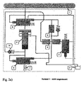
- FIG. 2a shows the initial state in which the first control valve 12 is not electromagnetically driven.
- the nozzle needle 6 keeps the injection nozzle 7 closed and there second control valve 8 is located in the in FIG. 1 illustrated closed position in which the working volume 17 of the pressure booster piston 9 is shut off from the voltage applied to the fuel passage 15 fuel pressure and connected instead with the leakage line 3.
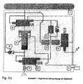
- the first control valve 2 is now electromagnetically driven and causes a pressure drop in the control chamber 12 above the nozzle needle 6, which leads to the opening of the injection nozzle 7.
- the fuel present in the nozzle front chamber 14 at the tip of the nozzle needle 6 is injected into the combustion chamber of the internal combustion engine under the pressure supplied by the fuel accumulator 1.
- the second control valve 8 is not yet actuated, that is, the pressure drop caused by the opening of the first control valve 2 in the control chamber 12 does not yet arrive at the control piston surface 8b of the valve body 8a of the second control valve 8 Effect.
- the first control valve 2 is closed by the end of the energization, whereby a re-increase in the pressure of the control chamber 12 by the flow of fuel from the fuel passage 15 via the inlet throttle 4 is accompanied.
- This increase in the fuel pressure in the control chamber 12 is planted via the throttle 5 located in the control line 12a after a short time Time to the control piston surface 8b on the valve body 8a of the second control valve 8, so that this closed and the working volume 17 of the pressure booster piston 9 is separated from the fuel passage 15.
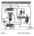
- the second control valve 8 opens the flow of the working volume 17 to the leakage line 3, whereby the pressure booster piston 9 is returned to its initial position.
- the pressure drop occurring in the nozzle antechamber 14 causes a closing of the nozzle needle 6 and thus an end of the injection process.
- FIGS. 3a ) to f) show the time course of various pressures on the fuel injector and piston movement and injection rate during the FIGS. 2a ) to d) during the injection process.
- FIG. 3a is the time constant pressure in the fuel tank 1, shown as the pressure of the common rail.
- FIG. 3b shows the pressure in the control chamber 12 at the back of the nozzle needle. 6
- Figure 3c shows the pressure on the control piston surface 8b of the valve body 8a of the second control valve 8.
- FIG. 3e shows the pressure in the nozzle front chamber 14 in front of the injection nozzle. 7
- FIG. 3f finally shows the course of the injection rate of the fuel injected from the injection nozzle 7 into the combustion chamber of the internal combustion engine.
- a post-injection is effected at low pressure, similar to the pre-injection described above.
Landscapes
- Engineering & Computer Science (AREA)
- Chemical & Material Sciences (AREA)
- Combustion & Propulsion (AREA)
- Mechanical Engineering (AREA)
- General Engineering & Computer Science (AREA)
- Physics & Mathematics (AREA)
- Fluid Mechanics (AREA)
- Fuel-Injection Apparatus (AREA)
Description
- Die Erfindung betrifft einen Kraftstoffinjektor zum Einspritzen von in einem Kraftstoffspeicher unter hohem Druck vorgehaltenem Kraftstoff in den Brennraum einer Brennkraftmaschine nach dem oberbegriff des Anspruchs 1.
- Zum Einspritzen von Kraftstoff, der in einem Kraftstoffspeicher unter hohem Druck vorgehalten ist, in den Brennraum einer Brennkraftmaschine (Common-Rail-Einspritzsystem) sind druckübersetzte Kraftstoffinjektoren bekannt, mit denen der Kraftstoff für, beispielsweise, eine Vor- und/oder Nacheinspritzung mit einem ersten, niedrigeren Druck und für eine, beispielsweise, Haupteinspritzung mit einem zweiten, höheren Druck in den Brennraum der Brennkraftmaschine einspritzbar ist.
- Aus der
DE 199 39 423 A1 ist ein druckübersetzter Kraftstoffinjektor bekannt, der einen hydraulischen Druckübersetzungskolben enthält, welcher ein mit der Einspritzdüse in Verbindung stehendes Fördervolumen mit einem ersten, kleineren Querschnitt und ein wahlweise mit dem Kraftstoffdruck beaufschlagbares Arbeitsvolumen mit einem zweiten, größeren Querschnitt aufweist. Das Arbeitsvolumen ist durch ein elektrisch gesteuertes 3/2-Wege-Ventil walweise zur Auslösung des Arbeitshubs mit dem Kraftstoffdruck des in dem Kraftstoffspeicher unter hohem Druck vorgehaltenen Kraftstoffs oder zur Rückkehr des Druckübersetzungskolbens in seine Ausgangsposition zur Druckentlastung mit einer Leckageleitung verbindbar. Das elektrisch betätigbare Steuerventil bedeutet einen zusätzlichen Aufwand und bedarf einer eigenen elektrischen Ansteuerung. - Ein weiterer druckübersetzter Kraftstoffinjektor ist aus der
DE 100 60 089 A1 bekannt. Hier erfolgt die Ansteuerung eines Druckübersetzungskolbens, welcher ähnlich wie bei dem vorher beschriebenen bekannten druckübersetzten Kraftstoffinjektor aufgebaut ist, durch Druckentlastung eines Differenzraums, welcher der Differenz der Querschnitte von Arbeitsvolumen und Fördervolumen entspricht, über ein elektrisch gesteuertes 2/2-Wege-Ventil. - Aus der
DE 102 29 413 A1 geht ein druckübersetzter Kraftstoffinjektor als bekannt hervor, bei dem zur Ansteuerung der Differenzraum des Druckübersetzungskolbens mit Niederdruck oder dem Kraftstoffdruck beaufschlagt werden kann. Der mit der Düsennadel gekoppelte Steuerkolben hat eine doppelte Funktion. Abhängig von der Position des Steuerkolbens, der ein Schiebeventil bildet, wird eine zum Differenzraum führende Leitung mit Niederdruck verbunden oder die Niederdruckverbindung gesperrt. In der Sperrstellung wird der Differenzraum über eine weitere, gedrosselte Leitungsverbindung mit dem Kraftstoffdruck beaufschlagt. - Aus der
US 2002/088 435 geht eine Kraftstoffeinspritzeinrichtung als bekannt hervor, die einen Steuerraum zur Ansteuerung einer Düsennadel und einen an einen Druckverstärker anschließenden Düsenraum aufweist. Ein Steuerventil dient zur Steuerung des Druckübersetzers durch den in einer mit dem Steuerraum verbundenen Leitung herrschenden Druck. In der zum Steuerventil führenden Leitung ist eine Drossel angeordnet, die zu einem zeitverzögerten Ansprechen des Steuerventils führt. - Die Aufgabe der Erfindung ist es einen verbesserten Kraftstoffinjektor der vorausgesetzten Art zu schaffen. Insbesondere soll ein druckübersetzter Kraftstoffinjektor geschaffen werden, welcher mit geringem Aufwand ansteuerbar ist und einen zuverlässigen Betrieb gewährleistet.
- Die Aufgabe wird durch einen Kraftstoffinjektor mit den Merkmalen des Anspruchs 1 gelöst.
- Vorteilhafte Weiterbildungen und Ausführungsformen des erfindungsgemäßen Kraftstoffinjektors sind in den Unteransprüchen angegeben.
- Durch die Erfindung wird ein Kraftstoffinjektor zum Einspritzen von in einem Kraftstoffspeicher unter hohem Druck vorgehaltenem Kraftstoff in den Brennraum einer Brennkraftmaschine unter mindestens zwei unterschiedlich hohen Einspritzdrücken geschaffen, enthaltend ein Injektorgehäuse, eine in dem Gehäuse längsverschieblich angeordnete Düsennadel und eine von der Düsennadel wahlweise zu öffnenden Einspritzdüse, durch die der Kraftstoff in den Brennraum der Brennkraftmaschine einspritzbar ist, einen mit der Düsennadel zusammenwirkenden, vom Kraftstoffdruck beaufschlagten Steuerraum, der im Sinne eines Öffnens der Einspritzdüse mittels eines ersten Steuerventils druckentlastbar ist und einen Druckübersetzer zum Fördern von einzuspritzendem Kraftstoff unter erhöhtem Druck, wobei der Druckübersetzer durch ein zweites Steuerventil ansteuerbar ist, das zur Betätigung durch den Druck des Kraftstoffs im Steuerraum hydraulisch mit dem Steuerraum verbunden ist. Erfindungsgemäß ist das zweite Steuerventil (8) als 3/2-Wegeventil ausgebildet, welches einen an einer Steuerkolbenfläche (8b) von dem im Steuerraum (12) herrschenden Kraftstoffdruck beaufschlagten Ventilkörper (8a) aufweist.
- Es ist vorgesehen, dass die Steuerkolbenfläche über eine Leitungsverbindung mit dem Steuerraum gekoppelt ist, welche eine das zeitliche Ansprechverhalten des zweiten Steuerventils bestimmende Drossel enthält.
- Weiterhin ist es vorgesehen, dass der Drossel ein in Strömungsrichtung vom Steuerraum zu der Steuerkolbenfläche des zweiten Steuerventils durchgängiges Rückschlagventil parallelgeschaltet ist.
- Der erfindungsgemäße Kraftstoffinjektor ist in vorteilhafter Weise zum Einspritzen von Kraftstoff, insbesondere auch von Schweröl in den Brennraum einer Brennkraftmaschine mit unterschiedlichen Druckniveaus geeignet, insbesondere für eine Vor- und/oder Nacheinspritzung von Kraftstoff mit dem Druck des in dem Kraftstoffspeicher (Common-Rail) unter hohem Druck vorgehaltenen Kraftstoffs, sowie für eine Haupteinspritzung mit einem durch den Druckübersetzer bewirkten Höchstdruck.
- Zur Darstellung von Einspritzvorgängen auf verschiedenen Druckniveaus wird der Ventilkörper des Steuerventils zeitlich verzögert mit dem im Steuerraum, herrschenden Kraftstoffdruck beaufschlagt. Insbesondere ist damit eine Vor- und Nacheinspritzung und der Beginn der Haupteinspritzung auf niedrigerem Druckniveau als die Haupteinspritzung möglich, da die Druckübersetzung zeitlich verzögert anspricht.
- Gemäß einer besonders vorteilhaften Ausführungsform der Erfindung ist es vorgesehen, dass der Druckübersetzer einen Druckübersetzungskolben enthält, der an seiner Vorderseite ein mit der Einspritzdüse in Verbindung stehendes, einen ersten, kleineren Querschnitt aufweisendes Fördervolumen und an seiner Rückseite ein einen zweiten, größeren Querschnitt aufweisendes Arbeitsvolumen aufweist, wobei das Arbeitsvolumen über das zweite Steuerventil im Sinne eines Förderns von Kraftstoff durch den Druckübersetzungskolben unter erhöhtem Druck wahlweise mit dem Kraftstoffdruck beaufschlagbar ist.
- Gemäß einer anderen vorteilhaften Ausführungsform der Erfindung ist es vorgesehen, dass der Druckübersetzer einen Druckübersetzungskolben enthält, der an seiner Vorderseite ein mit der Einspritzdüse in Verbindung stehendes, einen ersten, kleineren Querschnitt aufweisendes Fördervolumen und an seiner Rückseite ein einen zweiten, größeren Querschnitt aufweisendes Arbeitsvolumen aufweist, wobei ein an der Vorderseite des Druckübersetzungskolbens weiterhin vorhandenes, einen dritten Querschnitt aufweisendes Differenzvolumen, das einer Differenz der Querschnitte von Arbeitsvolumen und Fördervolumen entspricht, über das zweite Steuerventil im Sinne eines Förderns von Kraftstoff durch den Druckübersetzungskolben unter erhöhtem Druck wahlweise druckentlastbar ist.
- Zweckmäßigerweise verbindet das Steuerventil (8) eine vom Steuerventil (18) zum Druckübersetzungskolben (9) führende Leitung entweder mit einer Leckageleitung (3) oder einer mit dem Kraftstoffspeicher (1) in Verbindung stehenden Kraftstoffleitung (15).
- Gemäß einer vorteilhaften Ausführungsform der Erfindung ist es vorgesehen, dass zeitliche Ansprechverhalten des zweiten Steuerventils so bemessen ist, dass bei einer kurzen Druckentlastung des Steuerraums für eine Vor- und/oder Nacheinspritzung von Kraftstoff mit nicht erhöhtem Druck eine Freigabe der Einspritzdüse ohne wirksame Ansteuerung des Druckübersetzers und bei einer längeren Druckentlastung des Steu erraums für eine Haupteinspritzung von Kraftstoff mit erhöhtem Druck eine Freigabe der Düsennadel mit wirksamer Ansteuerung des Druckübersetzers erfolgt.
- Im folgenden wird ein Ausführungsbeispiel des erfindungsgemäßen Kraftstoffinjektors anhand der Zeichnung erläutert.
- Es zeigen:
-
Figur 1 eine schematisierte Darstellung eines druckübersetzten Kraftstoffinjektors gemäß einem Ausführungsbeispiel der Erfindung; -
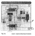
Figur 2a ) bis d) jeweilige Hydraulikpläne des druckübersetzten Kraftstoffinjektors gemäß dem Ausführungsbeispiel der Erfindung, welche vier verschiedene zustände beim Betrieb desselben zeigen; und -
Figur 3a ) bis f) Zeitdiagramme der Verläufe von verschiedenen Drücken, Kolbenbewegung und Einspritzrate bei dem druckübersetzten Kraftstoffinjektor gemäß dem beschriebenen Ausführungsbeispiel. - In
Figur 1 ist ein Kraftstoffinjektor dargestellt, der zum Einspritzen von in einem Kraftstoffspeicher 1 (Common-Rail) unter hohem Druck vorgehaltenem Kraftstoff vorgesehen ist. Der Kraftstoffinjektor umfasst ein, nur teilweise .dargestelltes, Injektorgehäuse 11, in welchem eine Düsennadel 6 längsverschieblich angeordnet ist, die eine an deren vorderen Ende vorgesehene Einspritzdüse 7 zum Einspritzen des Kraftstoffs wahlweise freigibt. An der Rückseite der Düsennadel 6, welche durch eine Feder 13 in Schließrichtung vorbelastet ist, ist ein Steuerraum 12 vorgesehen, welcher über eine Zulaufdrossel 4 von dem in dem Kraftstoffspeicher 1 unter hohem Druck vorgehaltenem Kraftstoff beaufschlagt und über ein erstes Steuerventil 2 wahlweise druckentlastbar ist. Der in dem Kraftstoffspeicher 1 unter hohem Druck vorgehaltene Kraftstoff ist einem die Spitze der Düsennadel 6 ringförmig umgebenden Düsenvorraum 14 über einen Kraftstoffkanal 15 zuführbar. - Weiterbar enthält der Kraftstoffinjektor einen Druckübersetzer 19, welcher einen Druckübersetzungskolben 9 umfasst, an dessen Vorderseite ein einen ersten, kleineren Querschnitt aufweisendes Fördervolumen 16 und an dessen Rückseite ein einen zweiten, größeren Querschnitt aufweisendes Arbeitsvolumen 17 vorgesehen ist. Das Fördervolumen 16 des Druckübersetzungskolbens 9 ist im Zuge des Kraftstofficanals 15 ebenfalls mit dem Düsenvorraum 14 verbunden, wobei sich stromaufwärts des Fördervolumens 16 in dem Kraftstoffkanal 15 ein Rückschlagventil 10 befindet, welches einen Rückstrom von Kraftstoff aus dem Fördervolumen 16 nach stromaufwärts verhindert. Ein weiterhin vorgesehenes zweites Steuerventil 8 ist in Form eines 3/2-Wege-Ventils vorgesehen, welches das an der Rückseite des Druckübersetzungskolbens 9 vorgesehene Arbeitsvolumen 17 wahlweise mit dem Kraftstoffkanal 15 verbindet oder über eine Leckageleitung 3 druckentlastet.
- Das zweite Steuerventil 8 enthält einen Ventilkörper 8a, an welchem eine Steuerkolbenfläche 8b vorgesehen ist, die über eine Steuerleitung 12a von dem im Steuerraum 12 herrschenden Kraftstoffdruck beaufschlagt wird. Durch den auf die Steuerkolbenfläche 8b wirkenden Kraftstoffdruck des Steuerraums 12 wird der Ventilkörper 8a des zweiten Steuerventils 8 in eine erste, geschlossene Stellung gezwungen, in welcher ein Zustrom von dem unter hohem Druck stehenden Kraftstoff vom Kraftstoffkanal 15 zum Arbeitsvolumen 17 des Druckübersetzungskolbens 9 gesperrt und andererseits die Verbindung des Arbeitsvolumens 17 zu der Leckageleitung 3 freigegeben wird.
- In der von dem Steuerraum 12 zu der Steuerkolbenfläche 8b des Ventilkörpers 8a führenden Steuerleitung 12a ist eine Drossel 5 angeordnet, durch welche das zeitliche Ansprechverhalten des zweiten Steuerventils 8 gegenüber Druckänderungen in dem Steuerraum 12 in Ansprache auf ein Öffnen und Schließen des ersten Steuerventils 2 bestimmt ist. Dieser Drossel 5 ist ein Rückschlagventil 5a parallelgeschaltet, welches in Richtung vom Steuerraum 12 zur Steuerkolbenfläche 8b durchgängig ist. Der Druckübersetzer 19 wird somit in Ansprache auf den im Steuerraum 12 herrschenden Druck durch das zweite Steuerventil 8 gesteuert.
- Anhand der
Figuren 2a ) bis d) sollen nun verschiedene Phasen beim Betrieb des erfindungsgemäßen druckübersetzten Kraftstoffinjektors beschrieben werden. -
Figur 2a ) zeigt den Ausgangszustand, in welchem das erste Steuerventil 12 elektromagnetisch nicht angesteuert ist. Die Düsennadel 6 hält die Einspritzdüse 7 geschlossen und da zweite Steuerventil 8 befindet sich in der inFigur 1 dargestellten geschlossenen Stellung, in welcher das Arbeitsvolumen 17 des Druckübersetzungskolbens 9 von dem in dem Kraftstoffkanal 15 anliegenden Kraftstoffdruck abgesperrt und anstelle dessen mit der Leckageleitung 3 verbunden ist. - In dem in
Figur 2b ) gezeigten Zustand ist das erste Steuerventil 2 nun elektromagnetisch angesteuert und bewirkt einen Druckabfall in dem Steuerraum 12 oberhalb der Düsennadel 6, was zum Öffnen der Einspritzdüse 7 führt. Der im Düsenvorraum 14 an der Spitze der Düsennadel 6 anliegende Kraftstoff wird unter dem von dem Kraftstoffspeicher 1 gelieferten Druck in den Brennraum der Brennkraftmaschine eingespritzt. Auf Grund der durch die Drossel 5 bewirkten zeitlichen Verzögerung wird das zweite Steuerventil 8 noch nicht betätigt, das heißt, der im Steuerraum 12 durch das Öffnen des ersten Steuerventils 2 bewirkte Druckabfall kommt an der Steuerkolbenfläche 8b des Ventilkörpers 8a des zweiten Steuerventils 8 noch nicht zur Wirkung. Bei einer Beendigung der Ansteuerung durch das erste Steuerventils 2 vor Wirksamwerden des Druckabfalls im Steuerraum 12 am zweiten Steuerventil 8 findet eine Einspritzung nur unter dem Druck des Kraftstoffspeichers 1 ohne Betätigung des Druckübersetzers 19 statt. Auf diese Art sind eine Vor- und/oder Nacheinspritzung mit einem ersten, niedrigeren Druckniveau realisierbar. - Wenn jedoch das erste Steuerventil 2 über einen dem gegenüber längeren Zeitraum bestromt wird, wird der in
Figur 2c ) gezeigte dritte Betriebszustand wirksam. Über die Drossel 5 wird der im Steuerraum 12 stattfindende Druckabfall nun auch an der Steuerkolbenfläche 8b des Ventilkörpers 8a des zweiten Steuerventils 8 wirksam, so dass durch eine Öffnungsbewegung des Ventilkörpers 8a eine Verbindung vom Kraftstoffkanal 15 zum Arbeitsvolumen 17 an der Rückseite des Druckübersetzungskolbens 9 stattfindet, welche eine Bewegung des Druckübersetzungskolbens 9 im Sinne einer Förderung von Kraftstoff aus dem an seiner Vorderseite befindlichen Fördervolumen 16 zum Düsenvorraum 14 an der Einspritzdüse 7 führt. Hierdurch wird der Kraftstoffdruck während der Einspritzung dementsprechend erhöht, wobei ein Rückstrom von Kraftstoff aus dem Fördervolumen 16 zum Kraftstoffkanal 15 durch das Rückschlagventil 10 verhindert wird. Bei der Bewegung des Druckübersetzungskolbens 9 strömt in einem Differenzvolumen 18, welches der Differenz der Querschnitte von Arbeitsvolumen 17 und Fördervolumen 16 entspricht, befindlicher Kraftstoff in die Leckageleitung 3. - 1 Am Ende des Einspritzvorgangs, vergleiche
Figur 2d ), wird durch Ende der Bestromung das erste Steuerventil 2 geschlossen, womit ein Wiederanstieg des Drucks des Steuerraums 12 durch Nachfließen von Kraftstoff aus dem Kraftstoffkanal 15 über die Zulaufdrossel 4 einhergeht. Diese Erhöhung des Kraftstoffdrucks im Steuerraum 12 pflanzt sich über die in der Steuerleitung 12a befindliche Drossel 5 nach einer kurzen Zeit zur Steuerkolbenfläche 8b am Ventilkörper 8a des zweiten Steuerventils 8 fort, so das dieses geschlossen und das Arbeitsvolumen 17 des Druckübersetzungskolbens 9 vom Kraftstoffkanal 15 getrennt wird. Gleichzeitig öffnet das zweite Steuerventil 8 den Ablauf des Arbeitsvolumen 17 zur Leckageleitung 3, wodurch der Druckübersetzungskolben 9 in seine Ausgangsstellung zurückgeführt wird. Der im Düsenvorraum 14 stattfindende Druckabfall bewirkt ein Schließen der Düsennadel 6 und damit ein Ende des Einspritzvorgangs. - Die
Figuren 3a ) bis f) zeigen den zeitlichen Verlauf verschiedener Drücke am Kraftstoffinjektor und von Kolbenbewegung und Einspritzrate während der anhand derFiguren 2a ) bis d) beschriebenen Phasen beim Einspritzvorgang. - In
Figur 3a ) ist der zeitlich konstante Druck im Kraftstoffspeicher 1, als der Druck des Common-Rail dargestellt.Figur 3b ) zeigt den Druck im Steuerraum 12 an der Rückseite der Düsennadel 6. -
Figur 3c ) zeigt den Druck an der Steuerkolbenfläche 8b des Ventilkörpers 8a des zweiten Steuerventils 8. -
Figur 3d ) zeigt die Bewegung des Druckübersetzungskolbens 9. -
Figur 3e ) zeigt den Druck im Düsenvorraum 14 vor der Einspritzdüse 7. -
Figur 3f ) schließlich zeigt den Verlauf der Einspritzrate des von der Einspritzdüse 7 in den Brennraum der Brennkraftmaschine eingespritzten Kraftstoffs. - Wie ersichtlich ist, bewirkt eine kurze Ansteuerung des ersten Steuerventils 2 am Anfang des Einspritzvorgangs nur ein kurzes Absenken des Drucks im Steuerraum 12, vergleiche
Figur 3b ), verbunden mit einer kurzen Voreinspritzung von Kraftstoff in den Brennraum der Brennkraftmaschine, vergleiche Figur 3f). - Bei einer dann folgenden längeren Ansteuerung des ersten Steuerventils 2 sinkt der Druck im Steuerraum 12 für eine längere Zeit ab, vergleiche
Figur 3b ), wobei sich dieser Druckabfall über die Drossel 5 auf das zweite Steuerventil 8 überträgt, vergleicheFigur 3c ), wodurch eine Bewegung des Druckübersetzungskolbens 9, vergleicheFigur 3d ), im Sinne einer Förderung von Kraftstoff unter erhöhtem Druck, vergleicheFigur 3e ) bewirkt wird. Damit ergibt sich die inFigur 3f ) dargestellte Haupteinspritzung mit erhöhter Einspritzrate. - Nach Entstromung des ersten Steuerventils 2 kehren die Düsennadel 6 in ihren geschlossenen Zustand und der Druckübersetzungskolben 9 in seine Ausgangsposition zurück.
- Bei einer dann noch folgenden weiteren kurzen Bestromung des ersten Steuerventils 2 wird eine Nacheinspritzung mit niedrigem Druck bewirkt, ähnlich der vorher beschriebenen Voreinspritzung.
- Abweichend von den anhand der
Figur 3 beschriebenen beispielhaften zeitlichen Verläufen kann der Einspritzvorgang selbstverständlich auch in anderer Weise gesteuert werden. -
- 1
- Kraftstoffspeicher
- 2
- erstes Steuerventil (Common-Rail)
- 3
- Leckageleitung
- 4
- Zulaufdrossel
- 5
- Drossel
- 5a
- Rückschlagventil
- 6
- Düsennadel
- 7
- Einspritzdüse
- 8
- zweites Steuerventil
- 8a
- Ventilkörper
- 8b
- Steuerkolbenfläche
- 9
- Druckübersetzungskolben
- 10
- Rückschlagventil
- 11
- Injektorgehäuse
- 12
- Steuerraum
- 12a
- Steuerleitung
- 13
- Feder
- 14
- Düsenvorraum
- 15
- Kraftstoffkanal
- 16
- Fördervolumen
- 17
- Arbeitsvolumen
- 18
- Differenzvolumen
- 19
- Druckübersetzer
Claims (6)
- Kraftstoffinjektor zum Einspritzen von in einem Kraftstoffspeicher (1) unter hohem Druck vorgehaltenem Kraftstoff in den Brennraum einer Brennkraftmaschine unter mindestens zwei unterschiedlich hohen Einspritzdrücken, enthaltend ein Injektorgehäuse (11), eine in dem Gehäuse (11) längsverschieblich angeordnete Düsennadel (6) und eine von der Düsennadel (6) wahlweise zu öffnenden Einspritzdüse (7), durch die der Kraftstoff in den Brennraum der Brennkraftmaschine einspritzbar ist, einen mit der Düsennadel (6) zusammenwirkenden, vom Kraftstoffdruck beaufschlagten Steuerraum (12), der im Sinne eines Öffnens der Einspritzdüse (7) mittels eines ersten Steuerventils (2) druckentlastbar ist, und enthaltend einen Druckübersetzer (19) zum Fördern von einzuspritzendem Kraftstoff unter erhöhtem Druck, wobei der Druckübersetzer (19) durch ein zweites Steuerventil (8) ansteuerbar ist, das zur Betätigung durch den Druck des Kraftstoffs im Steuerraum (12) hydraulisch mit dem Steuerraum (12) gekoppelt ist, wobei das zweite Steuerventil (8) einen an einer Steuerkolbenfläche (8b) von dem im Steuerraum (12) herrschenden Kraftstoffdruck beaufschlagbaren Ventilkörper (8a) aufweist, wobei die Steuerkolbenfläche (8b) über eine Leitungsverbindung mit dem Steuerraum (12) gekoppelt ist, welche eine das zeitliche Ansprechverhalten des zweiten Steuerventils (8) bestimmende Drossel (5) enthält,
dadurch gekennzeichnet,
dass das zweite Steuerventil (8) als 3/2-Wegeventil ausgebildet ist und dass der Drossel (5) ein in Strömungsrichtung vom Steuerraum (12) zu der Steuerkolbenfläche (8b) des zweiten Steuerventils (8) durchgängiges Rückschlagventil (5a) parallelgeschaltet ist. - Kraftstoffinjektor nach Anspruch 1,
dadurch gekennzeichnet,
dass der Ventilkörper (8a) zeitlich verzögert mit dem im Steuerraum (12) herrschenden Kraftstoffdruck beaufschlagbar ist. - Kraftstoffinjektor nach Anspruch 1 oder 2,
dadurch gekennzeichnet,
dass der Druckübersetzer (19) einen Druckübersetzungskolben (9) enthält, der an seiner Vorderseite ein mit der Einspritzdüse (7) in Verbindung stehendes, einen ersten, kleineren Querschnitt aufweisendes Fördervolumen (16) und an seiner Rückseite ein einen zweiten, größeren Querschnitt aufweisendes Arbeitsvolumen (17) aufweist, wobei das Arbeitsvolumen (17) über das zweite Steuerventil (8) im Sinne eines Förderns von Kraftstoff durch den Druckübersetzungskolben (9) unter erhöhtem Druck mit dem Kraftstoffdruck beaufschlagbar ist. - Kraftstoffinjektor nach Anspruch 1 oder 2,
dadurch gekennzeichnet,
dass der Druckübersetzer (19) einen Druckübersetzungskolben (9) enthält, der an seiner Vorderseite ein mit der Einspritzdüse (7) in Verbindung stehendes, einen ersten, kleineren Querschnitt aufweisendes Fördervolumen (16) und an seiner Rückseite ein einen zweiten, größeren Querschnitt aufweisendes Arbeitsvolumen (17) aufweist, wobei ein an der Vorderseite des Druckübersetzungskolbens (9) weiterhin vorhandenes, einen dritten Querschnitt aufweisendes Differenzvolumen (18), das einer Differenz der Querschnitte von Arbeitsvolumen (17) und Fördervolumen (16) entspricht, über das zweite Steuerventil (8) im Sinne eines Förderns von Kraftstoff durch den Druckübersetzungskolben (9) unter erhöhtem Druck druckentlastbar ist. - Kraftstoffinjektor nach einem der Ansprüche 1 bis 4,
dadurch gekennzeichnet,
dass das Steuerventil (8) eine vom Steuerventil (18) zum Druckübersetzungskolben (9) führende Leitung entweder mit einer Leckageleitung (3) oder einer mit dem Kraftstoffspeicher (1) in Verbindung stehenden Kraftstoffleitung (15) verbindet. - Kraftstoffinjektor nach einem der Ansprüche 1 bis 5,
dadurch gekennzeichnet,
dass zeitliche Ansprechverhalten des zweiten Steuerventils (8) so bemessen ist, dass bei einer kurzen Druckentlastung des Steuerraums (12) für eine Vor- und/oder Nacheinspritzung von Kraftstoff mit nicht erhöhtem Druck eine Freigabe der Einspritzdüse (7) ohne wirksame Ansteuerung des Druckübersetzers (19) und bei einer längeren Druckentlastung des Steuerraums (12) für eine Haupteinspritzung von Kraftstoff mit erhöhtem Druck eine Freigabe der Düsennadel (7) mit wirksamer Ansteuerung des Druckübersetzers (19) erfolgt.
Applications Claiming Priority (2)
| Application Number | Priority Date | Filing Date | Title |
|---|---|---|---|
| DE102005033123A DE102005033123B3 (de) | 2005-07-15 | 2005-07-15 | Kraftstoffinjektor |
| PCT/EP2006/006796 WO2007009641A1 (de) | 2005-07-15 | 2006-07-12 | Kraftstoffinjektor |
Publications (2)
| Publication Number | Publication Date |
|---|---|
| EP1907686A1 EP1907686A1 (de) | 2008-04-09 |
| EP1907686B1 true EP1907686B1 (de) | 2009-05-20 |
Family
ID=36993341
Family Applications (1)
| Application Number | Title | Priority Date | Filing Date |
|---|---|---|---|
| EP06762543A Expired - Lifetime EP1907686B1 (de) | 2005-07-15 | 2006-07-12 | Kraftstoffinjektor |
Country Status (6)
| Country | Link |
|---|---|
| EP (1) | EP1907686B1 (de) |
| JP (1) | JP4869342B2 (de) |
| KR (1) | KR101001002B1 (de) |
| AT (1) | ATE431901T1 (de) |
| DE (2) | DE102005033123B3 (de) |
| WO (1) | WO2007009641A1 (de) |
Families Citing this family (2)
| Publication number | Priority date | Publication date | Assignee | Title |
|---|---|---|---|---|
| DK178655B1 (en) * | 2015-03-20 | 2016-10-17 | Man Diesel & Turbo Filial Af Man Diesel & Turbo Se Tyskland | Fuel valve for injecting fuel into a combustion chamber of a large self-igniting turbocharged two-stroke internal combustion engine |
| CN111433450B (zh) * | 2017-12-08 | 2022-01-28 | 沃尔沃卡车集团 | 用于共轨燃料喷射系统的装置 |
Family Cites Families (5)
| Publication number | Priority date | Publication date | Assignee | Title |
|---|---|---|---|---|
| JP2885076B2 (ja) * | 1994-07-08 | 1999-04-19 | 三菱自動車工業株式会社 | 蓄圧式燃料噴射装置 |
| DE19939423A1 (de) * | 1999-08-20 | 2001-03-01 | Bosch Gmbh Robert | Kraftstoffeinspritzsystem für eine Brennkraftmaschine |
| DE10060089A1 (de) * | 2000-12-02 | 2002-06-20 | Bosch Gmbh Robert | Kraftstoffeinspritzeinrichtung |
| DE10063545C1 (de) * | 2000-12-20 | 2002-08-01 | Bosch Gmbh Robert | Kraftstoffeinspritzeinrichtung |
| DE10229413A1 (de) * | 2002-06-29 | 2004-01-29 | Robert Bosch Gmbh | Druckübersetzersteuerung durch Bewegung eines Einspritzventilgliedes |
-
2005
- 2005-07-15 DE DE102005033123A patent/DE102005033123B3/de not_active Expired - Fee Related
-
2006
- 2006-07-12 WO PCT/EP2006/006796 patent/WO2007009641A1/de not_active Ceased
- 2006-07-12 JP JP2008520786A patent/JP4869342B2/ja not_active Expired - Fee Related
- 2006-07-12 KR KR1020077030330A patent/KR101001002B1/ko not_active Expired - Fee Related
- 2006-07-12 EP EP06762543A patent/EP1907686B1/de not_active Expired - Lifetime
- 2006-07-12 AT AT06762543T patent/ATE431901T1/de active
- 2006-07-12 DE DE502006003778T patent/DE502006003778D1/de not_active Expired - Lifetime
Also Published As
| Publication number | Publication date |
|---|---|
| ATE431901T1 (de) | 2009-06-15 |
| WO2007009641A1 (de) | 2007-01-25 |
| KR101001002B1 (ko) | 2010-12-14 |
| EP1907686A1 (de) | 2008-04-09 |
| JP2009501289A (ja) | 2009-01-15 |
| DE102005033123B3 (de) | 2006-12-21 |
| DE502006003778D1 (de) | 2009-07-02 |
| KR20080028377A (ko) | 2008-03-31 |
| JP4869342B2 (ja) | 2012-02-08 |
Similar Documents
| Publication | Publication Date | Title |
|---|---|---|
| EP1520096A1 (de) | Speichereinspritzsystem mit variodüse und druckübersetzungseinrichtung | |
| DE2742466A1 (de) | Pumpe-duese fuer luftverdichtende einspritzbrennkraftmaschinen | |
| EP1520099B1 (de) | Druckübersetzer kraftstoffinjektor mit schnellem druckabbau bei einspritzende | |
| EP1252437B1 (de) | Einspritzeinrichtung und verfahren zum einspritzen von fluid | |
| EP1593839B1 (de) | Kraftstoffinjektor für Verbrennungskraftmaschinen mit mehrstufigem Steuerventil | |
| DE10024268A1 (de) | Vorrichtung zur Benzindirekteinspritzung in einer Kolbenbrennkraftmaschine | |
| EP1552137B1 (de) | Einrichtung zur unterdrückung von druckwellen an speichereinspritzsystemen | |
| EP1651862B1 (de) | Schaltventil für einen kraftstoffinjektor mit druckübersetzer | |
| DE10229415A1 (de) | Einrichtung zur Nadelhubdämpfung an druckgesteuerten Kraftstoffinjektoren | |
| DE102004022267A1 (de) | Verfahren und Vorrichtung zur Formung des Einspritzdruckes an einem Kraftstoffinjektor | |
| EP1520095B1 (de) | Druckübersetzersteuerung durch bewegung eines einspritzventilgliedes | |
| EP1185785B1 (de) | Einspritzsystem | |
| EP1925812B1 (de) | Kraftstoffeinspritzventil für Brennkraftmaschinen | |
| EP1558843A1 (de) | Kraftstoff-einspritzeinrichtung für brennkraftmaschinen | |
| EP1144859B1 (de) | Einspritzeinrichtung und verfahren zum einspritzen von fluid | |
| EP1260705B1 (de) | Kraftstoffeinspritzeinrichtung für eine Brennkraftmaschine | |
| EP1931874A1 (de) | Vorrichtung zum einspritzen von kraftstoff in den brennraum einer brennkraftmaschine | |
| DE10109610A1 (de) | Kraftstoffeinspritzeinrichtung für Brennkraftmaschinen | |
| DE19734354A1 (de) | Kraftstoffeinspritzsystem für eine Brennkraftmaschine | |
| DE102005033123B3 (de) | Kraftstoffinjektor | |
| EP1483499A1 (de) | Einrichtung zur druckmodulierten formung des einspritzverlaufes | |
| DE102005032464A1 (de) | Kraftstoffinjektor mit Vorsteuerraum | |
| EP1377745B1 (de) | Verfahren zum betreiben einer pumpe-düse-einheit sowie pumpe-düse-einheit | |
| DE10315489B3 (de) | Kraftstoffinjektor mit Druckübersetzer und in ein Düsenmodul integriertem Dämpfungskolben | |
| DE2641203C2 (de) | Kraftstoffeinspritzpumpe für eine Brennkraftmaschine |
Legal Events
| Date | Code | Title | Description |
|---|---|---|---|
| PUAI | Public reference made under article 153(3) epc to a published international application that has entered the european phase |
Free format text: ORIGINAL CODE: 0009012 |
|
| 17P | Request for examination filed |
Effective date: 20080112 |
|
| AK | Designated contracting states |
Kind code of ref document: A1 Designated state(s): AT BE BG CH CY CZ DE DK EE ES FI FR GB GR HU IE IS IT LI LT LU LV MC NL PL PT RO SE SI SK TR |
|
| 17Q | First examination report despatched |
Effective date: 20080523 |
|
| GRAP | Despatch of communication of intention to grant a patent |
Free format text: ORIGINAL CODE: EPIDOSNIGR1 |
|
| DAX | Request for extension of the european patent (deleted) | ||
| GRAS | Grant fee paid |
Free format text: ORIGINAL CODE: EPIDOSNIGR3 |
|
| GRAA | (expected) grant |
Free format text: ORIGINAL CODE: 0009210 |
|
| AK | Designated contracting states |
Kind code of ref document: B1 Designated state(s): AT BE BG CH CY CZ DE DK EE ES FI FR GB GR HU IE IS IT LI LT LU LV MC NL PL PT RO SE SI SK TR |
|
| REG | Reference to a national code |
Ref country code: GB Ref legal event code: FG4D Free format text: NOT ENGLISH |
|
| REG | Reference to a national code |
Ref country code: CH Ref legal event code: EP |
|
| REG | Reference to a national code |
Ref country code: IE Ref legal event code: FG4D Free format text: LANGUAGE OF EP DOCUMENT: GERMAN |
|
| REF | Corresponds to: |
Ref document number: 502006003778 Country of ref document: DE Date of ref document: 20090702 Kind code of ref document: P |
|
| PG25 | Lapsed in a contracting state [announced via postgrant information from national office to epo] |
Ref country code: ES Free format text: LAPSE BECAUSE OF FAILURE TO SUBMIT A TRANSLATION OF THE DESCRIPTION OR TO PAY THE FEE WITHIN THE PRESCRIBED TIME-LIMIT Effective date: 20090831 Ref country code: LT Free format text: LAPSE BECAUSE OF FAILURE TO SUBMIT A TRANSLATION OF THE DESCRIPTION OR TO PAY THE FEE WITHIN THE PRESCRIBED TIME-LIMIT Effective date: 20090520 Ref country code: PT Free format text: LAPSE BECAUSE OF FAILURE TO SUBMIT A TRANSLATION OF THE DESCRIPTION OR TO PAY THE FEE WITHIN THE PRESCRIBED TIME-LIMIT Effective date: 20090920 |
|
| NLV1 | Nl: lapsed or annulled due to failure to fulfill the requirements of art. 29p and 29m of the patents act | ||
| PG25 | Lapsed in a contracting state [announced via postgrant information from national office to epo] |
Ref country code: IS Free format text: LAPSE BECAUSE OF FAILURE TO SUBMIT A TRANSLATION OF THE DESCRIPTION OR TO PAY THE FEE WITHIN THE PRESCRIBED TIME-LIMIT Effective date: 20090920 Ref country code: LV Free format text: LAPSE BECAUSE OF FAILURE TO SUBMIT A TRANSLATION OF THE DESCRIPTION OR TO PAY THE FEE WITHIN THE PRESCRIBED TIME-LIMIT Effective date: 20090520 Ref country code: NL Free format text: LAPSE BECAUSE OF FAILURE TO SUBMIT A TRANSLATION OF THE DESCRIPTION OR TO PAY THE FEE WITHIN THE PRESCRIBED TIME-LIMIT Effective date: 20090520 Ref country code: PL Free format text: LAPSE BECAUSE OF FAILURE TO SUBMIT A TRANSLATION OF THE DESCRIPTION OR TO PAY THE FEE WITHIN THE PRESCRIBED TIME-LIMIT Effective date: 20090520 Ref country code: SI Free format text: LAPSE BECAUSE OF FAILURE TO SUBMIT A TRANSLATION OF THE DESCRIPTION OR TO PAY THE FEE WITHIN THE PRESCRIBED TIME-LIMIT Effective date: 20090520 Ref country code: SE Free format text: LAPSE BECAUSE OF FAILURE TO SUBMIT A TRANSLATION OF THE DESCRIPTION OR TO PAY THE FEE WITHIN THE PRESCRIBED TIME-LIMIT Effective date: 20090820 |
|
| REG | Reference to a national code |
Ref country code: IE Ref legal event code: FD4D |
|
| PG25 | Lapsed in a contracting state [announced via postgrant information from national office to epo] |
Ref country code: IE Free format text: LAPSE BECAUSE OF FAILURE TO SUBMIT A TRANSLATION OF THE DESCRIPTION OR TO PAY THE FEE WITHIN THE PRESCRIBED TIME-LIMIT Effective date: 20090520 Ref country code: DK Free format text: LAPSE BECAUSE OF FAILURE TO SUBMIT A TRANSLATION OF THE DESCRIPTION OR TO PAY THE FEE WITHIN THE PRESCRIBED TIME-LIMIT Effective date: 20090520 Ref country code: RO Free format text: LAPSE BECAUSE OF FAILURE TO SUBMIT A TRANSLATION OF THE DESCRIPTION OR TO PAY THE FEE WITHIN THE PRESCRIBED TIME-LIMIT Effective date: 20090520 Ref country code: EE Free format text: LAPSE BECAUSE OF FAILURE TO SUBMIT A TRANSLATION OF THE DESCRIPTION OR TO PAY THE FEE WITHIN THE PRESCRIBED TIME-LIMIT Effective date: 20090520 Ref country code: CZ Free format text: LAPSE BECAUSE OF FAILURE TO SUBMIT A TRANSLATION OF THE DESCRIPTION OR TO PAY THE FEE WITHIN THE PRESCRIBED TIME-LIMIT Effective date: 20090520 |
|
| BERE | Be: lapsed |
Owner name: L'ORANGE G.M.B.H. Effective date: 20090731 |
|
| PG25 | Lapsed in a contracting state [announced via postgrant information from national office to epo] |
Ref country code: SK Free format text: LAPSE BECAUSE OF FAILURE TO SUBMIT A TRANSLATION OF THE DESCRIPTION OR TO PAY THE FEE WITHIN THE PRESCRIBED TIME-LIMIT Effective date: 20090520 Ref country code: MC Free format text: LAPSE BECAUSE OF NON-PAYMENT OF DUE FEES Effective date: 20090731 |
|
| PLBE | No opposition filed within time limit |
Free format text: ORIGINAL CODE: 0009261 |
|
| STAA | Information on the status of an ep patent application or granted ep patent |
Free format text: STATUS: NO OPPOSITION FILED WITHIN TIME LIMIT |
|
| PG25 | Lapsed in a contracting state [announced via postgrant information from national office to epo] |
Ref country code: BG Free format text: LAPSE BECAUSE OF FAILURE TO SUBMIT A TRANSLATION OF THE DESCRIPTION OR TO PAY THE FEE WITHIN THE PRESCRIBED TIME-LIMIT Effective date: 20090820 |
|
| REG | Reference to a national code |
Ref country code: FR Ref legal event code: ST Effective date: 20100331 |
|
| 26N | No opposition filed |
Effective date: 20100223 |
|
| PG25 | Lapsed in a contracting state [announced via postgrant information from national office to epo] |
Ref country code: FR Free format text: LAPSE BECAUSE OF NON-PAYMENT OF DUE FEES Effective date: 20090731 |
|
| PG25 | Lapsed in a contracting state [announced via postgrant information from national office to epo] |
Ref country code: BE Free format text: LAPSE BECAUSE OF NON-PAYMENT OF DUE FEES Effective date: 20090731 |
|
| PG25 | Lapsed in a contracting state [announced via postgrant information from national office to epo] |
Ref country code: GR Free format text: LAPSE BECAUSE OF FAILURE TO SUBMIT A TRANSLATION OF THE DESCRIPTION OR TO PAY THE FEE WITHIN THE PRESCRIBED TIME-LIMIT Effective date: 20090821 |
|
| PG25 | Lapsed in a contracting state [announced via postgrant information from national office to epo] |
Ref country code: LU Free format text: LAPSE BECAUSE OF NON-PAYMENT OF DUE FEES Effective date: 20090712 |
|
| PG25 | Lapsed in a contracting state [announced via postgrant information from national office to epo] |
Ref country code: HU Free format text: LAPSE BECAUSE OF FAILURE TO SUBMIT A TRANSLATION OF THE DESCRIPTION OR TO PAY THE FEE WITHIN THE PRESCRIBED TIME-LIMIT Effective date: 20091121 |
|
| PG25 | Lapsed in a contracting state [announced via postgrant information from national office to epo] |
Ref country code: TR Free format text: LAPSE BECAUSE OF FAILURE TO SUBMIT A TRANSLATION OF THE DESCRIPTION OR TO PAY THE FEE WITHIN THE PRESCRIBED TIME-LIMIT Effective date: 20090520 |
|
| PG25 | Lapsed in a contracting state [announced via postgrant information from national office to epo] |
Ref country code: CY Free format text: LAPSE BECAUSE OF FAILURE TO SUBMIT A TRANSLATION OF THE DESCRIPTION OR TO PAY THE FEE WITHIN THE PRESCRIBED TIME-LIMIT Effective date: 20090520 |
|
| PGFP | Annual fee paid to national office [announced via postgrant information from national office to epo] |
Ref country code: FI Payment date: 20140711 Year of fee payment: 9 Ref country code: CH Payment date: 20140721 Year of fee payment: 9 Ref country code: DE Payment date: 20140721 Year of fee payment: 9 |
|
| PGFP | Annual fee paid to national office [announced via postgrant information from national office to epo] |
Ref country code: AT Payment date: 20140611 Year of fee payment: 9 Ref country code: GB Payment date: 20140721 Year of fee payment: 9 |
|
| PGFP | Annual fee paid to national office [announced via postgrant information from national office to epo] |
Ref country code: IT Payment date: 20140723 Year of fee payment: 9 |
|
| REG | Reference to a national code |
Ref country code: DE Ref legal event code: R119 Ref document number: 502006003778 Country of ref document: DE |
|
| REG | Reference to a national code |
Ref country code: CH Ref legal event code: PL |
|
| REG | Reference to a national code |
Ref country code: AT Ref legal event code: MM01 Ref document number: 431901 Country of ref document: AT Kind code of ref document: T Effective date: 20150712 |
|
| GBPC | Gb: european patent ceased through non-payment of renewal fee |
Effective date: 20150712 |
|
| PG25 | Lapsed in a contracting state [announced via postgrant information from national office to epo] |
Ref country code: IT Free format text: LAPSE BECAUSE OF NON-PAYMENT OF DUE FEES Effective date: 20150712 Ref country code: CH Free format text: LAPSE BECAUSE OF NON-PAYMENT OF DUE FEES Effective date: 20150731 Ref country code: GB Free format text: LAPSE BECAUSE OF NON-PAYMENT OF DUE FEES Effective date: 20150712 Ref country code: LI Free format text: LAPSE BECAUSE OF NON-PAYMENT OF DUE FEES Effective date: 20150731 Ref country code: DE Free format text: LAPSE BECAUSE OF NON-PAYMENT OF DUE FEES Effective date: 20160202 |
|
| PG25 | Lapsed in a contracting state [announced via postgrant information from national office to epo] |
Ref country code: FI Free format text: LAPSE BECAUSE OF NON-PAYMENT OF DUE FEES Effective date: 20150712 Ref country code: AT Free format text: LAPSE BECAUSE OF NON-PAYMENT OF DUE FEES Effective date: 20150712 |