EP1907636B1 - Remote control machine with partial or total autonomous control - Google Patents
Remote control machine with partial or total autonomous control Download PDFInfo
- Publication number
- EP1907636B1 EP1907636B1 EP06774113.2A EP06774113A EP1907636B1 EP 1907636 B1 EP1907636 B1 EP 1907636B1 EP 06774113 A EP06774113 A EP 06774113A EP 1907636 B1 EP1907636 B1 EP 1907636B1
- Authority
- EP
- European Patent Office
- Prior art keywords
- tool carrier
- control
- control signal
- signal
- path
- Prior art date
- Legal status (The legal status is an assumption and is not a legal conclusion. Google has not performed a legal analysis and makes no representation as to the accuracy of the status listed.)
- Not-in-force
Links
- 238000000034 method Methods 0.000 claims description 22
- 230000007717 exclusion Effects 0.000 claims description 8
- 230000004044 response Effects 0.000 claims description 6
- 238000012360 testing method Methods 0.000 description 8
- 230000008569 process Effects 0.000 description 5
- 230000006870 function Effects 0.000 description 4
- 239000000969 carrier Substances 0.000 description 2
- 238000010276 construction Methods 0.000 description 2
- 238000005259 measurement Methods 0.000 description 2
- 230000007246 mechanism Effects 0.000 description 2
- 230000009286 beneficial effect Effects 0.000 description 1
- 230000007175 bidirectional communication Effects 0.000 description 1
- 230000008859 change Effects 0.000 description 1
- 230000006854 communication Effects 0.000 description 1
- 238000004891 communication Methods 0.000 description 1
- 238000004590 computer program Methods 0.000 description 1
- 238000013461 design Methods 0.000 description 1
- 238000006073 displacement reaction Methods 0.000 description 1
- 230000000694 effects Effects 0.000 description 1
- 230000002452 interceptive effect Effects 0.000 description 1
- 239000000463 material Substances 0.000 description 1
- 238000012986 modification Methods 0.000 description 1
- 230000004048 modification Effects 0.000 description 1
- 239000011435 rock Substances 0.000 description 1
Images


Classifications
-
- G—PHYSICS
- G05—CONTROLLING; REGULATING
- G05D—SYSTEMS FOR CONTROLLING OR REGULATING NON-ELECTRIC VARIABLES
- G05D1/00—Control of position, course or altitude of land, water, air, or space vehicles, e.g. automatic pilot
- G05D1/0011—Control of position, course or altitude of land, water, air, or space vehicles, e.g. automatic pilot associated with a remote control arrangement
- G05D1/0033—Control of position, course or altitude of land, water, air, or space vehicles, e.g. automatic pilot associated with a remote control arrangement by having the operator tracking the vehicle either by direct line of sight or via one or more cameras located remotely from the vehicle
-
- E—FIXED CONSTRUCTIONS
- E02—HYDRAULIC ENGINEERING; FOUNDATIONS; SOIL SHIFTING
- E02F—DREDGING; SOIL-SHIFTING
- E02F9/00—Component parts of dredgers or soil-shifting machines, not restricted to one of the kinds covered by groups E02F3/00 - E02F7/00
- E02F9/20—Drives; Control devices
- E02F9/2025—Particular purposes of control systems not otherwise provided for
- E02F9/205—Remotely operated machines, e.g. unmanned vehicles
-
- E—FIXED CONSTRUCTIONS
- E02—HYDRAULIC ENGINEERING; FOUNDATIONS; SOIL SHIFTING
- E02F—DREDGING; SOIL-SHIFTING
- E02F9/00—Component parts of dredgers or soil-shifting machines, not restricted to one of the kinds covered by groups E02F3/00 - E02F7/00
- E02F9/24—Safety devices, e.g. for preventing overload
-
- G—PHYSICS
- G05—CONTROLLING; REGULATING
- G05D—SYSTEMS FOR CONTROLLING OR REGULATING NON-ELECTRIC VARIABLES
- G05D1/00—Control of position, course or altitude of land, water, air, or space vehicles, e.g. automatic pilot
- G05D1/02—Control of position or course in two dimensions
- G05D1/021—Control of position or course in two dimensions specially adapted to land vehicles
- G05D1/0276—Control of position or course in two dimensions specially adapted to land vehicles using signals provided by a source external to the vehicle
- G05D1/0278—Control of position or course in two dimensions specially adapted to land vehicles using signals provided by a source external to the vehicle using satellite positioning signals, e.g. GPS
Definitions
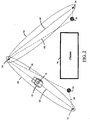
- Figure 1 shows a system for controlling operation of a tool carrier generally indicated by reference numeral 10.
- the system comprises a first remote control 12, a second remote control 14, an antenna assembly 16 supported by the tool carrier 10, and a controller system 18.
- the first remote control 12 has at least one user input device 20 and is adapted to generate a first control signal 22 in response to actuation of the user input device.
- the second remote control 14 may be used by a second operator 24 to generate a second control signal 26 by actuation of a user input device.
- the first control signal 22 may be selected by the controller system 18 when the tool carrier 10 is disposed at the first location 52 or within the first work zone 60. While present in the first work zone 60, the first operator 30 may control the tool carrier 10 with the first work signal 22 to perform a wide variety of activities such as excavating a jobsite or loading materials to be moved to another location. The first operator 30 may then move the tool carrier 10 along the first path 50 to the hand-off point 54. At the hand-off point 54 the first control signal 22 may be deselected by the controller system 18 and the second control signal 26 selected by the controller system to allow control of the tool carrier 10 by the second remote control 14 within the second work zone 62.
- the signal transmitter 70 may be stationed on the worksite to transmit a reference signal to the controller system 18 for establishing a path 74 along which the tool carrier 10 may be steered.
- the reference signal transmitted by the signal transmitter 70 may comprise a radio-frequency signal or a laser beam directed to a laser beam receiver (not shown) supported on the tool carrier 10 and operatively connected to the controller system 18.
- the laser receiver and controller system 18 may be configured to steer the tool carrier 10 along a laser path (not shown) defined by the path of the laser beam received at the tool carrier.
- the controller system 18 could be adapted to move the tool carrier 10 in a variety of directions to maintain contact with the laser beam transmitted from the signal transmitter 70.
- Possessing control of the tool carrier 10, as previously discussed, may comprise several steps and requirements before control is allowed. For example, if the first operator 30 is attempting to control the tool carrier 10 with the first remote control 12, the tool carrier must recognize the first control signal 22 before operation of the tool carrier is allowed.
- the first remote control 12 may serve as a primary controller adapted to take control of the tool carrier 10 from any secondary remote controls.
- the controller system 18 may be configured to allow shared control of the tool carrier for certain operations of the tool carrier. Such a configuration may be useful in instances where a single operator may have difficulty controlling both ground drive 38 and work tool 40 functions.
- the tool carrier may continue along the predetermined path 68.
- Obstacle avoidance sensors 46 and 48 may be activated to detect any obstacles (Step 508) disposed within the predetermined path 68. If an obstacle is detected by sensors 46 or 48, the controller system 18 may halt movement of the tool carrier (Step 506) or alter the predetermined path 68 to avoid the obstacle and proceed to the pre-programmed destination point. In the event that no obstacles are detected or the path altered to avoid any obstacles, the tool carrier will continue its travel program. Execution of the stored travel program will continue until completed by arrival of the tool carrier 10 at the second hand-off point 54b (Step 510).
- the tool carrier 10 may posses a learn mode of operation.
- the purpose of the learn mode is to teach or store in memory the predetermined path 68 such that the tool carrier 10 could repeat that path as needed.
- the computer program within the controller system 18 would control this process.
- one way to accomplish this path storage is to enable a learn mode within the tool carrier 10 and then physically and manually drive the tool carrier along the desired path, storing positional and operational information along the way.
- programming the controller system 18 to change engine speed, valve displacements, attachment positions, ground drive speeds, orientation and directions, etc. based upon the position of the tool carrier along the predetermined path 68.
- only one tool carrier 10 is used in the previous example, one could envision two or more tool carriers being used simultaneously.
Description
- The present invention relates generally to the operation of a remote controlled tool carrier and in particular to a system for controlling operation and movement of the tool carrier using a plurality of remote controls.
-
US-A-5,448,479 discloses a system and a method for interrupting autonomous movement of a vehicle using a remote control - The present invention is directed to a system for controlling operation of a tool carrier as claimed in claim 1. The system comprises a first remote control, a second remote control, and a controller system. The first remote control is adapted to generate a first control signal. The second remote control is adapted to generate a second control signal. The controller system is supported on the tool carrier. The controller system is adapted to receive the first control signal and the second control signal and to select either the first control signal or the second control signal to the exclusion of the unselected control signal to control operation of the tool carrier.
- The present invention further includes a method for controlling operation of a tool carrier as claimed in claim 19. The method comprises transmitting a first control signal from a first remote control and transmitting a second control signal from a second remote control. Either the first control signal or the second control signal is selected to the exclusion of the unselected control signal to control operation of the tool carrier.
-
-
Figure 1 is a diagrammatic representation of a system for controlling a tool carrier constructed in accordance with the present invention.Figure 1 shows two operators using remote controls to control operation and movement of the tool carrier. -
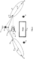
Figure 2 is an overhead view of the remote controlled tool carrier ofFigure 1 showing a first and second operator disposed on opposing sides of a building. -
Figure 3 is an overhead view of the remote controlled tool carrier shown inFigure 1 .Figure 3 illustrates the use of a signal transmitter positioned along a desired path of travel of the tool carrier. -
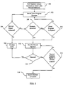
Figure 4 is a flow chart illustrating a process for exchanging control from a first remote control to a second remote control. -
Figure 5 is a flow chart illustrating a process for exchanging control between a firstremote control 12 and a secondremote control 14. The flow chart ofFigure 5 includes steps for autonomous movement of the tool carrier along a predetermined path. - Turning now to the figures and first to
Figure 1 , the general environment in which the apparatus and method of the present invention is used is illustrated.Figure 1 shows a system for controlling operation of a tool carrier generally indicated byreference numeral 10. The system comprises a firstremote control 12, a secondremote control 14, anantenna assembly 16 supported by thetool carrier 10, and acontroller system 18. The firstremote control 12 has at least oneuser input device 20 and is adapted to generate afirst control signal 22 in response to actuation of the user input device. The secondremote control 14 may be used by asecond operator 24 to generate asecond control signal 26 by actuation of a user input device. - As mentioned above, the
tool carrier 10 has anantenna assembly 16 adapted to receive thefirst control signal 22 and thesecond control signal 26 from the firstremote control 12 and the secondremote control 14, respectively. One skilled in the art will appreciate that there are a wide variety of receiving antennas appropriate for use in theantenna assembly 16 of the present invention. - The
controller system 18 is supported on the tool carrier and as will be discussed herein is adapted to control a wide variety oftool carrier 10 functions in response to thefirst control signal 22 and thesecond control signal 26. - Continuing with
Figure 1 , the first operator is shown carrying the firstremote control 12 having a plurality ofuser input devices 20. Suchuser input devices 20 may comprise manually operable knobs, buttons and joysticks and/or audio receiver supported on aportable frame 28. Theportable frame 28 can be worn or carried by thefirst operator 30. The firstremote control 12 may comprise a signal system having a signal generator (not shown). The signal generator of the firstremote control 12 is adapted to generate thefirst control signal 22. One skilled in the art will appreciate that several commercially available remote controls would be appropriate for the purpose of generating thecontrol signals controls antenna assembly 16 or for determining the location of the remote control relative to the tool carrier. Additionally, the remote control system may comprise a global positioning satellite ("GPS") receivingantenna 32 wearable by thefirst operator 30. TheGPS receiving antenna 32 may be used in cooperation with a tool carrierGPS receiving antenna 33 to determine the position of the firstremote control 12 relative to thetool carrier 10. - The
second operator 24 may also control operation of thetool carrier 10 using thesecond control signal 26 at thesecond location 34. The secondremote control 14 may also comprise aGPS receiving antenna 36 used in cooperation with the tool carrierGPS receiving antenna 33 and the first remote controlGPS receiving antenna 32 to determine the position of the remote controls relative to the tool carrier. - The
tool carrier 10 shown inFigure 1 may comprise a small loader with a track-laying undercarriage 38. Such a tool carrier is frequently utilized on construction and earthmoving work sites. The "tool carrier" classification implies that the tool carrier is adaptable to a variety of tasks throughinterchangeable work tools 40. Such atool carrier 10 may be controlled in response tocontrol signals remote control 12 and the secondremote control 14, respectively. For purposes of illustration, thework tool 40 shown inFigure 1 comprises a front-end loader bucket attachable to amovable arm 42 or other positioning mechanism. Other work tools may include trenchers, forks, a box blade or a backhoe. One skilled in the art will appreciate that a wide variety of machine types including skid steer loaders and tractors may be remotely controlled in accordance with the present invention. - The
tool carrier 10 may comprise theantenna assembly 16 and acontroller system 18. Theantenna assembly 16 is supported by thetool carrier 10 and adapted to receive thefirst control signal 22 from the firstremote control 12 and thesecond control signal 26 from the secondremote control 14. Theantenna assembly 16 may comprise a bi-directional communication system for communicating with both the firstremote control 12 and the secondremote control 14 and theGPS receiver 33. TheGPS receiver 33 is capable of receiving signals from a plurality ofGPS satellites 44. The first andsecond control signals antenna assembly 16 and processed by thecontroller system 18. Thecontroller system 18 controls operation of thetool carrier 10 in response to either or both thefirst control signal 22 and thesecond control signal 26 and as described later herein, to autonomously control movement of the tool carrier along a predetermined path. - The
tool carrier 10 may further comprise at least one obstacle avoidance sensor adapted to detect an obstacle disposed within or near the tool carrier's path of travel. Thetool carrier 10 may have a forwardobstacle avoidance sensor 46 to detect obstacles in front of the tool carrier and a rearobstacle avoidance sensor 48 to detect obstacles disposed behind the tool carrier. Theobstacle avoidance sensors - Turning now to
Figure 2 thetool carrier 10 is shown moving along afirst path 50 between afirst location 52 and a hand-offpoint 54. As shown inFigure 2 thefirst operator 30 may be positioned on the worksite on one side of a large obstruction such as abuilding 56. Thefirst operator 30 may be positioned to have a clear line ofsight 58 to thefirst location 52 and hand-offpoint 54. As used herein "hand-off point" may comprise any location where control of thetool carrier 10 may be transferred from the firstremote control 12 to the secondremote control 14 to control movement of the tool carrier along asecond path 64 between the hand-off point and thesecond location 34. - The
first operator 30 may control thetool carrier 10 within afirst work area 60. The first work area may comprise the area directly around thefirst location 52. However, as shown inFigure 2 , the first work area may extend to the hand-off point where it may overlap with thesecond work area 62. The effective range of the control signal generated by the appropriate remote control may define thefirst work zone 60 andsecond work zone 62. Alternatively, the work zones may be defined by the physical characteristics of the jobsite. For example, thesecond work zone 62 may have a boundary situated at a point where thetool carrier 10 returns to the second operator's line ofsight 66. However, one skilled in the art will appreciate that the shape and size of the work areas may vary considerably depending on the worksite and the presence of any buildings or obstacles without departing from the spirit of the present invention. - The
first location 52 is disposed within thefirst work zone 60 within which thefirst operator 30 has control of thetool carrier 10. Thesecond location 34 is disposed within thesecond work zone 62 within which thesecond operator 24 may have control of thetool carrier 10. In accordance with the present invention, the first andsecond operators controller system 18 is adapted to determine which remote control may have control of thetool carrier 10 based upon a variety of factors discussed herein including the position of the tool carrier relative to the remote control. - In operation, the
first control signal 22 may be selected by thecontroller system 18 when thetool carrier 10 is disposed at thefirst location 52 or within thefirst work zone 60. While present in thefirst work zone 60, thefirst operator 30 may control thetool carrier 10 with thefirst work signal 22 to perform a wide variety of activities such as excavating a jobsite or loading materials to be moved to another location. Thefirst operator 30 may then move thetool carrier 10 along thefirst path 50 to the hand-off point 54. At the hand-off point 54 thefirst control signal 22 may be deselected by thecontroller system 18 and thesecond control signal 26 selected by the controller system to allow control of thetool carrier 10 by the secondremote control 14 within thesecond work zone 62. In accordance with the present invention, thesecond control signal 26 may be selected by thecontroller system 18 to the exclusion of thefirst control signal 22 to reduce the likelihood of thefirst operator 30 interfering with operation of the tool carrier when the second operator has control. The system may also be adapted to require theoperator 30 to actively relinquish control of thetool carrier 10 by deselecting thefirst control signal 22 on the remote control at the hand-off point 54. - Turning now to
Figure 3 there is shown therein an alternative control system of the present invention wherein thetool carrier 10 is capable of autonomous movement between thefirst work zone 60 andsecond work zone 62. Thetool carrier 10 is shown positioned on apredetermined path 68 near which the tool carrier may autonomously move between thefirst work zone 60 and thesecond work zone 62. As illustrated inFigure 3 thecontroller system 18 of the present invention may further comprise asignal transmitter 70 positioned near thepredetermined path 68. Thesignal transmitter 70 is adapted to transmit a reference signal to thecontroller system 18 to establish a path relative to thetool carrier 10 and the signal transmitter along which the tool carrier is steered toward thesecond work zone 62. Alternatively, thesignal transmitter 70 may comprise a low-frequency beacon 72 adapted to transmit a homing signal to thecontroller system 18. Further, thesignal transmitter 70 may direct a laser beam to the tool carrier to guide the carrier along the desired path. - In operation, the
first operator 30 may use thetool carrier 10 within thefirst work zone 60 to complete a certain task. When thefirst operator 30 is finished with the task, the first operator may move thetool carrier 10 to a first hand-off point 54a. The first hand-off point 54a is shown inFigure 3 outside thefirst work zone 60. However, the first hand-off point 54a may be located at a wide variety of points including within thefirst work zone 60. Upon arrival at the first hand-off point 54a, thecontroller system 18 may be programmed to take control of thetool carrier 10 to autonomously move the tool carrier along thepredetermined path 68 to a second hand-off point 54b. Upon arrival at the second hand-off point 54b thesecond operator 24 may take control of thetool carrier 10 with the second remote control 14 (FIG. 1 ). When thesecond operator 24 is finished with the 10 tool carrier, the process may be reversed to move the tool carrier back to the first hand-off point 54a to give control back to thefirst operator 30. - In a preferred embodiment, the
controller system 18 may use the previously describedGPS receiving antenna 33 disposed on thetool carrier 10 to guide the tool carrier along thepredetermined path 68 between the first hand-off point 54a and the second hand-off point 54b. Thecontroller system 18 comprising theGPS receiving antenna 33 may be programmed to follow thepredetermined path 68 by moving thetool carrier 10 along the predetermined path under the control of either the firstremote control 12 or the secondremote control 14 and recording and storing several GPS coordinate measurements taken along the desired path. Thecontroller system 18 may then use the position measurements to autonomously move thetool carrier 10 between thefirst work zone 60 and thesecond work zone 62 as desired by the operators. - Alternatively, the
signal transmitter 70 may be stationed on the worksite to transmit a reference signal to thecontroller system 18 for establishing apath 74 along which thetool carrier 10 may be steered. The reference signal transmitted by thesignal transmitter 70 may comprise a radio-frequency signal or a laser beam directed to a laser beam receiver (not shown) supported on thetool carrier 10 and operatively connected to thecontroller system 18. The laser receiver andcontroller system 18 may be configured to steer thetool carrier 10 along a laser path (not shown) defined by the path of the laser beam received at the tool carrier. In such case, thecontroller system 18 could be adapted to move thetool carrier 10 in a variety of directions to maintain contact with the laser beam transmitted from thesignal transmitter 70. - It will be appreciated by one skilled in the art that a plurality of
signal transmitters 70 may be utilized on the work site to coordinate autonomous movement of thetool carrier 10 over extended distances or along a path comprising many turns. For example, the plurality ofsignal transmitters 70 may comprise the previously described GPS system adapted to coordinate movement of thetool carrier 10 between thefirst work zone 60 and thesecond work zone 62. - Referring now to
Figures 2 ,3 , and4 and by way of example only, thefirst work zone 60 may comprise the front yard of ahouse 56. Thefirst operator 30 may control the tool carrier 10 (Step 400) within thefirst work zone 60 to, for example, pickup a pallet of sod, then drive thetool carrier 10 to the hand-off point 54. At the hand-off point 54 thefirst operator 30 relinquishes control of thetool carrier 10. Relinquishing control of thetool carrier 10 may comprise sending a release signal (Step 402) from the firstremote control 12. At the hand-off point 54, thesecond operator 24 may notice that thetool carrier 10 has come into view and take control of thetool carrier 10 if he is within safe operating range of the tool carrier (Step 404). If thesecond operator 24 is not within safe operating range, an error condition may be indicated (Step 406) and control is returned to thefirst operator 30. If thesecond operator 24 is within a safe range and acknowledges he is ready to take control of the tool carrier (Step 408), the second operator is given control (Step 410) by thecontroller system 18. Once thesecond operator 24 has control, the tool carrier may be driven to thesecond work zone 62, where a work crew might be laying out the sod in the backyard of thehouse 56. - After the
second operator 24 completes his work in thesecond work zone 62 he may reverse the process by maneuvering thetool carrier 10 back to the hand-off point 54 and relinquish control of the tool carrier to thefirst operator 30. - In an alternative mode of operation, control of the
tool carrier 10 may be limited to one operator at any one time. In such case, thefirst operator 30 would purposefully relinquish control of thetool carrier 10 before thesecond operator 24 is allowed to take control of thetool carrier 10 with the secondremote control 14 and vice-a-versa. Accordingly, whichever operator has control of thetool carrier 10 will maintain control until purposefully relinquishing it to another operator by transmitting a relinquishment command from the remote control. For example, to pass control from the firstremote control 12 to the secondremote control 14, thefirst operator 30 may turn off aswitch 20 on the firstremote control 12 to release active control. Thesecond operator 24 may then activate asimilar switch 20 on the secondremote control 14 to gain control of thetool carrier 10 and would posses control until the switch on the second remote control was turned off. - Other methods to relinquish control could be envisioned, such as releasing an operator presence system on the
tool carrier 10. In such case the first operator to activate the operator presence switch on either the firstremote control 12 or secondremote control 14 would possess control of thetool carrier 10 until relinquished. - Alternatively, the
controller system 18 may be configured to make decisions regarding control of thetool carrier 10 based upon: the strength of the control signal received at theantenna assembly 16, the respective location of the firstremote control 12 and the secondremote control 14 relative to the tool carrier, or a preprogrammed set of parameters established so that thefirst control signal 22 has priority over thesecond control signal 26. Further, thecontroller system 18 may be configured to select both thefirst control signal 22 and thesecond control signal 26 when multiple operators are needed to control movement of thetool carrier 10 and operation of thework tool 40 at the same time. - Possessing control of the
tool carrier 10, as previously discussed, may comprise several steps and requirements before control is allowed. For example, if thefirst operator 30 is attempting to control thetool carrier 10 with the firstremote control 12, the tool carrier must recognize thefirst control signal 22 before operation of the tool carrier is allowed. - The
controller system 18 may be configured to allow or accept input from only one of the remote controllers at a time. Thus, thecontroller system 18 would reject or ignore signals from any and all other remote controls during operation, even those that at another time could be allowed to operate thetool carrier 10. However, thecontroller system 18 may be configured to accept an Emergency Stop or Shutdown signal from any or all remote controls regardless of which remote control is presently in control of thetool carrier 10. - The
first control signal 22 andsecond control signal 26 may each comprise a unique identifier used by thecontroller system 18 to identify the source of the control signal received by theantenna assembly 16. The unique identifier may comprise a specific frequency, that once established is the only frequency that can carry signals to operate thetool carrier 10. An alternate method could use a standard communication frequency that could include the unique identifier as part of each instruction packet communicated to thecontroller system 18. For example, when thefirst operator 30 has control of thetool carrier 10, control rests with the first operator until he purposefully relinquishes control and thecontroller system 18 would reject all other inputs not containing the unique identifier. - One skilled in the art will appreciate that when
certain tool carriers 10 are configured for specialized applications, such as trenching, it may be beneficial for the firstremote control 12 to serve as a primary controller adapted to take control of thetool carrier 10 from any secondary remote controls. Additionally, one skilled in the art can appreciated that thecontroller system 18 may be configured to allow shared control of the tool carrier for certain operations of the tool carrier. Such a configuration may be useful in instances where a single operator may have difficulty controlling bothground drive 38 andwork tool 40 functions. - If the
tool carrier 10 is adapted to determine the position of each operator relative to the tool carrier, other rules could be applied by thecontroller system 18 to manage operation of the tool carrier. For example, thecontroller system 18 may be programmed to stop function of thework tool 40 or stop movement of thetool carrier 10 where any unauthorized operator or work crew member enters either thefirst work zone 60 or thesecond work zone 62. For example, if thefirst operator 30 is operating thetool carrier 10 with a trencher attached and thesecond operator 24 enters into a predetermined exclusion zone or work zone, thecontroller system 18 may activate its prescribed response such as stopping work tool function or shutting down the tool carrier. - Continuing with
Figure 5 , thefirst operator 30 may move thetool carrier 10 to the first hand-off point 54a and initiate autonomous movement of the tool carrier to the second hand-off point 54b (Step 500). At this point, thefirst operator 30 could turn his focus to other tasks necessary around the vicinity of the worksite while waiting for the tool carrier to return. Thecontroller system 18 takes control of the tool carrier and executes the stored travel program (Step 502). As the tool carrier travels thepredetermined path 68, the operators may have the ability to issue an emergency stop signal (Step 504) to thecontroller system 18. If an emergency stop signal is detected by thecontroller system 18 operation of thetool carrier 10 may be halted (Step 506). - If no emergency stop signal is detected the tool carrier may continue along the
predetermined path 68.Obstacle avoidance sensors predetermined path 68. If an obstacle is detected bysensors controller system 18 may halt movement of the tool carrier (Step 506) or alter thepredetermined path 68 to avoid the obstacle and proceed to the pre-programmed destination point. In the event that no obstacles are detected or the path altered to avoid any obstacles, the tool carrier will continue its travel program. Execution of the stored travel program will continue until completed by arrival of thetool carrier 10 at the second hand-off point 54b (Step 510). - Autonomous movement of the
tool carrier 10 long thepredetermined path 68 could be controlled in several different ways. Ifsignal transmitters 70 are placed along thepath 68, then thetool carrier 10 would use them as reference points as it travels along the predetermined path. Since thetool carrier 10 could discern its position relative to these fixedsignal transmitters 70, it could follow a path relative to these positions. Alternatively, the previously described GPS, laser based system or other could be used to provide adequate location information for autonomous operations. For most of the autonomous operations described herein, very fine positioning is not required and thetool carrier 10 may simply travel an approximate path betweenpoints - Upon arrival at the second hand-
off point 54b, thetool carrier 10 will wait for thesecond operator 24 to take control (Step 512). Thecontroller system 18 may provide the second operator a certain interval of time to take control of the tool carrier 10 (Step 514) or the tool carrier will be halted (Step 506). If thesecond operator 24 transmits the second control signal 26 (Step 516) before time expires the second operator may then have control of the tool carrier (Step 518) until the second operator actively relinquishes control or control is taken by a dominant control signal. - The
tool carrier 10 may posses a learn mode of operation. The purpose of the learn mode is to teach or store in memory thepredetermined path 68 such that thetool carrier 10 could repeat that path as needed. The computer program within thecontroller system 18 would control this process. As discussed previously herein, one way to accomplish this path storage is to enable a learn mode within thetool carrier 10 and then physically and manually drive the tool carrier along the desired path, storing positional and operational information along the way. Depending on complexity of the learn mode, one could envision programming thecontroller system 18 to change engine speed, valve displacements, attachment positions, ground drive speeds, orientation and directions, etc. based upon the position of the tool carrier along thepredetermined path 68. Although only onetool carrier 10 is used in the previous example, one could envision two or more tool carriers being used simultaneously. - In an alternative embodiment the
predetermined path 68 may comprise a preprogrammed path for thetool carrier 10 to follow for testing. In this case thetool carrier 10 would be trained to travel a continuous path, generally in a closed shape such as a circle. Thetool carrier 10 would travel the same route over and over again and correct back to path if it is perturbed from its predefined path. Thetool carrier 10 would continue to operate in this fashion until a fixed number of cycles or time was reached. Thecontroller system 18 would likely have a pre-programmed interruption mechanism for stopping the test prematurely and would have fixed limits on path deviation such that if exceeded would stop the test and await further instruction. This testing could also include elements where operating conditions of the tool carrier such as engine temperature could be monitored and if exceeded, the test would halt. Also one could envision any number of ways to monitor the test and allow a test technician to control and modify as necessary. In some situations, the test could be continuously monitored such that an operator is required only to maintain an enable mode at the remote control to allow thetool carrier 10 to operate. - A third variation is for the situation where the
tool carrier 10 is operating in the same manner for an extended period of time while following the predetermined path. This would be the case for a trencher or rock saw operating very slowly. In this case thetool carrier 10 would be set up and operations started. Once steady operation was achieved the operator would initiate a "cruise" control option to allow thetool carrier 10 to continue operation for as long as the operator transmits an enable signal from the remote control. During operation small changes in operation could be initiated to optimize operation. Once thetool carrier 10 nears its destination the operator can take over full control of thetool carrier 10 to finalize the operation. Certainly combinations of the above concepts could also apply. - Various modifications can be made in the design and operation of the present invention. Thus, while the principal preferred construction and modes of operation of the invention have been explained in what is now considered to represent its best embodiments, which have been illustrated and described, it should be understood that within the scope of the appended claims, the invention may be practiced otherwise than as specifically illustrated and described.
Claims (27)
- A system for controlling operation of a tool carrier (10), the system comprising a first remote control (12) adapted to generate a first control signal (22), a second remote control (14) adapted to generate a second control signal (26), and a controller system (18) supported on the tool carrier (10) characterized in that:the controller system (18) is adapted to select and receive the first control signal (22) when the tool carrier (10) is at a first work zone (60) to the exclusion of the second control signal (26) and to select and receive the second control signal (26) when the tool carrier is at a second work zone (62) to the exclusion of the first control signal (22) to control operation of the tool carrier (10).
- The system of claim 1 wherein the controller system (18) is further adapted to autonomously control movement of the tool carrier (10) along a predetermined path (68) between the first work zone (60 and the second work zone (62).
- The system of claim 2 further comprising a signal transmitter (70) positioned along the predetermined path (68); wherein the signal transmitter (70) is adapted to transmit a reference signal to the controller system (18) for establishing a path (68) relative to the tool carrier (10) and the signal transmitter (70) along which the tool carrier (10) is steered toward the second work zone (62).
- The system of claim 1 wherein the controller system (18) comprises a global positioning system (33).
- The system of claim 4 wherein the global positioning system (33) is adapted to guide the tool carrier (10) along a path (68) between the first work zone (60) and the second work zone (62).
- The system of claim 4 wherein the controller system (18) is adapted to select either the first control signal (22) or the second control signal (26) based on the location of the tool carrier (10) determined using the global positioning system (33).
- The system of claim 1 wherein the tool carrier (10) comprises an obstacle avoidance system (46, 48) adapted to detect an obstacle to tool carrier operation.
- The system of claim 7 wherein the obstacle avoidance system (46, 48) comprises an acoustic sensor system.
- The system of claim 1 wherein the first control signal (22) comprises a first remote control relinquishment command.
- The system of claim 1 wherein both the first remote control (12) and the second remote control (14) are further adapted to transmit a shutdown command signal to the controller system (18) to shutdown operation of tool carrier (10) regardless of selection of the first control signal (22) or the second control signal (26) by the controller system (18).
- The system of claim 1 wherein the first control signal (22) comprises a first unique identifier.
- The system of claim 11 wherein the first unique identifier comprises a frequency specific to only the first remote control (12).
- The system of claim 1 wherein the tool carrier (10) comprises a work tool (40) operatively connected to the tool carrier (10) and wherein the controller system (18) is adapted to autonomously control operation of the tool carrier (10) and the work tool (40) along a predetermined path (68).
- The system of claim 1 further comprising a plurality of signal transmitters (70), wherein the signal transmitters (70) are each adapted to transmit a positioning signal to the controller system (18) for establishing a path (74) along which the tool carrier (10) is steered.
- The system of claim 14 wherein the plurality of signal transmitters (70) each comprise a global positioning system.
- The system of claim 15 wherein the positioning signal transmitted by each of the plurality of signal transmitters (70) comprises a laser beam.
- The system of claim 1 wherein the controller system (18) is adapted to record movement of the tool carrier (10) along a path (68,74) and to autonomously move the tool carrier (10) along the recorded path.
- The system of claim 1 wherein the first control signal (22) comprises an enable signal adapted to enable autonomous control of the tool carrier (10) by the controller system (18).
- A method for controlling operation of a tool carrier (10), the method comprising transmitting a first control signal (22) from a first remote control (12) and transmitting a second control signal (26) from a second remote control (14), the method characterized in that:the first control signal (22) is selected when the tool carrier (10) is at a first work zone (60) to the exclusion of the second control signal (26); andthe second control signal (26) is selected when the tool carrier (10) is at a second work zone to the exclusion of the first control signal (22) to control operation of the tool carrier (10).
- The method of claim 19 further comprising autonomously moving the tool carrier (10) along a path (68) between a first hand-off point (54a) and a second hand-off point (54b).
- The method of claim 19 further comprising:moving the tool carrier (10) along a path (68) between a first hand-off point (54a) and a second hand-off point (54b);recording movements of the tool carrier (10) along the path (68); andautonomously moving the tool carrier (10) along the path (68) using the recorded movements.
- The method of claim 21 further comprising automatically altering the path (68) to avoid an obstacle disposed within the path.
- The method of claim 22 wherein autonomously moving the tool carrier (10) along the path (68) further comprises:transmitting a positioning signal to the tool carrier (10) to establish a path (68, 74) between the tool carrier (10) and a point located along the path; andsteering the tool carrier (10) toward the point located along the path (68, 74).
- The method of claim 19 wherein moving the tool carrier (10) to the second work zone (62) comprises positioning the tool carrier (10) at a hand-off point (54) and selecting the disabled control signal to take control of the tool carrier (10).
- The method of claim 19 further comprising:moving the tool carrier (10) to a first hand-off point (54a);autonomously moving the tool carrier (10) from the first hand-off point (54a) to a second hand-off point (54b);selecting the second control signal (26) when the tool carrier (10) is at the second hand-off point (54b); andoperating the tool carrier (10) at the second work zone (62) in response to the second control signal (26).
- The method of claim 19 further comprising transmitting a shutdown signal from either the first remote control (12) or the second remote control (14).
- The method of claim 19 wherein selecting the first control signal (22) comprises receiving a unique identifier carried by the first control signal (22).
Applications Claiming Priority (3)
| Application Number | Priority Date | Filing Date | Title |
|---|---|---|---|
| US69419305P | 2005-06-27 | 2005-06-27 | |
| US69428505P | 2005-06-27 | 2005-06-27 | |
| PCT/US2006/024998 WO2007002675A2 (en) | 2005-06-27 | 2006-06-27 | Remote control machine with partial or total autonomous control |
Publications (2)
| Publication Number | Publication Date |
|---|---|
| EP1907636A2 EP1907636A2 (en) | 2008-04-09 |
| EP1907636B1 true EP1907636B1 (en) | 2018-03-07 |
Family
ID=37110374
Family Applications (1)
| Application Number | Title | Priority Date | Filing Date |
|---|---|---|---|
| EP06774113.2A Not-in-force EP1907636B1 (en) | 2005-06-27 | 2006-06-27 | Remote control machine with partial or total autonomous control |
Country Status (3)
| Country | Link |
|---|---|
| US (1) | US8457828B2 (en) |
| EP (1) | EP1907636B1 (en) |
| WO (1) | WO2007002675A2 (en) |
Families Citing this family (34)
| Publication number | Priority date | Publication date | Assignee | Title |
|---|---|---|---|---|
| DE102007018646A1 (en) * | 2007-04-19 | 2008-10-30 | Liebherr-Werk Nenzing Gmbh | A method of controlling a load moving device and controlling a load moving device |
| US7676967B2 (en) * | 2007-04-30 | 2010-03-16 | Caterpillar Inc. | Machine with automated blade positioning system |
| US20100106344A1 (en) * | 2008-10-27 | 2010-04-29 | Edwards Dean B | Unmanned land vehicle having universal interfaces for attachments and autonomous operation capabilities and method of operation thereof |
| DE102010014902B4 (en) * | 2009-04-23 | 2019-02-07 | Bomag Gmbh | Multipurpose compactor and method of operating the multipurpose compactor |
| FR2954560B1 (en) * | 2009-12-23 | 2018-11-02 | Saml | WORKING AREA SECURING DEVICE |
| US8924067B2 (en) * | 2010-10-12 | 2014-12-30 | Caterpillar Inc. | Autonomous machine control system |
| US20120089291A1 (en) * | 2010-10-12 | 2012-04-12 | Halder Bibhrajit | Autonomous machine control system |
| US9324197B2 (en) * | 2011-03-11 | 2016-04-26 | Intelligent Agricultural Soultions | Method and system for managing the hand-off between control terminals |
| US10318138B2 (en) | 2011-03-11 | 2019-06-11 | Intelligent Agricultural Solutions Llc | Harvesting machine capable of automatic adjustment |
| US9474208B2 (en) | 2011-11-15 | 2016-10-25 | Appareo Systems, Llc | System and method for determining material yield and/or loss from a harvesting machine using acoustic sensors |
| US9631964B2 (en) | 2011-03-11 | 2017-04-25 | Intelligent Agricultural Solutions, Llc | Acoustic material flow sensor |
| US9629308B2 (en) | 2011-03-11 | 2017-04-25 | Intelligent Agricultural Solutions, Llc | Harvesting machine capable of automatic adjustment |
| US10321624B2 (en) | 2011-03-11 | 2019-06-18 | Intelligent Agriculture Solutions LLC | Air seeder manifold system |
| US9330062B2 (en) | 2011-03-11 | 2016-05-03 | Intelligent Agricultural Solutions, Llc | Vehicle control and gateway module |
| US20160246296A1 (en) * | 2011-03-11 | 2016-08-25 | Intelligent Agricultural Solutions, Llc | Gateway system and method |
| US9116787B1 (en) * | 2012-06-27 | 2015-08-25 | Marden Industries, Inc. | Electronic control system for mobile heavy equipment machinery |
| RU2014131944A (en) | 2013-08-02 | 2016-02-20 | Вермир Мэньюфэкчеринг Компэни | REMOTE CONTROL SYSTEM (OPTIONS) AND REMOTE CONTROL METHOD |
| US9650062B2 (en) | 2013-08-26 | 2017-05-16 | Wacker Neuson Production Americas Llc | System for controlling remote operation of ground working devices |
| JP6093278B2 (en) * | 2013-09-30 | 2017-03-08 | 株式会社クボタ | Wireless communication system |
| EP2957679B1 (en) * | 2014-06-18 | 2018-12-26 | Morath GmbH | Superordinate control system |
| JP6492456B2 (en) * | 2014-08-19 | 2019-04-03 | 井関農機株式会社 | Operation system |
| US10085379B2 (en) | 2014-09-12 | 2018-10-02 | Appareo Systems, Llc | Grain quality sensor |
| US10047500B2 (en) | 2014-11-07 | 2018-08-14 | Wacker Neuson Production Americas Llc | Remote controlled compaction machine |
| CN105589459B (en) * | 2015-05-19 | 2019-07-12 | 中国人民解放军国防科学技术大学 | The semi-autonomous remote control method of unmanned vehicle |
| US10719289B2 (en) * | 2015-11-05 | 2020-07-21 | Topcon Positioning Systems, Inc. | Monitoring and control display system and method using multiple displays in a work environment |
| DK3398022T3 (en) * | 2016-02-26 | 2021-02-01 | Sz Dji Technology Co Ltd | SYSTEMS AND METHODS FOR CUSTOMIZING UAV-TRACK |
| JP6913343B2 (en) * | 2017-03-22 | 2021-08-04 | コーワテック株式会社 | Stop device |
| US10782665B2 (en) | 2017-06-30 | 2020-09-22 | Cattron North America, Inc. | Wireless emergency stop systems, and corresponding methods of operating a wireless emergency stop system for a machine safety interface |
| JP6399669B1 (en) * | 2017-07-28 | 2018-10-03 | 三菱ロジスネクスト株式会社 | Driving support system and driving support method |
| US11162241B2 (en) * | 2018-03-27 | 2021-11-02 | Deere & Company | Controlling mobile machines with a robotic attachment |
| WO2019189320A1 (en) * | 2018-03-28 | 2019-10-03 | 株式会社タダノ | Work vehicle |
| US10883256B2 (en) | 2018-05-25 | 2021-01-05 | Deere & Company | Object responsive control system for a work machine |
| WO2021021943A1 (en) | 2019-07-29 | 2021-02-04 | Great Plains Manufacturing, Inc. | Compact utility loader |
| US11487263B2 (en) | 2020-01-24 | 2022-11-01 | Cattron North America, Inc. | Wireless emergency stop systems including mobile device controllers linked with safety stop devices |
Family Cites Families (14)
| Publication number | Priority date | Publication date | Assignee | Title |
|---|---|---|---|---|
| US3639755A (en) * | 1970-01-02 | 1972-02-01 | Gen Signal Corp | Remote control of a locomotive |
| US5672044A (en) * | 1974-01-24 | 1997-09-30 | Lemelson; Jerome H. | Free-traveling manipulator with powered tools |
| US5006988A (en) * | 1989-04-28 | 1991-04-09 | University Of Michigan | Obstacle-avoiding navigation system |
| FI942218A0 (en) * | 1994-05-13 | 1994-05-13 | Modulaire Oy | Automatic storage system Foer obemannat fordon |
| US5448479A (en) * | 1994-09-01 | 1995-09-05 | Caterpillar Inc. | Remote control system and method for an autonomous vehicle |
| DE19731749A1 (en) | 1997-07-23 | 1999-03-11 | Duschek Horst Juergen Dipl Ing | Method of monitoring an unmanned vehicle or drone |
| JPH11165981A (en) | 1997-12-05 | 1999-06-22 | Matsushita Electric Ind Co Ltd | Radio controller for crane |
| US6263989B1 (en) * | 1998-03-27 | 2001-07-24 | Irobot Corporation | Robotic platform |
| US6052181A (en) * | 1998-07-01 | 2000-04-18 | Trimble Navigation Limited | Multiple simultaneous laser-reference control system for construction equipment |
| US6324455B1 (en) * | 1998-11-05 | 2001-11-27 | Trimble Navigation Ltd | Laser level selection |
| EP1452651A1 (en) * | 2001-06-20 | 2004-09-01 | Hitachi Construction Machinery Co., Ltd. | Remote control system and remote setting system of construction machinery |
| US6925357B2 (en) * | 2002-07-25 | 2005-08-02 | Intouch Health, Inc. | Medical tele-robotic system |
| US7792089B2 (en) * | 2002-07-31 | 2010-09-07 | Cattron-Theimeg, Inc. | System and method for wireless remote control of locomotives |
| US7251491B2 (en) * | 2003-07-31 | 2007-07-31 | Qualcomm Incorporated | System of and method for using position, velocity, or direction of motion estimates to support handover decisions |
-
2006
- 2006-06-27 US US11/994,034 patent/US8457828B2/en active Active
- 2006-06-27 WO PCT/US2006/024998 patent/WO2007002675A2/en active Application Filing
- 2006-06-27 EP EP06774113.2A patent/EP1907636B1/en not_active Not-in-force
Also Published As
| Publication number | Publication date |
|---|---|
| US8457828B2 (en) | 2013-06-04 |
| EP1907636A2 (en) | 2008-04-09 |
| US20080208395A1 (en) | 2008-08-28 |
| WO2007002675A2 (en) | 2007-01-04 |
| WO2007002675A3 (en) | 2007-04-26 |
Similar Documents
| Publication | Publication Date | Title |
|---|---|---|
| EP1907636B1 (en) | Remote control machine with partial or total autonomous control | |
| EP1462899B1 (en) | System and method for controlling a vehicle having multiple control modes | |
| AU2016200300B2 (en) | Control system having tool tracking | |
| CA2792960C (en) | Driving system of unmanned vehicle and driving path generation method | |
| US9605409B2 (en) | System and method for operating a machine | |
| AU2017375792B2 (en) | Asset tracking and work tool identification | |
| JP7236887B2 (en) | Route generation system | |
| CN106462165A (en) | Work vehicle and travel control device for automatic travel of work vehicle | |
| WO1996030815A1 (en) | Method and device for preparing running course data for an unmanned dump truck | |
| CN103299004A (en) | System for autonomous path planning and machine control | |
| JPH05119835A (en) | Robot device | |
| JP7108499B2 (en) | automatic driving system | |
| KR20220061596A (en) | Excavator having a remote control function and operation method thereof | |
| EP3994538A1 (en) | Intelligent system for autonomous navigation | |
| US20200363808A1 (en) | Retrotraverse of Autonomous Vehicles without Pinning or with Automatic Pinning | |
| JP3712249B2 (en) | Autonomous traveling vehicle having lifting work machine and teaching method for lifting control of work machine | |
| KR102423054B1 (en) | Autonomous driving method and dozer using the same | |
| US20230266145A1 (en) | Autonomous vehicle with automated following of person outside vehicle | |
| JP7068969B2 (en) | Autonomous driving system | |
| CA3139501A1 (en) | Localized navigation system controller for power machine | |
| WO2024061460A1 (en) | Method and system for controlling movement of an autonomous load-carrier vehicle | |
| KR20230141449A (en) | Automatic traveling method, automatic traveling system, and automatic traveling program | |
| KR20220001777A (en) | Autonomous working construction machinery and operation method thereof | |
| KR20230124172A (en) | Construction machinary and user login method using the same |
Legal Events
| Date | Code | Title | Description |
|---|---|---|---|
| PUAI | Public reference made under article 153(3) epc to a published international application that has entered the european phase |
Free format text: ORIGINAL CODE: 0009012 |
|
| 17P | Request for examination filed |
Effective date: 20071025 |
|
| AK | Designated contracting states |
Kind code of ref document: A2 Designated state(s): AT BE BG CH CY CZ DE DK EE ES FI FR GB GR HU IE IS IT LI LT LU LV MC NL PL PT RO SE SI SK TR |
|
| DAX | Request for extension of the european patent (deleted) | ||
| 17Q | First examination report despatched |
Effective date: 20100401 |
|
| GRAP | Despatch of communication of intention to grant a patent |
Free format text: ORIGINAL CODE: EPIDOSNIGR1 |
|
| INTG | Intention to grant announced |
Effective date: 20171002 |
|
| GRAS | Grant fee paid |
Free format text: ORIGINAL CODE: EPIDOSNIGR3 |
|
| GRAA | (expected) grant |
Free format text: ORIGINAL CODE: 0009210 |
|
| AK | Designated contracting states |
Kind code of ref document: B1 Designated state(s): AT BE BG CH CY CZ DE DK EE ES FI FR GB GR HU IE IS IT LI LT LU LV MC NL PL PT RO SE SI SK TR |
|
| REG | Reference to a national code |
Ref country code: GB Ref legal event code: FG4D |
|
| REG | Reference to a national code |
Ref country code: CH Ref legal event code: EP Ref country code: AT Ref legal event code: REF Ref document number: 976701 Country of ref document: AT Kind code of ref document: T Effective date: 20180315 |
|
| REG | Reference to a national code |
Ref country code: IE Ref legal event code: FG4D |
|
| REG | Reference to a national code |
Ref country code: DE Ref legal event code: R096 Ref document number: 602006054878 Country of ref document: DE |
|
| REG | Reference to a national code |
Ref country code: NL Ref legal event code: MP Effective date: 20180307 |
|
| REG | Reference to a national code |
Ref country code: LT Ref legal event code: MG4D |
|
| PG25 | Lapsed in a contracting state [announced via postgrant information from national office to epo] |
Ref country code: ES Free format text: LAPSE BECAUSE OF FAILURE TO SUBMIT A TRANSLATION OF THE DESCRIPTION OR TO PAY THE FEE WITHIN THE PRESCRIBED TIME-LIMIT Effective date: 20180307 Ref country code: CY Free format text: LAPSE BECAUSE OF FAILURE TO SUBMIT A TRANSLATION OF THE DESCRIPTION OR TO PAY THE FEE WITHIN THE PRESCRIBED TIME-LIMIT Effective date: 20180307 Ref country code: LT Free format text: LAPSE BECAUSE OF FAILURE TO SUBMIT A TRANSLATION OF THE DESCRIPTION OR TO PAY THE FEE WITHIN THE PRESCRIBED TIME-LIMIT Effective date: 20180307 Ref country code: FI Free format text: LAPSE BECAUSE OF FAILURE TO SUBMIT A TRANSLATION OF THE DESCRIPTION OR TO PAY THE FEE WITHIN THE PRESCRIBED TIME-LIMIT Effective date: 20180307 |
|
| REG | Reference to a national code |
Ref country code: AT Ref legal event code: MK05 Ref document number: 976701 Country of ref document: AT Kind code of ref document: T Effective date: 20180307 |
|
| PG25 | Lapsed in a contracting state [announced via postgrant information from national office to epo] |
Ref country code: GR Free format text: LAPSE BECAUSE OF FAILURE TO SUBMIT A TRANSLATION OF THE DESCRIPTION OR TO PAY THE FEE WITHIN THE PRESCRIBED TIME-LIMIT Effective date: 20180608 Ref country code: BG Free format text: LAPSE BECAUSE OF FAILURE TO SUBMIT A TRANSLATION OF THE DESCRIPTION OR TO PAY THE FEE WITHIN THE PRESCRIBED TIME-LIMIT Effective date: 20180607 Ref country code: SE Free format text: LAPSE BECAUSE OF FAILURE TO SUBMIT A TRANSLATION OF THE DESCRIPTION OR TO PAY THE FEE WITHIN THE PRESCRIBED TIME-LIMIT Effective date: 20180307 Ref country code: LV Free format text: LAPSE BECAUSE OF FAILURE TO SUBMIT A TRANSLATION OF THE DESCRIPTION OR TO PAY THE FEE WITHIN THE PRESCRIBED TIME-LIMIT Effective date: 20180307 |
|
| PG25 | Lapsed in a contracting state [announced via postgrant information from national office to epo] |
Ref country code: RO Free format text: LAPSE BECAUSE OF FAILURE TO SUBMIT A TRANSLATION OF THE DESCRIPTION OR TO PAY THE FEE WITHIN THE PRESCRIBED TIME-LIMIT Effective date: 20180307 Ref country code: PL Free format text: LAPSE BECAUSE OF FAILURE TO SUBMIT A TRANSLATION OF THE DESCRIPTION OR TO PAY THE FEE WITHIN THE PRESCRIBED TIME-LIMIT Effective date: 20180307 Ref country code: NL Free format text: LAPSE BECAUSE OF FAILURE TO SUBMIT A TRANSLATION OF THE DESCRIPTION OR TO PAY THE FEE WITHIN THE PRESCRIBED TIME-LIMIT Effective date: 20180307 Ref country code: EE Free format text: LAPSE BECAUSE OF FAILURE TO SUBMIT A TRANSLATION OF THE DESCRIPTION OR TO PAY THE FEE WITHIN THE PRESCRIBED TIME-LIMIT Effective date: 20180307 |
|
| PGFP | Annual fee paid to national office [announced via postgrant information from national office to epo] |
Ref country code: IT Payment date: 20180625 Year of fee payment: 13 |
|
| PG25 | Lapsed in a contracting state [announced via postgrant information from national office to epo] |
Ref country code: AT Free format text: LAPSE BECAUSE OF FAILURE TO SUBMIT A TRANSLATION OF THE DESCRIPTION OR TO PAY THE FEE WITHIN THE PRESCRIBED TIME-LIMIT Effective date: 20180307 Ref country code: CZ Free format text: LAPSE BECAUSE OF FAILURE TO SUBMIT A TRANSLATION OF THE DESCRIPTION OR TO PAY THE FEE WITHIN THE PRESCRIBED TIME-LIMIT Effective date: 20180307 Ref country code: SK Free format text: LAPSE BECAUSE OF FAILURE TO SUBMIT A TRANSLATION OF THE DESCRIPTION OR TO PAY THE FEE WITHIN THE PRESCRIBED TIME-LIMIT Effective date: 20180307 |
|
| REG | Reference to a national code |
Ref country code: DE Ref legal event code: R097 Ref document number: 602006054878 Country of ref document: DE |
|
| PG25 | Lapsed in a contracting state [announced via postgrant information from national office to epo] |
Ref country code: PT Free format text: LAPSE BECAUSE OF FAILURE TO SUBMIT A TRANSLATION OF THE DESCRIPTION OR TO PAY THE FEE WITHIN THE PRESCRIBED TIME-LIMIT Effective date: 20180709 |
|
| PLBE | No opposition filed within time limit |
Free format text: ORIGINAL CODE: 0009261 |
|
| STAA | Information on the status of an ep patent application or granted ep patent |
Free format text: STATUS: NO OPPOSITION FILED WITHIN TIME LIMIT |
|
| PG25 | Lapsed in a contracting state [announced via postgrant information from national office to epo] |
Ref country code: DK Free format text: LAPSE BECAUSE OF FAILURE TO SUBMIT A TRANSLATION OF THE DESCRIPTION OR TO PAY THE FEE WITHIN THE PRESCRIBED TIME-LIMIT Effective date: 20180307 |
|
| REG | Reference to a national code |
Ref country code: CH Ref legal event code: PL |
|
| 26N | No opposition filed |
Effective date: 20181210 |
|
| PG25 | Lapsed in a contracting state [announced via postgrant information from national office to epo] |
Ref country code: SI Free format text: LAPSE BECAUSE OF FAILURE TO SUBMIT A TRANSLATION OF THE DESCRIPTION OR TO PAY THE FEE WITHIN THE PRESCRIBED TIME-LIMIT Effective date: 20180307 |
|
| REG | Reference to a national code |
Ref country code: BE Ref legal event code: MM Effective date: 20180630 |
|
| PG25 | Lapsed in a contracting state [announced via postgrant information from national office to epo] |
Ref country code: LU Free format text: LAPSE BECAUSE OF NON-PAYMENT OF DUE FEES Effective date: 20180627 Ref country code: MC Free format text: LAPSE BECAUSE OF FAILURE TO SUBMIT A TRANSLATION OF THE DESCRIPTION OR TO PAY THE FEE WITHIN THE PRESCRIBED TIME-LIMIT Effective date: 20180307 |
|
| REG | Reference to a national code |
Ref country code: IE Ref legal event code: MM4A |
|
| PG25 | Lapsed in a contracting state [announced via postgrant information from national office to epo] |
Ref country code: LI Free format text: LAPSE BECAUSE OF NON-PAYMENT OF DUE FEES Effective date: 20180630 Ref country code: CH Free format text: LAPSE BECAUSE OF NON-PAYMENT OF DUE FEES Effective date: 20180630 Ref country code: FR Free format text: LAPSE BECAUSE OF NON-PAYMENT OF DUE FEES Effective date: 20180630 Ref country code: IE Free format text: LAPSE BECAUSE OF NON-PAYMENT OF DUE FEES Effective date: 20180627 |
|
| PG25 | Lapsed in a contracting state [announced via postgrant information from national office to epo] |
Ref country code: BE Free format text: LAPSE BECAUSE OF NON-PAYMENT OF DUE FEES Effective date: 20180630 |
|
| PG25 | Lapsed in a contracting state [announced via postgrant information from national office to epo] |
Ref country code: TR Free format text: LAPSE BECAUSE OF FAILURE TO SUBMIT A TRANSLATION OF THE DESCRIPTION OR TO PAY THE FEE WITHIN THE PRESCRIBED TIME-LIMIT Effective date: 20180307 |
|
| PG25 | Lapsed in a contracting state [announced via postgrant information from national office to epo] |
Ref country code: IT Free format text: LAPSE BECAUSE OF NON-PAYMENT OF DUE FEES Effective date: 20190627 |
|
| PG25 | Lapsed in a contracting state [announced via postgrant information from national office to epo] |
Ref country code: HU Free format text: LAPSE BECAUSE OF FAILURE TO SUBMIT A TRANSLATION OF THE DESCRIPTION OR TO PAY THE FEE WITHIN THE PRESCRIBED TIME-LIMIT; INVALID AB INITIO Effective date: 20060627 |
|
| PG25 | Lapsed in a contracting state [announced via postgrant information from national office to epo] |
Ref country code: IS Free format text: LAPSE BECAUSE OF FAILURE TO SUBMIT A TRANSLATION OF THE DESCRIPTION OR TO PAY THE FEE WITHIN THE PRESCRIBED TIME-LIMIT Effective date: 20180707 |
|
| PGFP | Annual fee paid to national office [announced via postgrant information from national office to epo] |
Ref country code: DE Payment date: 20200617 Year of fee payment: 15 |
|
| PGFP | Annual fee paid to national office [announced via postgrant information from national office to epo] |
Ref country code: GB Payment date: 20200618 Year of fee payment: 15 |
|
| REG | Reference to a national code |
Ref country code: DE Ref legal event code: R119 Ref document number: 602006054878 Country of ref document: DE |
|
| GBPC | Gb: european patent ceased through non-payment of renewal fee |
Effective date: 20210627 |
|
| PG25 | Lapsed in a contracting state [announced via postgrant information from national office to epo] |
Ref country code: GB Free format text: LAPSE BECAUSE OF NON-PAYMENT OF DUE FEES Effective date: 20210627 Ref country code: DE Free format text: LAPSE BECAUSE OF NON-PAYMENT OF DUE FEES Effective date: 20220101 |