EP1906504B1 - Protection arrangement of an electric motor - Google Patents
Protection arrangement of an electric motor Download PDFInfo
- Publication number
- EP1906504B1 EP1906504B1 EP07075785.1A EP07075785A EP1906504B1 EP 1906504 B1 EP1906504 B1 EP 1906504B1 EP 07075785 A EP07075785 A EP 07075785A EP 1906504 B1 EP1906504 B1 EP 1906504B1
- Authority
- EP
- European Patent Office
- Prior art keywords
- frequency converter
- circuit
- safety circuit
- thermistor
- motor
- Prior art date
- Legal status (The legal status is an assumption and is not a legal conclusion. Google has not performed a legal analysis and makes no representation as to the accuracy of the status listed.)
- Revoked
Links
- 238000001514 detection method Methods 0.000 claims description 6
- 238000012544 monitoring process Methods 0.000 claims description 3
- 239000004065 semiconductor Substances 0.000 claims description 3
- 230000002265 prevention Effects 0.000 claims description 2
- 238000013021 overheating Methods 0.000 description 6
- 230000033228 biological regulation Effects 0.000 description 3
- 238000004880 explosion Methods 0.000 description 3
- 241000555745 Sciuridae Species 0.000 description 2
- 238000005516 engineering process Methods 0.000 description 2
- 230000006698 induction Effects 0.000 description 2
- 238000000034 method Methods 0.000 description 2
- 230000001105 regulatory effect Effects 0.000 description 2
- 230000003213 activating effect Effects 0.000 description 1
- 230000001276 controlling effect Effects 0.000 description 1
- 230000000694 effects Effects 0.000 description 1
- 230000005611 electricity Effects 0.000 description 1
- 239000002360 explosive Substances 0.000 description 1
Images
Classifications
-
- H—ELECTRICITY
- H02—GENERATION; CONVERSION OR DISTRIBUTION OF ELECTRIC POWER
- H02K—DYNAMO-ELECTRIC MACHINES
- H02K11/00—Structural association of dynamo-electric machines with electric components or with devices for shielding, monitoring or protection
- H02K11/20—Structural association of dynamo-electric machines with electric components or with devices for shielding, monitoring or protection for measuring, monitoring, testing, protecting or switching
- H02K11/25—Devices for sensing temperature, or actuated thereby
-
- H—ELECTRICITY
- H02—GENERATION; CONVERSION OR DISTRIBUTION OF ELECTRIC POWER
- H02H—EMERGENCY PROTECTIVE CIRCUIT ARRANGEMENTS
- H02H7/00—Emergency protective circuit arrangements specially adapted for specific types of electric machines or apparatus or for sectionalised protection of cable or line systems, and effecting automatic switching in the event of an undesired change from normal working conditions
- H02H7/08—Emergency protective circuit arrangements specially adapted for specific types of electric machines or apparatus or for sectionalised protection of cable or line systems, and effecting automatic switching in the event of an undesired change from normal working conditions for dynamo-electric motors
- H02H7/085—Emergency protective circuit arrangements specially adapted for specific types of electric machines or apparatus or for sectionalised protection of cable or line systems, and effecting automatic switching in the event of an undesired change from normal working conditions for dynamo-electric motors against excessive load
- H02H7/0852—Emergency protective circuit arrangements specially adapted for specific types of electric machines or apparatus or for sectionalised protection of cable or line systems, and effecting automatic switching in the event of an undesired change from normal working conditions for dynamo-electric motors against excessive load directly responsive to abnormal temperature by using a temperature sensor
-
- H—ELECTRICITY
- H02—GENERATION; CONVERSION OR DISTRIBUTION OF ELECTRIC POWER
- H02H—EMERGENCY PROTECTIVE CIRCUIT ARRANGEMENTS
- H02H7/00—Emergency protective circuit arrangements specially adapted for specific types of electric machines or apparatus or for sectionalised protection of cable or line systems, and effecting automatic switching in the event of an undesired change from normal working conditions
- H02H7/08—Emergency protective circuit arrangements specially adapted for specific types of electric machines or apparatus or for sectionalised protection of cable or line systems, and effecting automatic switching in the event of an undesired change from normal working conditions for dynamo-electric motors
-
- H—ELECTRICITY
- H02—GENERATION; CONVERSION OR DISTRIBUTION OF ELECTRIC POWER
- H02H—EMERGENCY PROTECTIVE CIRCUIT ARRANGEMENTS
- H02H9/00—Emergency protective circuit arrangements for limiting excess current or voltage without disconnection
- H02H9/008—Intrinsically safe circuits
Definitions
- the normal method to prevent overheating is to locate one or more temperature sensors (thermistor) in the motor for measuring the temperature and to disconnect the power supply of the motor immediately when dangerous overheat is detected.
- Numerous official regulations address this issue, which belong to the field of technology defined by the so-called ATEX directive on potentially explosive atmospheres.
- the object of the present invention is an alternating-current electric motor drive which forms protection conforming to the standards, especially to the ATEX directive, in a situation of overheating of a motor.
- the conventional way of implementing overheating protection of a motor controlled by a frequency converter is to use an external thermistor relay, which is connected either to the stop input of the frequency converter or to an external contactor which disconnects the whole electricity supply of the motor drive.
- US 4266257 discloses a motor overheating protection circuit with an enabling circuit which responds to a trigger signal provided by a reset circuit upon application of power to the protection circuit to enable a motor drive circuit to effect energization of the motor.
- a temperature sensing circuit provides a control signal indicative of the temperature of the motor, and should the control signal exceed the set point of a threshold detecting circuit of the enabling circuit, indicative of overheating of the motor, the enabling circuit inhibits the motor drive circuit deenergizing the motor.
- US 5158436 discloses a pump unit. The speed of the pump unit may be altered by changing the operating frequency of a frequency converter feeding the electric motor and which forms a structural unit with the pump unit.
- US 2002136642 A1 discloses a method for regulating a delivery variable of a pump. To avoid the influence of the temperature of the motor on the delivery variable at constant input power upon a change in the temperature in the motor a corresponding compensating variable is taken into account in the control for the purposes of correcting the input power.
- an input circuit connected to a thermistor located in the motor is integrated into a frequency converter, to which input circuit a safety circuit (a so-called Safe Stop circuit) that prevents unexpected starting or ensures safe stopping of the frequency converter is connected.
- a safety circuit a so-called Safe Stop circuit
- the thermistor input can be incorporated directly into the frequency converter without a separate thermistor relay or other external control element of the thermistor, because when connected to the Safe Stop safety circuit the total solution stops an overheated motor safely.
- the essential aspect of the solution according to the invention is the reliability of disconnection of the power supply, which is ensured because the Safe Stop safety circuit complies with the official regulations and standards regulating the function in question, such as e.g. EN954-1, IEC61508 and IEC61800-5-2.
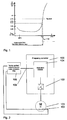
- Fig. 1 presents a typical characteristic curve of a PTC thermistor resistor, in which the resistance of the PTC thermistor resistor is presented as a function of temperature.
- the thermistor is selected according to the desired overtemperature limit.
- the overtemperature limit selected is T NAT + 15K, which corresponds to a resistance of ⁇ 4k ⁇ .
- T NAT characterizes the point of sharp change of the characteristic curve of the PTC resistor, which is utilized for the purpose of protection and according to which the PTC resistor is normally selected.
- thermistor resistor e.g. a Pt100 temperature sensor, or other temperature sensors.
- Fig. 2 presents a typical conventional solution controlled by a frequency converter and meeting the requirements of the ATEX directive, which sort is used to protect a motor situated in premises exposed to explosion hazard.
- a squirrel cage induction motor 101 provided with a PTC thermistor 102 is controlled by a frequency converter 100, in the power stage 103 of which are rectifying and inverting network bridges and load bridges as well as a control unit 104.
- the PTC thermistor disposed in the motor is connected to an external thermistor monitoring relay appliance 105, the activating output signal of which in an overtemperature situation is, for its part, connected to the stop inputs 106 of the frequency converter.
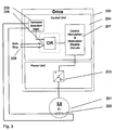
- Fig. 3 presents a solution according to this invention, in which is a squirrel cage induction motor 201, provided with e.g. a PTC thermistor 202, and the frequency converter 200 controlling it, in the power stage 203 of which are rectifying and inverting network bridges and load bridges provided with semiconductor switches (e.g. IGBT) as well as a control unit 204.
- the PTC thermistor 202 is connected directly to the frequency converter 200, and the detection logic 205 of the overtemperature limit of the thermistor is integrated directly into the frequency converter.
- the stop command given by the detection logic of the overtemperature situation of the thermistor is connected via the OR circuit 206 to the safety circuit 207 of the Safe Stop safety stop connection 208 or with similar, which implements the safe stop e.g. by preventing the controls of the IGBT switches of the power stage.
- Safe Stop stopping function 207 preventing unexpected start-up implements the requirements according to standards EN954-1, IEC 61508 or IEC 61800-5-2 and the monitoring input circuit 205 of the thermistor integrated into the frequency converter meets e.g. safety level 1 (SIL 1) set by the standard IEC 61508, a reliable thermistor input ensuring a reliable stopping function is formed as a combination of these.
- SIL 1 safety level 1
- a temperature thermistor which is needed in the scope of the ATEX directive to protect a motor situated in premises exposed to explosion hazard from overheating, can be connected directly to the frequency converter according to the invention. Thus an external thermistor relay is not needed.
- the safety circuit preventing the controls of the IGBT switches are incorporated in the control unit, which thus forms in its entirety a safety circuit for accidental start prevention with an integrated reliable thermistor input.
- the safety circuit can also be situated in the power stage.
Landscapes
- Engineering & Computer Science (AREA)
- Microelectronics & Electronic Packaging (AREA)
- Power Engineering (AREA)
- Inverter Devices (AREA)
- Control Of Ac Motors In General (AREA)
- Protection Of Generators And Motors (AREA)
Description
- For safety reasons the temperature of motors situated in premises exposed to explosion hazard may not in any circumstances increase to be too high. The normal method to prevent overheating is to locate one or more temperature sensors (thermistor) in the motor for measuring the temperature and to disconnect the power supply of the motor immediately when dangerous overheat is detected. Numerous official regulations address this issue, which belong to the field of technology defined by the so-called ATEX directive on potentially explosive atmospheres.
- The object of the present invention is an alternating-current electric motor drive which forms protection conforming to the standards, especially to the ATEX directive, in a situation of overheating of a motor.
- The conventional way of implementing overheating protection of a motor controlled by a frequency converter is to use an external thermistor relay, which is connected either to the stop input of the frequency converter or to an external contactor which disconnects the whole electricity supply of the motor drive.
-
US 4266257 discloses a motor overheating protection circuit with an enabling circuit which responds to a trigger signal provided by a reset circuit upon application of power to the protection circuit to enable a motor drive circuit to effect energization of the motor. A temperature sensing circuit provides a control signal indicative of the temperature of the motor, and should the control signal exceed the set point of a threshold detecting circuit of the enabling circuit, indicative of overheating of the motor, the enabling circuit inhibits the motor drive circuit deenergizing the motor.US 5158436 discloses a pump unit. The speed of the pump unit may be altered by changing the operating frequency of a frequency converter feeding the electric motor and which forms a structural unit with the pump unit. As soon as the pump unit has reached a parameter characterizing the thermal overload of the same, the frequency converter is controlled in a manner so as to reduce the speed, the reduced speed being greater or equal to half the normal speed.US 2002136642 A1 discloses a method for regulating a delivery variable of a pump. To avoid the influence of the temperature of the motor on the delivery variable at constant input power upon a change in the temperature in the motor a corresponding compensating variable is taken into account in the control for the purposes of correcting the input power. - According to the invention an input circuit connected to a thermistor located in the motor is integrated into a frequency converter, to which input circuit a safety circuit (a so-called Safe Stop circuit) that prevents unexpected starting or ensures safe stopping of the frequency converter is connected.
- By means of this invention the thermistor input can be incorporated directly into the frequency converter without a separate thermistor relay or other external control element of the thermistor, because when connected to the Safe Stop safety circuit the total solution stops an overheated motor safely.
- From the standpoint of safety and of complying with official regulations, the essential aspect of the solution according to the invention is the reliability of disconnection of the power supply, which is ensured because the Safe Stop safety circuit complies with the official regulations and standards regulating the function in question, such as e.g. EN954-1, IEC61508 and IEC61800-5-2.
- The characteristic features of the solution according to the invention are described in detail in the claims below.
- In the following, the invention will be described in more detail by the aid of an embodiment with reference to the attached drawing, wherein
-
Fig. 1 presents a typical characteristic curve of a PTC thermistor resistor. -
Fig. 2 presents a conventional solution for protecting a motor from overheat. -
Fig. 3 presents the solution for protecting a motor according to the invention integrated into a frequency converter. -
Fig. 1 presents a typical characteristic curve of a PTC thermistor resistor, in which the resistance of the PTC thermistor resistor is presented as a function of temperature. - The thermistor is selected according to the desired overtemperature limit. Generally the overtemperature limit selected is TNAT + 15K, which corresponds to a resistance of ≥ 4kΩ. TNAT characterizes the point of sharp change of the characteristic curve of the PTC resistor, which is utilized for the purpose of protection and according to which the PTC resistor is normally selected.
- Other than a PTC thermistor resistor can be used as a thermistor, e.g. a Pt100 temperature sensor, or other temperature sensors.
-
Fig. 2 presents a typical conventional solution controlled by a frequency converter and meeting the requirements of the ATEX directive, which sort is used to protect a motor situated in premises exposed to explosion hazard. In the solution a squirrelcage induction motor 101 provided with aPTC thermistor 102 is controlled by afrequency converter 100, in thepower stage 103 of which are rectifying and inverting network bridges and load bridges as well as acontrol unit 104. The PTC thermistor disposed in the motor is connected to an external thermistormonitoring relay appliance 105, the activating output signal of which in an overtemperature situation is, for its part, connected to thestop inputs 106 of the frequency converter. -
Fig. 3 presents a solution according to this invention, in which is a squirrelcage induction motor 201, provided with e.g. aPTC thermistor 202, and thefrequency converter 200 controlling it, in thepower stage 203 of which are rectifying and inverting network bridges and load bridges provided with semiconductor switches (e.g. IGBT) as well as acontrol unit 204. According to the principle of this invention thePTC thermistor 202 is connected directly to thefrequency converter 200, and thedetection logic 205 of the overtemperature limit of the thermistor is integrated directly into the frequency converter. The stop command given by the detection logic of the overtemperature situation of the thermistor is connected via theOR circuit 206 to thesafety circuit 207 of the Safe Stopsafety stop connection 208 or with similar, which implements the safe stop e.g. by preventing the controls of the IGBT switches of the power stage. - As the Safe
Stop stopping function 207 preventing unexpected start-up implements the requirements according to standards EN954-1, IEC 61508 or IEC 61800-5-2 and themonitoring input circuit 205 of the thermistor integrated into the frequency converter meets e.g. safety level 1 (SIL 1) set by the standard IEC 61508, a reliable thermistor input ensuring a reliable stopping function is formed as a combination of these. - A temperature thermistor, which is needed in the scope of the ATEX directive to protect a motor situated in premises exposed to explosion hazard from overheating, can be connected directly to the frequency converter according to the invention. Thus an external thermistor relay is not needed.
- In the example of
Fig. 3 the safety circuit preventing the controls of the IGBT switches are incorporated in the control unit, which thus forms in its entirety a safety circuit for accidental start prevention with an integrated reliable thermistor input. The safety circuit can also be situated in the power stage. - It is obvious to the person skilled in the art that the different embodiments of the invention are not limited solely to the example described above, but that they may be varied within the scope of the claims presented below. The arrangement can be on one or more circuit boards in the frequency converter, and it can be in the control part (control unit), in the power part (power stage), or in a combination of both.
Claims (4)
- An alternating current motor drive arrangement comprising a frequency converter (200) having a control unit (204) and a power unit (203), the control unit comprising a safety circuit connection (208),
the arrangement further comprising at least one thermistor (202) monitoring the temperature of an alternating-current electric motor (201) controlled by the frequency converter,
characterized in that the control unit further comprises a safety circuit (207) for preventing unexpected starting or ensuring safe stopping of the frequency converter and an input detection logic circuit (205),
wherein the input detection logic circuit (205) is connected to the thermistor (202) located in the motor (201), and
wherein the input detection logic circuit (205) and the safety circuit connection (208) are connected via an OR circuit (206) to the safety circuit (207). - The alternating current motor drive arrangement according to claim 1, characterized in that the safety circuit (207) is fitted to prevent the controls of the semiconductor switches of the frequency converter such that the input detection logic circuit (205) is connected to an accidental start prevention and/or stop safety circuit of the semiconductor switches of the frequency converter.
- The alternating current motor drive arrangement according to any of the preceding claims, characterized in that the safety circuit (207) is fitted to one or more circuit boards in the frequency converter.
- The alternating current motor drive arrangement according to any of the preceding claims, characterized in that the safety circuit (207) is fitted to the control unit (204) of the frequency converter, to the power stage, or to both.
Applications Claiming Priority (1)
| Application Number | Priority Date | Filing Date | Title |
|---|---|---|---|
| FI20060861A FI120477B (en) | 2006-09-27 | 2006-09-27 | Arrangements to protect an electric motor |
Publications (3)
| Publication Number | Publication Date |
|---|---|
| EP1906504A2 EP1906504A2 (en) | 2008-04-02 |
| EP1906504A3 EP1906504A3 (en) | 2011-11-16 |
| EP1906504B1 true EP1906504B1 (en) | 2016-03-23 |
Family
ID=37067184
Family Applications (1)
| Application Number | Title | Priority Date | Filing Date |
|---|---|---|---|
| EP07075785.1A Revoked EP1906504B1 (en) | 2006-09-27 | 2007-09-11 | Protection arrangement of an electric motor |
Country Status (3)
| Country | Link |
|---|---|
| US (1) | US7928679B2 (en) |
| EP (1) | EP1906504B1 (en) |
| FI (1) | FI120477B (en) |
Families Citing this family (6)
| Publication number | Priority date | Publication date | Assignee | Title |
|---|---|---|---|---|
| CN102420417B (en) * | 2011-12-21 | 2014-01-15 | 芜湖天宇科技开发有限公司 | A wire-wound motor protector and its protection method |
| CN102513377B (en) * | 2011-12-31 | 2015-01-28 | 太原重工股份有限公司 | Motor monitoring system of three-roller continuous tube-rolling mill |
| CN104852356B (en) * | 2014-02-17 | 2018-09-21 | 伊顿公司 | The control protective unit of motor |
| US9722415B2 (en) * | 2015-07-20 | 2017-08-01 | Dresser, Inc. | Regulating temperature on an actuator |
| DE102017127966A1 (en) * | 2017-11-27 | 2019-05-29 | Kriwan Industrie-Elektronik Gmbh | Motor protection device and method for monitoring an electric motor |
| FR3093251A1 (en) * | 2019-02-22 | 2020-08-28 | Moteurs Leroy-Somer | Variable speed drive usable in explosive atmospheres |
Citations (2)
| Publication number | Priority date | Publication date | Assignee | Title |
|---|---|---|---|---|
| DE10261454A1 (en) | 2002-12-31 | 2004-07-22 | Danfoss Drives A/S | Motor control with a secure hold |
| US20050123408A1 (en) | 2003-12-08 | 2005-06-09 | Koehl Robert M. | Pump control system and method |
Family Cites Families (13)
| Publication number | Priority date | Publication date | Assignee | Title |
|---|---|---|---|---|
| US4266257A (en) | 1978-10-02 | 1981-05-05 | Johnson Controls, Inc. | Motor over-heating protection circuit |
| US4954923A (en) * | 1988-08-19 | 1990-09-04 | Cooper Industries, Inc. | Intrinsic safety module interface |
| JPH0336985A (en) | 1989-06-30 | 1991-02-18 | Mitsubishi Electric Corp | Motor-driven blower |
| US5061884A (en) | 1990-02-12 | 1991-10-29 | Kb Electronics, Inc. | Current limiting control circuit for D.C. motors with line dropout protection |
| DE4010049C1 (en) | 1990-03-29 | 1991-10-10 | Grundfos International A/S, Bjerringbro, Dk | Pump unit for heating or cooling circuit - uses frequency regulator to reduce rotation of pump motor upon detected overheating |
| US5585025A (en) * | 1993-09-13 | 1996-12-17 | Softub, Inc. | SPA control circuit |
| JPH0787602A (en) * | 1993-09-17 | 1995-03-31 | Matsushita Electric Ind Co Ltd | Electric vehicle protection device |
| JPH08219058A (en) * | 1995-02-09 | 1996-08-27 | Matsushita Electric Ind Co Ltd | Hermetic electric compressor |
| US5841648A (en) * | 1997-05-29 | 1998-11-24 | Micro Motion, Inc. | Adjustable voltage converter utilizing a charge pump |
| JPH11239688A (en) | 1998-02-26 | 1999-09-07 | Matsushita Electric Ind Co Ltd | Washing machine |
| US6111738A (en) * | 1998-05-22 | 2000-08-29 | Diagnostic Instruments Ltd. | Intrinsically safe circuits |
| US6468042B2 (en) | 1999-07-12 | 2002-10-22 | Danfoss Drives A/S | Method for regulating a delivery variable of a pump |
| JP3994029B2 (en) | 2002-05-30 | 2007-10-17 | アスモ株式会社 | Motor control device and motor for air conditioner |
-
2006
- 2006-09-27 FI FI20060861A patent/FI120477B/en not_active IP Right Cessation
-
2007
- 2007-09-11 EP EP07075785.1A patent/EP1906504B1/en not_active Revoked
- 2007-09-19 US US11/902,156 patent/US7928679B2/en active Active
Patent Citations (2)
| Publication number | Priority date | Publication date | Assignee | Title |
|---|---|---|---|---|
| DE10261454A1 (en) | 2002-12-31 | 2004-07-22 | Danfoss Drives A/S | Motor control with a secure hold |
| US20050123408A1 (en) | 2003-12-08 | 2005-06-09 | Koehl Robert M. | Pump control system and method |
Non-Patent Citations (4)
| Title |
|---|
| "Reliable Drive solutions for the chemical industry", DANFOSS, April 2006 (2006-04-01), pages 1 - 12, XP055335358 |
| "VLT: Sichere Antriebslösungen für die chemische Industrie", DANFOSS, April 2006 (2006-04-01), pages 1 - 12, XP055335350 |
| ABB: "ATEX cetified thermal motor protection function ACS 800-07, ACS 800-U7, ACS 800 Multidrive", USER'S MANUAL ACS 800, 22 May 2006 (2006-05-22), XP055335340 |
| DOGAN IBRAHIM, ISBN: 0 7506 5556 9, article DOGAN IBRAHIM: "Microcontroller Based Temperature Monitoring and Control", pages: 107 - 109, XP055335768 |
Also Published As
| Publication number | Publication date |
|---|---|
| EP1906504A2 (en) | 2008-04-02 |
| US20080074069A1 (en) | 2008-03-27 |
| FI120477B (en) | 2009-10-30 |
| US7928679B2 (en) | 2011-04-19 |
| EP1906504A3 (en) | 2011-11-16 |
| FI20060861A0 (en) | 2006-09-27 |
| FI20060861L (en) | 2008-03-28 |
Similar Documents
| Publication | Publication Date | Title |
|---|---|---|
| US7928679B2 (en) | Protection arrangement of an electric motor | |
| US20140368956A1 (en) | Apparatus, System, and/or Method for Intelligent Motor Protection and/or Control | |
| US6297573B1 (en) | Three-phase motor | |
| US10756652B2 (en) | Motor protection and control apparatus, system, and/or method | |
| US8692416B2 (en) | Overload protection of a voltage reduction device | |
| CN107636920B (en) | Over temperature protection | |
| KR100918454B1 (en) | Heating line overheat protection circuit when power control element control of electric mat or electric hot water mat temperature controller is impossible | |
| CN209375118U (en) | Devices for detecting temperature rises and EC motors with shafts | |
| KR101386507B1 (en) | Protection apparatus for compressor and control method thereof | |
| US11581727B2 (en) | Assembly for monitoring a winding threshold temperature | |
| KR101491655B1 (en) | Motor Control Device Using Driving Current | |
| UA61537A (en) | Device for protecting a motor and equipment coupled with the motor | |
| US3249816A (en) | Overtemperature protected apparatus | |
| KR101364123B1 (en) | Apparatus for preventing overheating of cooking appliance | |
| RU2291538C2 (en) | Electric motor protective gear | |
| JP2005253195A (en) | Power supply | |
| SU1125697A1 (en) | Device for protecting electric motor against overheat | |
| KR20120107827A (en) | A circuit breaker in heating apparatus by short detection within heating line | |
| HK1154707B (en) | Overload protection of a voltage reduction device | |
| KR20180106312A (en) | Motor protection relay and control method thereof | |
| PL162258B1 (en) | Time delay protection system for the overload of the electric motor, especially of the mining machine | |
| KR20010000610U (en) | Aaaaa |
Legal Events
| Date | Code | Title | Description |
|---|---|---|---|
| PUAI | Public reference made under article 153(3) epc to a published international application that has entered the european phase |
Free format text: ORIGINAL CODE: 0009012 |
|
| AK | Designated contracting states |
Kind code of ref document: A2 Designated state(s): AT BE BG CH CY CZ DE DK EE ES FI FR GB GR HU IE IS IT LI LT LU LV MC MT NL PL PT RO SE SI SK TR |
|
| AX | Request for extension of the european patent |
Extension state: AL BA HR MK YU |
|
| PUAL | Search report despatched |
Free format text: ORIGINAL CODE: 0009013 |
|
| AK | Designated contracting states |
Kind code of ref document: A3 Designated state(s): AT BE BG CH CY CZ DE DK EE ES FI FR GB GR HU IE IS IT LI LT LU LV MC MT NL PL PT RO SE SI SK TR |
|
| AX | Request for extension of the european patent |
Extension state: AL BA HR MK RS |
|
| RIC1 | Information provided on ipc code assigned before grant |
Ipc: H02H 7/085 20060101AFI20111011BHEP |
|
| 17P | Request for examination filed |
Effective date: 20120510 |
|
| AKX | Designation fees paid |
Designated state(s): AT BE BG CH CY CZ DE DK EE ES FI FR GB GR HU IE IS IT LI LT LU LV MC MT NL PL PT RO SE SI SK TR |
|
| 17Q | First examination report despatched |
Effective date: 20130121 |
|
| REG | Reference to a national code |
Ref country code: DE Ref legal event code: R079 Ref document number: 602007045388 Country of ref document: DE Free format text: PREVIOUS MAIN CLASS: H02H0007085000 Ipc: H02H0009000000 |
|
| GRAP | Despatch of communication of intention to grant a patent |
Free format text: ORIGINAL CODE: EPIDOSNIGR1 |
|
| RIC1 | Information provided on ipc code assigned before grant |
Ipc: H02H 9/00 20060101AFI20151006BHEP Ipc: H02H 7/085 20060101ALI20151006BHEP |
|
| INTG | Intention to grant announced |
Effective date: 20151029 |
|
| RIN1 | Information on inventor provided before grant (corrected) |
Inventor name: MERILINNA, PAAVO Inventor name: CARLSSON, HANS Inventor name: RAJAKANGAS, KIMMO |
|
| RAP1 | Party data changed (applicant data changed or rights of an application transferred) |
Owner name: VACON OY |
|
| GRAS | Grant fee paid |
Free format text: ORIGINAL CODE: EPIDOSNIGR3 |
|
| GRAA | (expected) grant |
Free format text: ORIGINAL CODE: 0009210 |
|
| AK | Designated contracting states |
Kind code of ref document: B1 Designated state(s): AT BE BG CH CY CZ DE DK EE ES FI FR GB GR HU IE IS IT LI LT LU LV MC MT NL PL PT RO SE SI SK TR |
|
| REG | Reference to a national code |
Ref country code: GB Ref legal event code: FG4D |
|
| REG | Reference to a national code |
Ref country code: CH Ref legal event code: EP |
|
| REG | Reference to a national code |
Ref country code: AT Ref legal event code: REF Ref document number: 784000 Country of ref document: AT Kind code of ref document: T Effective date: 20160415 |
|
| REG | Reference to a national code |
Ref country code: IE Ref legal event code: FG4D |
|
| REG | Reference to a national code |
Ref country code: DE Ref legal event code: R096 Ref document number: 602007045388 Country of ref document: DE |
|
| REG | Reference to a national code |
Ref country code: LT Ref legal event code: MG4D |
|
| REG | Reference to a national code |
Ref country code: NL Ref legal event code: MP Effective date: 20160323 |
|
| PG25 | Lapsed in a contracting state [announced via postgrant information from national office to epo] |
Ref country code: GR Free format text: LAPSE BECAUSE OF FAILURE TO SUBMIT A TRANSLATION OF THE DESCRIPTION OR TO PAY THE FEE WITHIN THE PRESCRIBED TIME-LIMIT Effective date: 20160624 Ref country code: FI Free format text: LAPSE BECAUSE OF FAILURE TO SUBMIT A TRANSLATION OF THE DESCRIPTION OR TO PAY THE FEE WITHIN THE PRESCRIBED TIME-LIMIT Effective date: 20160323 |
|
| REG | Reference to a national code |
Ref country code: AT Ref legal event code: MK05 Ref document number: 784000 Country of ref document: AT Kind code of ref document: T Effective date: 20160323 |
|
| PG25 | Lapsed in a contracting state [announced via postgrant information from national office to epo] |
Ref country code: LV Free format text: LAPSE BECAUSE OF FAILURE TO SUBMIT A TRANSLATION OF THE DESCRIPTION OR TO PAY THE FEE WITHIN THE PRESCRIBED TIME-LIMIT Effective date: 20160323 Ref country code: LT Free format text: LAPSE BECAUSE OF FAILURE TO SUBMIT A TRANSLATION OF THE DESCRIPTION OR TO PAY THE FEE WITHIN THE PRESCRIBED TIME-LIMIT Effective date: 20160323 Ref country code: NL Free format text: LAPSE BECAUSE OF FAILURE TO SUBMIT A TRANSLATION OF THE DESCRIPTION OR TO PAY THE FEE WITHIN THE PRESCRIBED TIME-LIMIT Effective date: 20160323 Ref country code: SE Free format text: LAPSE BECAUSE OF FAILURE TO SUBMIT A TRANSLATION OF THE DESCRIPTION OR TO PAY THE FEE WITHIN THE PRESCRIBED TIME-LIMIT Effective date: 20160323 |
|
| PG25 | Lapsed in a contracting state [announced via postgrant information from national office to epo] |
Ref country code: EE Free format text: LAPSE BECAUSE OF FAILURE TO SUBMIT A TRANSLATION OF THE DESCRIPTION OR TO PAY THE FEE WITHIN THE PRESCRIBED TIME-LIMIT Effective date: 20160323 Ref country code: IS Free format text: LAPSE BECAUSE OF FAILURE TO SUBMIT A TRANSLATION OF THE DESCRIPTION OR TO PAY THE FEE WITHIN THE PRESCRIBED TIME-LIMIT Effective date: 20160723 Ref country code: PL Free format text: LAPSE BECAUSE OF FAILURE TO SUBMIT A TRANSLATION OF THE DESCRIPTION OR TO PAY THE FEE WITHIN THE PRESCRIBED TIME-LIMIT Effective date: 20160323 |
|
| PG25 | Lapsed in a contracting state [announced via postgrant information from national office to epo] |
Ref country code: SK Free format text: LAPSE BECAUSE OF FAILURE TO SUBMIT A TRANSLATION OF THE DESCRIPTION OR TO PAY THE FEE WITHIN THE PRESCRIBED TIME-LIMIT Effective date: 20160323 Ref country code: PT Free format text: LAPSE BECAUSE OF FAILURE TO SUBMIT A TRANSLATION OF THE DESCRIPTION OR TO PAY THE FEE WITHIN THE PRESCRIBED TIME-LIMIT Effective date: 20160725 Ref country code: ES Free format text: LAPSE BECAUSE OF FAILURE TO SUBMIT A TRANSLATION OF THE DESCRIPTION OR TO PAY THE FEE WITHIN THE PRESCRIBED TIME-LIMIT Effective date: 20160323 Ref country code: AT Free format text: LAPSE BECAUSE OF FAILURE TO SUBMIT A TRANSLATION OF THE DESCRIPTION OR TO PAY THE FEE WITHIN THE PRESCRIBED TIME-LIMIT Effective date: 20160323 Ref country code: RO Free format text: LAPSE BECAUSE OF FAILURE TO SUBMIT A TRANSLATION OF THE DESCRIPTION OR TO PAY THE FEE WITHIN THE PRESCRIBED TIME-LIMIT Effective date: 20160323 Ref country code: CZ Free format text: LAPSE BECAUSE OF FAILURE TO SUBMIT A TRANSLATION OF THE DESCRIPTION OR TO PAY THE FEE WITHIN THE PRESCRIBED TIME-LIMIT Effective date: 20160323 |
|
| REG | Reference to a national code |
Ref country code: DE Ref legal event code: R026 Ref document number: 602007045388 Country of ref document: DE |
|
| PLBI | Opposition filed |
Free format text: ORIGINAL CODE: 0009260 |
|
| PLBI | Opposition filed |
Free format text: ORIGINAL CODE: 0009260 |
|
| PG25 | Lapsed in a contracting state [announced via postgrant information from national office to epo] |
Ref country code: IT Free format text: LAPSE BECAUSE OF FAILURE TO SUBMIT A TRANSLATION OF THE DESCRIPTION OR TO PAY THE FEE WITHIN THE PRESCRIBED TIME-LIMIT Effective date: 20160323 Ref country code: BE Free format text: LAPSE BECAUSE OF FAILURE TO SUBMIT A TRANSLATION OF THE DESCRIPTION OR TO PAY THE FEE WITHIN THE PRESCRIBED TIME-LIMIT Effective date: 20160323 |
|
| 26 | Opposition filed |
Opponent name: SEW EURODRIVE GMBH & CO. Effective date: 20161212 |
|
| 26 | Opposition filed |
Opponent name: ABB OY Effective date: 20161222 |
|
| PLAX | Notice of opposition and request to file observation + time limit sent |
Free format text: ORIGINAL CODE: EPIDOSNOBS2 |
|
| PG25 | Lapsed in a contracting state [announced via postgrant information from national office to epo] |
Ref country code: DK Free format text: LAPSE BECAUSE OF FAILURE TO SUBMIT A TRANSLATION OF THE DESCRIPTION OR TO PAY THE FEE WITHIN THE PRESCRIBED TIME-LIMIT Effective date: 20160323 |
|
| PG25 | Lapsed in a contracting state [announced via postgrant information from national office to epo] |
Ref country code: BG Free format text: LAPSE BECAUSE OF FAILURE TO SUBMIT A TRANSLATION OF THE DESCRIPTION OR TO PAY THE FEE WITHIN THE PRESCRIBED TIME-LIMIT Effective date: 20160623 |
|
| PG25 | Lapsed in a contracting state [announced via postgrant information from national office to epo] |
Ref country code: MC Free format text: LAPSE BECAUSE OF FAILURE TO SUBMIT A TRANSLATION OF THE DESCRIPTION OR TO PAY THE FEE WITHIN THE PRESCRIBED TIME-LIMIT Effective date: 20160323 |
|
| REG | Reference to a national code |
Ref country code: CH Ref legal event code: PL |
|
| GBPC | Gb: european patent ceased through non-payment of renewal fee |
Effective date: 20160911 |
|
| PLBB | Reply of patent proprietor to notice(s) of opposition received |
Free format text: ORIGINAL CODE: EPIDOSNOBS3 |
|
| PG25 | Lapsed in a contracting state [announced via postgrant information from national office to epo] |
Ref country code: SI Free format text: LAPSE BECAUSE OF FAILURE TO SUBMIT A TRANSLATION OF THE DESCRIPTION OR TO PAY THE FEE WITHIN THE PRESCRIBED TIME-LIMIT Effective date: 20160323 |
|
| REG | Reference to a national code |
Ref country code: IE Ref legal event code: MM4A |
|
| REG | Reference to a national code |
Ref country code: FR Ref legal event code: ST Effective date: 20170531 |
|
| PG25 | Lapsed in a contracting state [announced via postgrant information from national office to epo] |
Ref country code: GB Free format text: LAPSE BECAUSE OF NON-PAYMENT OF DUE FEES Effective date: 20160911 Ref country code: CH Free format text: LAPSE BECAUSE OF NON-PAYMENT OF DUE FEES Effective date: 20160930 Ref country code: FR Free format text: LAPSE BECAUSE OF NON-PAYMENT OF DUE FEES Effective date: 20160930 Ref country code: IE Free format text: LAPSE BECAUSE OF NON-PAYMENT OF DUE FEES Effective date: 20160911 Ref country code: LI Free format text: LAPSE BECAUSE OF NON-PAYMENT OF DUE FEES Effective date: 20160930 |
|
| PG25 | Lapsed in a contracting state [announced via postgrant information from national office to epo] |
Ref country code: LU Free format text: LAPSE BECAUSE OF NON-PAYMENT OF DUE FEES Effective date: 20160911 |
|
| PLAB | Opposition data, opponent's data or that of the opponent's representative modified |
Free format text: ORIGINAL CODE: 0009299OPPO |
|
| R26 | Opposition filed (corrected) |
Opponent name: ABB OY Effective date: 20161222 |
|
| PG25 | Lapsed in a contracting state [announced via postgrant information from national office to epo] |
Ref country code: CY Free format text: LAPSE BECAUSE OF FAILURE TO SUBMIT A TRANSLATION OF THE DESCRIPTION OR TO PAY THE FEE WITHIN THE PRESCRIBED TIME-LIMIT Effective date: 20160323 Ref country code: HU Free format text: LAPSE BECAUSE OF FAILURE TO SUBMIT A TRANSLATION OF THE DESCRIPTION OR TO PAY THE FEE WITHIN THE PRESCRIBED TIME-LIMIT; INVALID AB INITIO Effective date: 20070911 |
|
| PG25 | Lapsed in a contracting state [announced via postgrant information from national office to epo] |
Ref country code: TR Free format text: LAPSE BECAUSE OF FAILURE TO SUBMIT A TRANSLATION OF THE DESCRIPTION OR TO PAY THE FEE WITHIN THE PRESCRIBED TIME-LIMIT Effective date: 20160323 Ref country code: MT Free format text: LAPSE BECAUSE OF NON-PAYMENT OF DUE FEES Effective date: 20160930 |
|
| REG | Reference to a national code |
Ref country code: DE Ref legal event code: R064 Ref document number: 602007045388 Country of ref document: DE Ref country code: DE Ref legal event code: R103 Ref document number: 602007045388 Country of ref document: DE |
|
| PGFP | Annual fee paid to national office [announced via postgrant information from national office to epo] |
Ref country code: DE Payment date: 20180828 Year of fee payment: 12 |
|
| RDAF | Communication despatched that patent is revoked |
Free format text: ORIGINAL CODE: EPIDOSNREV1 |
|
| RDAG | Patent revoked |
Free format text: ORIGINAL CODE: 0009271 |
|
| STAA | Information on the status of an ep patent application or granted ep patent |
Free format text: STATUS: PATENT REVOKED |
|
| 27W | Patent revoked |
Effective date: 20180925 |