EP1906276A2 - HMI-Ansichten von Modulen für industrielle Steuersysteme - Google Patents
HMI-Ansichten von Modulen für industrielle Steuersysteme Download PDFInfo
- Publication number
- EP1906276A2 EP1906276A2 EP07117192A EP07117192A EP1906276A2 EP 1906276 A2 EP1906276 A2 EP 1906276A2 EP 07117192 A EP07117192 A EP 07117192A EP 07117192 A EP07117192 A EP 07117192A EP 1906276 A2 EP1906276 A2 EP 1906276A2
- Authority
- EP
- European Patent Office
- Prior art keywords
- module
- hmi
- interface
- user
- modules
- Prior art date
- Legal status (The legal status is an assumption and is not a legal conclusion. Google has not performed a legal analysis and makes no representation as to the accuracy of the status listed.)
- Granted
Links
Images


Classifications
-
- G—PHYSICS
- G05—CONTROLLING; REGULATING
- G05B—CONTROL OR REGULATING SYSTEMS IN GENERAL; FUNCTIONAL ELEMENTS OF SUCH SYSTEMS; MONITORING OR TESTING ARRANGEMENTS FOR SUCH SYSTEMS OR ELEMENTS
- G05B19/00—Programme-control systems
- G05B19/02—Programme-control systems electric
- G05B19/18—Numerical control [NC], i.e. automatically operating machines, in particular machine tools, e.g. in a manufacturing environment, so as to execute positioning, movement or co-ordinated operations by means of programme data in numerical form
- G05B19/409—Numerical control [NC], i.e. automatically operating machines, in particular machine tools, e.g. in a manufacturing environment, so as to execute positioning, movement or co-ordinated operations by means of programme data in numerical form characterised by using manual input [MDI] or by using control panel, e.g. controlling functions with the panel; characterised by control panel details, by setting parameters
-
- G—PHYSICS
- G05—CONTROLLING; REGULATING
- G05B—CONTROL OR REGULATING SYSTEMS IN GENERAL; FUNCTIONAL ELEMENTS OF SUCH SYSTEMS; MONITORING OR TESTING ARRANGEMENTS FOR SUCH SYSTEMS OR ELEMENTS
- G05B19/00—Programme-control systems
- G05B19/02—Programme-control systems electric
- G05B19/04—Programme control other than numerical control, i.e. in sequence controllers or logic controllers
- G05B19/042—Programme control other than numerical control, i.e. in sequence controllers or logic controllers using digital processors
- G05B19/0426—Programming the control sequence
-
- G—PHYSICS
- G05—CONTROLLING; REGULATING
- G05B—CONTROL OR REGULATING SYSTEMS IN GENERAL; FUNCTIONAL ELEMENTS OF SUCH SYSTEMS; MONITORING OR TESTING ARRANGEMENTS FOR SUCH SYSTEMS OR ELEMENTS
- G05B2219/00—Program-control systems
- G05B2219/20—Pc systems
- G05B2219/23—Pc programming
- G05B2219/23258—GUI graphical user interface, icon, function bloc editor, labview
-
- G—PHYSICS
- G05—CONTROLLING; REGULATING
- G05B—CONTROL OR REGULATING SYSTEMS IN GENERAL; FUNCTIONAL ELEMENTS OF SUCH SYSTEMS; MONITORING OR TESTING ARRANGEMENTS FOR SUCH SYSTEMS OR ELEMENTS
- G05B2219/00—Program-control systems
- G05B2219/20—Pc systems
- G05B2219/23—Pc programming
- G05B2219/23261—Use control template library
-
- G—PHYSICS
- G05—CONTROLLING; REGULATING
- G05B—CONTROL OR REGULATING SYSTEMS IN GENERAL; FUNCTIONAL ELEMENTS OF SUCH SYSTEMS; MONITORING OR TESTING ARRANGEMENTS FOR SUCH SYSTEMS OR ELEMENTS
- G05B2219/00—Program-control systems
- G05B2219/30—Nc systems
- G05B2219/36—Nc in input of data, input key till input tape
- G05B2219/36133—MMI, HMI: man machine interface, communication
Definitions
- the subject invention relates generally to industrial control systems and more particularly to adaptable human machine interface functionality based on module types and users, where a module provides an abstract interface of logic and resources to perform an action.
- Industrial controllers historically have operated in factory networks where a plurality of controllers and associated I/O modules communicate. These lower level control elements are often in communication with higher level computing systems or servers that aggregate data from the controllers and help to manage day-to-day activities of an enterprise. As systems have become more complex however, communications and functional cooperation between components has become a challenge. For instance, when users purchase multiple products from one or more vendors there is often limited interoperability and consistency between such products. Software and control engineers must then learn their unique product and how the components interact with each other. Limited product and component consistency suggest that techniques engineers learn in one product do not necessarily carry over to other implementations. In general, control and application systems use different interfaces that make mapping difficult; meanwhile qualified personnel that understand both hardware and software environments are in short supply and command high salaries.
- system design does not sufficiently enable trade-offs between overhead burden (memory footprint, CPU cycles, and so forth) and application coupling.
- processing load should be better distributed across the system in accordance with system capabilities.
- a user initially designs and installs a control system suiting their immediate needs. Incremental changes are then applied to controllers and often new interface functions are added to the human machine interface (HMI) for such controllers.
- HMI human machine interface
- Current solutions however do not facilitate a smooth and uncomplicated transition for the respective changes.
- Multiple technologies underneath many vendors' products complicate configuration and management of systems. This is also aggravated when third party systems are involved. Such complexity hinders the system's capacity to provide higher-level information and reduces its ability to easily configure such systems.
- HMI Adaptable human machine interface
- the HMI components interact with a module that provides an association of logic with one or more resources, where the logic controls the state of the resources and the resources define components or states of a system that perform an action. Modules hide the user from internal interfaces, messages, and logic specific to the resources yet provide standard or generic interfaces to external systems.
- the HMI components are fluid and adapt to the module application to provide an experience that is more focused to the current task of the user and the state of the system.
- visual displays or interface inputs can change based upon the type of user or the desired operation that the user may be attempting.
- These include developer views that show all interfaces, logic, and data of the module; deployment views that show administrative elements of interest when configuring a system; runtime client and management views for debugging and maintenance of applications; and other resource/logic views for design and management of a control system or enterprise.
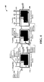
- Fig. 1 is a schematic block diagram illustrating a human machine interface (HMI) and logical modules for an industrial automation system.
- HMI human machine interface
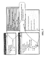
- Fig. 2 is a diagram illustrating module attributes.
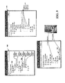
- Fig. 3 is a diagram illustrating an HMI developer view of modules.
- Fig. 4 is a diagram illustrating an HMI deployment manager view of modules.
- Fig. 5 is a diagram illustrating an HMI client view of modules.
- Figs. 6-11 illustrate example human machine interfaces and concepts.
- Fig. 12 is a flow diagram illustrating a module interface process.
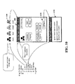
- Figs. 13-16 illustrate a common data model that can be employed with modules in an industrial automation system.
- a human machine interface (HMI) interface for an industrial automation system is provided.
- a module is provided that employs resources and logic to expose functionality of the module while providing generic interfaces to external components of the module.
- a human machine interface (HMI) component associated with the module adapts functionality of a display based at least in part on a type of user or application.
- the HMI component adapts functionality of one or more interface inputs based in part on the type of user or application.
- HMI components or modules can aggregate other HMI components or modules.
- HMI modules can filter and rearrange views of published interfaces based on user or program roll and location. For example, an HMI developer can be provided with a different set of functionality than a control engineer.
- a component may be, but is not limited to being, a process running on a processor, a processor, an object, an executable, a thread of execution, a program and a computer.
- an application running on a server and the server can be components.
- One or more components may reside within a process and/or thread of execution and a component may be localized on one computer and/or distributed between two or more computers, industrial controllers, and/or modules communicating therewith.
- a system 100 illustrates a module component 110 (hereinafter referred to as a module) and interface for an industrial automation system.
- the module 110 is employed to define, interface, and execute functionality of one or more industrial control system components 120 which are described in more detail below.
- the modules 110 can be accessed across a network 114 from the control components 120.
- the network 114 also allows online access to the modules 110 and their respective control components 120 and also enables creating the modules 110 in an offline manner such as in a computer database (not shown). When created offline, the modules 110 can subsequently be downloaded for execution on the control components 120.
- Modules 110 can be interfaced by users via a human machine interface (HMI) component 124 (described below) and/or can be configured to interact with a plurality of other modules 110 or control components 120.
- HMI human machine interface
- the module 110 is an association of logic 130 with one or more resources 140.
- the logic 130 includes program code that can alter the state of a resource 140 for example, ladder code, function chart, script, JAVA, C code, and so forth.
- the resources 140 are those components or elements that perform an activity in a system including equipment and personnel that perform work in a system. Other examples of types of resources 140 include Equipment, Material, Personnel, Segments and Storage. Personnel and equipment (machines) can perform activities in a system. Resources that can perform work can be classified as active resources (e . g ., CNC machine, Injection molding machine), whereas other equipment resources can be considered passive resources ( e . g ., sensor, material).
- Module classes and templates can be maintained in libraries which facilitate access to desired system functionality and further promote system integration.
- Resources 140 can have various states associated therewith such as common S88 state classifications including idle, hold, abort, run, reset, stop, restart, and so forth where the module 110 can present logic 130 to represent state machines that manage the state of the resource 140.
- An instance of the module 110 can be considered a real item in the automation system 100, typically viewed in an Organizational View, Geographical View, or Asset Management View, for example.
- the HMI component 124 is adaptable to provide a desired view of the module 110 depending on the type of user or application involved as determined by an application component 150.
- the application component 150 determines the type of role for the user or determines a particular application that the user has selected and alters a display or "view" presented to the user, where the display provides one or more display objects 160 associated with an application.
- Adaptability includes adapting available inputs 170 or selection options available for the HMI component 124 depending on the role or type of user and/or application.
- the role of the user may be determined from a database and when the user logs in, the role is determined from a table in the database.
- the user may have different roles including design, administrative, maintenance, and so forth which can be determined by direct input from the user or inferred from the task at hand (e.g., application input selection defining role, intelligent components such as classifiers monitoring the application to determine role).
- the HMI component 124 adapts to the module 110 to provide an experience that is more focused to the current task of the user and the state of the system 100.
- display objects 160 or interface inputs 170 can change based upon the type of user or the desired operation that the user may be attempting.
- These include developer views that show substantially all interfaces, logic, and data of the module; deployment views that show administrative elements of interest when configuring a system; runtime client and management views for debugging and maintenance of applications; and other resource/logic views for design and management of a control system or enterprise 100.
- various interfaces 124 can be provided to manipulate the modules 110 and organizational data models described below where various examples are illustrated in more detail below.
- This can include a Graphical User Interface (GUI) to interact with the module 110 or other components of the hierarchy such as any type of application that sends, retrieves, processes, and/or manipulates factory or enterprise data, receives, displays, formats, and/or communicates data, and/or facilitates operation of the system 100.
- GUI Graphical User Interface
- interfaces 124 can also be associated with an engine, server, client, editor tool or web browser although other type applications can be utilized.
- the GUI can include a display having one or more display objects 160 for manipulating the module 110 including such aspects as configurable icons, buttons, sliders, input boxes, selection options, menus, tabs and so forth having multiple configurable dimensions, shapes, colors, text, data and sounds to facilitate operations with the model.
- the GUI can also include a plurality of other inputs 170 or controls for adjusting and configuring one or more aspects. This can include receiving user commands from a mouse, keyboard, speech input, web site, remote web service or other device such as a camera or video input to affect or modify operations of the GUI.
- the components 120 can include various computer or network components such as servers, clients, programmable logic controllers (PLCs), communications modules, mobile computers, wireless components, control components and so forth which are capable of interacting across the network 114.
- PLC programmable logic controllers
- the term PLC as used herein can include functionality that can be shared across multiple components, systems, and or networks 114.
- one or more PLCs can communicate and cooperate with various network devices across the network 114. This can include substantially any type of control, communications module, computer, I/O device, sensor, Human Machine Interface (HMI)) that communicate via the network 114 which includes control, automation, and/or public networks.
- the PLC can also communicate to and control various other devices such as Input/Output modules including Analog, Digital, Programmed/Intelligent I/O modules, other programmable controllers, communications modules, sensors, output devices, and the like.
- the network 114 can include public networks such as the Internet, Intranets, and automation networks such as Control and Information Protocol (CIP) networks including DeviceNet and ControlNet. Other networks include Ethernet, DH/DH+, Remote I/O, Fieldbus, Modbus, Profibus, wireless networks, serial protocols, and so forth.
- the network devices can include various possibilities (hardware and/or software components). These include components such as switches with virtual local area network (VLAN) capability, LANs, WANs, proxies, gateways, routers, firewalls, virtual private network (VPN) devices, servers, clients, computers, configuration tools, monitoring tools, and/or other devices.
- VLAN virtual local area network
- WANs wide area network
- proxies gateways
- routers virtual private network
- VPN virtual private network
- module attributes 200 are illustrated.
- the attributes 200 depicted in Fig. 2 include a common (or exemplary) representation that can be modules from modules. Generally, a set of standard attributes can be determined that are common to all modules. Similarly, for other types of modules described below, additional standard attributes can be defined.
- An example of a property 210 available on modules includes attributes such as Fault and Status at 214. Active resource modules can support additional properties 210 such as available/ unavailable.
- Attributes presented below are represented associations from the module to objects which may be internal in a common data model (See. Figs. 8-11) or elsewhere (e.g., CAD Files).
- standard public interfaces can be provided. These interfaces 220 publish verbs 224 that are available to external systems and are documented activities that hide the complexity of the underlying code used to implement the interface. Interfaces 220 can be considered into at least two common usage scenarios. For example, interfaces 220 can be used as access points that can be used to hook in real time diagnostics, security and so forth.
- Public verbs 224 initiate an action within the module.
- the activity is described to clients of the interface 220.
- the implementation is considered private and is not presented to clients - for example, Open, Stop, Abort, Shut, and so forth.
- a data value property 210 provides public access to information that is used by the module during its operation and can be provided by request values and/or internal values (or an equivalent).
- the association of logic to transfer request values to internal values and vice versa are referred to as get and set logic for the value. It is noted that in a controller, if there is not a set routine to transfer request values to internal values, the internal value can overwrite the request value on the next scan providing read only capability.
- the properties 210 can be considered in at least two classifications. States have special significance for production systems and can have a specific set of values that can be represented by range or enumeration.
- a state can represent the current status of the primary resource being encapsulated by the module e.g., Percent open, Mode, Service (in, out), and so forth.
- Information that is used by the module during its operation includes access to data that is provided by interfaces 220. e.g., Conversion Map, Name, Description, expiry date, personnel contact information.
- Some properties 210 can be common to all instances of resource modules (e.g., scanned copy of resource specification documents), whereas other properties 210 are specific to each module instance (e.g., Status, percent open).
- internal resource interfaces include interfaces from logic 240 in the module to the resource being managed at 250, where the logic includes code and/or configuration that processes a command and/or updates state and data properties. In some cases, this can be hardware such as I/O interfaces, or in other cases it is to subordinate resource control modules that have direct interfaces. Some examples include I/O mapping, material management logic routines, and so forth.
- These interfaces 230 are internal to the module enabling the modules public interfaces 220 and properties 210 to be the boundary to other system components. Modules that wrap different resources but support the same public properties/interfaces can be exchanged without disrupting interfaces to other components. Generally, I/O mapping and system messaging interfaces are exposed during deployment bind processes. When bound, external interfaces 220 to runtime systems may then consider these interfaces as internal.
- alarm and event messages can be provided which include messages that exposed as runtime messages visible to external systems during the execution of the module. This includes alarms and events explicitly coded by the developer and system messages promoted to be visible by external systems.
- one or more artifacts include information that document the operation and structure of the resource such as for example, wiring diagrams, warranties, payroll, parts supplier information, and so forth.
- Visualization aspects include associated graphics that present the resource state and properties to applications interacting with the resource. For example: faceplates, icons, state overlays, edit dialogs, help files.
- system messages allow modules to listen for and publish data model messages to external components. Inbound messages are typically used to manage modules (configure, initialize, propagate properties, and so forth) and publish messages on module activity (resource state, data model messages, and so forth).
- FIG. 3 an example HMI developer view of modules 300 is illustrated.
- an internal "Module Developers" view of three interconnected modules is illustrated at 300.
- more or less than three modules can be shown in a given view depending upon the application.
- the developer of the module can see the inner workings of the module, associated code, and data used to provide the modules behavior.
- resource I/O and logic are modular and can be used to switch between resources internally without changing code.
- Valves can be changed without changing associated valve control logic at 310,320 thus avoiding revalidation requirements for the logic.
- Developer views can show all the various attributes described above with respect to Fig. 2 such as properties, interfaces, commands, verbs, messages, and so forth.
- Fig. 4 illustrates an example HMI deployment manager view of modules 400.
- the modules internal interfaces are bound to system messaging and I/O interfaces.
- an administrator can resolve the interface connections required for proper operation of the module both internally and externally.
- the logic component of the module and possibly some configuration data would be locked down to ensure the module retains its validated configuration.
- the process of deployment is then validated and associated with the template and/or instance created from the template (note: templates may not always be used in development).
- the view of the module presented in a deployment scenario is presented at 400.
- attributes associated with the module are bound to system components. For example, HMI screens are bound to view servers, the module is bound to (downloaded to) the controller, and device I/O on modules are matched to resource I/O in the control module. In some cases, other systems will detect the presence of the extra capability.
- logic and resources are hidden from view at 410-430 since these aspects are configured during development, yet the respective module interfaces (inputs and outputs of the modules) for deployment are exposed for use by the administrator. In this manner, the administrator can find and subsequently couple the relevant components of modules to configure a particular application from the modules.
- the module is not immediately made available to production, yet is available to production when the deployment lifecycle releases the module to production systems.
- external systems can incorporate the module or modules into their respective systems.
- Fig. 5 illustrates an example runtime client view of modules 500.
- An external "Runtime Clients" view is illustrated at 500.
- a runtime client sees a black box representation of the module.
- This representation includes: Public interfaces with clearly defined semantics; Public properties that can be used to configure the module and report the modules state; and Alarm and event messages that are published by the module.
- the internal workings of the modules are not shown where merely the function of the module is displayed such as in these examples, solenoid valve control 510, big valve control 520, and move material control 530.
- a plurality of different views and exposed interfaces are available depending on the type of user or application. These include administrators, developers, designers, maintenance engineers, users, managers, and so forth. For instance, system diagnostics and management applications interact with attributes associated with the module used in conjunction with various scenarios.
- the state of the module may be presented in production execution views whereas maintenance views may present CAD drawings, I/O wiring diagrams and message logs associated with the module, for example.
- associations of a set of information presented is determined by the product/application presenting the information that in turn can be relative to the determined user and their relationship to the particular application.
- a module can be presented in a number of different perspectives. Examples of these perspectives are equipment view versus process logic view of control modules and material versus material handling logic for material control modules. The choice of view can be dependant on the user configuring or managing the process. A process engineer who is concerned with managing control logic across a plant or enterprise may use a control module focused console whereas a maintenance engineer may prefer an equipment view of the same system.
- control module centric view the process engineer can navigate from control module templates, to the instances in an organizational model, and then on to the deployed instances in programmable controllers. They could similarly navigate in the opposite directions, for example locating the control module template from the deployed instance or an instance in the organizational model. Throughout these navigations, a consistent view is provided on the control logic of the modules.
- the maintenance engineer can navigate the same control system via a physical (geographical) view or perhaps through an asset management view.
- the maintenance engineer is not concerned with the control logic, but perhaps is interested in using an HMI terminal to examine the current state of a piece of equipment.
- one may not "see” or be exposed to any control logic, but rather have the ability to launch faceplates or view the various properties and artifacts of the equipment.
- Figs. 6-11 illustrate various aspects for HMI presentations.
- the data described herein can be broader than tag oriented or scalar data values. While interfaces based on tag data are employed in applications that deal with controllers and OPC data, higher level systems often require more complex message based interactions. Since common data model modules can be developed across a wide spectrum of plant applications, additional options are provided in the respective interface. Thus, the user can choose to define the module interface based on one or more of the following examples:
- Data - a data based interface is the traditional mechanism to access a module in a controller via tags and/or OLE for Process Control (OPC). Many users develop modules for equipment control using this method.
- Data based interfaces include attributes such as input or output and externally visible or not visible. These attributes are interpreted by the messaging services to facilitate the interaction of modules.
- Messages - a message based interface is commonly used in software modules to facilitate interactions at a higher level.
- the definition includes the messages sent and received as well as the payloads of each message.
- a message includes more complex data that is delivered as one unit.
- a method is a special case of a message that implies a request / response paradigm in the method exchange.
- a method may have input and output parameters (again hints to the messaging service) so that some data is sent to the receiving module while other data is returned from it.
- An event is another special case of a message that implies data broadcast from a module typically with little or no knowledge of who is receiving it. The definition of a broadcast event gives hints to the messaging services on how to deliver the message.
- Fig. 6 illustrates an example data based interface 600.
- Module interfaces that are based on data can look similar to the user-defined types that engineers use to interact with modules.
- Commands, status values, alarms, and events of the module are defined in terms of scalar data values such as Booleans (bits), integers, reals, and strings as illustrated at 610.
- the module logic at 610 then is designed to analyze these data values and perform algorithms or actions based on them,
- Fig. 7 illustrates an example message based interface 700
- Module interfaces based on messages are similar to interface definitions in object oriented programming.
- the designer defines a set of messages to send to the module (methods) and the messages sent by the module (events).
- Respective messages can include a set of parameters which are designated as inputs or outputs of the message.
- the module logic then is designed to respond to and send these messages in combination with the execution of its algorithms.
- An example, message based interface 700 is shown where attributes such as [in] at 710 or [out] at 720 imply message service functionality, whereas logic at 730 shows communications via such messages.
- Fig. 8 illustrates example categories 800 that may be employed with human machine interfaces described herein.
- the common data model (described below with respect to Figs. 14-17) provides a flexible framework for the definition of the interface for modules, and also a default set of categories for data.
- These categories 800 can provide mechanisms to configure what applications can access the data and how they interact with it.
- the data can be an input (write) to the module or an output (read-only) from it.
- the data be accessed from an operator display, programmatically or both situations.
- Default access and interaction policies for each category 800 are provided, but the user can also configure them to adjust the system to meet specific needs.
- commands are sent by the operator to a module from an HMI, MES application, or programmatic software to query the object to do something. These are inputs to the module to request that it performs some action. These could take the form of scalar data values that are written, as methods (with parameters) that are invoked, or as messages (with payload) that are sent. Some users may also want to partition commands into operator versus programmatic commands. This is supported through the addition of separate categories 800.
- status data represents the actual state or states (generically) of the control module class. Access to read status data is generally available to all applications. Status data can be configured to include target values, which represents the desired state of the object. This enables the user to track the target versus the actual state.
- categories 800 can include alarms that represent occurrences of an abnormal process, device or system event that typically require operator attention.
- Alarms include tracking of whether the alarm has been acknowledged or not. Alarms typically clear when the process has returned to normal and the operator has acknowledged the alarm. Additionally, mechanisms to suppress alarms, perhaps during certain process conditions or maintenance activities, are included as part of this category.
- events represent occurrences of normal processing that do not typically require operator attention. These might be diagnostic, tracking, material consumption, or audit trail events signaled by the module.
- configuration data is used to set up various features of a module, set ranges to match the process, or provide other static configuration data.
- Engineering units, raw units, other conversion factors, tuning constants, and other similar items can be provided as configuration data. These are typically accessed from the programming software or from advanced faceplates on the HMI (by authorized personnel).
- externals define the links to I/O modules and the field I/O points for the module. This may also include external connections to I/O module health status values, references to other objects, or other external data that the module requires.
- the externals are typically configured or programmed in the controller, and may not be accessible from an HMI, programmatic control, or MES application.
- interlocks are conditions that determine if the control should be disabled or enabled.
- Interlocks can also be external conditions that are met for the module to perform an action. Interlocks may or may not include bypasses to allow the operator to manipulate the module even when interlocks exist.
- Fig. 9 illustrates example interface scenarios.
- the definition of a module's interface in terms of the categories of data generally applies to all of the module objects. That is, predefined interfaces are defined in terms of the commands, status, alarms, events, and so forth that are supported. Similarly, the definition of an interface for a module class uses those same mechanisms; and the pattern continues on for module templates and instances.
- the designer chose to support the equipment control predefined interface for both of these classes, and also added the storage predefined interface to the tank at 920. Since both of these module classes support the equipment control interface, the resulting module template also supports that interface. Since the predefined interfaces only specify behavior, there is no logic to reconcile, and thus, the resulting interface of the module template is analogous to a union of the interfaces from the module classes that it implements. The interface 930 shows how this may appear to the user.
- the opportunity to generate the module document from its interfaces is provided as shown at 940.
- This may take the form of a simple printed report, but with evolution of document technologies to standard and open formats, a higher value proposition is to generate a reusable document that can then be associated with the module itself.
- editor or word application documents using XML formats provided by commercial software vendors can be employed. Since artifacts can be associated with common data model objects, these interface specifications can be generated for a module class, template, or instance.
- Fig. 10 illustrates example HMI faceplates.
- HMI faceplates provide a mechanism for uniform interaction from the operators of the control system.
- the engineer user has configured categories of data (e . g ., commands, status, alarms, events) and set the visibility and accessibility rules for that data.
- the data available for developing the HMI faceplates can thus be constrained by the definition of the interfaces.
- the authoring of the HMI faceplates for a module class or template involves creating a set of graphic displays, hooking them to the data defined in the module's interface, and defining the navigation between these displays.
- various HMI faceplate graphics can be employed.
- an icon faceplate was used on a higher level display, then the operator can navigate to the overview faceplate 1000 from the icon.
- the operator can use the Configure... button at 1010 on the overview faceplate 1000 to access a configuration faceplate 1020. Since during the authoring of the faceplate 1000, the data in the screen is bound to the interface of the module, the same HMI faceplate can be used for every instance of the module.
- the HMI faceplate 1000 is based on the interface definition of the module, changes to the interface (e . g ., the name of a status value) are reflected in the HMI code. That is, the user does not have to manually update the HMI faceplate; the system does it automatically. As shown, various icons can be provided at 1030.
- Fig. 11 illustrates aspects for generating default faceplates.
- the common data model system can provide additional value by generating default HMI faceplates based on the interface definitions of the module as illustrated at 1100. Since the system is aware of the definition of the various categories of data in the module interfaces, it can generate appropriate faceplates. That is, commands to the module can require buttons (or other actuators), status values are to be displayed, alarms are to be displayed and usually require an acknowledge button, configuration values should be read and written, and so forth. Thus, the system can automatically generate these default faceplates which the HMI author uses directly or more likely as a starting point for creating other customized screens.
- Fig. 12 illustrates a module interface process 1200 for an industrial automation system. While, for purposes of simplicity of explanation, the methodology is shown and described as a series of acts, it is to be understood and appreciated that the methodology is not limited by the order of acts, as some acts may occur in different orders and/or concurrently with other acts from that shown and described herein. For example, those skilled in the art will understand and appreciate that a methodology could alternatively be represented as a series of interrelated states or events, such as in a state diagram. Moreover, not all illustrated acts may be required to implement a methodology as described herein.
- module logic is defined. This includes the code (or hardware) that controls the actions defined in 1210. Such code can be of a higher level including structured programming languages and is generally contained within the module and hidden from view. As noted above, it is desired to expose functionality of a module in a generic manner while mitigating details of the inner workings of the module including the respective logic. Depending on the type of user however, module details may be exposed ( e . g ., Designer).
- one or more standard or generic interfaces are defined for the module. This includes defining high level abstractions for the interfaces rather than specific interfaces directed to a particular product.
- a type for a user or application is determined. For example, if a user is accessing a design menu for a module, then an interface may be displayed that shows intimate details of the module. If a manager were to view operations of a plant, higher level details such as a module's functions may be exposed or highlighted while hiding more esoteric details such as module code logic.
- user types can be defined for a plurality of different types of users or applications where such determinations can be inferred or queried from a profile of the user, for example.
- an interface is adapted and generated for the type of user or application determined at 1240. As there can be a plurality of different types of users or applications, a plurality of interfaces can be generated, where the respective interface shows or hides depending on the type of user or application determined at 1240.
- FIGs. 13-16 illustrate aspects of a common data model noted above.
- FIG. 13 hierarchical representations that can be employed in connection with a schema employed by programmable logic controllers to facilitate use of a hierarchically structured data model are illustrated.
- the hierarchies illustrated in this figure relate to equipment hierarchies, which can be integrated with procedure hierarchies to generate a robust representation of a plant (which is incorporated within a schema for use in connection with industrial controllers).
- a first hierarchy 1300 illustrates a representation of equipment within a plant given disparate processes.
- a hierarchy in accordance with a batch process can include a representation of an enterprise, site, area, process cell, unit, equipment module, and control module.
- a hierarchical representation of equipment within a continuous process can include representations of an enterprise, site, area, production unit, continuous unit, equipment module, and control module.
- an enterprise can represent an entirety of a company
- a site can represent a particular plant
- an area can represent a portion of the plant
- a process cell can include equipment utilized to complete a process
- a unit can relate to a unit of machinery within the process cell
- an equipment module can include a logical representation of portions of the process cell
- the control module can include basic elements, such as motors, valves, and the like.
- equipment modules can include equipment modules and control modules can include control modules.
- a second hierarchy 1302 can be utilized that represents each of the aforementioned hierarchical representations.
- the hierarchy 1302 can include representations of an enterprise, a site, an area, a work center, a work unit, an equipment module, and a control module.
- a common representation can be generated that adequately represents the hierarchy 1300.
- data objects can be associated with metadata indicating which type of process they are associated with. Therefore, data objects can be provided to an operator in a form that is consistent with normal usage within such process. For example, batch operators can utilize different terminology than a continuous process operator (as shown by the hierarchy 1300).
- Metadata can be employed to enable display of such data in accordance with known, conventional usage of such data.
- implementation of a schema in accordance with the hierarchy 1302 will be seamless to operators.
- only a portion of such representation can be utilized in a schema that is utilized by a controller. For instance, it may be desirable to house equipment modules and control modules within a controller. In another example, it may be desirable to include data objects representative of work centers and work units within a controller (but not equipment modules or control modules). The claimed subject matter is intended to encompass all such deviations of utilizing the hierarchy 1302 (or similar hierarchy) within a controller.
- a hierarchy 1400 represents procedures that can exist within a batch process.
- a procedure can relate to a high-level procedure, such as creation of a pharmaceutical drug.
- a unit procedure can be more specific, such as adding particular chemicals to a mix by way of a particular unit.
- a unit operation can be still more specific, and a phase can be yet more specific (relating to operation of low-level machines).
- a phase can relate to various states which can exist with respect to low-level equipment, such as stopping, starting, pausing a motor, opening and closing a valve, and the like.
- a hierarchy 1402 relating to a representation of equipment in, for example, a batch process is displayed adjacent to the hierarchy 1400.
- a hierarchy 1500 that represents one possible integration of the example hierarchies 1400 and 1402 (Fig. 14).
- a unit (such as a work unit described in Fig. 13) can be associated with an equipment procedure, an equipment unit procedure, an equipment operation, and an equipment phase).
- the procedures, operation, and phase can be associated with a particular work unit.
- An equipment module can be associated with one or more equipment phases, and can be above a control module in the hierarchy.
- a hierarchy 1600 that can be utilized in connection with equipment control is illustrated. The hierarchy is substantially similar to that described within the unit portion of the equipment unit. As stated above, the hierarchies illustrated in Figs.
- FIG. 13-16 can be based upon a standard, such as ISA 88,1SA 95, or other standard. Any suitable representation that can be utilized to model an entirety of a plant, however, is contemplated. Further, the representations shown in these figures can be directly implemented into a controller. For instance, data objects in accordance with any portion of the hierarchies described in Figs. 13-16 can be existent within a controller, together with state machines that enable creation of such objects.
- modules can be processed on various types of computing devices and resources, where some of these devices may be associated with an industrial control component and other devices associated with standalone or networked computing devices.
- computers can be provided to execute the above modules or associated data that include a processing unit, a system memory, and a system bus, for example.
- the system bus couples system components including, but not limited to, the system memory to the processing unit that can be any of various available processors. Dual microprocessors and other multiprocessor architectures also can be employed as the processing unit.
- the system bus can be any of several types of bus structure(s) including the memory bus or memory controller, a peripheral bus or external bus, and/or a local bus using any variety of available bus architectures including, but not limited to, 11-bit bus, Industrial Standard Architecture (ISA), Micro-Channel Architecture (MSA), Extended ISA (EISA), Intelligent Drive Electronics (IDE), VESA Local Bus (VLB), Peripheral Component Interconnect (PCI), Universal Serial Bus (USB), Advanced Graphics Port (AGP), Personal Computer Memory Card International Association bus (PCMCIA), and Small Computer Systems Interface (SCSI).
- ISA Industrial Standard Architecture
- MSA Micro-Channel Architecture
- EISA Extended ISA
- IDE Intelligent Drive Electronics
- VLB VESA Local Bus
- PCI Peripheral Component Interconnect
- USB Universal Serial Bus
- AGP Advanced Graphics Port
- PCMCIA Personal Computer Memory Card International Association bus
- SCSI Small Computer Systems Interface
- the system memory includes volatile memory and nonvolatile memory.
- the basic input/output system (BIOS) containing the basic routines to transfer information between elements within the computer, such as during start-up, is stored in nonvolatile memory.
- nonvolatile memory can include read only memory (ROM), programmable ROM (PROM), electrically programmable ROM (EPROM), electrically erasable ROM (EEPROM), or flash memory.
- Volatile memory includes random access memory (RAM), which acts as external cache memory.
- RAM is available in many forms such as synchronous RAM (SRAM), dynamic RAM (DRAM), synchronous DRAM (SDRAM), double data rate SDRAM (DDR SDRAM), enhanced SDRAM (ESDRAM), Synchlink DRAM (SLDRAM), and direct Rambus RAM (DRRAM).
- SRAM synchronous RAM
- DRAM dynamic RAM
- SDRAM synchronous DRAM
- DDR SDRAM double data rate SDRAM
- ESDRAM enhanced SDRAM
- SLDRAM Synchlink DRAM
- DRRAM direct Rambus RAM
- Computing devices also includes removable/non-removable, volatile/non-volatile computer storage media.
- software components can be provided that act as an intermediary between users and the basic computer resources described in suitable operating environment.
- Such software includes an operating system which can be stored on disk storage, acts to control and allocate resources of the computer system.
- System applications take advantage of the management of resources by operating system through program modules and program data stored either in system memory or on disk storage. It is to be appreciated that the present invention can be implemented with various operating systems or combinations of operating systems or shared with control systems.
- Computers can operate in a networked environment using logical connections to one or more remote computers, such as remote computer(s).
- the remote computer(s) can be a personal computer, a server, a router, a network PC, a workstation, a microprocessor based appliance, a peer device or other common network node and the like, and typically includes many or all of the elements described relative to computer, Remote computers can be logically connected through a network interface and then physically connected via communication connection.
- Network interfaces encompass communication networks such as local-area networks (LAN) and wide-area networks (WAN).
- LAN technologies include Fiber Distributed Data Interface (FDDI), Copper Distributed Data Interface (CDDI), Ethernet/IEEE 1102.3, Token Ring/IEEE 1102.5 and the like.
- WAN technologies include, but are not limited to, point-to-point links, circuit switching networks like Integrated Services Digital Networks (ISDN) and variations thereon, packet switching networks, and Digital Subscriber Lines (DSL), and wireless networks.
- ISDN Integrated Services
- the systems described above employing the authentication protocols can include one or more client(s).
- the client(s) can be hardware and/or software (e.g., threads, processes, computing/control devices).
- the systems can also include one or more server(s).
- the server(s) can also be hardware and/or software (e.g., threads, processes, computing/control devices).
- the servers can house threads to perform transformations by employing the authentication protocol, for example.
- One possible communication between a client and a server may be in the form of a data packet adapted to be transmitted between two or more computer processes.
- HMI human machine interface
- a module employs resources and logic to expose functionality of the module while providing generic interfaces to external components of the module.
- a human machine interface (HMI) component associated with the module adapts functionality of a display based at least in part on a type of user or application. In addition to the display, the HMI component adapts functionality of one or more interface inputs based in part on the type of user or application.
- HMI human machine interface
Applications Claiming Priority (1)
| Application Number | Priority Date | Filing Date | Title |
|---|---|---|---|
| US11/536,746 US7835805B2 (en) | 2006-09-29 | 2006-09-29 | HMI views of modules for industrial control systems |
Publications (3)
| Publication Number | Publication Date |
|---|---|
| EP1906276A2 true EP1906276A2 (de) | 2008-04-02 |
| EP1906276A3 EP1906276A3 (de) | 2009-12-23 |
| EP1906276B1 EP1906276B1 (de) | 2015-05-27 |
Family
ID=38904712
Family Applications (1)
| Application Number | Title | Priority Date | Filing Date |
|---|---|---|---|
| EP07117192.0A Revoked EP1906276B1 (de) | 2006-09-29 | 2007-09-25 | HMI-Ansichten von Modulen für industrielle Steuersysteme |
Country Status (3)
| Country | Link |
|---|---|
| US (1) | US7835805B2 (de) |
| EP (1) | EP1906276B1 (de) |
| CN (1) | CN101201599A (de) |
Cited By (13)
| Publication number | Priority date | Publication date | Assignee | Title |
|---|---|---|---|---|
| US8041435B2 (en) | 2008-09-30 | 2011-10-18 | Rockwell Automation Technologies, Inc. | Modular object dynamic hosting |
| US8078296B2 (en) | 2006-09-29 | 2011-12-13 | Rockwell Automation Technologies, Inc. | Dynamic procedure selection |
| US8265775B2 (en) | 2008-09-30 | 2012-09-11 | Rockwell Automation Technologies, Inc. | Modular object publication and discovery |
| EP2624084A1 (de) * | 2012-02-03 | 2013-08-07 | Siemens Aktiengesellschaft | Skalierbare Architektur für Mensch-Maschine-Schnittstellenvorrichtung |
| US8732658B2 (en) | 2006-09-29 | 2014-05-20 | Rockwell Automation Technologies, Inc. | Layered interface in an industrial environment |
| US8776092B2 (en) | 2006-09-29 | 2014-07-08 | Rockwell Automation Technologies, Inc. | Multiple interface support |
| US8818757B2 (en) | 2008-09-30 | 2014-08-26 | Rockwell Automation Technologies, Inc. | Modular object and host matching |
| US20140336792A1 (en) * | 2011-11-22 | 2014-11-13 | Hms Industrial Networks Ab | Safety system |
| US9058032B2 (en) | 2006-09-29 | 2015-06-16 | Rockwell Automation Technologies, Inc. | Hosting requirements for services |
| US9217998B2 (en) | 2006-09-29 | 2015-12-22 | Rockwell Automation Technologies, Inc. | Management and development of an industrial environment |
| US9261877B2 (en) | 2006-09-29 | 2016-02-16 | Rockwell Automation Technologies, Inc. | Multiple machine interface |
| EP3091403A1 (de) * | 2015-05-04 | 2016-11-09 | LSIS Co., Ltd. | Mensch-maschine-schnittstellensystem |
| CN110293539A (zh) * | 2019-06-24 | 2019-10-01 | 佛山智异科技开发有限公司 | 工业机器人示教器软件架构的实现方法、装置及示教器 |
Families Citing this family (34)
| Publication number | Priority date | Publication date | Assignee | Title |
|---|---|---|---|---|
| DE102006062605A1 (de) * | 2006-12-29 | 2008-07-03 | Codewrights Gmbh | Verfahren zur Online-Bedienung eines Feldgerätes der Automatisierungstechnik |
| US8108790B2 (en) * | 2007-03-26 | 2012-01-31 | Honeywell International Inc. | Apparatus and method for visualization of control techniques in a process control system |
| EP2040204A1 (de) * | 2007-09-13 | 2009-03-25 | Siemens Aktiengesellschaft | System und Verfahren zur Handhabung einer Abhängigkeit zwischen zwei Produktsegmenten in einem Verfahren zur Modellierung eines Produktionssystems |
| US20090100336A1 (en) * | 2007-10-12 | 2009-04-16 | Powley John J | Methods and systems for communicating data |
| US9798319B2 (en) * | 2008-05-27 | 2017-10-24 | Rockwell Automation Technologies, Inc. | Industrial control metadata engine |
| CN101637964A (zh) * | 2008-07-30 | 2010-02-03 | 鸿富锦精密工业(深圳)有限公司 | 射出机系统及其参数设定方法 |
| US8473854B2 (en) * | 2008-08-19 | 2013-06-25 | Rockwell Automation Technologies, Inc. | Visualization profiles and templates for auto-configuration of industrial automation systems |
| CN102132241B (zh) * | 2008-08-27 | 2013-07-24 | 赫斯基注塑系统有限公司 | 在模具系统计算机的人机界面的显示器上显示模具系统虚拟模型和被选实体模具的零件信息的方法 |
| US9335761B2 (en) * | 2008-09-30 | 2016-05-10 | Rockwell Automation Technologies, Inc. | Procedure classification for industrial automation |
| EP2517111A4 (de) * | 2009-12-23 | 2013-05-29 | Comau Inc | Universelle mensch-maschine-schnittstelle zur automatisierungsinstallation |
| EP2360576B1 (de) * | 2010-01-25 | 2017-03-22 | Siemens Aktiengesellschaft | Verfahren und Einrichtung zur Projektierung einer industriellen Automatisierungsanordnung |
| KR101486128B1 (ko) * | 2010-04-14 | 2015-01-23 | 미쓰비시덴키 가부시키가이샤 | 엔지니어링 툴과 산업 제품의 시큐리티 방법, 및 시큐리티 시스템 |
| US9182755B2 (en) | 2010-08-26 | 2015-11-10 | Rockwell Automation Technologies, Inc. | Automated operator interface generation in a control system |
| US8756041B2 (en) * | 2011-03-07 | 2014-06-17 | Rockwell Automation Technologies, Inc. | Industrial simulation using redirected I/O module configurations |
| US10037443B2 (en) * | 2011-03-07 | 2018-07-31 | Rockwell Automation Technologies, Inc. | Industrial simulation using redirected I/O module configurations |
| JP5163766B2 (ja) * | 2011-03-15 | 2013-03-13 | オムロン株式会社 | 設計支援システム |
| TWI420389B (zh) * | 2011-04-29 | 2013-12-21 | Delta Electronics Inc | 人機介面裝置及其介面整合方法 |
| US8798775B2 (en) * | 2011-06-28 | 2014-08-05 | Rockwell Automation Technologies, Inc. | Binding graphic elements to controller data |
| US9535415B2 (en) * | 2011-07-20 | 2017-01-03 | Rockwell Automation Technologies, Inc. | Software, systems, and methods for mobile visualization of industrial automation environments |
| CN103064682B (zh) * | 2012-12-27 | 2015-11-04 | 福州福大自动化科技有限公司 | 面向设备的人机界面组态设计方法 |
| EP2821947A1 (de) * | 2013-07-02 | 2015-01-07 | ABB Technology AG | Verfahren und System zur Unterstützung von technischen Aufgaben in verteilten Steuersystemen |
| EP2902857B1 (de) * | 2014-01-29 | 2018-12-19 | Siemens Aktiengesellschaft | Verfahren zur Bereitstellung von Funktionen innerhalb eines industriellen Automatisierungssystems und industrielles Automatisierungsystem |
| US10078314B2 (en) | 2014-01-29 | 2018-09-18 | Siemens Aktiengesellschaft | Method for providing functions within an industrial automation system, and industrial automation system |
| US20150363543A1 (en) * | 2014-06-13 | 2015-12-17 | Rockwell Automation Technologies, Inc. | Systems and methods for designing an industrial automation system |
| US10950051B2 (en) * | 2015-03-27 | 2021-03-16 | Rockwell Automation Technologies, Inc. | Systems and methods for presenting an augmented reality |
| DE102015221517A1 (de) * | 2015-11-03 | 2017-05-04 | Krones Ag | Bedienmodul zum Bedienen einer Maschine in der Lebensmittelindustrie |
| CN108780304B (zh) * | 2016-03-31 | 2021-03-23 | 东芝三菱电机产业系统株式会社 | 成套设备监视控制系统用数据再生装置 |
| CN107423074B (zh) * | 2017-08-14 | 2020-07-07 | 上海迅显信息科技有限公司 | 一种创建具有通用组件的跨平台hmi应用的系统和方法 |
| US11221606B2 (en) * | 2017-09-26 | 2022-01-11 | Honeywell International Inc. | System and method for depicting and using one logical connection with collection of input/output (I/O) modules as multiple individual logical connections |
| CN109947412B (zh) * | 2019-03-31 | 2022-03-04 | 重庆矢崎仪表有限公司 | 汽车仪表hmi控制程序设计系统及方法 |
| US10942710B1 (en) * | 2019-09-24 | 2021-03-09 | Rockwell Automation Technologies, Inc. | Industrial automation domain-specific language programming paradigm |
| US11366567B2 (en) | 2019-09-27 | 2022-06-21 | Rockwell Automation Technologies, Inc. | Preferential automation view curation |
| US11733669B2 (en) | 2019-09-27 | 2023-08-22 | Rockwell Automation Technologies, Inc. | Task based configuration presentation context |
| US20210096704A1 (en) * | 2019-09-27 | 2021-04-01 | Rockwell Automation Technologies, Inc. | User interface logical and execution view navigation and shifting |
Citations (2)
| Publication number | Priority date | Publication date | Assignee | Title |
|---|---|---|---|---|
| WO2002031607A2 (en) | 2000-10-10 | 2002-04-18 | Schneider Automation Inc. | A method and apparatus for generating an application for an automation control system |
| DE10129564A1 (de) | 2001-02-16 | 2002-09-19 | Siemens Ag | Vorrichtung und Verfahren zur Erstellung von Bedienungskomponenten |
Family Cites Families (45)
| Publication number | Priority date | Publication date | Assignee | Title |
|---|---|---|---|---|
| JPH05197573A (ja) | 1991-08-26 | 1993-08-06 | Hewlett Packard Co <Hp> | タスク指向パラダイムによるタスク管理システム |
| US5522066A (en) | 1992-04-16 | 1996-05-28 | Industrial Technology Research Institute | Interface for accessing multiple records stored in different file system formats |
| US5594858A (en) | 1993-07-29 | 1997-01-14 | Fisher-Rosemount Systems, Inc. | Uniform control template generating system and method for process control programming |
| US5485620A (en) | 1994-02-25 | 1996-01-16 | Automation System And Products, Inc. | Integrated control system for industrial automation applications |
| US5812394A (en) | 1995-07-21 | 1998-09-22 | Control Systems International | Object-oriented computer program, system, and method for developing control schemes for facilities |
| US6868538B1 (en) | 1996-04-12 | 2005-03-15 | Fisher-Rosemount Systems, Inc. | Object-oriented programmable controller |
| US5980078A (en) | 1997-02-14 | 1999-11-09 | Fisher-Rosemount Systems, Inc. | Process control system including automatic sensing and automatic configuration of devices |
| US6067299A (en) | 1997-04-16 | 2000-05-23 | Sprint Communications Company, L.P. | Communications system for providing ATM connections and echo cancellation |
| JPH1155324A (ja) * | 1997-07-31 | 1999-02-26 | Fujitsu Ltd | コンピュータネットワークの通信システム |
| US5946681A (en) | 1997-11-28 | 1999-08-31 | International Business Machines Corporation | Method of determining the unique ID of an object through analysis of attributes related to the object |
| US6104962A (en) | 1998-03-26 | 2000-08-15 | Rockwell Technologies, Llc | System for and method of allocating processing tasks of a control program configured to control a distributed control system |
| US6269254B1 (en) | 1998-09-28 | 2001-07-31 | Motorola, Inc. | Radio communications device and method with API between user application program and telephony program and method |
| US7089530B1 (en) | 1999-05-17 | 2006-08-08 | Invensys Systems, Inc. | Process control configuration system with connection validation and configuration |
| US7096465B1 (en) | 1999-05-17 | 2006-08-22 | Invensys Systems, Inc. | Process control configuration system with parameterized objects |
| US6788980B1 (en) * | 1999-06-11 | 2004-09-07 | Invensys Systems, Inc. | Methods and apparatus for control using control devices that provide a virtual machine environment and that communicate via an IP network |
| US6577323B1 (en) | 1999-07-01 | 2003-06-10 | Honeywell Inc. | Multivariable process trend display and methods regarding same |
| US7069101B1 (en) | 1999-07-29 | 2006-06-27 | Applied Materials, Inc. | Computer integrated manufacturing techniques |
| EP1290509A2 (de) * | 2000-03-06 | 2003-03-12 | Siemens Technology-to-Business Center, LLC | Programmierung von automatisierung bei darstellung |
| US20020059272A1 (en) | 2000-04-20 | 2002-05-16 | Porter Edward W. | Apparatuses, methods, programming, and propagated signals for creating, editing, organizing and viewing collaborative databases |
| AUPQ808700A0 (en) | 2000-06-09 | 2000-07-06 | Honeywell Limited | Human-machine interface |
| US6539271B2 (en) * | 2000-12-27 | 2003-03-25 | General Electric Company | Quality management system with human-machine interface for industrial automation |
| US7054878B2 (en) | 2001-04-02 | 2006-05-30 | Accenture Global Services Gmbh | Context-based display technique with hierarchical display format |
| US7395122B2 (en) * | 2001-07-13 | 2008-07-01 | Siemens Aktiengesellschaft | Data capture for electronically delivered automation services |
| US7080066B1 (en) | 2001-08-09 | 2006-07-18 | Ncr Corporation | Systems and methods for refining a decision-making process via executable sequences |
| US6789739B2 (en) | 2002-02-13 | 2004-09-14 | Howard Rosen | Thermostat system with location data |
| US7051169B2 (en) | 2002-02-26 | 2006-05-23 | Kyocera Wireless Corp. | Memory configuration for a wireless communications device |
| US7016759B2 (en) * | 2002-08-23 | 2006-03-21 | Siemens Aktiengesellschaft | Active resource control system method & apparatus |
| US7043311B2 (en) | 2003-02-18 | 2006-05-09 | Fisher-Rosemount Systems, Inc. | Module class objects in a process plant configuration system |
| US20040230328A1 (en) * | 2003-03-21 | 2004-11-18 | Steve Armstrong | Remote data visualization within an asset data system for a process plant |
| US7225037B2 (en) * | 2003-09-03 | 2007-05-29 | Unitronics (1989) (R″G) Ltd. | System and method for implementing logic control in programmable controllers in distributed control systems |
| US7194446B1 (en) * | 2003-09-25 | 2007-03-20 | Rockwell Automation Technologies, Inc. | Location-based execution of software/HMI |
| US7324856B1 (en) * | 2003-09-25 | 2008-01-29 | Rockwell Automation Technologies, Inc. | Autogeneration of code via human-machine interfaces (HMI) and self-building HMI |
| US7835931B2 (en) | 2003-10-03 | 2010-11-16 | Meta Command Systems, Inc. | Method and system for network-based, distributed, real-time command and control of an enterprise |
| US7904819B2 (en) | 2003-12-03 | 2011-03-08 | International Business Machines Corporation | Self-configuring component for recognizing and transforming host data |
| JP2007536634A (ja) | 2004-05-04 | 2007-12-13 | フィッシャー−ローズマウント・システムズ・インコーポレーテッド | プロセス制御システムのためのサービス指向型アーキテクチャ |
| US7594226B2 (en) | 2004-08-16 | 2009-09-22 | National Instruments Corporation | Implementation of packet-based communications in a reconfigurable hardware element |
| US7509249B2 (en) * | 2005-06-07 | 2009-03-24 | Rockwell Automation Technologies, Inc. | Event-driven component mirroring method and system |
| US7418305B2 (en) * | 2005-02-09 | 2008-08-26 | Siemens Corporate Research, Inc. | Method of generating a component of a component-based automation system |
| US7680855B2 (en) | 2005-03-11 | 2010-03-16 | Yahoo! Inc. | System and method for managing listings |
| KR100544514B1 (ko) | 2005-06-27 | 2006-01-24 | 엔에이치엔(주) | 검색 쿼리 연관성 판단 방법 및 시스템 |
| US7650196B2 (en) | 2005-09-30 | 2010-01-19 | Rockwell Automation Technologies, Inc. | Production monitoring and control system having organizational structure-based presentation layer |
| US7945895B2 (en) | 2005-10-17 | 2011-05-17 | National Instruments Corporation | Graphical programs with FIFO structure for controller/FPGA communications |
| US7627385B2 (en) * | 2005-11-14 | 2009-12-01 | Rockwell Automation Technologies, Inc. | Historian module for use in an industrial automation controller |
| US7962888B2 (en) | 2006-04-11 | 2011-06-14 | Rojer Alan S | Producing unitary class definitions from module specifications |
| US7793147B2 (en) | 2006-07-18 | 2010-09-07 | Honeywell International Inc. | Methods and systems for providing reconfigurable and recoverable computing resources |
-
2006
- 2006-09-29 US US11/536,746 patent/US7835805B2/en active Active
-
2007
- 2007-09-25 EP EP07117192.0A patent/EP1906276B1/de not_active Revoked
- 2007-09-28 CN CNA2007103074952A patent/CN101201599A/zh active Pending
Patent Citations (2)
| Publication number | Priority date | Publication date | Assignee | Title |
|---|---|---|---|---|
| WO2002031607A2 (en) | 2000-10-10 | 2002-04-18 | Schneider Automation Inc. | A method and apparatus for generating an application for an automation control system |
| DE10129564A1 (de) | 2001-02-16 | 2002-09-19 | Siemens Ag | Vorrichtung und Verfahren zur Erstellung von Bedienungskomponenten |
Cited By (15)
| Publication number | Priority date | Publication date | Assignee | Title |
|---|---|---|---|---|
| US9058032B2 (en) | 2006-09-29 | 2015-06-16 | Rockwell Automation Technologies, Inc. | Hosting requirements for services |
| US8078296B2 (en) | 2006-09-29 | 2011-12-13 | Rockwell Automation Technologies, Inc. | Dynamic procedure selection |
| US10185600B2 (en) | 2006-09-29 | 2019-01-22 | Rockwell Automation Technologies, Inc. | Multiple interface support |
| US9261877B2 (en) | 2006-09-29 | 2016-02-16 | Rockwell Automation Technologies, Inc. | Multiple machine interface |
| US8732658B2 (en) | 2006-09-29 | 2014-05-20 | Rockwell Automation Technologies, Inc. | Layered interface in an industrial environment |
| US8776092B2 (en) | 2006-09-29 | 2014-07-08 | Rockwell Automation Technologies, Inc. | Multiple interface support |
| US9217998B2 (en) | 2006-09-29 | 2015-12-22 | Rockwell Automation Technologies, Inc. | Management and development of an industrial environment |
| US8818757B2 (en) | 2008-09-30 | 2014-08-26 | Rockwell Automation Technologies, Inc. | Modular object and host matching |
| US8041435B2 (en) | 2008-09-30 | 2011-10-18 | Rockwell Automation Technologies, Inc. | Modular object dynamic hosting |
| US8265775B2 (en) | 2008-09-30 | 2012-09-11 | Rockwell Automation Technologies, Inc. | Modular object publication and discovery |
| US20140336792A1 (en) * | 2011-11-22 | 2014-11-13 | Hms Industrial Networks Ab | Safety system |
| EP2624084A1 (de) * | 2012-02-03 | 2013-08-07 | Siemens Aktiengesellschaft | Skalierbare Architektur für Mensch-Maschine-Schnittstellenvorrichtung |
| US10401802B2 (en) | 2012-02-03 | 2019-09-03 | Siemens Aktiengesellschaft | Scalable architecture for a human machine interface device |
| EP3091403A1 (de) * | 2015-05-04 | 2016-11-09 | LSIS Co., Ltd. | Mensch-maschine-schnittstellensystem |
| CN110293539A (zh) * | 2019-06-24 | 2019-10-01 | 佛山智异科技开发有限公司 | 工业机器人示教器软件架构的实现方法、装置及示教器 |
Also Published As
| Publication number | Publication date |
|---|---|
| EP1906276B1 (de) | 2015-05-27 |
| US20080082185A1 (en) | 2008-04-03 |
| CN101201599A (zh) | 2008-06-18 |
| EP1906276A3 (de) | 2009-12-23 |
| US7835805B2 (en) | 2010-11-16 |
Similar Documents
| Publication | Publication Date | Title |
|---|---|---|
| US7835805B2 (en) | HMI views of modules for industrial control systems | |
| EP1936496A1 (de) | Modulklassifikation und Suche nach technischen Steuersystemen | |
| US11669309B2 (en) | Extensible integrated development environment (IDE) platform with open application programming interfaces (APIs) | |
| US7676279B2 (en) | Services for industrial control systems | |
| JP6734899B2 (ja) | 動的に再使用可能なクラス | |
| US7912560B2 (en) | Module and controller operation for industrial control systems | |
| US8078296B2 (en) | Dynamic procedure selection | |
| US7086009B2 (en) | Customizable system for creating supervisory process control and manufacturing information applications | |
| US9829881B2 (en) | Supervisory process control and manufacturing information system application having an extensible component model | |
| US8464227B2 (en) | Process control script development and execution facility supporting multiple user-side programming languages | |
| US9256219B2 (en) | System configuration using templates | |
| EP1624351B1 (de) | Dynamisches Schema für ein einheitliches Anlagenmodell | |
| EP1914610B1 (de) | Ausführungsmuster zur modularen Programmierung | |
| EP2104037A1 (de) | Programmierbare Steuerprogrammierung mit eingebetteter Macro-Kapazität | |
| US7856279B2 (en) | Module structure and use for industrial control systems | |
| US20090164989A1 (en) | Method for producing and application-specific installation package from device objects | |
| US20240086182A1 (en) | Method for connecting a web socket session with an object instance with automation device association | |
| US20240019850A1 (en) | Extensible profiles for industrial control modules | |
| US11835941B2 (en) | Industrial automation smart object parent/child data collection propagation | |
| CN115079644A (zh) | 用于开发工业应用的系统、方法和计算机可读介质 |
Legal Events
| Date | Code | Title | Description |
|---|---|---|---|
| PUAI | Public reference made under article 153(3) epc to a published international application that has entered the european phase |
Free format text: ORIGINAL CODE: 0009012 |
|
| AK | Designated contracting states |
Kind code of ref document: A2 Designated state(s): AT BE BG CH CY CZ DE DK EE ES FI FR GB GR HU IE IS IT LI LT LU LV MC MT NL PL PT RO SE SI SK TR |
|
| AX | Request for extension of the european patent |
Extension state: AL BA HR MK YU |
|
| PUAL | Search report despatched |
Free format text: ORIGINAL CODE: 0009013 |
|
| AK | Designated contracting states |
Kind code of ref document: A3 Designated state(s): AT BE BG CH CY CZ DE DK EE ES FI FR GB GR HU IE IS IT LI LT LU LV MC MT NL PL PT RO SE SI SK TR |
|
| AX | Request for extension of the european patent |
Extension state: AL BA HR MK RS |
|
| 17P | Request for examination filed |
Effective date: 20100618 |
|
| 17Q | First examination report despatched |
Effective date: 20100716 |
|
| AKX | Designation fees paid |
Designated state(s): DE FR GB |
|
| REG | Reference to a national code |
Ref country code: DE Ref legal event code: R079 Ref document number: 602007041557 Country of ref document: DE Free format text: PREVIOUS MAIN CLASS: G05B0019042000 Ipc: G05B0019409000 |
|
| GRAP | Despatch of communication of intention to grant a patent |
Free format text: ORIGINAL CODE: EPIDOSNIGR1 |
|
| RIC1 | Information provided on ipc code assigned before grant |
Ipc: G05B 19/409 20060101AFI20150128BHEP Ipc: G05B 19/042 20060101ALI20150128BHEP |
|
| INTG | Intention to grant announced |
Effective date: 20150209 |
|
| GRAS | Grant fee paid |
Free format text: ORIGINAL CODE: EPIDOSNIGR3 |
|
| GRAA | (expected) grant |
Free format text: ORIGINAL CODE: 0009210 |
|
| STAA | Information on the status of an ep patent application or granted ep patent |
Free format text: STATUS: THE PATENT HAS BEEN GRANTED |
|
| AK | Designated contracting states |
Kind code of ref document: B1 Designated state(s): DE FR GB |
|
| REG | Reference to a national code |
Ref country code: GB Ref legal event code: FG4D |
|
| REG | Reference to a national code |
Ref country code: DE Ref legal event code: R096 Ref document number: 602007041557 Country of ref document: DE Effective date: 20150709 Ref country code: DE Ref legal event code: R096 Ref document number: 602007041557 Country of ref document: DE |
|
| REG | Reference to a national code |
Ref country code: FR Ref legal event code: PLFP Year of fee payment: 9 |
|
| REG | Reference to a national code |
Ref country code: DE Ref legal event code: R026 Ref document number: 602007041557 Country of ref document: DE |
|
| PLBI | Opposition filed |
Free format text: ORIGINAL CODE: 0009260 |
|
| PLAX | Notice of opposition and request to file observation + time limit sent |
Free format text: ORIGINAL CODE: EPIDOSNOBS2 |
|
| 26 | Opposition filed |
Opponent name: SIEMENS AKTIENGESELLSCHAFT Effective date: 20160226 |
|
| PLBB | Reply of patent proprietor to notice(s) of opposition received |
Free format text: ORIGINAL CODE: EPIDOSNOBS3 |
|
| REG | Reference to a national code |
Ref country code: FR Ref legal event code: PLFP Year of fee payment: 10 |
|
| PLAB | Opposition data, opponent's data or that of the opponent's representative modified |
Free format text: ORIGINAL CODE: 0009299OPPO |
|
| REG | Reference to a national code |
Ref country code: FR Ref legal event code: PLFP Year of fee payment: 11 |
|
| R26 | Opposition filed (corrected) |
Opponent name: SIEMENS AKTIENGESELLSCHAFT Effective date: 20160226 |
|
| RDAF | Communication despatched that patent is revoked |
Free format text: ORIGINAL CODE: EPIDOSNREV1 |
|
| STAA | Information on the status of an ep patent application or granted ep patent |
Free format text: STATUS: THE PATENT HAS BEEN GRANTED |
|
| APAH | Appeal reference modified |
Free format text: ORIGINAL CODE: EPIDOSCREFNO |
|
| APBM | Appeal reference recorded |
Free format text: ORIGINAL CODE: EPIDOSNREFNO |
|
| APBP | Date of receipt of notice of appeal recorded |
Free format text: ORIGINAL CODE: EPIDOSNNOA2O |
|
| APBQ | Date of receipt of statement of grounds of appeal recorded |
Free format text: ORIGINAL CODE: EPIDOSNNOA3O |
|
| REG | Reference to a national code |
Ref country code: FR Ref legal event code: PLFP Year of fee payment: 12 |
|
| APBU | Appeal procedure closed |
Free format text: ORIGINAL CODE: EPIDOSNNOA9O |
|
| REG | Reference to a national code |
Ref country code: DE Ref legal event code: R103 Ref document number: 602007041557 Country of ref document: DE Ref country code: DE Ref legal event code: R064 Ref document number: 602007041557 Country of ref document: DE |
|
| RDAG | Patent revoked |
Free format text: ORIGINAL CODE: 0009271 |
|
| STAA | Information on the status of an ep patent application or granted ep patent |
Free format text: STATUS: PATENT REVOKED |
|
| PGFP | Annual fee paid to national office [announced via postgrant information from national office to epo] |
Ref country code: FR Payment date: 20210819 Year of fee payment: 15 |
|
| 27W | Patent revoked |
Effective date: 20211012 |
|
| GBPR | Gb: patent revoked under art. 102 of the ep convention designating the uk as contracting state |
Effective date: 20211012 |
|
| PGFP | Annual fee paid to national office [announced via postgrant information from national office to epo] |
Ref country code: DE Payment date: 20210818 Year of fee payment: 15 Ref country code: GB Payment date: 20210820 Year of fee payment: 15 |
|
| PLAB | Opposition data, opponent's data or that of the opponent's representative modified |
Free format text: ORIGINAL CODE: 0009299OPPO |
|
| R26 | Opposition filed (corrected) |
Opponent name: SIEMENS AKTIENGESELLSCHAFT Effective date: 20160226 |