EP1906069A2 - Pressure relief valve - Google Patents
Pressure relief valve Download PDFInfo
- Publication number
- EP1906069A2 EP1906069A2 EP20070253364 EP07253364A EP1906069A2 EP 1906069 A2 EP1906069 A2 EP 1906069A2 EP 20070253364 EP20070253364 EP 20070253364 EP 07253364 A EP07253364 A EP 07253364A EP 1906069 A2 EP1906069 A2 EP 1906069A2
- Authority
- EP
- European Patent Office
- Prior art keywords
- pressure
- piston
- bore
- oil
- valve
- Prior art date
- Legal status (The legal status is an assumption and is not a legal conclusion. Google has not performed a legal analysis and makes no representation as to the accuracy of the status listed.)
- Granted
Links
- 238000005461 lubrication Methods 0.000 claims abstract description 10
- 239000000314 lubricant Substances 0.000 claims description 8
- 239000000446 fuel Substances 0.000 abstract description 4
- 238000002485 combustion reaction Methods 0.000 abstract description 3
- 239000003921 oil Substances 0.000 description 29
- 230000010349 pulsation Effects 0.000 description 3
- 239000010724 circulating oil Substances 0.000 description 1
- 230000000694 effects Effects 0.000 description 1
- 239000012530 fluid Substances 0.000 description 1
- 230000001050 lubricating effect Effects 0.000 description 1
- 239000010705 motor oil Substances 0.000 description 1
Images
Classifications
-
- F—MECHANICAL ENGINEERING; LIGHTING; HEATING; WEAPONS; BLASTING
- F01—MACHINES OR ENGINES IN GENERAL; ENGINE PLANTS IN GENERAL; STEAM ENGINES
- F01M—LUBRICATING OF MACHINES OR ENGINES IN GENERAL; LUBRICATING INTERNAL COMBUSTION ENGINES; CRANKCASE VENTILATING
- F01M1/00—Pressure lubrication
- F01M1/18—Indicating or safety devices
- F01M1/20—Indicating or safety devices concerning lubricant pressure
-
- F—MECHANICAL ENGINEERING; LIGHTING; HEATING; WEAPONS; BLASTING
- F16—ENGINEERING ELEMENTS AND UNITS; GENERAL MEASURES FOR PRODUCING AND MAINTAINING EFFECTIVE FUNCTIONING OF MACHINES OR INSTALLATIONS; THERMAL INSULATION IN GENERAL
- F16K—VALVES; TAPS; COCKS; ACTUATING-FLOATS; DEVICES FOR VENTING OR AERATING
- F16K17/00—Safety valves; Equalising valves, e.g. pressure relief valves
- F16K17/02—Safety valves; Equalising valves, e.g. pressure relief valves opening on surplus pressure on one side; closing on insufficient pressure on one side
- F16K17/04—Safety valves; Equalising valves, e.g. pressure relief valves opening on surplus pressure on one side; closing on insufficient pressure on one side spring-loaded
- F16K17/0433—Safety valves; Equalising valves, e.g. pressure relief valves opening on surplus pressure on one side; closing on insufficient pressure on one side spring-loaded with vibration preventing means
-
- F—MECHANICAL ENGINEERING; LIGHTING; HEATING; WEAPONS; BLASTING
- F16—ENGINEERING ELEMENTS AND UNITS; GENERAL MEASURES FOR PRODUCING AND MAINTAINING EFFECTIVE FUNCTIONING OF MACHINES OR INSTALLATIONS; THERMAL INSULATION IN GENERAL
- F16K—VALVES; TAPS; COCKS; ACTUATING-FLOATS; DEVICES FOR VENTING OR AERATING
- F16K17/00—Safety valves; Equalising valves, e.g. pressure relief valves
- F16K17/02—Safety valves; Equalising valves, e.g. pressure relief valves opening on surplus pressure on one side; closing on insufficient pressure on one side
- F16K17/04—Safety valves; Equalising valves, e.g. pressure relief valves opening on surplus pressure on one side; closing on insufficient pressure on one side spring-loaded
- F16K17/0446—Safety valves; Equalising valves, e.g. pressure relief valves opening on surplus pressure on one side; closing on insufficient pressure on one side spring-loaded with an obturating member having at least a component of their opening and closing motion not perpendicular to the closing faces
- F16K17/046—Safety valves; Equalising valves, e.g. pressure relief valves opening on surplus pressure on one side; closing on insufficient pressure on one side spring-loaded with an obturating member having at least a component of their opening and closing motion not perpendicular to the closing faces the valve being of the gate valve type or the sliding valve type
-
- Y—GENERAL TAGGING OF NEW TECHNOLOGICAL DEVELOPMENTS; GENERAL TAGGING OF CROSS-SECTIONAL TECHNOLOGIES SPANNING OVER SEVERAL SECTIONS OF THE IPC; TECHNICAL SUBJECTS COVERED BY FORMER USPC CROSS-REFERENCE ART COLLECTIONS [XRACs] AND DIGESTS
- Y10—TECHNICAL SUBJECTS COVERED BY FORMER USPC
- Y10T—TECHNICAL SUBJECTS COVERED BY FORMER US CLASSIFICATION
- Y10T137/00—Fluid handling
- Y10T137/7722—Line condition change responsive valves
- Y10T137/7837—Direct response valves [i.e., check valve type]
- Y10T137/7876—With external means for opposing bias
- Y10T137/7877—With means for retaining external means in bias opposing position
Definitions
- the present invention relates to pressure relief valves, particularly having application in a lubrication system of an internal combustion engine.
- Such systems employ an oil pump, driven by the engine, for ensuring sufficient circulation of oil. While a deprivation of oil can result in damage to engine components, over-pressurisation is also undesirable. For example, too high an oil pressure can destroy paper filter elements. To prevent over-pressurisation, lubrication systems are provided with pressure relief valves. These valves vent oil back into the oil sump or the pump's suction side when the oil pressure reaches a pre-set limit.
- valve One known type of valve is described in US-A-6,116,272 .
- a pressure relief valve is integrated into the oil pump.
- the valve has a piston positioned within a cylindrical bore which is biased in one direction by a spring. Pressurised oil from the oil pump outlet forces the piston against the spring. As the oil pressure increases, the piston moves within the bore to a point where vents on the edges of the piston allow oil to escape back to the sump or pump.
- the pump outlet pressure is used to determine when the valve will open to internally by-pass the excess oil from the discharge side back to the suction side.
- a typical valve of this type would be set to open at 7 bar.
- a pilot pressure relief valve Another type of known pressure relief valve which is less demanding of the oil pump and therefore can give a better fuel economy is a pilot pressure relief valve.
- Valves of this type are described in US-A-6,186,750 , for example.
- a piston biased by a spring moves under a force provided by circulating oil.
- the pilot oil pressure applied to the pilot inlet port is taken from a point inside the engine rather than the pump's outlet.
- a valve of this type is set to open at 4 bar. Hence, the pump outlet pressure has no effect on the valve's movement. Instead, the valve is operated by the pressure from the engine's oil gallery.
- the pilot-operated valve has some disadvantages compared with the conventional one.
- the start-up oil pressure spike is higher.
- the reason for this is the time delay between engine start and the pressure rise in the pilot oil feed.
- this is especially problematic because the spike can cause an unwanted switch between low lift and high lift tappets.
- higher amplitude pressure pulsations tend to occur at the pump outlet. These pulsations can damage engine components and are due to the time lag between changes in pump outlet pressure and pilot pressure.
- lubrication systems incorporating pilot-operated valves also require an over-pressure relief valve at the pump outlet in order to protect the filter element. Hence, complexity and cost is added to the lubricating system.
- a pressure relief valve for a lubrication system comprises a housing having a bore, first and second ends, an inlet port and an outlet port for, respectively, admitting lubricant from a high pressure side of the lubrication system into the bore and expelling it therefrom, a pilot pressure inlet port at its first end for admitting lubricant taken from a point remote from said high pressure side, and a biasing member and a piston assembly located within the bore, the piston assembly comprising a first piston biased against the second end of the housing by the biasing member and a second piston connected to the first piston and having a smaller diameter than the first piston, wherein a face of the first piston is exposed to pressure from lubricant entering the bore through the inlet port and a face of the second piston is exposed to pressure from lubricant entering the bore through the pilot pressure inlet port.
- the pressure relief valve may be an integral part of an oil pump or may be a separate unit.
- the pressure relief valve according to the invention will open at the pre-set pressure even if the pilot oil feed has not yet seen the oil pressure, such as at initial engine start-up. Hence there is no requirement for an over-pressure relief valve. Also, engine start-up spikes and pressure pulsations are much reduced and comparable with those experienced with the conventional valve.
- valve according to the invention is able to keep gallery oil pressure as low as possible, thereby retaining the fuel economy benefits of the known pilot-operated valve.
- the valve illustrated is suitable for use as a pressure relief valve in a typical lubrication system for an internal combustion engine and comprises a housing 1 having a cylindrical bore. Part of the bore has a diameter greater than the remaining portion thereof. At one end of the housing, and in the region of smaller diameter bore, there is provided a first inlet port 2 for receiving pilot pressure from an engine oil gallery. Part-way along the housing 1 in the region of larger diameter bore there is provided a second inlet port 3 for receiving oil from a pump outlet, and also an outlet port 4 which serves to vent excess oil to a sump or to the pump's suction side.
- a piston assembly Positioned within the bore is a piston assembly which comprises first and second pistons 5, 6 joined together by a connecting rod 7.
- the assembly is biased by a coil spring 8.
- the spring 8 is located in the region of larger diameter bore between an end wall of the housing and one face of the first piston 5.
- the diameter of the first piston 5 is substantially equal to that of the larger bore and is located so that it seals off the outlet port 4 from the second inlet port 3 when the spring 8 is relaxed, and allows fluid communication between these two ports when the spring 8 is compressed.
- the diameter of the second piston 6 is substantially equal to that of the smaller bore and is located in the region of smaller diameter bore so that one of its faces is exposed to forces exerted by oil at the second inlet port 3 and its opposite face is exposed to forces exerted by oil at the first (pilot pressure) inlet port 2.
- the force on the spring 8 will be the vector sum of the forces brought about by the pump outlet pressure on the two pistons 5, 6 and the pilot pressure on the smaller piston 6.
- the opening and closing of the valve can be controlled by pilot pressure to a lesser or greater degree depending on the choice of relative sizes of the two pistons 5, 6.
- the valve illustrated can be used with any type of oil pump whether a fixed flow pump or a variable flow pump. It can also be used with a mechanical, hydraulic or electronic control circuit such as a two-stage pressure control system or a fully-variable pressure control system.
Landscapes
- Engineering & Computer Science (AREA)
- General Engineering & Computer Science (AREA)
- Mechanical Engineering (AREA)
- Lubrication Of Internal Combustion Engines (AREA)
Abstract
Description
- The present invention relates to pressure relief valves, particularly having application in a lubrication system of an internal combustion engine.
- Such systems employ an oil pump, driven by the engine, for ensuring sufficient circulation of oil. While a deprivation of oil can result in damage to engine components, over-pressurisation is also undesirable. For example, too high an oil pressure can destroy paper filter elements. To prevent over-pressurisation, lubrication systems are provided with pressure relief valves. These valves vent oil back into the oil sump or the pump's suction side when the oil pressure reaches a pre-set limit.
- One known type of valve is described in
US-A-6,116,272 . Therein a pressure relief valve is integrated into the oil pump. The valve has a piston positioned within a cylindrical bore which is biased in one direction by a spring. Pressurised oil from the oil pump outlet forces the piston against the spring. As the oil pressure increases, the piston moves within the bore to a point where vents on the edges of the piston allow oil to escape back to the sump or pump. - With this type of conventional valve, the pump outlet pressure is used to determine when the valve will open to internally by-pass the excess oil from the discharge side back to the suction side. A typical valve of this type would be set to open at 7 bar.
- Although such a conventional valve is simple and reliable, the pump's power consumption is relatively high as it always has to work to increase the pressure from atmospheric to 7 bar even though a lower pressure might be adequate in order to provide satisfactory lubrication of the engine components. A high power consumption equates to a reduced vehicle fuel economy, which is a disadvantage.
- Another type of known pressure relief valve which is less demanding of the oil pump and therefore can give a better fuel economy is a pilot pressure relief valve. Valves of this type are described in
US-A-6,186,750 , for example. In a similar fashion to the above-mentioned conventional relief valve, a piston, biased by a spring moves under a force provided by circulating oil. However, with the pilot-operated valve, the pilot oil pressure applied to the pilot inlet port is taken from a point inside the engine rather than the pump's outlet. Typically, a valve of this type is set to open at 4 bar. Hence, the pump outlet pressure has no effect on the valve's movement. Instead, the valve is operated by the pressure from the engine's oil gallery. - The pilot-operated valve has some disadvantages compared with the conventional one. For example, the start-up oil pressure spike is higher. The reason for this is the time delay between engine start and the pressure rise in the pilot oil feed. For engines having a cam profile switching system, this is especially problematic because the spike can cause an unwanted switch between low lift and high lift tappets. Additionally, higher amplitude pressure pulsations tend to occur at the pump outlet. These pulsations can damage engine components and are due to the time lag between changes in pump outlet pressure and pilot pressure. Further, lubrication systems incorporating pilot-operated valves also require an over-pressure relief valve at the pump outlet in order to protect the filter element. Hence, complexity and cost is added to the lubricating system.
- Hence, a pressure relief valve which mitigates at least some of the above-mentioned disadvantages would be advantageous.
- According to the present invention, a pressure relief valve for a lubrication system comprises a housing having a bore, first and second ends, an inlet port and an outlet port for, respectively, admitting lubricant from a high pressure side of the lubrication system into the bore and expelling it therefrom, a pilot pressure inlet port at its first end for admitting lubricant taken from a point remote from said high pressure side, and a biasing member and a piston assembly located within the bore, the piston assembly comprising a first piston biased against the second end of the housing by the biasing member and a second piston connected to the first piston and having a smaller diameter than the first piston, wherein a face of the first piston is exposed to pressure from lubricant entering the bore through the inlet port and a face of the second piston is exposed to pressure from lubricant entering the bore through the pilot pressure inlet port.
- The pressure relief valve may be an integral part of an oil pump or may be a separate unit.
- Compared with the known pilot-operated valve, the pressure relief valve according to the invention will open at the pre-set pressure even if the pilot oil feed has not yet seen the oil pressure, such as at initial engine start-up. Hence there is no requirement for an over-pressure relief valve. Also, engine start-up spikes and pressure pulsations are much reduced and comparable with those experienced with the conventional valve.
- Under normal operating conditions, the valve according to the invention is able to keep gallery oil pressure as low as possible, thereby retaining the fuel economy benefits of the known pilot-operated valve.
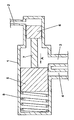
- An embodiment of the invention will now be described, by way of example only, with reference to the drawing which is a cross-sectional view of a pressure relief valve in accordance with an embodiment of the invention.
- The valve illustrated is suitable for use as a pressure relief valve in a typical lubrication system for an internal combustion engine and comprises a housing 1 having a cylindrical bore. Part of the bore has a diameter greater than the remaining portion thereof. At one end of the housing, and in the region of smaller diameter bore, there is provided a first inlet port 2 for receiving pilot pressure from an engine oil gallery. Part-way along the housing 1 in the region of larger diameter bore there is provided a second inlet port 3 for receiving oil from a pump outlet, and also an outlet port 4 which serves to vent excess oil to a sump or to the pump's suction side.
- Positioned within the bore is a piston assembly which comprises first and
second pistons 5, 6 joined together by a connecting rod 7. The assembly is biased by acoil spring 8. Thespring 8 is located in the region of larger diameter bore between an end wall of the housing and one face of thefirst piston 5. - The diameter of the
first piston 5 is substantially equal to that of the larger bore and is located so that it seals off the outlet port 4 from the second inlet port 3 when thespring 8 is relaxed, and allows fluid communication between these two ports when thespring 8 is compressed. - The diameter of the second piston 6 is substantially equal to that of the smaller bore and is located in the region of smaller diameter bore so that one of its faces is exposed to forces exerted by oil at the second inlet port 3 and its opposite face is exposed to forces exerted by oil at the first (pilot pressure) inlet port 2.
- Operation of the valve will now be described.
- As the piston 6 has a smaller diameter than the
piston 5, pump outlet pressure at port 3 will generate a resultant force in the direction of arrow A, causing thespring 8 to compress. At engine start-up, even if the pilot oil feed (from the engine gallery) has no pressure, the valve will be forced to open if this resultant force exceeds the pre-set spring force. Hence oil can vent through the outlet port 4. - Once pilot pressure has built up, the force on the
spring 8 will be the vector sum of the forces brought about by the pump outlet pressure on the twopistons 5, 6 and the pilot pressure on the smaller piston 6. Hence, the opening and closing of the valve can be controlled by pilot pressure to a lesser or greater degree depending on the choice of relative sizes of the twopistons 5, 6. - The valve illustrated can be used with any type of oil pump whether a fixed flow pump or a variable flow pump. It can also be used with a mechanical, hydraulic or electronic control circuit such as a two-stage pressure control system or a fully-variable pressure control system.
Claims (1)
- A pressure relief valve for a lubrication system, the valve comprising a housing (1) having a bore, first and second ends, an inlet port (3) and an outlet port (4) for, respectively, admitting lubricant from a high pressure side of the lubrication system into the bore and expelling it therefrom, a pilot pressure inlet port (2) at its first end for admitting lubricant taken from a point remote from said high pressure side, and a biasing member (8) and a piston assembly (5, 6, 7) located within the bore, the piston assembly comprising a first piston (5) biased against the second end of the housing by the biasing member (8) and a second piston (6) connected to the first piston (5) and having a smaller diameter than the first piston, wherein a face of the first piston (5) is exposed to pressure from lubricant entering the bore through the inlet port (3) and a face of the second piston (6) is exposed to pressure from lubricant entering the bore through the pilot pressure inlet port (2).
Applications Claiming Priority (1)
| Application Number | Priority Date | Filing Date | Title |
|---|---|---|---|
| GB0617369A GB0617369D0 (en) | 2006-09-02 | 2006-09-02 | Pressure relief valve |
Publications (3)
| Publication Number | Publication Date |
|---|---|
| EP1906069A2 true EP1906069A2 (en) | 2008-04-02 |
| EP1906069A3 EP1906069A3 (en) | 2011-11-09 |
| EP1906069B1 EP1906069B1 (en) | 2013-01-23 |
Family
ID=37137286
Family Applications (1)
| Application Number | Title | Priority Date | Filing Date |
|---|---|---|---|
| EP20070253364 Not-in-force EP1906069B1 (en) | 2006-09-02 | 2007-08-24 | Pressure relief valve |
Country Status (3)
| Country | Link |
|---|---|
| US (1) | US7775503B2 (en) |
| EP (1) | EP1906069B1 (en) |
| GB (1) | GB0617369D0 (en) |
Cited By (5)
| Publication number | Priority date | Publication date | Assignee | Title |
|---|---|---|---|---|
| CN102032015B (en) * | 2009-09-29 | 2012-10-03 | 湖南机油泵股份有限公司 | Oil expelling-preventing safe oil pump |
| CN103477133A (en) * | 2011-03-31 | 2013-12-25 | 麦格纳动力系有限公司 | Low gain pressure relief valve for a fluid pump |
| US9732979B2 (en) | 2010-12-31 | 2017-08-15 | Google Inc. | HVAC control system encouraging energy efficient user behaviors in plural interactive contexts |
| US10145577B2 (en) | 2012-03-29 | 2018-12-04 | Google Llc | User interfaces for HVAC schedule display and modification on smartphone or other space-limited touchscreen device |
| US10295974B2 (en) | 2011-10-07 | 2019-05-21 | Google Llc | Methods and graphical user interfaces for reporting performance information for an HVAC system controlled by a self-programming network-connected thermostat |
Families Citing this family (23)
| Publication number | Priority date | Publication date | Assignee | Title |
|---|---|---|---|---|
| US8870233B2 (en) * | 2007-07-03 | 2014-10-28 | S.P.M. Flow Control, Inc. | Swivel joint with uniform ball bearing requirements |
| CA2747707A1 (en) * | 2008-12-18 | 2010-07-15 | Weir Spm, Inc. | Hydraulic unloading valve |
| MX2011011007A (en) | 2009-04-20 | 2012-02-13 | Spm Flow Control Inc | Flowline flapper valve. |
| CA2767042C (en) | 2009-06-03 | 2017-08-15 | S.P.M. Flow Control, Inc. | Plug valve indicator |
| US9388804B2 (en) | 2011-01-28 | 2016-07-12 | Magna Powertrain Inc. | Oil pump with selectable outlet pressure |
| KR101294197B1 (en) | 2012-02-02 | 2013-08-08 | 기아자동차주식회사 | Relief valve for oil pump |
| CA2882169C (en) | 2012-08-16 | 2020-04-21 | S.P.M. Flow Control, Inc. | Plug valve having preloaded seal segments |
| US9322243B2 (en) | 2012-08-17 | 2016-04-26 | S.P.M. Flow Control, Inc. | Automated relief valve control system and method |
| US9273543B2 (en) | 2012-08-17 | 2016-03-01 | S.P.M. Flow Control, Inc. | Automated relief valve control system and method |
| JP2014081023A (en) * | 2012-10-16 | 2014-05-08 | Suzuki Motor Corp | Relief valve structure of oil pump |
| US9913957B2 (en) | 2012-12-05 | 2018-03-13 | Shenzhen Mindray Bio-Medical Electronics Co. Ltd. | Power switch for auxiliary common gas outlet |
| CN105228798B (en) * | 2013-02-26 | 2017-06-09 | 艾沛克斯品牌公司 | Active feed tool with modular structure |
| USD707332S1 (en) | 2013-03-15 | 2014-06-17 | S.P.M. Flow Control, Inc. | Seal assembly |
| USD707797S1 (en) | 2013-03-15 | 2014-06-24 | S.P.M. Flow Control, Inc. | Seal segment |
| WO2015002863A1 (en) | 2013-07-01 | 2015-01-08 | S.P.M. Flow Control, Inc. | Manifold assembly |
| WO2015089391A1 (en) * | 2013-12-13 | 2015-06-18 | Graco Minnesota Inc. | Adjustable restriction |
| GB2536251B (en) * | 2015-03-10 | 2020-09-16 | Concentric Birmingham Ltd | Recirculation valve |
| CA2989626C (en) | 2015-06-15 | 2023-08-29 | S.P.M. Flow Control, Inc. | Full-root-radius-threaded wing nut having increased wall thickness |
| US10677365B2 (en) | 2015-09-04 | 2020-06-09 | S.P.M. Flow Control, Inc. | Pressure relief valve assembly and methods |
| US10392977B2 (en) * | 2016-02-11 | 2019-08-27 | Slw Automotive Inc. | Automotive lubricant pumping system with two piece relief valve |
| JP2018091176A (en) * | 2016-11-30 | 2018-06-14 | 大豊工業株式会社 | Flow control valve |
| EP4334576A1 (en) | 2021-05-04 | 2024-03-13 | Cummins, Inc. | Engine lubrication systems, lubrication fluid circulation systems, and methods for regulating fluid pressure |
| CN118327807B (en) * | 2024-05-28 | 2024-11-15 | 杭州刚信科技有限公司 | A crankcase integrating PCV and oil-gas separation for new energy vehicles |
Family Cites Families (14)
| Publication number | Priority date | Publication date | Assignee | Title |
|---|---|---|---|---|
| US442492A (en) * | 1890-12-09 | Craven r | ||
| US378609A (en) * | 1888-02-28 | Air-pump governor | ||
| US1324705A (en) * | 1919-12-09 | Intake-tjitloadeb | ||
| US888062A (en) * | 1906-01-24 | 1908-05-19 | Isaac H Boyer | Boiler-furnace. |
| US962551A (en) * | 1906-12-26 | 1910-06-28 | Rudolph Conrader | Relief device. |
| GB594787A (en) * | 1944-02-24 | 1947-11-19 | Sulzer Freres Soclete Anonyme | Improvements relating to pressure responsive valves |
| US2778378A (en) * | 1952-07-28 | 1957-01-22 | Bendix Aviat Corp | Combination sequence and locking valve |
| US2890715A (en) * | 1955-08-26 | 1959-06-16 | Warner Swasey Co | Multi-pressure relief valve |
| US4145025A (en) | 1976-12-13 | 1979-03-20 | B. W. B. Controls, Inc. | Control device |
| US4838306A (en) * | 1987-08-10 | 1989-06-13 | Aladdin Engineering & Mfg., Inc. | Pneumatic locking valve with manual override |
| US5174335A (en) * | 1992-04-30 | 1992-12-29 | Kabushiki Kaisha Com. | Bidirectional vacuum valve |
| US6116272A (en) | 1999-03-26 | 2000-09-12 | Daimlerchrysler Coroporation | Debris resistant oil pressure relief valve |
| US6186750B1 (en) | 1999-04-27 | 2001-02-13 | Borgwarner, Inc. | Oil pump control valve spool with pilot pressure relief valve |
| DE102005050063A1 (en) * | 2005-10-19 | 2007-04-26 | Bayerische Motoren Werke Ag | Pressure control unit |
-
2006
- 2006-09-02 GB GB0617369A patent/GB0617369D0/en not_active Ceased
-
2007
- 2007-08-13 US US11/837,783 patent/US7775503B2/en not_active Expired - Fee Related
- 2007-08-24 EP EP20070253364 patent/EP1906069B1/en not_active Not-in-force
Non-Patent Citations (1)
| Title |
|---|
| None |
Cited By (8)
| Publication number | Priority date | Publication date | Assignee | Title |
|---|---|---|---|---|
| CN102032015B (en) * | 2009-09-29 | 2012-10-03 | 湖南机油泵股份有限公司 | Oil expelling-preventing safe oil pump |
| US9732979B2 (en) | 2010-12-31 | 2017-08-15 | Google Inc. | HVAC control system encouraging energy efficient user behaviors in plural interactive contexts |
| US10443879B2 (en) | 2010-12-31 | 2019-10-15 | Google Llc | HVAC control system encouraging energy efficient user behaviors in plural interactive contexts |
| CN103477133A (en) * | 2011-03-31 | 2013-12-25 | 麦格纳动力系有限公司 | Low gain pressure relief valve for a fluid pump |
| CN103477133B (en) * | 2011-03-31 | 2016-01-06 | 麦格纳动力系有限公司 | For the low gain pressure relief valve of fluid pump |
| US10295974B2 (en) | 2011-10-07 | 2019-05-21 | Google Llc | Methods and graphical user interfaces for reporting performance information for an HVAC system controlled by a self-programming network-connected thermostat |
| US10145577B2 (en) | 2012-03-29 | 2018-12-04 | Google Llc | User interfaces for HVAC schedule display and modification on smartphone or other space-limited touchscreen device |
| US11781770B2 (en) | 2012-03-29 | 2023-10-10 | Google Llc | User interfaces for schedule display and modification on smartphone or other space-limited touchscreen device |
Also Published As
| Publication number | Publication date |
|---|---|
| EP1906069A3 (en) | 2011-11-09 |
| EP1906069B1 (en) | 2013-01-23 |
| GB0617369D0 (en) | 2006-10-11 |
| US7775503B2 (en) | 2010-08-17 |
| US20080054204A1 (en) | 2008-03-06 |
Similar Documents
| Publication | Publication Date | Title |
|---|---|---|
| EP1906069B1 (en) | Pressure relief valve | |
| JP4280419B2 (en) | Sequence valve provided in a fuel injection system for an internal combustion engine | |
| EP2668379B1 (en) | Oil pump with selectable outlet pressure | |
| KR101481206B1 (en) | Fuel overflow valve for a fuel injection system, and fuel injection system having a fuel overflow valve | |
| US20060127229A1 (en) | Variable displacement pump and control therefor | |
| US9453440B2 (en) | Oil pump for internal combustion engine, and relief pressure control apparatus for oil pump | |
| US20100192898A1 (en) | Oil supply system for internal combustion engine with dual mode pressure limiting valve | |
| EP1712775A1 (en) | Fuel supply device | |
| US8430645B2 (en) | Two stage pressure regulation system for variable displacement hydraulic pumps | |
| EP2375083A2 (en) | Relief valve | |
| EP1310638A3 (en) | Engine breather system | |
| JP4887421B2 (en) | Supply pump for high-pressure gasoline fuel injection | |
| JP2005526204A (en) | Equipment for pressure regulation of hydraulic pumps | |
| US20160265679A1 (en) | Recirculation valve | |
| EP1956277A1 (en) | Valve | |
| EP3728825B1 (en) | High pressure fuel pump | |
| EP1806504A1 (en) | No-load operation system of tadem pump | |
| KR20180029078A (en) | Solenoid operated pressure relief valve | |
| WO2007122463A2 (en) | A pressure dissipater device for a hydraulic circuit | |
| US4953582A (en) | Combined pressure regulator and relief valve having a single biasing means | |
| KR101251267B1 (en) | Relief Valve | |
| KR20180050107A (en) | Relief valve for oil pump | |
| EP0853717A1 (en) | Device for limiting the oil pressure in the lubricating oil circuit of an internal combustion engine | |
| EP3674550B1 (en) | Two-stage variable relief valve for oil pump | |
| EP1777382A3 (en) | Pressure regulating unit |
Legal Events
| Date | Code | Title | Description |
|---|---|---|---|
| PUAI | Public reference made under article 153(3) epc to a published international application that has entered the european phase |
Free format text: ORIGINAL CODE: 0009012 |
|
| AK | Designated contracting states |
Kind code of ref document: A2 Designated state(s): AT BE BG CH CY CZ DE DK EE ES FI FR GB GR HU IE IS IT LI LT LU LV MC MT NL PL PT RO SE SI SK TR |
|
| AX | Request for extension of the european patent |
Extension state: AL BA HR MK YU |
|
| PUAL | Search report despatched |
Free format text: ORIGINAL CODE: 0009013 |
|
| AK | Designated contracting states |
Kind code of ref document: A3 Designated state(s): AT BE BG CH CY CZ DE DK EE ES FI FR GB GR HU IE IS IT LI LT LU LV MC MT NL PL PT RO SE SI SK TR |
|
| AX | Request for extension of the european patent |
Extension state: AL BA HR MK RS |
|
| RIC1 | Information provided on ipc code assigned before grant |
Ipc: F01M 1/16 20060101ALI20110930BHEP Ipc: F01M 13/00 20060101ALI20110930BHEP Ipc: F16K 17/04 20060101AFI20110930BHEP |
|
| 17P | Request for examination filed |
Effective date: 20120509 |
|
| AKX | Designation fees paid |
Designated state(s): AT DE GB |
|
| 17Q | First examination report despatched |
Effective date: 20120621 |
|
| GRAP | Despatch of communication of intention to grant a patent |
Free format text: ORIGINAL CODE: EPIDOSNIGR1 |
|
| GRAS | Grant fee paid |
Free format text: ORIGINAL CODE: EPIDOSNIGR3 |
|
| GRAA | (expected) grant |
Free format text: ORIGINAL CODE: 0009210 |
|
| AK | Designated contracting states |
Kind code of ref document: B1 Designated state(s): AT DE GB |
|
| REG | Reference to a national code |
Ref country code: GB Ref legal event code: FG4D |
|
| REG | Reference to a national code |
Ref country code: AT Ref legal event code: REF Ref document number: 595162 Country of ref document: AT Kind code of ref document: T Effective date: 20130215 |
|
| REG | Reference to a national code |
Ref country code: DE Ref legal event code: R096 Ref document number: 602007028196 Country of ref document: DE Effective date: 20130321 |
|
| PLBE | No opposition filed within time limit |
Free format text: ORIGINAL CODE: 0009261 |
|
| STAA | Information on the status of an ep patent application or granted ep patent |
Free format text: STATUS: NO OPPOSITION FILED WITHIN TIME LIMIT |
|
| 26N | No opposition filed |
Effective date: 20131024 |
|
| REG | Reference to a national code |
Ref country code: DE Ref legal event code: R097 Ref document number: 602007028196 Country of ref document: DE Effective date: 20131024 |
|
| REG | Reference to a national code |
Ref country code: DE Ref legal event code: R082 Ref document number: 602007028196 Country of ref document: DE Representative=s name: DOERFLER, THOMAS, DR.-ING., DE |
|
| PGFP | Annual fee paid to national office [announced via postgrant information from national office to epo] |
Ref country code: GB Payment date: 20190728 Year of fee payment: 13 Ref country code: AT Payment date: 20190726 Year of fee payment: 13 |
|
| PGFP | Annual fee paid to national office [announced via postgrant information from national office to epo] |
Ref country code: DE Payment date: 20200713 Year of fee payment: 14 |
|
| REG | Reference to a national code |
Ref country code: AT Ref legal event code: MM01 Ref document number: 595162 Country of ref document: AT Kind code of ref document: T Effective date: 20200824 |
|
| GBPC | Gb: european patent ceased through non-payment of renewal fee |
Effective date: 20200824 |
|
| PG25 | Lapsed in a contracting state [announced via postgrant information from national office to epo] |
Ref country code: AT Free format text: LAPSE BECAUSE OF NON-PAYMENT OF DUE FEES Effective date: 20200824 |
|
| PG25 | Lapsed in a contracting state [announced via postgrant information from national office to epo] |
Ref country code: GB Free format text: LAPSE BECAUSE OF NON-PAYMENT OF DUE FEES Effective date: 20200824 |
|
| REG | Reference to a national code |
Ref country code: DE Ref legal event code: R119 Ref document number: 602007028196 Country of ref document: DE |
|
| PG25 | Lapsed in a contracting state [announced via postgrant information from national office to epo] |
Ref country code: DE Free format text: LAPSE BECAUSE OF NON-PAYMENT OF DUE FEES Effective date: 20220301 |