EP1906020A2 - Flüssigkeitspumpe mit regelbarem Fördervolumen - Google Patents
Flüssigkeitspumpe mit regelbarem Fördervolumen Download PDFInfo
- Publication number
- EP1906020A2 EP1906020A2 EP07014377A EP07014377A EP1906020A2 EP 1906020 A2 EP1906020 A2 EP 1906020A2 EP 07014377 A EP07014377 A EP 07014377A EP 07014377 A EP07014377 A EP 07014377A EP 1906020 A2 EP1906020 A2 EP 1906020A2
- Authority
- EP
- European Patent Office
- Prior art keywords
- adjusting piston
- housing
- liquid pump
- piston
- axially
- Prior art date
- Legal status (The legal status is an assumption and is not a legal conclusion. Google has not performed a legal analysis and makes no representation as to the accuracy of the status listed.)
- Granted
Links
Images
Classifications
-
- F—MECHANICAL ENGINEERING; LIGHTING; HEATING; WEAPONS; BLASTING
- F04—POSITIVE - DISPLACEMENT MACHINES FOR LIQUIDS; PUMPS FOR LIQUIDS OR ELASTIC FLUIDS
- F04C—ROTARY-PISTON, OR OSCILLATING-PISTON, POSITIVE-DISPLACEMENT MACHINES FOR LIQUIDS; ROTARY-PISTON, OR OSCILLATING-PISTON, POSITIVE-DISPLACEMENT PUMPS
- F04C2/00—Rotary-piston machines or pumps
- F04C2/08—Rotary-piston machines or pumps of intermeshing-engagement type, i.e. with engagement of co-operating members similar to that of toothed gearing
- F04C2/12—Rotary-piston machines or pumps of intermeshing-engagement type, i.e. with engagement of co-operating members similar to that of toothed gearing of other than internal-axis type
- F04C2/14—Rotary-piston machines or pumps of intermeshing-engagement type, i.e. with engagement of co-operating members similar to that of toothed gearing of other than internal-axis type with toothed rotary pistons
- F04C2/18—Rotary-piston machines or pumps of intermeshing-engagement type, i.e. with engagement of co-operating members similar to that of toothed gearing of other than internal-axis type with toothed rotary pistons with similar tooth forms
-
- F—MECHANICAL ENGINEERING; LIGHTING; HEATING; WEAPONS; BLASTING
- F04—POSITIVE - DISPLACEMENT MACHINES FOR LIQUIDS; PUMPS FOR LIQUIDS OR ELASTIC FLUIDS
- F04C—ROTARY-PISTON, OR OSCILLATING-PISTON, POSITIVE-DISPLACEMENT MACHINES FOR LIQUIDS; ROTARY-PISTON, OR OSCILLATING-PISTON, POSITIVE-DISPLACEMENT PUMPS
- F04C14/00—Control of, monitoring of, or safety arrangements for, machines, pumps or pumping installations
- F04C14/18—Control of, monitoring of, or safety arrangements for, machines, pumps or pumping installations characterised by varying the volume of the working chamber
- F04C14/185—Control of, monitoring of, or safety arrangements for, machines, pumps or pumping installations characterised by varying the volume of the working chamber by varying the useful pumping length of the cooperating members in the axial direction
Definitions
- the invention relates to a liquid pump with adjustable delivery volume, according to the preamble of claim 1.
- a generic liquid pump is from the DE 102 22 134 B4 known.
- a problem of such liquid pumps is that act on the adjusting piston, for example as a result of pressure pulsations alternating forces that lead to both wear of the bearing of the Sekundärpumpenrades on the adjusting piston and wear of the abutting contact surface of the adjusting piston and the counter surface of the housing. Both affect the life of the pump. In addition, the alternating stresses can lead to undesirable noise.
- the invention has for its object to further develop a generic liquid pump such that at reduced noise their life is improved.
- the inventive bias of the adjusting piston in the direction of rotation about its axis rotatory alternating stresses of the adjusting are reduced, in particular overcompensated, so that the contact surface of the adjusting is constantly in well-defined system on the opposite surface of the housing.
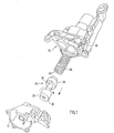
- a liquid pump 2 has housing parts 10, 12 which can be tightly screwed together and form between them a delivery chamber 14 which has the contour of two overlapping circles in cross-section and which has an inlet 16 (FIG. 2) with an outlet formed on the housing 18 connects.
- a primary pump wheel 20 is arranged, which is provided with external teeth whose teeth, for example, are straight or obliquely toothed and extend approximately parallel to the axis.
- the outer contour 22 of the Primärpumpenrades corresponds to the inner contour of the associated part of the delivery chamber 14.
- the Primärpumpenrad 20 is rotatably connected to a shaft 24 which is mounted in the housing 10, 12 and is rotatably driven from outside the housing.
- an adjusting piston 26 is axially slidably received in the housing 10, 12, the end each having a piston flange 28, 30, wherein the piston flanges 28, 30 are connected by a shaft 32 rigidly together.
- the adjusting piston 26 is a total of a built part, so that on its shaft 32, a Sekundärpumpenrad 34 is rotatably storable, whose outer contour corresponds to the right lower portion of the conveying chamber 14 and which is provided with an outer toothing, which is connected to the external toothing of the Primärpumpenrades 20th meshes or is engaged.
- bores are formed such that therein the piston flanges 28 and 30 are largely axially accurate fit.
- the end face of the piston flange 28 is supported on a helical spring 36, which is received in a corresponding housing bore and is supported on the bottom of a lid closing the bore.
- the piston flange 30 is provided on its peripheral surface with a recess 38 whose contour of the outer contour 22 of the Primärpumpenrades 20 corresponds.
- the intended for receiving the piston flange 30 bore in the housing part 12 is not circular. Its cross-section corresponds rather to the cross-section of the piston flange 30, so that the adjusting piston 26 in the housing 10, 12 is received axially displaceable and simultaneously unrotatable.
- the piston flange 30 corresponding bore in the housing part 12 may be acted upon, for example, with hydraulic pressure, so that the adjusting piston against the force of the spring 36 is hineinbewegbar in the housing part 10. This reduces the axial length along which the external threads of the pump wheels are engaged and thus the delivery volume of the pump.
- the coil spring 36 is at its two end faces with bent webs 40 (only one of the webs 40 is visible) provided in the corresponding Slots in the end face of the piston flange 28 and the bottom of the bore, not shown, are received in the housing part 10, so that the coil spring 36 is held against rotation. Due to the bias or deformation experienced by the coil spring 36 during assembly of the pump, the two end webs 40 are rotated relative to each other, whereby the rotatably guided on the housing part 12 adjusting piston is biased in the direction of rotation. As a result of this bias of the adjusting piston 26 is even at fluctuating forces in well-defined system on the housing part 12, so that wear of contact surfaces and mating surfaces is reduced and any games exploiting motion amplitudes occur that can lead to unwanted noise.
- adjusting piston 26 For axial adjustment of the adjusting piston 26 can be provided in both housing parts with hydraulic fluid acted cylinder chambers. The adjustment can also be done mechanically, for example by means of an electric motor.
- the rotationally fixed guidance of the adjusting piston on the housing can be done by any other suitable means.
- the invention is suitable for use in oil pumps of internal combustion engines.
Landscapes
- Engineering & Computer Science (AREA)
- Mechanical Engineering (AREA)
- General Engineering & Computer Science (AREA)
- Reciprocating Pumps (AREA)
- Structures Of Non-Positive Displacement Pumps (AREA)
Abstract
Description
- Die Erfindung betrifft eine Flüssigkeitspumpe mit regelbarem Fördervolumen, gemäß dem Oberbegriff des Anspruchs 1.
- Eine gattungsgemäße Flüssigkeitspumpe ist aus der
DE 102 22 134 B4 bekannt. Ein Problem solcher Flüssigkeitspumpen liegt darin, dass auf den Verstellkolben beispielsweise infolge von Druckpulsationen Wechselkräfte wirken, die sowohl zu einem Verschleiß der Lagerung des Sekundärpumpenrades auf dem Verstellkolben als auch zu einem Verschleiß der in gegenseitiger Anlage befindlichen Anlagefläche des Verstellkolbens und der Gegenfläche des Gehäuses führen. Beides beeinträchtigt die Lebensdauer der Pumpe. Außerdem können die Wechselbeanspruchungen zu unerwünschter Geräuschentwicklung führen. - Der Erfindung liegt die Aufgabe zugrunde, eine gattungsgemäße Flüssigkeitspumpe derart weiterzuentwickeln, dass bei verminderter Geräuschentwicklung deren Lebensdauer verbessert ist.
- Diese Aufgabe wird mit einer Flüssigkeitspumpe gemäß dem Anspruch 1 gelöst.
- Durch die erfindungsgemäße Vorspannung des Verstellkolbens in Richtung einer Drehung um seine Achse werden rotatorische Wechselbeanspruchungen des Verstellkolbens vermindert, insbesondere überkompensiert, so dass die Anlagefläche des Verstellkolbens sich ständig in wohl definierter Anlage an der Gegenfläche des Gehäuses befindet.
- Die Unteransprüche sind auf vorteilhafte Weiterbildungen der erfindungsgemäßen Flüssigkeitspumpe gerichtet, die gemäß dem Anspruch 5 vorteilhafter Weise als Ölpumpe einer Brennkraftmaschine ausgebildet ist.
- Die Erfindung wird im Folgenden anhand schematischer Zeichnungen beispielsweise und mit weiteren Einzelheiten erläutert.
- In den Figuren stellen dar:
- Fig. 1
- eine perspektivische Ansicht der erfindungsgemäßen Flüssigkeitspumpe in auseinander gezogener Darstellung,
- Fig. 2
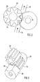
- eine Stirnansicht des Primärpumpenrades und des Verstellkolbens und
- Fig. 3
- eine perspektivische Ansicht des Primärpumpenrades und des Sekundärpumpenrades.
- Gemäß den Figuren weist eine Flüssigkeitspumpe 2 miteinander dicht verschraubbare Gehäuseteile 10, 12 auf, die zwischen sich eine Förderkammer 14 bilden, die im Querschnitt die Kontur zweier sich überlappender Kreise aufweist und die einen am Gehäuse ausgebildeten Einlass 16 (Fig. 2) mit einem Auslass 18 verbindet. In dem gemäß den Figuren linken oberen Bereich der Förderkammer ist ein Primärpumpenrad 20 angeordnet, das mit einer Außenverzahnung versehen ist, dessen Zähne beispielsweise gerade oder schräg verzahnt sind etwa achsparallel verlaufen. Der Außenkontur 22 des Primärpumpenrades entspricht der Innenkontur des zugehörigen Teils der Förderkammer 14. Das Primärpumpenrad 20 ist drehfest mit einer Welle 24 verbunden, die in dem Gehäuse 10, 12 gelagert ist und von außerhalb des Gehäuses drehantreibbar ist.
- Weiter ist in dem Gehäuse 10, 12 ein Verstellkolben 26 axial verschiebbar aufgenommen, der endseitig je einen Kolbenflansch 28, 30 aufweist, wobei die Kolbenflansche 28, 30 mittels eines Schaftes 32 starr miteinander verbunden sind. Der Verstellkolben 26 ist insgesamt ein gebautes Teil, so dass auf seinem Schaft 32 ein Sekundärpumpenrad 34 drehbar lagerbar ist, dessen Außenkontur dem gemäß den Figuren rechten unteren Bereich der Förderkammer 14 entspricht und das mit einer Außenverzahnung versehen ist, die mit der Außenverzahnung des Primärpumpenrades 20 kämmt bzw. in Eingriff ist. In dem Gehäuseteil 10 und Gehäuseteil 12 sind Bohrungen derart ausgebildet, dass darin die Kolbenflansche 28 bzw. 30 weitgehend passgenau axial beweglich sind.
- Die Stirnseite des Kolbenflansches 28 stützt sich an einer Schraubenfeder 36 ab, die in einer entsprechenden Gehäusebohrung aufgenommen ist und sich am Boden eines die Bohrung verschließenden Deckels abstützt. Damit der Verstellkolben 26 gegen die Kraft der Feder 36 in den Gehäuseteil 10 hineinbewegbar ist, ist der Kolbenflansch 30 an seiner Umfangsfläche mit einer Ausnehmung 38 versehen, deren Kontur der Außenkontur 22 des Primärpumpenrades 20 entspricht. Die zur Aufnahme des Kolbenflansches 30 vorgesehene Bohrung im Gehäuseteil 12 ist nicht kreisrund. Ihr Querschnitt entspricht vielmehr dem Querschnitt des Kolbenflansches 30, so dass der Verstellkolben 26 in dem Gehäuse 10, 12 axial verschiebbar und gleichzeitig unverdrehbar aufgenommen ist.
- Zur Verstellung des Verstellkolbens 26 kann die dem Kolbenflansch 30 entsprechende Bohrung im Gehäuseteil 12 beispielsweise mit Hydraulikdruckmittel beaufschlagt werden, so dass der Verstellkolben gegen die Kraft der Feder 36 in den Gehäusteil 10 hineinbewegbar ist. Dabei vermindert sich die axiale Länge, längs der die Außengewinde der Pumpenräder in Eingriff sind und somit das Fördervolumen der Pumpe.
- Die bisher beschriebene Anordnung ist in ihrem Aufbau an sich bekannt und wird daher nicht im Einzelnen erläutert.
- Auf den Verstellkolben wirken im Betrieb der Pumpe die in Fig. 1 durch dicke Pfeile dargestellten Kräfte, nämlich die Vorspannkraft der Feder 36 und infolge der Reibung des Sekundärpumpenrades auf dem Schaft 32 eine Kraft in Umfangsrichtung, die das Bestreben hat, den Verstellkolben um seine Achse zu drehen. Außerdem wirkt auf den Verstellkolben noch eine Kraft von der Achse des Primärpumpenrades 20 her, die durch den Druck der zwischen den Zähnen geförderten Flüssigkeit bedingt ist. Diese Kräfte fluktuieren und führen dazu, dass Verschleiß an der Außenumfangsfläche der Kolbenflanschen 30 und/oder der Gegenfläche des Gehäuses auftritt bzw., wenn keine vollflächige Anlage erzielt wird, Verschleiß zwischen dem Kolbenflansch 30 und am Gehäuse ausgebildeten Anschlägen auftritt, die den Verstellkolben drehfest halten. Es versteht sich, dass sowohl die Passung des Verstellkolbens in den Bohrungen des Gehäuses als auch die radial und axiale Führung des Sekundärpumpenrades an dem Verstellkolben nicht vollständig spielfrei sind.
- Um ständig eine spielfreie Anlage des Verstellkolben an einer seiner Verdrehbarkeit hindernden Gegenfläche zu gewährleisten, ist die Schraubenfeder 36 an ihren beiden Stirnseiten mit abgebogenen Stegen 40 (nur einer der Stege 40 ist sichtbar) versehen, die in entsprechenden Schlitzen in der Stirnseite des Kolbenflansches 28 und dem Boden der nicht dargestellten Bohrung im Gehäuseteil 10 aufgenommen sind, so dass die Schraubenfeder 36 drehfest gehalten ist. Durch die Vorspannung bzw. Verformung, die die Schraubenfeder 36 beim Zusammenbau der Pumpe erfährt, werden die beiden stirnseitigen Stege 40 relativ zueinander verdreht, wodurch der am Gehäuseteil 12 drehfest geführte Verstellkolben in Drehrichtung vorgespannt wird. Infolge dieser Vorspannung ist der Verstellkolben 26 auch bei fluktuierenden Kräften in wohl definierter Anlage am Gehäuseteil 12, so dass ein Verschleiß von Anlageflächen und Gegenflächen vermindert ist und keine etwaige Spiele ausnutzenden Bewegungsamplituden vorkommen, die zu unerwünschter Geräuschentwicklung führen können.
- Die beispielhaft geschilderte Erfindung kann vielfältig abgeändert werden:
- Anstelle der Stege 42 kann die Schraubenfeder auch axial gerichtete Enden aufweisen, die in entsprechende Löcher der Gegenflächen eingreifen. Weiter kann zusätzlich zur der Schraubenfeder eine Torsionsfeder vorgesehen sein, die den Verstellkolben in Drehrichtung vorspannt. Die Richtung der Drehung, in die vorgespannt wird, stimmt vorteilhafterweise mit der Drehrichtung des Sekundärpumpenrades 34 überein, von dem in Fig. 2 nur die die Anlagefläche 40 überragenden Zähne sichtbar sind.
- Zur Axialverstellung des Verstellkolbens 26 können in beiden Gehäuseteilen mit Hydraulikmittel beaufschlagte Zylinderräume vorgesehen sein. Die Verstellung kann auch mechanisch, beispielsweise mittels eines Elektromotors, erfolgen.
- Die drehfeste Führung des Verstellkolbens am Gehäuse kann über jedwelche andere geeigneten Mittel erfolgen.
- Besonders vorteilhaft eignet sich die Erfindung zur Verwendung in Ölpumpen von Brennkraftmaschinen.
-
- 10
- Gehäuseteil
- 12
- Gehäuseteil
- 14
- Förderkammer
- 16
- Einlass
- 18
- Auslass
- 20
- Primärpumpenrad
- 22
- Außenkontur
- 24
- Welle
- 26
- Verstellkolben
- 28
- Kolbenflansch
- 30
- Kolbenflansch
- 32
- Schaft
- 34
- Sekundärpumpenrad
- 36
- Feder
- 38
- Ausnehmung
- 40
- Steg
Claims (6)
- Flüssigkeitspumpe mit regelbarem Fördervolumen, enthaltend
ein Gehäuse (10, 12) mit ein Einlass und einem Auslass und einer den Einlass mit dem Auslass verbindenden Förderkammer (14), und
ein drehangetriebenes, axial festes Primärpumpenrad (20) mit einer Umfangsverzahnung, die mit der Umfangsverzahnung eines Sekundärpumpenrades (34) zur Förderung von Flüssigkeit vom Einlass zum Auslass in Eingriff ist, wobei
das Sekundärpumpenrad auf einem Verstellkolben (26) relativ zum Verstellkolben im Wesentlichen axial unverrückbar drehbar gelagert ist, welcher Verstellkolben an dem Gehäuse drehfest und axial verschiebbar angebracht und die in Anlage axial derart bewegbar ist, dass sich eine axiale Eingriffslänge der Umfangsverzahnungen ändert,
dadurch gekennzeichnet, dass der Verstellkolben (26) in Richtung einer Drehung um seine Achse vorgespannt ist. - Flüssigkeitspumpe nach Anspruch 1, dadurch gekennzeichnet, dass der Verstellkolben (26) für eine Drehung in Drehrichtung des Sekundärpumpenrades (34) vorgespannt ist.
- Flüssigkeitspumpe nach Anspruch 1 oder 2, dadurch gekennzeichnet, dass der Verstellkolben (26) gegen die Kraft einer sich zwischen einer Stirnseite eines der Kolbenflansche (28, 30) und dem Gehäuse (10, 12) abstützenden, vorgespannten Feder (36) axial verstellbar ist, wobei die Feder derart gebaut und an der Stirnfläche und dem Gehäuse gehalten ist, dass sie infolge ihrer Vorspannung den Verstellkolben in Richtung einer Drehung um seine Achse vorspannt.
- Flüssigkeitspumpe nach Anspruch 3, dadurch gekennzeichnet, dass die Feder (36) eine Schraubenfeder ist, die sich am Boden einer Gehäusebohrung und der Stirnfläche des Kolbenflansches (28) abstützt und an ihren Abstützstellen drehfest gehalten ist.
- Flüssigkeitspumpe nach einem der Ansprüche 1 bis 4, dadurch gekennzeichnet, dass die Pumpe als Außenzahnradpumpe ausgebildet ist.
- Flüssigkeitspumpe nach einem der Ansprüche 1 bis 5, dadurch gekennzeichnet, dass die Flüssigkeitspumpe eine Ölpumpe einer Brennkraftmaschine ist.
Applications Claiming Priority (1)
| Application Number | Priority Date | Filing Date | Title |
|---|---|---|---|
| DE200610044810 DE102006044810A1 (de) | 2006-09-22 | 2006-09-22 | Flüssigkeitspumpe mit regelbarem Fördervolumen |
Publications (3)
| Publication Number | Publication Date |
|---|---|
| EP1906020A2 true EP1906020A2 (de) | 2008-04-02 |
| EP1906020A3 EP1906020A3 (de) | 2009-11-18 |
| EP1906020B1 EP1906020B1 (de) | 2011-03-16 |
Family
ID=38727935
Family Applications (1)
| Application Number | Title | Priority Date | Filing Date |
|---|---|---|---|
| EP20070014377 Not-in-force EP1906020B1 (de) | 2006-09-22 | 2007-07-21 | Flüssigkeitspumpe mit regelbarem Fördervolumen |
Country Status (3)
| Country | Link |
|---|---|
| EP (1) | EP1906020B1 (de) |
| DE (2) | DE102006044810A1 (de) |
| ES (1) | ES2359085T3 (de) |
Family Cites Families (3)
| Publication number | Priority date | Publication date | Assignee | Title |
|---|---|---|---|---|
| DE10222131C5 (de) * | 2002-05-17 | 2011-08-11 | Schwäbische Hüttenwerke Automotive GmbH & Co. KG, 73433 | Verdrängerpumpe mit Fördervolumenverstellung |
| DE102004002062A1 (de) * | 2004-01-15 | 2005-08-04 | Volkswagen Ag | Zahnradpumpe mit Fördermengenregelung |
| DE102004028830A1 (de) * | 2004-06-15 | 2005-12-29 | Zf Friedrichshafen Ag | Zahnradmaschine |
-
2006
- 2006-09-22 DE DE200610044810 patent/DE102006044810A1/de not_active Withdrawn
-
2007
- 2007-07-21 EP EP20070014377 patent/EP1906020B1/de not_active Not-in-force
- 2007-07-21 ES ES07014377T patent/ES2359085T3/es active Active
- 2007-07-21 DE DE200750006717 patent/DE502007006717D1/de active Active
Also Published As
| Publication number | Publication date |
|---|---|
| ES2359085T3 (es) | 2011-05-18 |
| EP1906020A3 (de) | 2009-11-18 |
| DE502007006717D1 (de) | 2011-04-28 |
| EP1906020B1 (de) | 2011-03-16 |
| DE102006044810A1 (de) | 2008-03-27 |
Similar Documents
| Publication | Publication Date | Title |
|---|---|---|
| DE102011120162A1 (de) | Verbrennungskraftmaschine mit variabler Verdichtung | |
| WO2003051702A1 (de) | Elektrische hilfskraftlenkung für kraftfahrzeuge | |
| EP1305523B1 (de) | Innenzahnradpumpe | |
| DE10351223B4 (de) | Nockenwellenverstelleinrichtung für Fahrzeuge, vorzugsweise für Kraftfahrzeuge | |
| EP2299071B1 (de) | Vorrichtung zur Veränderung einer relativen Drehwinkellage einer Nockenwelle gegenüber einer Kurbelwelle einer Brennkraftmaschine | |
| DE9203378U1 (de) | Ölpumpe, insbesondere für eine Kettensäge | |
| DE3912965A1 (de) | Aggregat zum foerdern von kraftstoff | |
| DE10353027A1 (de) | Regelbare Pumpe, insbesondere Flügelzellenpumpe | |
| EP3054161B1 (de) | Verfahren zum betreiben einer zahnradpumpe und zahnradpumpe | |
| WO2008055745A1 (de) | Nockenwellentrieb mit einer geometrischen laufrollenstabilisierung | |
| DE102009042227A1 (de) | Vorrichtung zur Veränderung der relativen Winkellage einer Nockenwelle gegenüber einer Kurbelwelle einer Brennkraftmaschine | |
| DE4214752C2 (de) | Ölpumpe | |
| DE10337847A1 (de) | Pumpenanordnung mit einer Hochdruckpumpe und einer dieser vorgeschalteten Niederdruckpumpe für eine Kraftstoffeinspritzeinrichtung einer Brennkraftmaschine | |
| EP2494157A1 (de) | Nockenwellenverstellanordnung | |
| DE102010005603B4 (de) | Nockenwellenverstellanordnung mit einem als Wälzlager ausgebildetem Nockenwellenlager | |
| EP1209359A2 (de) | Zahnradförderpumpe | |
| EP1906020B1 (de) | Flüssigkeitspumpe mit regelbarem Fördervolumen | |
| DE102009047610A1 (de) | Außenzahnradpumpe | |
| EP1311762B1 (de) | Innenzahnradpumpe | |
| DE4315432A1 (de) | Aggregat zum Fördern von Kraftstoff aus einem Vorratstank zur Brennkraftmaschine eines Kraftfahrzeugs | |
| DE102006025367B4 (de) | Zahnradpumpe, insbesondere Zahnradölpumpe für Fahrzeuge | |
| WO2004048768A1 (de) | Pumpenanordnung mit einer hochdruckpumpe und einer dieser vorgeschalteten niederdruckpumpe für eine kraftstoffeinspritzeinrichtung einer brennkraftmaschine | |
| WO2001036820A9 (de) | Hydraulische kolbenpumpe | |
| DE3624382A1 (de) | Exzentrische sperrschieberpumpe, insbesondere zur foerderung von schmierstoffen fuer antriebe | |
| DE102019109536B4 (de) | Nockenwellenversteller vom Flügelzellentyp |
Legal Events
| Date | Code | Title | Description |
|---|---|---|---|
| PUAI | Public reference made under article 153(3) epc to a published international application that has entered the european phase |
Free format text: ORIGINAL CODE: 0009012 |
|
| AK | Designated contracting states |
Kind code of ref document: A2 Designated state(s): AT BE BG CH CY CZ DE DK EE ES FI FR GB GR HU IE IS IT LI LT LU LV MC MT NL PL PT RO SE SI SK TR |
|
| AX | Request for extension of the european patent |
Extension state: AL BA HR MK YU |
|
| PUAL | Search report despatched |
Free format text: ORIGINAL CODE: 0009013 |
|
| AK | Designated contracting states |
Kind code of ref document: A3 Designated state(s): AT BE BG CH CY CZ DE DK EE ES FI FR GB GR HU IE IS IT LI LT LU LV MC MT NL PL PT RO SE SI SK TR |
|
| AX | Request for extension of the european patent |
Extension state: AL BA HR MK RS |
|
| 17P | Request for examination filed |
Effective date: 20091210 |
|
| AKX | Designation fees paid |
Designated state(s): DE ES FR GB IT |
|
| GRAP | Despatch of communication of intention to grant a patent |
Free format text: ORIGINAL CODE: EPIDOSNIGR1 |
|
| GRAC | Information related to communication of intention to grant a patent modified |
Free format text: ORIGINAL CODE: EPIDOSCIGR1 |
|
| GRAS | Grant fee paid |
Free format text: ORIGINAL CODE: EPIDOSNIGR3 |
|
| GRAA | (expected) grant |
Free format text: ORIGINAL CODE: 0009210 |
|
| AK | Designated contracting states |
Kind code of ref document: B1 Designated state(s): DE ES FR GB IT |
|
| REG | Reference to a national code |
Ref country code: GB Ref legal event code: FG4D Free format text: NOT ENGLISH |
|
| REF | Corresponds to: |
Ref document number: 502007006717 Country of ref document: DE Date of ref document: 20110428 Kind code of ref document: P |
|
| REG | Reference to a national code |
Ref country code: DE Ref legal event code: R096 Ref document number: 502007006717 Country of ref document: DE Effective date: 20110428 |
|
| REG | Reference to a national code |
Ref country code: ES Ref legal event code: FG2A Ref document number: 2359085 Country of ref document: ES Kind code of ref document: T3 Effective date: 20110506 |
|
| PLBE | No opposition filed within time limit |
Free format text: ORIGINAL CODE: 0009261 |
|
| STAA | Information on the status of an ep patent application or granted ep patent |
Free format text: STATUS: NO OPPOSITION FILED WITHIN TIME LIMIT |
|
| 26N | No opposition filed |
Effective date: 20111219 |
|
| REG | Reference to a national code |
Ref country code: DE Ref legal event code: R097 Ref document number: 502007006717 Country of ref document: DE Effective date: 20111219 |
|
| REG | Reference to a national code |
Ref country code: FR Ref legal event code: PLFP Year of fee payment: 10 |
|
| REG | Reference to a national code |
Ref country code: FR Ref legal event code: PLFP Year of fee payment: 11 |
|
| REG | Reference to a national code |
Ref country code: FR Ref legal event code: PLFP Year of fee payment: 12 |
|
| PGFP | Annual fee paid to national office [announced via postgrant information from national office to epo] |
Ref country code: IT Payment date: 20190723 Year of fee payment: 13 Ref country code: FR Payment date: 20190724 Year of fee payment: 13 Ref country code: DE Payment date: 20190717 Year of fee payment: 13 Ref country code: ES Payment date: 20190822 Year of fee payment: 13 |
|
| PGFP | Annual fee paid to national office [announced via postgrant information from national office to epo] |
Ref country code: GB Payment date: 20190725 Year of fee payment: 13 |
|
| REG | Reference to a national code |
Ref country code: DE Ref legal event code: R119 Ref document number: 502007006717 Country of ref document: DE |
|
| GBPC | Gb: european patent ceased through non-payment of renewal fee |
Effective date: 20200721 |
|
| PG25 | Lapsed in a contracting state [announced via postgrant information from national office to epo] |
Ref country code: GB Free format text: LAPSE BECAUSE OF NON-PAYMENT OF DUE FEES Effective date: 20200721 Ref country code: FR Free format text: LAPSE BECAUSE OF NON-PAYMENT OF DUE FEES Effective date: 20200731 |
|
| PG25 | Lapsed in a contracting state [announced via postgrant information from national office to epo] |
Ref country code: DE Free format text: LAPSE BECAUSE OF NON-PAYMENT OF DUE FEES Effective date: 20210202 |
|
| PG25 | Lapsed in a contracting state [announced via postgrant information from national office to epo] |
Ref country code: IT Free format text: LAPSE BECAUSE OF NON-PAYMENT OF DUE FEES Effective date: 20200721 |
|
| REG | Reference to a national code |
Ref country code: ES Ref legal event code: FD2A Effective date: 20211230 |
|
| PG25 | Lapsed in a contracting state [announced via postgrant information from national office to epo] |
Ref country code: ES Free format text: LAPSE BECAUSE OF NON-PAYMENT OF DUE FEES Effective date: 20200722 |
|
| P01 | Opt-out of the competence of the unified patent court (upc) registered |
Effective date: 20230502 |