EP1905937A2 - Vorrichtung zum stabil miteinander Verbinden von profilierten Elementen - Google Patents
Vorrichtung zum stabil miteinander Verbinden von profilierten Elementen Download PDFInfo
- Publication number
- EP1905937A2 EP1905937A2 EP07110139A EP07110139A EP1905937A2 EP 1905937 A2 EP1905937 A2 EP 1905937A2 EP 07110139 A EP07110139 A EP 07110139A EP 07110139 A EP07110139 A EP 07110139A EP 1905937 A2 EP1905937 A2 EP 1905937A2
- Authority
- EP
- European Patent Office
- Prior art keywords
- profiled
- inserts
- profiled element
- elements
- plates
- Prior art date
- Legal status (The legal status is an assumption and is not a legal conclusion. Google has not performed a legal analysis and makes no representation as to the accuracy of the status listed.)
- Withdrawn
Links
- 238000004873 anchoring Methods 0.000 claims abstract description 11
- 239000000463 material Substances 0.000 claims description 6
- 239000000853 adhesive Substances 0.000 claims description 4
- 230000001070 adhesive effect Effects 0.000 claims description 4
- 230000000295 complement effect Effects 0.000 claims description 2
- 230000013011 mating Effects 0.000 claims description 2
- 230000000284 resting effect Effects 0.000 claims 2
- 230000008878 coupling Effects 0.000 description 3
- 238000010168 coupling process Methods 0.000 description 3
- 238000005859 coupling reaction Methods 0.000 description 3
- 238000003466 welding Methods 0.000 description 3
- 230000004308 accommodation Effects 0.000 description 1
- 239000007767 bonding agent Substances 0.000 description 1
- 239000002131 composite material Substances 0.000 description 1
- 239000000428 dust Substances 0.000 description 1
- 230000008595 infiltration Effects 0.000 description 1
- 238000001764 infiltration Methods 0.000 description 1
- 238000003780 insertion Methods 0.000 description 1
- 230000037431 insertion Effects 0.000 description 1
- 230000000670 limiting effect Effects 0.000 description 1
- 238000000034 method Methods 0.000 description 1
- 238000012986 modification Methods 0.000 description 1
- 230000004048 modification Effects 0.000 description 1
- 239000002023 wood Substances 0.000 description 1
Images

Classifications
-
- E—FIXED CONSTRUCTIONS
- E06—DOORS, WINDOWS, SHUTTERS, OR ROLLER BLINDS IN GENERAL; LADDERS
- E06B—FIXED OR MOVABLE CLOSURES FOR OPENINGS IN BUILDINGS, VEHICLES, FENCES OR LIKE ENCLOSURES IN GENERAL, e.g. DOORS, WINDOWS, BLINDS, GATES
- E06B3/00—Window sashes, door leaves, or like elements for closing wall or like openings; Layout of fixed or moving closures, e.g. windows in wall or like openings; Features of rigidly-mounted outer frames relating to the mounting of wing frames
- E06B3/96—Corner joints or edge joints for windows, doors, or the like frames or wings
- E06B3/964—Corner joints or edge joints for windows, doors, or the like frames or wings using separate connection pieces, e.g. T-connection pieces
- E06B3/9645—Mitre joints
- E06B3/9646—Mitre joints using two similar connecting pieces each connected with one or the frame members and drawn together at the joint
-
- F—MECHANICAL ENGINEERING; LIGHTING; HEATING; WEAPONS; BLASTING
- F16—ENGINEERING ELEMENTS AND UNITS; GENERAL MEASURES FOR PRODUCING AND MAINTAINING EFFECTIVE FUNCTIONING OF MACHINES OR INSTALLATIONS; THERMAL INSULATION IN GENERAL
- F16B—DEVICES FOR FASTENING OR SECURING CONSTRUCTIONAL ELEMENTS OR MACHINE PARTS TOGETHER, e.g. NAILS, BOLTS, CIRCLIPS, CLAMPS, CLIPS OR WEDGES; JOINTS OR JOINTING
- F16B2200/00—Constructional details of connections not covered for in other groups of this subclass
- F16B2200/67—Rigid angle couplings
-
- Y—GENERAL TAGGING OF NEW TECHNOLOGICAL DEVELOPMENTS; GENERAL TAGGING OF CROSS-SECTIONAL TECHNOLOGIES SPANNING OVER SEVERAL SECTIONS OF THE IPC; TECHNICAL SUBJECTS COVERED BY FORMER USPC CROSS-REFERENCE ART COLLECTIONS [XRACs] AND DIGESTS
- Y10—TECHNICAL SUBJECTS COVERED BY FORMER USPC
- Y10T—TECHNICAL SUBJECTS COVERED BY FORMER US CLASSIFICATION
- Y10T403/00—Joints and connections
- Y10T403/29—Rotarily connected, differentially translatable members, e.g., turn-buckle, etc.
-
- Y—GENERAL TAGGING OF NEW TECHNOLOGICAL DEVELOPMENTS; GENERAL TAGGING OF CROSS-SECTIONAL TECHNOLOGIES SPANNING OVER SEVERAL SECTIONS OF THE IPC; TECHNICAL SUBJECTS COVERED BY FORMER USPC CROSS-REFERENCE ART COLLECTIONS [XRACs] AND DIGESTS
- Y10—TECHNICAL SUBJECTS COVERED BY FORMER USPC
- Y10T—TECHNICAL SUBJECTS COVERED BY FORMER US CLASSIFICATION
- Y10T403/00—Joints and connections
- Y10T403/55—Member ends joined by inserted section
- Y10T403/555—Angle section
Definitions
- the present invention relates to an apparatus for mutually stably connecting profiled elements.
- locking elements are adapted for the mutual coupling of structural elements only at predefined and limited angles of incidence.
- connecting plates in practice, plates which must be superimposed on both elements and are fixed by means of screws or the like to the surface of said elements
- threaded connecting means or the direct welding of the two mutually proximate facing ends
- the aim of the present invention is to provide an apparatus for mutually stably connecting profiled elements which is adapted to couple profiled elements which are mutually incident at any angle.
- an object of the present invention is to provide an apparatus for mutually stably connecting profiled elements which is simple and quick to assemble and disassemble.
- Another object of the present invention is to provide an apparatus for mutually stably connecting profiled elements which has a low cost, is simple to provide in practice, and safe in application.
- the present apparatus for mutually stably connecting profiled elements, characterized in that it comprises inserts which are suitable for stably accommodating, each within a respective profiled element, units for anchoring to the contoured ends of said inserts which are directed toward the outside of each profiled element, and a tension member whose ends are associated with said units.
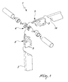
- the reference numeral 1 generally designates an apparatus for mutually stably connecting profiled elements 2.
- the apparatus 1 comprises inserts 3, which are suitable for stably accommodating, each within a respective profiled element 2, anchoring units 4 for anchoring to contoured ends 5 of the inserts 3 (each contoured end 5 is directed toward the outside of the respective profiled element 2), and a tension member 6 whose ends are associated with the units 4.
- each insert 3 comprises at least one plate-like body 7, whose width is complementary to the width of the accommodation internal cavity of the profiled element 2 that will accommodate it.
- an end 8 adapted to be directed outward is substantially inclined with respect to the longitudinal direction of the body 7 and is provided with appropriate contoured portions 5 (also referenced as contoured ends 5).
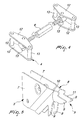
- the insert has a deviation with respect to the plane on which it lies, so that the end 8 lies on a second plane which is parallel to the preceding one.
- the inserts 3 are in fact two for each profiled element 2, are superimposed, and each has a surface in contact with a respective internal surface of the profiled element 2: the deviation with respect to the plane therefore entails a mutual approach of the two ends 8, which therefore do not interfere with said profiled element, facilitating the assembly operations.
- a layer of adhesive material is interposed between the internal surface of the profiled element 2 and the surface that rests thereon of each insert 3: since metallic parts are generally involved, it is convenient to use specific bonding agents, and possible applications using different materials, such as, purely by way of example, wood, polymeric and/or composite materials, are not excluded.
- suitable plates are arranged between the facing surfaces of the inserts 3, whose opposite faces rest against respective internal surfaces of the respective profiled element 2, and are at least as thick as the free height in the cavity of the profiled element 2 in order to force the inserts 3 against the contact surfaces.
- the layer of adhesive material is only an "additional safety", since the connection is ensured by the interlocking and friction coupling of the inserts forced against the internal surfaces of the profiled element 2.
- the plates can also comprise a fixed base and a movable head which can be actuated by way of a screw (or equivalent element) so that they are inserted between the inserts and then forced to open by way of said screw, increasing their thickness.
- the contoured ends 5 comprise two protruding lugs 9, which are separated by a concavity 10 which has a substantially circular shape; the surfaces 11 of the lugs 9 that lie opposite the ones formed by the concavity 10 are substantially inclined and converge in an overall V-shaped configuration.
- the lugs 9 diverge and their width is variable, since they are delimited by substantially linear portions on the outside (surfaces 11) and by a substantially circular portion on the inside (concavities 10).
- Each anchoring unit 4 comprises two plates 12 which face each other in a parallel configuration and between which perpendicular stems 13 are interposed which are firmly engaged on both of the respective plates 12.
- the plates 12 are substantially triangular and the stems 13 are three, engaged proximate to the vertices of the plates 12.
- the tension member 6 comprises respective end engagement elements, each adapted to mate with a respective stem 13 of a respective anchoring unit 4.
- the other stems 13 (the two stems of each unit 4 which are not engaged with the element of the tension member 6) rest against the lugs 9 of the contoured surfaces 5 of the inserts 3.
- the tension member 6 comprises a clamping means which is interposed between the engagement elements and whose movement entails the mutual approach and spacing of the engagement elements (with consequent mutual approach and spacing of the units 4 which are connected thereto and therefore also of the mutually coupled inserts 3).
- the profiled elements 2 are provided with a substantially circular end recess 14, which faces and is aligned with the concavities 10 of the contoured surfaces 5: the facing arrangement and alignment refer to the configuration in which the profiled elements 2 are coupled with their end edges in mutual contact.
- the recess 14 is designed to allow the access of the tool intended to move the clamping means for adjusting the tension member 6.
- the apparatus 1 therefore provides for the preliminary fitting of the inserts 3 within the respective profiled elements 2, which must be coupled at an angle of incidence for which they are already contoured appropriately (or the fitter will have to provide the inclined cuts at the ends of the profiled elements 2 and provide the recess 14). Assembly can occur by using only adhesive material or, more appropriately, the plates described earlier, which can be fixed or expansible.
- each one has a stem 13 which rests against the surface 11 of a lug 9 of an insert which is rigidly coupled to the first profiled element 2, a stem which rests on the same surface 11 related to the other profiled element 2, and the third stem 13 which faces the recess 14 (and the concavities 10).
- the tension member 6 is arranged between the "third" stems 13, and its actuation entails the mutual approach of the units 4, which by acting on the inclined surfaces 11 also entails the mutual approach of the profiled elements 2 (rigidly coupled to the respective inserts 3) until the converging surfaces are perfectly mated.
Landscapes
- Engineering & Computer Science (AREA)
- Civil Engineering (AREA)
- Structural Engineering (AREA)
- Joining Of Building Structures In Genera (AREA)
- Mutual Connection Of Rods And Tubes (AREA)
Applications Claiming Priority (1)
| Application Number | Priority Date | Filing Date | Title |
|---|---|---|---|
| IT000657A ITBO20060657A1 (it) | 2006-09-26 | 2006-09-26 | Apparato di collegamento reciproco stabile per profilati. |
Publications (2)
| Publication Number | Publication Date |
|---|---|
| EP1905937A2 true EP1905937A2 (de) | 2008-04-02 |
| EP1905937A3 EP1905937A3 (de) | 2009-04-15 |
Family
ID=38904756
Family Applications (1)
| Application Number | Title | Priority Date | Filing Date |
|---|---|---|---|
| EP07110139A Withdrawn EP1905937A3 (de) | 2006-09-26 | 2007-06-13 | Vorrichtung zum stabil miteinander Verbinden von profilierten Elementen |
Country Status (3)
| Country | Link |
|---|---|
| US (1) | US7611302B2 (de) |
| EP (1) | EP1905937A3 (de) |
| IT (1) | ITBO20060657A1 (de) |
Families Citing this family (5)
| Publication number | Priority date | Publication date | Assignee | Title |
|---|---|---|---|---|
| US9879472B2 (en) * | 2015-06-05 | 2018-01-30 | Quanex Corporation | Frame assembly including a cornerlock |
| US9869122B2 (en) | 2016-01-29 | 2018-01-16 | Quanex Corporation | Cornerlock having a self configurable first body member |
| CA2961099C (en) * | 2016-03-16 | 2021-04-27 | Quanex Homeshield, Llc | Cornerlock for a frame assembly including a collar |
| CN106869712B (zh) * | 2017-03-30 | 2018-10-23 | 浙江瑞明节能科技股份有限公司 | 一种铝木复合门窗的框扇组框结构 |
| US11162296B2 (en) * | 2019-11-22 | 2021-11-02 | Alpina Manufacturing Llc | Window having hinged corner arrangement |
Citations (1)
| Publication number | Priority date | Publication date | Assignee | Title |
|---|---|---|---|---|
| WO2004003326A1 (en) | 2002-06-26 | 2004-01-08 | Alfredo Pegoraro | A manufacturing process for wooden base window and door frames, and the frames manufactured by means of the process |
Family Cites Families (2)
| Publication number | Priority date | Publication date | Assignee | Title |
|---|---|---|---|---|
| US1878055A (en) * | 1925-11-14 | 1932-09-20 | Theodore H Wittliff | Stamped metal article and method of making same |
| IT1100312B (it) * | 1978-10-06 | 1985-09-28 | Mascioletti Ascanio | Squadretto atto a consentire il montaggio ad angolo di due profilati in genere,sia a superficie interna liscia,sia con alette riportate,per la produzione di serramenti,telai e simili |
-
2006
- 2006-09-26 IT IT000657A patent/ITBO20060657A1/it unknown
-
2007
- 2007-06-13 EP EP07110139A patent/EP1905937A3/de not_active Withdrawn
- 2007-06-14 US US11/808,949 patent/US7611302B2/en not_active Expired - Fee Related
Patent Citations (1)
| Publication number | Priority date | Publication date | Assignee | Title |
|---|---|---|---|---|
| WO2004003326A1 (en) | 2002-06-26 | 2004-01-08 | Alfredo Pegoraro | A manufacturing process for wooden base window and door frames, and the frames manufactured by means of the process |
Also Published As
| Publication number | Publication date |
|---|---|
| US20080072517A1 (en) | 2008-03-27 |
| EP1905937A3 (de) | 2009-04-15 |
| US7611302B2 (en) | 2009-11-03 |
| ITBO20060657A1 (it) | 2008-03-27 |
Similar Documents
| Publication | Publication Date | Title |
|---|---|---|
| KR101932560B1 (ko) | 기계적으로 연동하는 프레임 조립체 | |
| JP7252910B2 (ja) | マウント | |
| US7540540B2 (en) | Pipe coupling | |
| EP1905937A2 (de) | Vorrichtung zum stabil miteinander Verbinden von profilierten Elementen | |
| KR940019023A (ko) | 접지 콘넥터 | |
| EP3359824B1 (de) | Dreiseitige eckanordnung | |
| US8747016B2 (en) | Profile bar connection system | |
| US6955344B2 (en) | Tool and connector system for clamping | |
| KR20110046903A (ko) | 결속용 클램프 | |
| KR101592905B1 (ko) | 공동주택용 석재 고정장치 | |
| JP2010077692A (ja) | 折板屋根用取付具 | |
| US9352452B2 (en) | Panel support clamp | |
| US6305873B1 (en) | Jointing construction | |
| JP7335607B2 (ja) | パイプ取り付け用クランプ | |
| AU2015331586B2 (en) | Fastener for a connector in an electrical coupling | |
| CA2870792A1 (en) | Cutting tool assembly with removable tool head | |
| EP4148198A1 (de) | Verbinder für bauprofielen | |
| KR101814628B1 (ko) | 풀림방지용 탄성변형너트, 그 가공방법, 그 조립방법 및 변형소켓 | |
| JP2009035875A (ja) | 鉄筋とセパレータの接合金具 | |
| TWM380192U (en) | Clamping structure for vise | |
| JP2011026816A (ja) | パイプ連結クランプ | |
| JP2009074674A (ja) | 締結用部材 | |
| KR200365288Y1 (ko) | 프로파일 다각 연결구 | |
| EP3741262B1 (de) | Bettwinkel und zusammenbauverfahren eines bettrahmens | |
| JP4141900B2 (ja) | 複合ナット及び複合ナットを用いた支持板の支持方法 |
Legal Events
| Date | Code | Title | Description |
|---|---|---|---|
| PUAI | Public reference made under article 153(3) epc to a published international application that has entered the european phase |
Free format text: ORIGINAL CODE: 0009012 |
|
| AK | Designated contracting states |
Kind code of ref document: A2 Designated state(s): AT BE BG CH CY CZ DE DK EE ES FI FR GB GR HU IE IS IT LI LT LU LV MC MT NL PL PT RO SE SI SK TR |
|
| AX | Request for extension of the european patent |
Extension state: AL BA HR MK YU |
|
| PUAL | Search report despatched |
Free format text: ORIGINAL CODE: 0009013 |
|
| AK | Designated contracting states |
Kind code of ref document: A3 Designated state(s): AT BE BG CH CY CZ DE DK EE ES FI FR GB GR HU IE IS IT LI LT LU LV MC MT NL PL PT RO SE SI SK TR |
|
| AX | Request for extension of the european patent |
Extension state: AL BA HR MK RS |
|
| RAP1 | Party data changed (applicant data changed or rights of an application transferred) |
Owner name: CORRADI S.P.A. |
|
| 17P | Request for examination filed |
Effective date: 20091015 |
|
| AKX | Designation fees paid |
Designated state(s): AT BE BG CH CY CZ DE DK EE ES FI FR GB GR HU IE IS IT LI LT LU LV MC MT NL PL PT RO SE SI SK TR |
|
| STAA | Information on the status of an ep patent application or granted ep patent |
Free format text: STATUS: THE APPLICATION IS DEEMED TO BE WITHDRAWN |
|
| 18D | Application deemed to be withdrawn |
Effective date: 20140103 |