EP1905863A2 - Slide member - Google Patents
Slide member Download PDFInfo
- Publication number
- EP1905863A2 EP1905863A2 EP07017911A EP07017911A EP1905863A2 EP 1905863 A2 EP1905863 A2 EP 1905863A2 EP 07017911 A EP07017911 A EP 07017911A EP 07017911 A EP07017911 A EP 07017911A EP 1905863 A2 EP1905863 A2 EP 1905863A2
- Authority
- EP
- European Patent Office
- Prior art keywords
- coating layer
- layer
- slide member
- hard carbon
- carbon coating
- Prior art date
- Legal status (The legal status is an assumption and is not a legal conclusion. Google has not performed a legal analysis and makes no representation as to the accuracy of the status listed.)
- Withdrawn
Links
- 239000011247 coating layer Substances 0.000 claims abstract description 159
- 239000010410 layer Substances 0.000 claims abstract description 72
- 239000011651 chromium Substances 0.000 claims abstract description 54
- 239000000758 substrate Substances 0.000 claims abstract description 54
- 229910021385 hard carbon Inorganic materials 0.000 claims abstract description 49
- 229910052799 carbon Inorganic materials 0.000 claims abstract description 39
- 229910052804 chromium Inorganic materials 0.000 claims abstract description 29
- OKTJSMMVPCPJKN-UHFFFAOYSA-N Carbon Chemical compound [C] OKTJSMMVPCPJKN-UHFFFAOYSA-N 0.000 claims abstract description 28
- VYZAMTAEIAYCRO-UHFFFAOYSA-N Chromium Chemical compound [Cr] VYZAMTAEIAYCRO-UHFFFAOYSA-N 0.000 claims abstract description 12
- 229910052782 aluminium Inorganic materials 0.000 claims abstract description 12
- XAGFODPZIPBFFR-UHFFFAOYSA-N aluminium Chemical compound [Al] XAGFODPZIPBFFR-UHFFFAOYSA-N 0.000 claims abstract description 10
- 229910052742 iron Inorganic materials 0.000 claims abstract description 8
- 230000003247 decreasing effect Effects 0.000 claims abstract description 7
- 229910052750 molybdenum Inorganic materials 0.000 claims abstract description 7
- 229910052759 nickel Inorganic materials 0.000 claims abstract description 7
- 229910052741 iridium Inorganic materials 0.000 claims abstract description 6
- 229910052758 niobium Inorganic materials 0.000 claims abstract description 6
- 229910052697 platinum Inorganic materials 0.000 claims abstract description 6
- 229910052715 tantalum Inorganic materials 0.000 claims abstract description 6
- 229910052721 tungsten Inorganic materials 0.000 claims abstract description 6
- 229910052720 vanadium Inorganic materials 0.000 claims abstract description 6
- 229910052726 zirconium Inorganic materials 0.000 claims abstract description 6
- 238000000034 method Methods 0.000 claims description 20
- 239000002344 surface layer Substances 0.000 claims description 19
- 230000003746 surface roughness Effects 0.000 claims description 9
- 238000007733 ion plating Methods 0.000 claims description 6
- 238000004544 sputter deposition Methods 0.000 claims description 6
- 239000000463 material Substances 0.000 claims description 5
- 229910052710 silicon Inorganic materials 0.000 claims description 4
- 239000010703 silicon Substances 0.000 claims description 3
- UFGZSIPAQKLCGR-UHFFFAOYSA-N chromium carbide Chemical compound [Cr]#C[Cr]C#[Cr] UFGZSIPAQKLCGR-UHFFFAOYSA-N 0.000 claims description 2
- 238000004519 manufacturing process Methods 0.000 claims description 2
- 229910003470 tongbaite Inorganic materials 0.000 claims description 2
- JXOOCQBAIRXOGG-UHFFFAOYSA-N [B].[B].[B].[B].[B].[B].[B].[B].[B].[B].[B].[B].[Al] Chemical compound [B].[B].[B].[B].[B].[B].[B].[B].[B].[B].[B].[B].[Al] JXOOCQBAIRXOGG-UHFFFAOYSA-N 0.000 claims 1
- CAVCGVPGBKGDTG-UHFFFAOYSA-N alumanylidynemethyl(alumanylidynemethylalumanylidenemethylidene)alumane Chemical compound [Al]#C[Al]=C=[Al]C#[Al] CAVCGVPGBKGDTG-UHFFFAOYSA-N 0.000 claims 1
- WNROFYMDJYEPJX-UHFFFAOYSA-K aluminium hydroxide Chemical compound [OH-].[OH-].[OH-].[Al+3] WNROFYMDJYEPJX-UHFFFAOYSA-K 0.000 claims 1
- PMHQVHHXPFUNSP-UHFFFAOYSA-M copper(1+);methylsulfanylmethane;bromide Chemical compound Br[Cu].CSC PMHQVHHXPFUNSP-UHFFFAOYSA-M 0.000 claims 1
- TWNQGVIAIRXVLR-UHFFFAOYSA-N oxo(oxoalumanyloxy)alumane Chemical compound O=[Al]O[Al]=O TWNQGVIAIRXVLR-UHFFFAOYSA-N 0.000 claims 1
- 238000012360 testing method Methods 0.000 description 49
- 230000000052 comparative effect Effects 0.000 description 23
- 239000003921 oil Substances 0.000 description 22
- 238000005299 abrasion Methods 0.000 description 19
- 238000005259 measurement Methods 0.000 description 17
- 229910003460 diamond Inorganic materials 0.000 description 15
- 239000010432 diamond Substances 0.000 description 15
- 229910052751 metal Inorganic materials 0.000 description 14
- 239000002184 metal Substances 0.000 description 14
- 238000000576 coating method Methods 0.000 description 13
- 238000011156 evaluation Methods 0.000 description 12
- 239000004215 Carbon black (E152) Substances 0.000 description 9
- 239000011248 coating agent Substances 0.000 description 9
- 239000007789 gas Substances 0.000 description 9
- 229930195733 hydrocarbon Natural products 0.000 description 9
- 150000002430 hydrocarbons Chemical class 0.000 description 8
- 239000010687 lubricating oil Substances 0.000 description 8
- 229910000831 Steel Inorganic materials 0.000 description 7
- XLYOFNOQVPJJNP-UHFFFAOYSA-M hydroxide Chemical compound [OH-] XLYOFNOQVPJJNP-UHFFFAOYSA-M 0.000 description 7
- 238000007373 indentation Methods 0.000 description 7
- XEEYBQQBJWHFJM-UHFFFAOYSA-N iron Substances [Fe] XEEYBQQBJWHFJM-UHFFFAOYSA-N 0.000 description 7
- PXHVJJICTQNCMI-UHFFFAOYSA-N nickel Substances [Ni] PXHVJJICTQNCMI-UHFFFAOYSA-N 0.000 description 7
- 239000010959 steel Substances 0.000 description 7
- XLYOFNOQVPJJNP-UHFFFAOYSA-N water Substances O XLYOFNOQVPJJNP-UHFFFAOYSA-N 0.000 description 7
- 230000001603 reducing effect Effects 0.000 description 6
- BASFCYQUMIYNBI-UHFFFAOYSA-N platinum Substances [Pt] BASFCYQUMIYNBI-UHFFFAOYSA-N 0.000 description 5
- 230000015572 biosynthetic process Effects 0.000 description 4
- 239000010955 niobium Substances 0.000 description 4
- 229910003481 amorphous carbon Inorganic materials 0.000 description 3
- 238000005336 cracking Methods 0.000 description 3
- 239000000446 fuel Substances 0.000 description 3
- 150000001247 metal acetylides Chemical class 0.000 description 3
- 239000003960 organic solvent Substances 0.000 description 3
- 238000005268 plasma chemical vapour deposition Methods 0.000 description 3
- 238000004088 simulation Methods 0.000 description 3
- 238000004833 X-ray photoelectron spectroscopy Methods 0.000 description 2
- VNTLIPZTSJSULJ-UHFFFAOYSA-N chromium molybdenum Chemical compound [Cr].[Mo] VNTLIPZTSJSULJ-UHFFFAOYSA-N 0.000 description 2
- 238000002485 combustion reaction Methods 0.000 description 2
- 230000007613 environmental effect Effects 0.000 description 2
- 229910002804 graphite Inorganic materials 0.000 description 2
- 239000010439 graphite Substances 0.000 description 2
- 125000002887 hydroxy group Chemical group [H]O* 0.000 description 2
- 239000007788 liquid Substances 0.000 description 2
- 235000019602 lubricity Nutrition 0.000 description 2
- FXNGWBDIVIGISM-UHFFFAOYSA-N methylidynechromium Chemical group [Cr]#[C] FXNGWBDIVIGISM-UHFFFAOYSA-N 0.000 description 2
- 239000000203 mixture Substances 0.000 description 2
- 238000012986 modification Methods 0.000 description 2
- 230000004048 modification Effects 0.000 description 2
- 150000004767 nitrides Chemical class 0.000 description 2
- 230000009467 reduction Effects 0.000 description 2
- 239000007787 solid Substances 0.000 description 2
- 238000004381 surface treatment Methods 0.000 description 2
- ZOKXTWBITQBERF-UHFFFAOYSA-N Molybdenum Chemical compound [Mo] ZOKXTWBITQBERF-UHFFFAOYSA-N 0.000 description 1
- 229910018104 Ni-P Inorganic materials 0.000 description 1
- 229910018536 Ni—P Inorganic materials 0.000 description 1
- ATJFFYVFTNAWJD-UHFFFAOYSA-N Tin Chemical compound [Sn] ATJFFYVFTNAWJD-UHFFFAOYSA-N 0.000 description 1
- QCWXUUIWCKQGHC-UHFFFAOYSA-N Zirconium Chemical compound [Zr] QCWXUUIWCKQGHC-UHFFFAOYSA-N 0.000 description 1
- 239000000654 additive Substances 0.000 description 1
- 150000001298 alcohols Chemical class 0.000 description 1
- 239000000956 alloy Substances 0.000 description 1
- 229910045601 alloy Inorganic materials 0.000 description 1
- QVGXLLKOCUKJST-UHFFFAOYSA-N atomic oxygen Chemical compound [O] QVGXLLKOCUKJST-UHFFFAOYSA-N 0.000 description 1
- 150000001721 carbon Chemical class 0.000 description 1
- 239000011203 carbon fibre reinforced carbon Substances 0.000 description 1
- 230000008859 change Effects 0.000 description 1
- 238000005229 chemical vapour deposition Methods 0.000 description 1
- 239000010941 cobalt Substances 0.000 description 1
- 229910017052 cobalt Inorganic materials 0.000 description 1
- GUTLYIVDDKVIGB-UHFFFAOYSA-N cobalt atom Chemical compound [Co] GUTLYIVDDKVIGB-UHFFFAOYSA-N 0.000 description 1
- 150000001875 compounds Chemical class 0.000 description 1
- 238000010276 construction Methods 0.000 description 1
- 238000005520 cutting process Methods 0.000 description 1
- 230000007423 decrease Effects 0.000 description 1
- 238000000151 deposition Methods 0.000 description 1
- 238000010891 electric arc Methods 0.000 description 1
- 238000005265 energy consumption Methods 0.000 description 1
- 238000000227 grinding Methods 0.000 description 1
- -1 hydrocarbon ions Chemical class 0.000 description 1
- 230000005660 hydrophilic surface Effects 0.000 description 1
- 238000007737 ion beam deposition Methods 0.000 description 1
- 150000002500 ions Chemical class 0.000 description 1
- GKOZUEZYRPOHIO-UHFFFAOYSA-N iridium atom Chemical compound [Ir] GKOZUEZYRPOHIO-UHFFFAOYSA-N 0.000 description 1
- 238000001755 magnetron sputter deposition Methods 0.000 description 1
- 230000008018 melting Effects 0.000 description 1
- 238000002844 melting Methods 0.000 description 1
- 239000007769 metal material Substances 0.000 description 1
- 239000011733 molybdenum Substances 0.000 description 1
- 239000010705 motor oil Substances 0.000 description 1
- GUCVJGMIXFAOAE-UHFFFAOYSA-N niobium atom Chemical compound [Nb] GUCVJGMIXFAOAE-UHFFFAOYSA-N 0.000 description 1
- 238000000399 optical microscopy Methods 0.000 description 1
- 229910052760 oxygen Inorganic materials 0.000 description 1
- 239000001301 oxygen Substances 0.000 description 1
- 239000004033 plastic Substances 0.000 description 1
- 238000007747 plating Methods 0.000 description 1
- 239000003507 refrigerant Substances 0.000 description 1
- 238000009877 rendering Methods 0.000 description 1
- 238000003786 synthesis reaction Methods 0.000 description 1
- GUVRBAGPIYLISA-UHFFFAOYSA-N tantalum atom Chemical compound [Ta] GUVRBAGPIYLISA-UHFFFAOYSA-N 0.000 description 1
- 230000009466 transformation Effects 0.000 description 1
- JLTRXTDYQLMHGR-UHFFFAOYSA-N trimethylaluminium Chemical compound C[Al](C)C JLTRXTDYQLMHGR-UHFFFAOYSA-N 0.000 description 1
- WFKWXMTUELFFGS-UHFFFAOYSA-N tungsten Chemical compound [W] WFKWXMTUELFFGS-UHFFFAOYSA-N 0.000 description 1
- 239000010937 tungsten Substances 0.000 description 1
- GPPXJZIENCGNKB-UHFFFAOYSA-N vanadium Chemical compound [V]#[V] GPPXJZIENCGNKB-UHFFFAOYSA-N 0.000 description 1
- 239000012808 vapor phase Substances 0.000 description 1
Images


Classifications
-
- C—CHEMISTRY; METALLURGY
- C23—COATING METALLIC MATERIAL; COATING MATERIAL WITH METALLIC MATERIAL; CHEMICAL SURFACE TREATMENT; DIFFUSION TREATMENT OF METALLIC MATERIAL; COATING BY VACUUM EVAPORATION, BY SPUTTERING, BY ION IMPLANTATION OR BY CHEMICAL VAPOUR DEPOSITION, IN GENERAL; INHIBITING CORROSION OF METALLIC MATERIAL OR INCRUSTATION IN GENERAL
- C23C—COATING METALLIC MATERIAL; COATING MATERIAL WITH METALLIC MATERIAL; SURFACE TREATMENT OF METALLIC MATERIAL BY DIFFUSION INTO THE SURFACE, BY CHEMICAL CONVERSION OR SUBSTITUTION; COATING BY VACUUM EVAPORATION, BY SPUTTERING, BY ION IMPLANTATION OR BY CHEMICAL VAPOUR DEPOSITION, IN GENERAL
- C23C14/00—Coating by vacuum evaporation, by sputtering or by ion implantation of the coating forming material
- C23C14/02—Pretreatment of the material to be coated
- C23C14/027—Graded interfaces
-
- C—CHEMISTRY; METALLURGY
- C23—COATING METALLIC MATERIAL; COATING MATERIAL WITH METALLIC MATERIAL; CHEMICAL SURFACE TREATMENT; DIFFUSION TREATMENT OF METALLIC MATERIAL; COATING BY VACUUM EVAPORATION, BY SPUTTERING, BY ION IMPLANTATION OR BY CHEMICAL VAPOUR DEPOSITION, IN GENERAL; INHIBITING CORROSION OF METALLIC MATERIAL OR INCRUSTATION IN GENERAL
- C23C—COATING METALLIC MATERIAL; COATING MATERIAL WITH METALLIC MATERIAL; SURFACE TREATMENT OF METALLIC MATERIAL BY DIFFUSION INTO THE SURFACE, BY CHEMICAL CONVERSION OR SUBSTITUTION; COATING BY VACUUM EVAPORATION, BY SPUTTERING, BY ION IMPLANTATION OR BY CHEMICAL VAPOUR DEPOSITION, IN GENERAL
- C23C14/00—Coating by vacuum evaporation, by sputtering or by ion implantation of the coating forming material
- C23C14/06—Coating by vacuum evaporation, by sputtering or by ion implantation of the coating forming material characterised by the coating material
- C23C14/0605—Carbon
Definitions
- the present invention relates to slide members comprising a hard carbon coating with a low friction.
- Hard carbon coatings generally have features of a high hardness, a smooth surface, excellent friction resistance, and a low coefficient of friction; and these excellent friction properties are attributed to their solid lubricity. Under unlubricated condition, the surface friction coefficient is 0.5 to 1.0 for the smooth surface of typical steel and approximately 0.4 for conventional surface treatment materials such as Ni-P or Cr plating, and TiN or CrN coating; while hard carbon coatings have a surface friction coefficient of approximately 0.12.
- a slide member comprising a diamond-like carbon layer as a hard carbon coating is described in JP-A-2004-010923 and JP-A-2000-256850 .
- Such conventional slide members comprising a diamond-like carbon layer have a problem in that they do not always provide a low coefficient of friction under the unlubricated condition.
- a slide member comprising a hard carbon coating layer with excellent abrasion resistance and low friction properties.
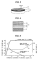
- FIG. 1 is a schematic illustration showing a perspective view of a test specimen with a hard carbon coating layer formed thereon.
- a hard carbon coating layer 13 was evaluated for the adhesiveness, hardness and Young's modulus using a test specimen 11, which comprises the hard carbon coating layer 13 formed on a disc substrate 12 having a diameter of 21.5 mm and a thickness of 5.2 mm as shown in Fig. 1.
- the test specimens 11 were prepared by forming the hard carbon coating 13 on the substrate 12 using the conditions (Al content, applied bias voltage, and conformation of the gradient layer) shown in Table 1.
- Example 1 1.88 100 Linear None 27.82 158.7 0.046 588 47% None Comparative example 1 0 100 Stepwise Observed - - - - - - Comparative example 2 0 100 Linear None 30.23 178.70 0.090 981 43% Partial Peeling and Roughness Comparative example 3 0.65 50 Linear None 9.378 65.94
- the hard carbon coating layer 13 was formed by depositing a diamond-like carbon (DLC) layer on the substrate 12 using an unbalanced magnetron sputtering (UBMS) method.
- the UBMS method is a film forming method having the following features. Magnetic poles disposed behind a target are intentionally unbalanced in magnetic strength between at the center and periphery of the target to produce a nonequilibrium state, thereby causing a part of the magnetic line of force from the magnetic pole at the periphery of the target to extend to a substrate. This, in return, helps plasma conventionally concentrated in the vicinity of the target to diffuse along the extended magnetic line of force. Therefore, the substrate 12 can be irradiated with an increased amount of ions during the formation of the hard carbon coating layer 13, thereby enabling the denser coating layer 13 to be formed on the substrate 12.
- the hard carbon coating layer (henceforth referred to as "coating layer") 13 it was evaluated for the adhesiveness by examining for peeling of the coating layer 13 in an indentation test using a Rockwell diamond indenter.
- the surface of the coating layer 13 was also evaluated by a nano indentation method (ISO14577), and was measured for the peel load by a friction test under an unlubricated condition.
- the coating layer formed on a crown surface of a cam lifter for automotive engines was measured for the friction torque under an oil lubricated condition to calculate reduction rate of the torque, and the coating layer 13 was also examined for peeling after a durability test under the oil lubricated condition.
- Fig. 2 is a schematic illustration showing a sectional view of an abrasion tester 21 used for evaluation in an embodiment of the present invention
- Fig. 3 is a schematic illustration showing a perspective view of a sliding portion between a test specimen 11 and a ball 24 of the abrasion tester used for the evaluation.
- the friction test under an unlubricated condition was performed using an evaluation device (an abrasion tester 21) as shown in Fig. 2.
- the coating layers 13 were measured for the coefficient of friction and the peel load with this abrasion tester (ball-on-disk type abrasion tester) 21.
- the tester 21 is provided with a work table 23 fixed to a rotating shaft 22. On the work table 23 is loaded the test specimen 11, on the upper side of which is placed a 6mm-diameter metal ball (high carbon chromium bearing steel ball) 24 as the counterpart of the test specimen 11.
- a metal material used for the metal ball 24 is not limited to the high carbon chromium bearing steel, but may be any steel used for bearings.
- the tester 21 is so configured that a spring 25 is used to increase the applied load stepwise by 98 N every one minute from 98 to 2452 N.
- the metal ball 24 is fixed to a holder 26 to prevent the rotation of the ball.
- the rotating shaft 22 driven by a motor 27 was rotated at a sliding velocity of approximately 34 mm/sec relative to the metal ball 24, and the torque corresponding to the friction force generated between the metal ball 24 and test specimen 11 was measured by a load cell 28 to calculate the coefficient of friction.
- one metal ball 24 is disposed 8 mm from the rotation center and a load of P is applied to it as shown in Fig. 3.
- the peel load value of the coating layer 13 was defined as a test load value at which the coefficient of friction between the test specimen 11 and the metal ball 24 abruptly increased. Furthermore, this friction test was performed under an unlubricated condition at room temperature and normal humidity (room temperature: approximately 25°C, humidity: approximately 60% RH).
- Fig. 13 is a schematic illustration of a simulation test device of a motor vehicle cam lifter.
- the friction torque measurement in the durability test under an oil lubricated condition was performed using a simulation test device 51 as shown in Fig. 13.
- the test conditions were as follows: a cam 54 was rotated at 300 rpm while an engine oil 55 (SAE 5W-30, 80°C) was dropped thereon, and the torque applied to the cam shaft was measured after 2 hours from the start of the test. After this test, the coating layer formed on a crown surface 53 of a motor vehicle cam lifter 52 was examined for peeling by a surface shape measurement.
- the disk substrate 12 of an alloy (chromium molybdenum steel) containing Fe, Cr and Mo was carburized to have a Rockwell C scale surface hardness (HRC) of 58 or more, and was dressed to have an average surface roughness (Ra) of 0.1 ⁇ m or less. Then, a coating layer 13 was formed by an UBMS method while introducing inert and hydrocarbon gases so as to have an Al content of 1.88 at.%.
- Fig. 4 is a schematic illustration showing a partial cross sectional view of a test specimen 11 comprising the coating layer 13 formed on the substrate 12.
- the coating layer 13 has a Cr intermediate layer 41, an outermost surface layer 43 and a gradient layer 42 disposed between the intermediate layer 41 and the outermost surface layer 43.
- the powers input to the Cr and C targets and bias voltage applied to the substrate were controlled as shown in Fig. 5.
- Fig. 5 is a graph indicating a method for controlling with time powers input to Cr and C targets and a bias voltage applied to a substrate when forming a gradient layer of Example 1 and Comparative example 2.
- the formed coating layer 13 was evaluated for the adhesiveness by forcing the Rockwell diamond indenter into the coating layer at a load of 1471 N.
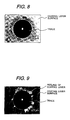
- the result showed excellent adhesiveness between the substrate 12 and the coating layer 13 because no peeling was observed around the trace as shown in Fig. 8.
- Fig. 8 is a photograph of a plan view of a trace forced into the coating layer 13, which exhibits no peeling in an adhesiveness evaluation using a Rockwell diamond indenter.
- the coating layer 13 had a hardness of 27.82 GPa and a Young's modulus of 158.7 GPa.
- the coefficient of friction and peel load of the coating layer 13 were determined to be 0.046 and 588 N respectively from the result of the friction test between the coating layer 13 and a metal ball 24 under an unlubricated condition.
- the coating layer 13 of Example 1 is not subject to any peeling from the substrate 12 so that the substrate 12 is never exposed, thus enabling efficient use of the low friction properties of the coating layer 13.
- the coefficient of friction was 0.1 or less, meaning that the coefficient of friction could be reduced by approximately 88 to 96% compared to steel without the coating layer 13 or with conventional surface treatments, and could be reduced by approximately 62% compared to conventional coating layers.
- the peel load of the coating layer 13 is as large as 490 N or more, thereby enabling efficient use of the low friction properties of the coating layer 13 even under higher load condition than usual.
- the coating layer 13 was applied to a crown surface 53 (carburized to have an HRC value not less than 58 and dressed to have an Ra value not more than 0.1 ⁇ m) of a motor vehicle cam lifter 52 as shown in Fig. 13 by an UBMS method while introducing inert and hydrocarbon gases similarly to the case of the substrate 12.
- the result of the friction torque measurement in durability test under an oil lubricated condition was that in the case of Example 1, the torque could be reduced by approximately 47% compared to a typical torque for motor vehicle cam lifters without the coating layer 13.
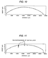
- the coating layer 13 formed on the crown surface 53 exhibited no peeling as can be seen from Fig. 10.
- Fig. 10 is a result of a surface shape measurement on the coating layer 13 applied to the crown surface 53 of the motor vehicle cam lifter 52, in Example 1, after the friction torque measurement in the durability test under the oil lubricated condition.
- Applying the coating layer 13 of Example 1 to the motor vehicle cam lifter 52 reduces the torque applied thereto, thus reducing the slide load between the cam lifter 52 and a cam 54. Furthermore, there is produced no peeling of the coating layer 13, thus enabling continuous use of the low friction properties of the coating layer 13.
- This can provide a motive power engine (such as an automotive engine) capable of maintaining a high energy efficiency due to a low mechanical loss over a long period of time.
- the coating layer 13 of Example 1 is not subject to any peeling from the substrate 12 (the crown surface 53 of the cam lifter 52 for automotive engines) so that the substrate 12 is never exposed, thus enabling efficient use of the low friction properties of the coating layer 13.
- the coating layer 13 of Example 1 is a hard carbon coating layer containing both sp 2 bonded carbon typified by the carbon bond of graphite and sp 3 bonded carbon typified by the carbon bond of diamond. This can provide the coating layer 13 having both abrasion resistance and low friction properties.
- a hard carbon coating layer is made of amorphous carbon or hydrogenated carbon, and is called amorphous carbon, hydrogenated amorphous carbon (a-C:H), diamond-like carbon (DLC) or the like.
- the method for forming the hard carbon coating layer includes: plasma CVD (chemical vapor deposition) in which hydrocarbon gas is decomposed by plasma to form a film; vapor phase synthesis such as ion beam deposition using carbon or hydrocarbon ions; ion plating in which graphite or the like is vaporized by arc discharge to form a film; and sputtering in which a target is sputtered in an inert atmosphere to form a film.
- plasma CVD chemical vapor deposition
- vapor phase synthesis such as ion beam deposition using carbon or hydrocarbon ions
- ion plating in which graphite or the like is vaporized by arc discharge to form a film
- sputtering in which a target is sputtered in an inert atmosphere to form a film.
- the coating layer of Example 1 combines excellent adhesiveness, abrasion resistance and low friction properties, thereby rendering the coating applicable to slide members. Accordingly, this can provide a slide member capable of reducing load under an unlubricated condition as well as under water, organic solvent, fuel and oil lubricated conditions. In addition, a machine component normally sliding in a lubricating oil can maintain its reliability even when the lubricating oil runs short, thus reducing the amount of lubricating oil.
- the substrate 12 having the coating layer 13 formed thereon preferably contains at least one element selected from the group made up of V, Cr, Fe, Co, Ni, Zr, Nb, Mo, Ta, W, Ir and Pt. Furthermore, because the temperature rises during the formation of the coating layer 13, it more preferably contains a high melting point metal (in particular, Fe, Co and Ni) to prevent the transformation of the substrate.
- the Cr intermediate layer 41 is also formed before forming the hard carbon coating layer. Therefore, the substrate preferably contains Cr to improve adhesiveness between the substrate 12 and the Cr intermediate layer 41.
- the gradient layer 42 formed between the Cr intermediate layer 41 and outermost surface layer 43 preferably has a continuously decreasing Cr concentration and continuously increasing C concentration from the Cr intermediate layer 41 side to the outermost surface layer 43 side.
- each layer preferably has a thickness of 15 nm or less. If Cr carbide, one of the materials composing the gradient layer 42, is expressed as Cr x C y , its composition can be gradually varied from the Cr intermediate layer 41 side to the outermost surface layer 43 side by gradually varying the ratio of x and y. Therefore, it prevents abrupt change in film characteristic in the thickness direction of the gradient layer 42.
- the coating layer 13 When a thickness of the coating layer 13 is less than 0.15 ⁇ m, the layer is more prone to be worn away by sliding movement. While, a thickness of the coating 13 is more than 6.0 ⁇ m, the layer has a higher internal stress and is thereby more prone to peel off. Therefore, the coating layer 13 preferably has a thickness within a range of 0.15 to 6.0 ⁇ m. Since the coating layer 13 has a high surface hardness, the greater the average surface roughness is above 0.1 ⁇ m, the more likely it is to wear away the counterpart. Therefore, the coating layer 13 preferably has an average surface roughness of 0.1 ⁇ m or less. Additionally, when the thicknesses of the gradient layer 42 and the outermost surface layer 43 are denoted by d G and d C respectively, it is preferred that d C /d G s 1.
- the coating layer 13 is preferably formed by sputtering, plasma CVD, ion plating or the like, more preferably formed by sputtering or ion plating.
- the coating layer 13 contains Al in the outermost surface layer 43. Its content is preferably within a range of 0.5 to 4.5 at.%, more preferably within a range of 0.6 to 1.9 at.%.
- the Al is contained in the form of at least one material selected from the group made up of Al metal, Al boride, Al carbide, Al nitride, Al oxide and Al hydroxide, and preferably in the form of Al oxide and/or Al hydroxide.
- the test specimen 11 formed according to Example 1 combines excellent adhesiveness, abrasion resistance and low friction properties, and is thus applicable to slide members. Accordingly, this can provide a slide member capable of reducing load under an unlubricated condition as well as under water, organic solvent, fuel and oil lubricated conditions. Also, a machine component normally sliding in a lubricating oil can maintain its reliability even when the lubricating oil runs short, thus reducing the amount of lubricating oil.
- Al exposed on the surface of the coating layer 13 reacts with oxygen, water or the like in the atmosphere to form an Al oxide or Al hydroxide, thereby also providing a dielectric coating layer with stable electrical properties although it contains metal.
- Al contained in such a coating layer 13 is present on its surface in the form of Al oxide and/or Al hydroxide. That is, the coating layer 13 (in particular, the outermost surface layer 43) has a hydrophilic surface, thereby enabling realization of low friction properties in a water lubricated sliding movement. This also permits realization of low friction properties in a sliding movement under the presence of liquid or steam having the same OH-group as water (e.g., alcohols or additives in oil).
- Example 1 is actually based on the discovery of a phenomenon in which the presence of Al in the coating layer 13 reduces its internal stress, thereby causing it less likely to be peeled away from the substrate 12.
- the outermost surface layer contains less amount of Al oxide and/or Al hydroxide from which the hydrophilicity is derived, and thus cannot be expected to produce a friction reducing effect.
- XPS X-ray photoelectron spectroscopy
- a surface hardness of the coating layer 13 is more than 20 GPa.
- the surface hardness less than 20 GPa lowers the abrasion resistance, thus making the coating layer 13 more prone to abrasion.
- Addition of Al to the coating layer 13 tends to lower the hardness of the layer compared to the case without such addition.
- addition of Si (silicon) with Al to the layer is effective to increase the hardness.
- a surface Young's modulus of the coating layer 13 is within a range of 50 to 180 GPa. The Young's modulus is increased by the formation of Al carbides, but when it exceeds 180 GPa, the coating layer 13 is more prone to cracking or peeling. On the other hand, when the Young's modulus is less than 50 GPa, it lowers the load bearing properties in a sliding movement.
- the coating layer 13 has a high affinity to liquid or steam with OH-groups, thus enabling realization of low friction properties under a water lubricated condition.
- the coating layer 13 containing Al can be formed by using an Al target in the case of sputtering or ion plating.
- an organic Al compound typified by trimethylaluminum can be introduced as gas into the chamber to form the coating layer 13 containing Al.
- a high adhesiveness to the substrate 12 can be realized by using the hard carbon coating layer 13 in which the gradient layer 42 has a decreasing Cr concentration and increasing C concentration from the Cr intermediate layer 41 side to the outermost surface layer 43 side, and further the outermost surface layer 43 contains Al.
- Such a coating layer can be used not only under an unlubricated condition, but also under water, organic solvent, fuel and oil lubricated conditions.
- the gradient layer 42 preferably has a continuously decreasing Cr concentration and continuously increasing C concentration from the Cr intermediate layer 41 side to the outermost surface layer 43 side. Further, the gradient layer 42 preferably has a thickness within a range of 0.25 to 5.0 ⁇ m.
- the outermost surface of the coating 13 (the outermost surface layer 43) contains at least Al, or contains both Al and Si. Additionally, the coating layer 13 preferably has a total thickness within a range of 0.5 to 4 ⁇ m.
- a slide member according to a preferred embodiment of the present invention can be applied to applications that require durability, e.g., motor vehicle slide components (in particular, engine cylinders), and vanes for refrigerant compressors or rotary compressors used in refrigerators, air conditioners, etc.
- JIS SCM415 was carburized to have a surface hardness HRC not less than 58, and was dressed to have an average surface roughness Ra not more than 0.1 ⁇ m.
- JIS SCM415" is a kind of chromium molybdenum steels and contains 0.13-0.18 wt.% of C; 0.15-0.35 wt.% of Si; 0.60-0.90 wt.% of Mn; 0.90-1.20 wt.% of Cr; 0.15-0.25 wt.% of Mo; not more than 0.030 wt.% of P; not more than 0.030 wt.% of S; not more than 0.25 wt.% of Ni; and not more than 0.30 wt.% of Cu.
- a coating layer 13 was formed by an UBMS method while introducing inert and hydrocarbon gases. Al was not added to the coating layer 13 of Comparative example 1.
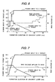
- the powers input to the Cr and C targets and the bias voltage applied to the substrate were controlled as shown in Fig. 6.
- Fig. 6 is a graph indicating a method for controlling with time powers input to the Cr and C targets and the bias voltage applied to the substrate 12 when forming the gradient layer 42 of Comparative example 1.
- Fig. 9 is a photograph of a plan view of a trace forced into the coating layer 13, which exhibits some amount of peeling in an adhesiveness evaluation using a Rockwell diamond indenter.
- the coating layer 13 of Comparative example 1 is subject to peeling from the substrate 12, which causes the substrate 12 to be exposed, thus preventing efficient use of the low friction properties of the coating layer 13. Further, when the coating layer 13 of Comparative example 1 is applied to a slide member in a mechanical device, the load to the mechanical device in which the slide member moves cannot be reduced, thus failing to provide any mechanical device with a high energy efficiency.
- a disk substrate 12 made of JIS SCM415 was carburized to have a surface hardness HRC not less than 58, and was finish processed to have an average surface roughness Ra not more than 0.1 ⁇ m. Then, a coating layer 13 was formed by an UBMS method while introducing inert and hydrocarbon gases. Al was not added to the coating layer 13 of Comparative example 2.
- the powers input to the Cr and C targets and the bias voltage applied to the substrate were controlled as shown in Fig. 5.
- the formed coating layer 13 was evaluated for the adhesiveness by forcing the Rockwell diamond indenter into the coating layer 13 at a load of 1471 N.
- the result showed an excellent adhesiveness between the substrate 12 and the coating layer 13 because no peeling was observed around the trace as shown in Fig. 8.
- the coating layer 13 had a hardness of 30.23 GPa and a Young's modulus of 178.7 GPa.
- the coefficient of friction and the peel load of the coating layer 13 were determined to be 0.090 and 981 N respectively from the result of the friction test between the coating layer 13 and a metal ball 24 under an unlubricated condition.
- a coating layer 13 was applied to a crown surface 53 (carburized to have an HRC value not less than 58 and finish processed to have an Ra value not more than 0.1 ⁇ m) of a motor vehicle cam lifter 52 made of JIS SCM415 by an UBMS method while introducing inert and hydrocarbon gases similarly to the case of the substrate 12.
- the result of the friction torque measurement in durability test under an oil lubricated condition was that in the case of Comparative example 2, the torque could be reduced by approximately 43% compared to a typical torque for motor vehicle cam lifters without the coating layer 13.
- Fig. 11 is a result of a surface shape measurement on the coating layer 13 applied to the crown surface 53 of the motor vehicle cam lifter 52, in Comparative example 2, after the friction torque measurement in the durability test under the oil lubricated condition.
- a disk substrate 12 made of JIS SCM415 was carburized to have a surface hardness HRC not less than 58, and was finish processed to have an average surface roughness Ra not more than 0.1 ⁇ m. Then, a coating layer 13 was formed by an UBMS method while introducing inert and hydrocarbon gases. The coating layer 13 of Comparative example 3 was formed to contain 0.65 at.% of Al.
- Fig. 7 is a graph indicating a method for controlling with time powers input to the Cr and C targets and the bias voltage applied to the substrate 12 when forming the gradient layer 43 of Comparative example 3.
- the formed coating layer 13 was evaluated for the adhesiveness by forcing the Rockwell diamond indenter into the coating layer 13 at a load of 1471 N.
- the result showed an excellent adhesiveness between the substrate 12 and the coating layer 13 because no peeling was observed around the trace as shown in Fig. 8.
- the coating layer 13 had a hardness of 9.378 GPa and a Young's modulus of 65.94 GPa.
- the coefficient of friction and the peel load of the coating layer 13 were determined to be 0.052 and 2452 N respectively from the results of the friction test between the coating layer 13 and a metal ball 24 under an unlubricated condition.
- a coating layer 13 was applied to a crown surface 53 (carburized to have an HRC value not less than 58 and finish processed to have an Ra value not more than 0.1 ⁇ m) of a motor vehicle cam lifter 52 made of JIS SCM415 by an UBMS method while introducing inert and hydrocarbon gases similarly to the case of the substrate 12.
- the result of the friction torque measurement in durability test for Comparative example 3 under an oil lubricated condition was that the torque could not be reduced but increased by approximately 3% compared to a typical torque for motor vehicle cam lifters without the coating layer 13.
- Fig. 12 is a result of a surface shape measurement on the coating layer 13 applied to the crown surface 53 of the motor vehicle cam lifter 52, in Comparative example 3, after the friction torque measurement in the durability test under an oil lubricated condition.
- the present invention is a slide member comprising a hard carbon coating layer with excellent abrasion resistance and low friction properties and can be applied to machine components such as internal combustion engines which are used under an oil lubricated condition.
Landscapes
- Chemical & Material Sciences (AREA)
- Chemical Kinetics & Catalysis (AREA)
- Engineering & Computer Science (AREA)
- Materials Engineering (AREA)
- Mechanical Engineering (AREA)
- Metallurgy (AREA)
- Organic Chemistry (AREA)
- Physical Vapour Deposition (AREA)
- Other Surface Treatments For Metallic Materials (AREA)
- Laminated Bodies (AREA)
- Electroplating Methods And Accessories (AREA)
- Lubricants (AREA)
Abstract
Description
- The present invention relates to slide members comprising a hard carbon coating with a low friction.
- Hard carbon coatings generally have features of a high hardness, a smooth surface, excellent friction resistance, and a low coefficient of friction; and these excellent friction properties are attributed to their solid lubricity. Under unlubricated condition, the surface friction coefficient is 0.5 to 1.0 for the smooth surface of typical steel and approximately 0.4 for conventional surface treatment materials such as Ni-P or Cr plating, and TiN or CrN coating; while hard carbon coatings have a surface friction coefficient of approximately 0.12.
- Currently, by utilizing these excellent characteristics, high-hardness carbon coatings are applied to a lot of slide members used under unlubricated condition such as cutting instruments including a drill blade, jigs for grinding tools, dies for plastic working, valve cocks, or capstan rollers. On the other hand, oil lubricated sliding members are now dominant in machine components such as components used in an internal combustion engine, which is required to reduce mechanical loss as much as possible in the viewpoint of energy consumption and environmental considerations.
- Hereupon, if low friction properties can be achieved in the machine components by using hard carbon coatings having these solid lubricities under unlubricated condition, it can reduce load of the oil lubricated machine components even when the lubricating oil runs short. In addition, it would also be preferable in the viewpoint of environmental considerations because consumption of the lubricating oil could be reduced in the future.
- A slide member comprising a diamond-like carbon layer as a hard carbon coating is described in
JP-A-2004-010923 JP-A-2000-256850 - Under these circumstances, it is an object of the present invention to provide a slide member comprising a hard carbon coating layer with excellent abrasion resistance and low friction properties even under an unlubricated condition.
- (1) According to one aspect of the present invention, a slide member comprises: a substrate containing at least one element selected from a group made up of V (vanadium), Cr (chromium), Fe (iron), Co (cobalt), Ni (nickel), Zr (zirconium), Nb (niobium), Mo (molybdenum), Ta (tantalum), W (tungsten), Ir (iridium) and Pt (platinum); a gradient layer containing chromium and carbon formed on the substrate; and a hard carbon coating layer (diamond like carbon layer) formed on the gradient layer. Further, in the gradient layer, Cr concentration decreases gradually and C concentration increases gradually from the substrate side to the hard carbon coating layer side; and the hard carbon coating layer contains aluminum.
- (2) According to another aspect of the present invention, a method for manufacturing a slide member includes the steps of: forming a Cr intermediate layer on a substrate that contains at least one element selected from the group made up of V, Cr, Fe, Co, Ni, Zr, Nb, Mo, Ta, W, Ir and Pt; forming on the Cr intermediate layer a gradient layer in which Cr concentration decreased gradually and C concentration increases gradually by a sputtering or ion plating method; and forming on the graded layer a hard carbon coating layer (diamond like carbon layer) containing aluminum.
- In the above inventions (1) and (2), the following modifications and changes can be made.
- (i) The gradient layer is made of Cr metal containing C or chromium carbide, and has a thickness of 0.15 to 6.0 µm.
- (ii) The hard carbon coating layer has a thickness of 0.15 to 6.0 µm, a surface hardness of 20 to 140 GPa, and a surface Young's modulus of 50 to 180 GPa. Further, the hard carbon coating layer has an average surface roughness of 0.1 µm or less.
- (iii) The hard carbon coating layer contains aluminum in an amount of 0.5 to 4.5 at.%; and the aluminum in the hard carbon coating layer is in the form of at least one material selected from a group made up of metallic Al, Al boride, Al carbide, Al nitride, Al oxide and Al hydroxide.
- (iv) The hard carbon coating layer contains both sp2 bonded carbon and sp3 bonded carbon in its outermost surface layer.
- (v) The hard carbon coating layer contains silicon.
- (vi) A chromium intermediate layer is formed between the substrate and the gradient layer. The intermediate layer preferably has a thickness of 0.03 to 1 µm.
- According to the present invention, it is possible to provide a slide member comprising a hard carbon coating layer with excellent abrasion resistance and low friction properties.
-
- Fig. 1 is a schematic illustration showing a perspective view of a test specimen with a hard carbon coating layer formed thereon.
- Fig. 2 is a schematic illustration showing a sectional view of an abrasion tester used for evaluation in an embodiment of the present invention.
- Fig. 3 is a schematic illustration showing a perspective view of a sliding portion between a test specimen and a ball of the abrasion tester used for evaluation in an embodiment of the present invention.
- Fig. 4 is a schematic illustration showing a partial cross sectional view of a test specimen comprising a hard carbon coating layer formed on a substrate.
- Fig. 5 is a graph indicating a method for controlling with time powers input to Cr and C targets and a bias voltage applied to a substrate when forming a gradient layer of Example 1 and Comparative example 2.
- Fig. 6 is a graph indicating a method for controlling with time powers input to Cr and C targets and a bias voltage applied to a substrate when forming a gradient layer of Comparative example 1.
- Fig. 7 is a graph indicating a method for controlling with time powers input to Cr and C targets and a bias voltage applied to a substrate when forming a gradient layer of Comparative example 3.
- Fig. 8 is a photograph of a plan view of a trace forced into a carbon coating layer, which exhibits no peeling in an adhesiveness evaluation using a Rockwell diamond indenter.
- Fig. 9 is a photograph of a plan view of a trace forced into a carbon coating layer, which exhibits some amount of peeling in an adhesiveness evaluation using a Rockwell diamond indenter.
- Fig. 10 is a result of a surface shape measurement on a carbon coating layer applied to a crown surface of a motor vehicle cam lifter, which exhibits no peeling nor abrasion, after a friction torque measurement in a durability test under an oil lubricated condition.
- Fig. 11 is a result of a surface shape measurement on another carbon coating layer applied to a crown surface of a motor vehicle cam lifter, which exhibits peeling or abrasion at some portions thereof, after a friction torque measurement in a durability test under an oil lubricated condition.
- Fig. 12 is a result of a surface shape measurement on another carbon coating layer applied to a crown surface of a motor vehicle cam lifter, which exhibits peeling or abrasion over its entire surface, after a friction torque measurement in a durability test under an oil lubricated condition.
- Fig. 13 is a schematic illustration of a simulation test device of a motor vehicle cam lifter.
- A preferred embodiment of the present invention will be described below with reference to the drawings. However, the present invention is not limited to the embodiment described herein.
- A hard carbon coating layer according to this embodiment of the present invention can be applied to slide members such as machine components used under an unlubricated condition. Fig. 1 is a schematic illustration showing a perspective view of a test specimen with a hard carbon coating layer formed thereon. A hard
carbon coating layer 13 was evaluated for the adhesiveness, hardness and Young's modulus using atest specimen 11, which comprises the hardcarbon coating layer 13 formed on adisc substrate 12 having a diameter of 21.5 mm and a thickness of 5.2 mm as shown in Fig. 1. - The
test specimens 11 were prepared by forming thehard carbon coating 13 on thesubstrate 12 using the conditions (Al content, applied bias voltage, and conformation of the gradient layer) shown in Table 1.Table 1 Al Content [at.%] Applied Bias Voltage [V] Gradient Layer Peeling of Coating after Indentation Test Using Rockwell diamond indenter Hardness [GPa] Young's Modulus [GPa] Coefficient of Friction µ Friction Test under Unlubricated Condition Peel Load [N] Friction Torque Test under Oil Lubricated Condition Torque Reduction Rate Peeling of Coating after Durability Test under oli Lubricated Condition Example 1 1.88 100 Linear None 27.82 158.7 0.046 588 47% None Comparative example 1 0 100 Stepwise Observed - - - - - - Comparative example 2 0 100 Linear None 30.23 178.70 0.090 981 43% Partial Peeling and Roughness Comparative example 3 0.65 50 Linear None 9.378 65.94 0.052 ≥ 2452 -3% Peeling - The hard
carbon coating layer 13 was formed by depositing a diamond-like carbon (DLC) layer on thesubstrate 12 using an unbalanced magnetron sputtering (UBMS) method. The UBMS method is a film forming method having the following features. Magnetic poles disposed behind a target are intentionally unbalanced in magnetic strength between at the center and periphery of the target to produce a nonequilibrium state, thereby causing a part of the magnetic line of force from the magnetic pole at the periphery of the target to extend to a substrate. This, in return, helps plasma conventionally concentrated in the vicinity of the target to diffuse along the extended magnetic line of force. Therefore, thesubstrate 12 can be irradiated with an increased amount of ions during the formation of the hardcarbon coating layer 13, thereby enabling thedenser coating layer 13 to be formed on thesubstrate 12. - After forming the hard carbon coating layer (henceforth referred to as "coating layer") 13, it was evaluated for the adhesiveness by examining for peeling of the
coating layer 13 in an indentation test using a Rockwell diamond indenter. The surface of thecoating layer 13 was also evaluated by a nano indentation method (ISO14577), and was measured for the peel load by a friction test under an unlubricated condition. On the other hand, the coating layer formed on a crown surface of a cam lifter for automotive engines was measured for the friction torque under an oil lubricated condition to calculate reduction rate of the torque, and thecoating layer 13 was also examined for peeling after a durability test under the oil lubricated condition. - In the adhesiveness evaluation by an indentation test using a Rockwell diamond indenter, a conical Rockwell diamond indenter having a tip diameter of 200 µm was pushed into the test specimen at a force of 1471 N (150 kgf). A trace produced by the pushing was observed for cracking and peeling of the
coating layer 13 around the trace with an optical microscopy. - In the nano indentation (ISO14577) evaluation, a triangular pyramidal Berkovich indenter having a dihedral angle of 115 degrees was forced into the surface of the
coating layer 13 for 10 seconds up to a maximum load of 3 mN, which was maintained for 1 second and then the force was unloaded over a period of 10 seconds. The indentation hardness and the indentation Young's modulus were calculated from this evaluation. - Fig. 2 is a schematic illustration showing a sectional view of an
abrasion tester 21 used for evaluation in an embodiment of the present invention; and Fig. 3 is a schematic illustration showing a perspective view of a sliding portion between atest specimen 11 and aball 24 of the abrasion tester used for the evaluation. The friction test under an unlubricated condition was performed using an evaluation device (an abrasion tester 21) as shown in Fig. 2. And the coating layers 13 were measured for the coefficient of friction and the peel load with this abrasion tester (ball-on-disk type abrasion tester) 21. - The
tester 21 is provided with a work table 23 fixed to arotating shaft 22. On the work table 23 is loaded thetest specimen 11, on the upper side of which is placed a 6mm-diameter metal ball (high carbon chromium bearing steel ball) 24 as the counterpart of thetest specimen 11. Here, a metal material used for themetal ball 24 is not limited to the high carbon chromium bearing steel, but may be any steel used for bearings. - The
tester 21 is so configured that aspring 25 is used to increase the applied load stepwise by 98 N every one minute from 98 to 2452 N. Here, themetal ball 24 is fixed to aholder 26 to prevent the rotation of the ball. The rotatingshaft 22 driven by amotor 27 was rotated at a sliding velocity of approximately 34 mm/sec relative to themetal ball 24, and the torque corresponding to the friction force generated between themetal ball 24 andtest specimen 11 was measured by aload cell 28 to calculate the coefficient of friction. In addition, onemetal ball 24 is disposed 8 mm from the rotation center and a load of P is applied to it as shown in Fig. 3. The peel load value of thecoating layer 13 was defined as a test load value at which the coefficient of friction between thetest specimen 11 and themetal ball 24 abruptly increased. Furthermore, this friction test was performed under an unlubricated condition at room temperature and normal humidity (room temperature: approximately 25°C, humidity: approximately 60% RH). - Fig. 13 is a schematic illustration of a simulation test device of a motor vehicle cam lifter. The friction torque measurement in the durability test under an oil lubricated condition was performed using a
simulation test device 51 as shown in Fig. 13. The test conditions were as follows: acam 54 was rotated at 300 rpm while an engine oil 55 (SAE 5W-30, 80°C) was dropped thereon, and the torque applied to the cam shaft was measured after 2 hours from the start of the test. After this test, the coating layer formed on acrown surface 53 of a motorvehicle cam lifter 52 was examined for peeling by a surface shape measurement. - The
disk substrate 12 of an alloy (chromium molybdenum steel) containing Fe, Cr and Mo was carburized to have a Rockwell C scale surface hardness (HRC) of 58 or more, and was dressed to have an average surface roughness (Ra) of 0.1 µm or less. Then, acoating layer 13 was formed by an UBMS method while introducing inert and hydrocarbon gases so as to have an Al content of 1.88 at.%. - Fig. 4 is a schematic illustration showing a partial cross sectional view of a
test specimen 11 comprising thecoating layer 13 formed on thesubstrate 12. As shown in Fig. 4, thecoating layer 13 has a Crintermediate layer 41, anoutermost surface layer 43 and agradient layer 42 disposed between theintermediate layer 41 and theoutermost surface layer 43. When forming thegradient layer 42, the powers input to the Cr and C targets and bias voltage applied to the substrate were controlled as shown in Fig. 5. Fig. 5 is a graph indicating a method for controlling with time powers input to Cr and C targets and a bias voltage applied to a substrate when forming a gradient layer of Example 1 and Comparative example 2. - The formed
coating layer 13 was evaluated for the adhesiveness by forcing the Rockwell diamond indenter into the coating layer at a load of 1471 N. The result showed excellent adhesiveness between thesubstrate 12 and thecoating layer 13 because no peeling was observed around the trace as shown in Fig. 8. Fig. 8 is a photograph of a plan view of a trace forced into thecoating layer 13, which exhibits no peeling in an adhesiveness evaluation using a Rockwell diamond indenter. In addition, it was revealed that thecoating layer 13 had a hardness of 27.82 GPa and a Young's modulus of 158.7 GPa. Further, the coefficient of friction and peel load of thecoating layer 13 were determined to be 0.046 and 588 N respectively from the result of the friction test between thecoating layer 13 and ametal ball 24 under an unlubricated condition. - The
coating layer 13 of Example 1 is not subject to any peeling from thesubstrate 12 so that thesubstrate 12 is never exposed, thus enabling efficient use of the low friction properties of thecoating layer 13. When thecoating layer 13 of Example 1 was subject to an unlubricated sliding movement, the coefficient of friction was 0.1 or less, meaning that the coefficient of friction could be reduced by approximately 88 to 96% compared to steel without thecoating layer 13 or with conventional surface treatments, and could be reduced by approximately 62% compared to conventional coating layers. Moreover, the peel load of thecoating layer 13 is as large as 490 N or more, thereby enabling efficient use of the low friction properties of thecoating layer 13 even under higher load condition than usual. - On the other hand, as a test specimen under an oil lubricated condition, the
coating layer 13 was applied to a crown surface 53 (carburized to have an HRC value not less than 58 and dressed to have an Ra value not more than 0.1 µm) of a motorvehicle cam lifter 52 as shown in Fig. 13 by an UBMS method while introducing inert and hydrocarbon gases similarly to the case of thesubstrate 12. The result of the friction torque measurement in durability test under an oil lubricated condition was that in the case of Example 1, the torque could be reduced by approximately 47% compared to a typical torque for motor vehicle cam lifters without thecoating layer 13. Further, after the test, thecoating layer 13 formed on thecrown surface 53 exhibited no peeling as can be seen from Fig. 10. Fig. 10 is a result of a surface shape measurement on thecoating layer 13 applied to thecrown surface 53 of the motorvehicle cam lifter 52, in Example 1, after the friction torque measurement in the durability test under the oil lubricated condition. - Applying the
coating layer 13 of Example 1 to the motorvehicle cam lifter 52 reduces the torque applied thereto, thus reducing the slide load between thecam lifter 52 and acam 54. Furthermore, there is produced no peeling of thecoating layer 13, thus enabling continuous use of the low friction properties of thecoating layer 13. This can provide a motive power engine (such as an automotive engine) capable of maintaining a high energy efficiency due to a low mechanical loss over a long period of time. Thecoating layer 13 of Example 1 is not subject to any peeling from the substrate 12 (thecrown surface 53 of thecam lifter 52 for automotive engines) so that thesubstrate 12 is never exposed, thus enabling efficient use of the low friction properties of thecoating layer 13. - The
coating layer 13 of Example 1 is a hard carbon coating layer containing both sp2 bonded carbon typified by the carbon bond of graphite and sp3 bonded carbon typified by the carbon bond of diamond. This can provide thecoating layer 13 having both abrasion resistance and low friction properties. A hard carbon coating layer is made of amorphous carbon or hydrogenated carbon, and is called amorphous carbon, hydrogenated amorphous carbon (a-C:H), diamond-like carbon (DLC) or the like. The method for forming the hard carbon coating layer includes: plasma CVD (chemical vapor deposition) in which hydrocarbon gas is decomposed by plasma to form a film; vapor phase synthesis such as ion beam deposition using carbon or hydrocarbon ions; ion plating in which graphite or the like is vaporized by arc discharge to form a film; and sputtering in which a target is sputtered in an inert atmosphere to form a film. - The coating layer of Example 1 combines excellent adhesiveness, abrasion resistance and low friction properties, thereby rendering the coating applicable to slide members. Accordingly, this can provide a slide member capable of reducing load under an unlubricated condition as well as under water, organic solvent, fuel and oil lubricated conditions. In addition, a machine component normally sliding in a lubricating oil can maintain its reliability even when the lubricating oil runs short, thus reducing the amount of lubricating oil.
- In the present invention, the
substrate 12 having thecoating layer 13 formed thereon preferably contains at least one element selected from the group made up of V, Cr, Fe, Co, Ni, Zr, Nb, Mo, Ta, W, Ir and Pt. Furthermore, because the temperature rises during the formation of thecoating layer 13, it more preferably contains a high melting point metal (in particular, Fe, Co and Ni) to prevent the transformation of the substrate. The Crintermediate layer 41 is also formed before forming the hard carbon coating layer. Therefore, the substrate preferably contains Cr to improve adhesiveness between thesubstrate 12 and the Crintermediate layer 41. - The
gradient layer 42 formed between the Crintermediate layer 41 andoutermost surface layer 43 preferably has a continuously decreasing Cr concentration and continuously increasing C concentration from the Crintermediate layer 41 side to theoutermost surface layer 43 side. In the case where thegradient layer 42 is formed by stacking layers of a different composition (different Cr and C contents), each layer preferably has a thickness of 15 nm or less. If Cr carbide, one of the materials composing thegradient layer 42, is expressed as CrxCy, its composition can be gradually varied from the Crintermediate layer 41 side to theoutermost surface layer 43 side by gradually varying the ratio of x and y. Therefore, it prevents abrupt change in film characteristic in the thickness direction of thegradient layer 42. - When a thickness of the
coating layer 13 is less than 0.15 µm, the layer is more prone to be worn away by sliding movement. While, a thickness of thecoating 13 is more than 6.0 µm, the layer has a higher internal stress and is thereby more prone to peel off. Therefore, thecoating layer 13 preferably has a thickness within a range of 0.15 to 6.0 µm. Since thecoating layer 13 has a high surface hardness, the greater the average surface roughness is above 0.1 µm, the more likely it is to wear away the counterpart. Therefore, thecoating layer 13 preferably has an average surface roughness of 0.1 µm or less. Additionally, when the thicknesses of thegradient layer 42 and theoutermost surface layer 43 are denoted by dG and dC respectively, it is preferred that dC/dG s 1. - The
coating layer 13 is preferably formed by sputtering, plasma CVD, ion plating or the like, more preferably formed by sputtering or ion plating. In addition, thecoating layer 13 contains Al in theoutermost surface layer 43. Its content is preferably within a range of 0.5 to 4.5 at.%, more preferably within a range of 0.6 to 1.9 at.%. The Al is contained in the form of at least one material selected from the group made up of Al metal, Al boride, Al carbide, Al nitride, Al oxide and Al hydroxide, and preferably in the form of Al oxide and/or Al hydroxide. - This can offer a hard carbon coating layer having both abrasion resistance and low friction properties. The
test specimen 11 formed according to Example 1 combines excellent adhesiveness, abrasion resistance and low friction properties, and is thus applicable to slide members. Accordingly, this can provide a slide member capable of reducing load under an unlubricated condition as well as under water, organic solvent, fuel and oil lubricated conditions. Also, a machine component normally sliding in a lubricating oil can maintain its reliability even when the lubricating oil runs short, thus reducing the amount of lubricating oil. - Al exposed on the surface of the
coating layer 13 reacts with oxygen, water or the like in the atmosphere to form an Al oxide or Al hydroxide, thereby also providing a dielectric coating layer with stable electrical properties although it contains metal. As a result, Al contained in such acoating layer 13 is present on its surface in the form of Al oxide and/or Al hydroxide. That is, the coating layer 13 (in particular, the outermost surface layer 43) has a hydrophilic surface, thereby enabling realization of low friction properties in a water lubricated sliding movement. This also permits realization of low friction properties in a sliding movement under the presence of liquid or steam having the same OH-group as water (e.g., alcohols or additives in oil). Example 1 is actually based on the discovery of a phenomenon in which the presence of Al in thecoating layer 13 reduces its internal stress, thereby causing it less likely to be peeled away from thesubstrate 12. - When a surface Al content of the
coating layer 13 is less than 0.5 at.%, the outermost surface layer contains less amount of Al oxide and/or Al hydroxide from which the hydrophilicity is derived, and thus cannot be expected to produce a friction reducing effect. It was found from the result of X-ray photoelectron spectroscopy (XPS) that there was possible carburization of Al for thecoating layer 13 having Al content more than 5 at.% on its surface (particularly the surface and inside of the outermost surface layer 43). That is, thecoating layer 13 having a surface Al content more than 5 at.% produces more Al carbides, making thecoating layer 13 more prone to cracking due to the embrittlement of the Al carbides. - A surface hardness of the
coating layer 13 is more than 20 GPa. The surface hardness less than 20 GPa lowers the abrasion resistance, thus making thecoating layer 13 more prone to abrasion. Addition of Al to thecoating layer 13 tends to lower the hardness of the layer compared to the case without such addition. However, addition of Si (silicon) with Al to the layer is effective to increase the hardness. Furthermore, a surface Young's modulus of thecoating layer 13 is within a range of 50 to 180 GPa. The Young's modulus is increased by the formation of Al carbides, but when it exceeds 180 GPa, thecoating layer 13 is more prone to cracking or peeling. On the other hand, when the Young's modulus is less than 50 GPa, it lowers the load bearing properties in a sliding movement. - In the case where Al contained in the
coating layer 13 is present in the form of Al oxide and/or Al hydroxide, thecoating layer 13 has a high affinity to liquid or steam with OH-groups, thus enabling realization of low friction properties under a water lubricated condition. Thecoating layer 13 containing Al can be formed by using an Al target in the case of sputtering or ion plating. On the other hand, in the case of plasma CVD, an organic Al compound typified by trimethylaluminum can be introduced as gas into the chamber to form thecoating layer 13 containing Al. - A high adhesiveness to the
substrate 12 can be realized by using the hardcarbon coating layer 13 in which thegradient layer 42 has a decreasing Cr concentration and increasing C concentration from the Crintermediate layer 41 side to theoutermost surface layer 43 side, and further theoutermost surface layer 43 contains Al. Such a coating layer can be used not only under an unlubricated condition, but also under water, organic solvent, fuel and oil lubricated conditions. In addition, thegradient layer 42 preferably has a continuously decreasing Cr concentration and continuously increasing C concentration from the Crintermediate layer 41 side to theoutermost surface layer 43 side. Further, thegradient layer 42 preferably has a thickness within a range of 0.25 to 5.0 µm. - The outermost surface of the coating 13 (the outermost surface layer 43) contains at least Al, or contains both Al and Si. Additionally, the
coating layer 13 preferably has a total thickness within a range of 0.5 to 4 µm. A slide member according to a preferred embodiment of the present invention can be applied to applications that require durability, e.g., motor vehicle slide components (in particular, engine cylinders), and vanes for refrigerant compressors or rotary compressors used in refrigerators, air conditioners, etc. - A
disk substrate 12 made of JIS SCM415 was carburized to have a surface hardness HRC not less than 58, and was dressed to have an average surface roughness Ra not more than 0.1 µm. Here, "JIS SCM415" is a kind of chromium molybdenum steels and contains 0.13-0.18 wt.% of C; 0.15-0.35 wt.% of Si; 0.60-0.90 wt.% of Mn; 0.90-1.20 wt.% of Cr; 0.15-0.25 wt.% of Mo; not more than 0.030 wt.% of P; not more than 0.030 wt.% of S; not more than 0.25 wt.% of Ni; and not more than 0.30 wt.% of Cu. - Then, a
coating layer 13 was formed by an UBMS method while introducing inert and hydrocarbon gases. Al was not added to thecoating layer 13 of Comparative example 1. When forming agradient layer 42 positioned between a Crintermediate layer 41 and anoutermost surface layer 43 of thecoating layer 13, the powers input to the Cr and C targets and the bias voltage applied to the substrate were controlled as shown in Fig. 6. Fig. 6 is a graph indicating a method for controlling with time powers input to the Cr and C targets and the bias voltage applied to thesubstrate 12 when forming thegradient layer 42 of Comparative example 1. - The formed
coating layer 13 was evaluated for the adhesiveness by forcing the Rockwell diamond indenter into the coating layer at a load of 1471 N. The result showed a poor adhesiveness between thesubstrate 12 and thecoating layer 13 because some peeling was observed around the trace in thecoating layer 13 as shown in Fig. 9. Fig. 9 is a photograph of a plan view of a trace forced into thecoating layer 13, which exhibits some amount of peeling in an adhesiveness evaluation using a Rockwell diamond indenter. Thecoating layer 13 of Comparative example 1 is subject to peeling from thesubstrate 12, which causes thesubstrate 12 to be exposed, thus preventing efficient use of the low friction properties of thecoating layer 13. Further, when thecoating layer 13 of Comparative example 1 is applied to a slide member in a mechanical device, the load to the mechanical device in which the slide member moves cannot be reduced, thus failing to provide any mechanical device with a high energy efficiency. - A
disk substrate 12 made of JIS SCM415 was carburized to have a surface hardness HRC not less than 58, and was finish processed to have an average surface roughness Ra not more than 0.1 µm. Then, acoating layer 13 was formed by an UBMS method while introducing inert and hydrocarbon gases. Al was not added to thecoating layer 13 of Comparative example 2. When forming agradient layer 42 positioned between a Crintermediate layer 41 and anoutermost surface layer 43 of thecoating layer 13, the powers input to the Cr and C targets and the bias voltage applied to the substrate were controlled as shown in Fig. 5. - The formed
coating layer 13 was evaluated for the adhesiveness by forcing the Rockwell diamond indenter into thecoating layer 13 at a load of 1471 N. The result showed an excellent adhesiveness between thesubstrate 12 and thecoating layer 13 because no peeling was observed around the trace as shown in Fig. 8. In addition, thecoating layer 13 had a hardness of 30.23 GPa and a Young's modulus of 178.7 GPa. Furthermore, the coefficient of friction and the peel load of thecoating layer 13 were determined to be 0.090 and 981 N respectively from the result of the friction test between thecoating layer 13 and ametal ball 24 under an unlubricated condition. - On the other hand, a
coating layer 13 was applied to a crown surface 53 (carburized to have an HRC value not less than 58 and finish processed to have an Ra value not more than 0.1 µm) of a motorvehicle cam lifter 52 made of JIS SCM415 by an UBMS method while introducing inert and hydrocarbon gases similarly to the case of thesubstrate 12. The result of the friction torque measurement in durability test under an oil lubricated condition was that in the case of Comparative example 2, the torque could be reduced by approximately 43% compared to a typical torque for motor vehicle cam lifters without thecoating layer 13. - However, after the test, peeling and roughness were observed in a part of the
coating layer 13 formed on thecrown surface 53 as shown in Fig. 11. Fig. 11 is a result of a surface shape measurement on thecoating layer 13 applied to thecrown surface 53 of the motorvehicle cam lifter 52, in Comparative example 2, after the friction torque measurement in the durability test under the oil lubricated condition. - When the
coating layer 13 of Comparative example 2 is applied to thecam lifter 52 for automotive engines, it is expected to be subject to peeling or increase in the coefficient of friction over time, thus preventing continuous use of the low friction properties of thecoating layer 13. This fails to provide a motive power engine (such as an automotive engine) capable of maintaining a high energy efficiency over a long period of time. - A
disk substrate 12 made of JIS SCM415 was carburized to have a surface hardness HRC not less than 58, and was finish processed to have an average surface roughness Ra not more than 0.1 µm. Then, acoating layer 13 was formed by an UBMS method while introducing inert and hydrocarbon gases. Thecoating layer 13 of Comparative example 3 was formed to contain 0.65 at.% of Al. When forming agradient layer 42 positioned between a Crintermediate layer 41 and anoutermost surface layer 43 of thecoating layer 13, the powers input to the Cr and C targets and the bias voltage applied to the substrate were controlled as shown in Fig. 7. Fig. 7 is a graph indicating a method for controlling with time powers input to the Cr and C targets and the bias voltage applied to thesubstrate 12 when forming thegradient layer 43 of Comparative example 3. - The formed
coating layer 13 was evaluated for the adhesiveness by forcing the Rockwell diamond indenter into thecoating layer 13 at a load of 1471 N. The result showed an excellent adhesiveness between thesubstrate 12 and thecoating layer 13 because no peeling was observed around the trace as shown in Fig. 8. In addition, thecoating layer 13 had a hardness of 9.378 GPa and a Young's modulus of 65.94 GPa. Furthermore, the coefficient of friction and the peel load of thecoating layer 13 were determined to be 0.052 and 2452 N respectively from the results of the friction test between thecoating layer 13 and ametal ball 24 under an unlubricated condition. - On the other hand, a
coating layer 13 was applied to a crown surface 53 (carburized to have an HRC value not less than 58 and finish processed to have an Ra value not more than 0.1 µm) of a motorvehicle cam lifter 52 made of JIS SCM415 by an UBMS method while introducing inert and hydrocarbon gases similarly to the case of thesubstrate 12. The result of the friction torque measurement in durability test for Comparative example 3 under an oil lubricated condition was that the torque could not be reduced but increased by approximately 3% compared to a typical torque for motor vehicle cam lifters without thecoating layer 13. In addition, after the test, some peeling was observed in thecoating layer 13 formed on thecrown surface 53 as shown in Fig. 12. Fig. 12 is a result of a surface shape measurement on thecoating layer 13 applied to thecrown surface 53 of the motorvehicle cam lifter 52, in Comparative example 3, after the friction torque measurement in the durability test under an oil lubricated condition. - When the
coating layer 13 of Comparative example 3 is applied to thecam lifter 52 for automotive engines, the torque increases, and therefore the slide load between thecoating layer 13 and acam 54 cannot be reduced. Further, some peeling of thecoating layer 13 occurs, thus preventing continuous use of the low friction properties of thecoating layer 13. This fails to provide a motive power engine (such as an automotive engine) with a high energy efficient. - The present invention is a slide member comprising a hard carbon coating layer with excellent abrasion resistance and low friction properties and can be applied to machine components such as internal combustion engines which are used under an oil lubricated condition.
- Although the invention has been described with respect to the specific embodiments for complete and clear disclosure, the appended claims are not to be thus limited but are to be construed as embodying all modifications and alternative constructions that may occur to one skilled in the art which fairly fall within the basic teaching herein set forth.
Claims (14)
- A slide member, comprising:a substrate containing at least one element selected from a group made up of V, Cr, Fe, Co, Ni, Zr, Nb, Mo, Ta, W, Ir and Pt;a gradient layer containing chromium and carbon formed on the substrate; anda hard carbon coating layer formed on the gradient layer; wherein:the gradient layer has a component conformation comprising a gradually decreasing Cr concentration and gradually increasing C concentration from the substrate side to the hard carbon coating layer side; andthe hard carbon coating layer contains aluminum.
- A slide member according to claim 1, wherein:a chromium intermediate layer is provided between the substrate and the gradient layer.
- A slide member according to claim 1, wherein:the gradient layer is made of chromium carbide or chromium metal containing carbon.
- A slide member according to claim 1, wherein:the gradient layer has a thickness of 0.15 to 6.0 µm.
- A slide member according to claim 1, wherein:the hard carbon coating layer has a thickness of 0.15 to 6.0 µm.
- A slide member according to claim 2, wherein:the intermediate layer has a thickness of 0.03 to 1 µm.
- A slide member according to claim 1, wherein:the hard carbon coating layer has a surface hardness of 20 to 140 GPa.
- A slide member according to claim 1, wherein:the hard carbon coating layer has a surface Young's modulus of 50 to 180 GPa.
- A slide member according to claim 1, wherein:the hard carbon coating layer contains aluminum in an amount of 0.5 to 4.5 at.%.
- A slide member according to claim 1, wherein:the hard carbon coating layer contains silicon.
- A slide member according to claim 1, wherein:the hard carbon coating layer contains the aluminum in a form of at least one material selected from a group made up of metallic aluminum, aluminum boride, aluminum carbide, aluminum nitride, aluminum oxide and aluminum hydroxide.
- A slide member according to claim 1, wherein:the hard carbon coating layer has an average surface roughness of 0.1 µm or less.
- A slide member according to claim 1, wherein:the hard carbon coating layer contains both SP2 bonded carbon and SP3 bonded carbon in an outermost surface layer thereof.
- A method for manufacturing a slide member, comprising the steps of;
forming a chromium intermediate layer on a substrate that contains at least one element selected from a group made up of V, Cr, Fe, Co, Ni, Zr, Nb, Mo, Ta, W, Ir and Pt;
forming on the chromium intermediate layer a gradient layer containing chromium and carbon by a sputtering or ion plating method, in which the gradient layer has a component conformation comprising a gradually decreasing chromium concentration and gradually increasing carbon concentration; and
forming a hard carbon coating layer containing aluminum on the gradient layer.
Applications Claiming Priority (1)
| Application Number | Priority Date | Filing Date | Title |
|---|---|---|---|
| JP2006259866A JP2008081522A (en) | 2006-09-26 | 2006-09-26 | Sliding member |
Publications (2)
| Publication Number | Publication Date |
|---|---|
| EP1905863A2 true EP1905863A2 (en) | 2008-04-02 |
| EP1905863A3 EP1905863A3 (en) | 2009-07-29 |
Family
ID=38896745
Family Applications (1)
| Application Number | Title | Priority Date | Filing Date |
|---|---|---|---|
| EP07017911A Withdrawn EP1905863A3 (en) | 2006-09-26 | 2007-09-12 | Slide member |
Country Status (3)
| Country | Link |
|---|---|
| US (1) | US20080076683A1 (en) |
| EP (1) | EP1905863A3 (en) |
| JP (1) | JP2008081522A (en) |
Cited By (6)
| Publication number | Priority date | Publication date | Assignee | Title |
|---|---|---|---|---|
| WO2010012701A1 (en) * | 2008-07-28 | 2010-02-04 | Robert Bosch Gmbh | Anti-wear layer system and component comprising an anti-wear layer arrangement |
| EP2206800A1 (en) | 2008-12-26 | 2010-07-14 | Hitachi Ltd. | Slide member |
| CH706655A1 (en) * | 2012-06-28 | 2013-12-31 | L A C Sarl Lab For Advanced Coatings Serge Bourquard | The method of depositing a decorative coating and protection. |
| CN103764388A (en) * | 2011-12-29 | 2014-04-30 | 奥秘合金设计有限公司 | Metallurgically bonded stainless steel |
| CN106812842A (en) * | 2017-01-18 | 2017-06-09 | 山东正凯机械科技有限公司 | A kind of preparation method of the wear-resistant ceramic brake disc based on discharge plasma sintering electric-force gradient treatment coupling technique |
| WO2020165046A1 (en) * | 2019-02-15 | 2020-08-20 | KSB SE & Co. KGaA | Load-relieving device |
Families Citing this family (22)
| Publication number | Priority date | Publication date | Assignee | Title |
|---|---|---|---|---|
| DE102008016864B3 (en) * | 2008-04-02 | 2009-10-22 | Federal-Mogul Burscheid Gmbh | piston ring |
| WO2010050542A1 (en) | 2008-10-29 | 2010-05-06 | Ntn株式会社 | Hard multilayer film formed body and method for manufacturing same |
| JP5592627B2 (en) * | 2009-09-25 | 2014-09-17 | Ntn株式会社 | Hard film forming method and hard film |
| JP5592626B2 (en) * | 2009-09-25 | 2014-09-17 | Ntn株式会社 | Hard film forming method and hard film |
| JP5592625B2 (en) * | 2009-09-25 | 2014-09-17 | Ntn株式会社 | Hard film forming method and hard film |
| JP5287395B2 (en) * | 2009-03-18 | 2013-09-11 | 三菱マテリアル株式会社 | Wear-resistant tool material with excellent heat resistance and durability |
| JP5720996B2 (en) * | 2010-03-29 | 2015-05-20 | 日立金属株式会社 | Coated member with excellent film adhesion and method for producing the same |
| JP2012224043A (en) * | 2011-04-22 | 2012-11-15 | Hitachi Ltd | Slide member including diamond-like-carbon (dlc) film |
| BRPI1102336B1 (en) * | 2011-05-27 | 2021-01-12 | Mahle Metal Leve S/A | element provided with at least one sliding surface for use in a combustion engine |
| AT511605B1 (en) * | 2011-12-12 | 2013-01-15 | High Tech Coatings Gmbh | CARBON COATING COATING |
| US8557397B2 (en) | 2011-12-29 | 2013-10-15 | Arcanum Alloy Design Inc. | Metallurgically bonded stainless steel |
| WO2013101574A1 (en) * | 2011-12-29 | 2013-07-04 | Arcanum Alloy Design Inc. | Metallurgically bonded stainless steel |
| DE102012207661A1 (en) * | 2012-05-08 | 2013-11-14 | Bayerische Motoren Werke Aktiengesellschaft | Water-lubricated shaft assembly for high pressure radial flow fan, has bearing arrangements for bearing of fan shaft, where bearing elements of one of arrangements, and rings and elements of other arrangement are coated with carbon coating |
| CN103047292A (en) * | 2012-12-17 | 2013-04-17 | 吴江市金平华纺织有限公司 | Wear resistant bearing for textile machine |
| DE102013101246B4 (en) * | 2013-02-08 | 2025-05-08 | Bayerische Motoren Werke Aktiengesellschaft | Friction-reduced sliding system |
| US20160230284A1 (en) | 2015-02-10 | 2016-08-11 | Arcanum Alloy Design, Inc. | Methods and systems for slurry coating |
| WO2017201418A1 (en) | 2016-05-20 | 2017-11-23 | Arcanum Alloys, Inc. | Methods and systems for coating a steel substrate |
| JP6834388B2 (en) * | 2016-11-16 | 2021-02-24 | 株式会社富士通ゼネラル | Rotary compressor |
| JP6533818B2 (en) | 2017-10-20 | 2019-06-19 | 株式会社リケン | Sliding member and piston ring |
| CN110296149A (en) * | 2019-07-17 | 2019-10-01 | 浙江中达精密部件股份有限公司 | A kind of metal slide component and preparation method thereof |
| CN113945307B (en) * | 2021-10-08 | 2023-07-21 | 哈尔滨工程大学 | A sensor and measuring method for measuring the contact force of an engine cam tappet |
| CN114836021B (en) * | 2022-03-09 | 2023-03-24 | 武汉理工大学 | Functionally graded lining, preparation method and water-lubricated bearing based on lining |
Citations (2)
| Publication number | Priority date | Publication date | Assignee | Title |
|---|---|---|---|---|
| JP2000256850A (en) | 1999-03-04 | 2000-09-19 | Riken Corp | Diamond-like carbon thin film and method for producing the same |
| JP2004010923A (en) | 2002-06-04 | 2004-01-15 | Toyota Motor Corp | Sliding member and manufacturing method thereof |
Family Cites Families (5)
| Publication number | Priority date | Publication date | Assignee | Title |
|---|---|---|---|---|
| JPH1192935A (en) * | 1997-09-19 | 1999-04-06 | Daido Steel Co Ltd | Wear-resistant hard carbon coating |
| GB9910842D0 (en) * | 1999-05-10 | 1999-07-07 | Univ Nanyang | Composite coatings |
| JP4022048B2 (en) * | 2001-03-06 | 2007-12-12 | 株式会社神戸製鋼所 | Diamond-like carbon hard multilayer film molded body and method for producing the same |
| JP4581861B2 (en) * | 2005-06-16 | 2010-11-17 | トヨタ自動車株式会社 | Hard carbon thin film and method for producing the thin film |
| JP4730159B2 (en) * | 2006-03-20 | 2011-07-20 | 株式会社日立製作所 | Sliding member and manufacturing method thereof |
-
2006
- 2006-09-26 JP JP2006259866A patent/JP2008081522A/en active Pending
-
2007
- 2007-09-12 EP EP07017911A patent/EP1905863A3/en not_active Withdrawn
- 2007-09-25 US US11/860,567 patent/US20080076683A1/en not_active Abandoned
Patent Citations (2)
| Publication number | Priority date | Publication date | Assignee | Title |
|---|---|---|---|---|
| JP2000256850A (en) | 1999-03-04 | 2000-09-19 | Riken Corp | Diamond-like carbon thin film and method for producing the same |
| JP2004010923A (en) | 2002-06-04 | 2004-01-15 | Toyota Motor Corp | Sliding member and manufacturing method thereof |
Cited By (8)
| Publication number | Priority date | Publication date | Assignee | Title |
|---|---|---|---|---|
| WO2010012701A1 (en) * | 2008-07-28 | 2010-02-04 | Robert Bosch Gmbh | Anti-wear layer system and component comprising an anti-wear layer arrangement |
| EP2206800A1 (en) | 2008-12-26 | 2010-07-14 | Hitachi Ltd. | Slide member |
| CN103764388A (en) * | 2011-12-29 | 2014-04-30 | 奥秘合金设计有限公司 | Metallurgically bonded stainless steel |
| CN103764388B (en) * | 2011-12-29 | 2016-08-17 | 奥秘合金设计有限公司 | The rustless steel of metallurgical binding |
| CH706655A1 (en) * | 2012-06-28 | 2013-12-31 | L A C Sarl Lab For Advanced Coatings Serge Bourquard | The method of depositing a decorative coating and protection. |
| WO2014001178A1 (en) * | 2012-06-28 | 2014-01-03 | L.A.C. Sarl-Laboratory For Advanced Coatings Serge Bourquard | Method for depositing a decorative and protective coating |
| CN106812842A (en) * | 2017-01-18 | 2017-06-09 | 山东正凯机械科技有限公司 | A kind of preparation method of the wear-resistant ceramic brake disc based on discharge plasma sintering electric-force gradient treatment coupling technique |
| WO2020165046A1 (en) * | 2019-02-15 | 2020-08-20 | KSB SE & Co. KGaA | Load-relieving device |
Also Published As
| Publication number | Publication date |
|---|---|
| JP2008081522A (en) | 2008-04-10 |
| US20080076683A1 (en) | 2008-03-27 |
| EP1905863A3 (en) | 2009-07-29 |
Similar Documents
| Publication | Publication Date | Title |
|---|---|---|
| EP1905863A2 (en) | Slide member | |
| US6844068B1 (en) | Slidably movable member and method of producing same | |
| US8202615B2 (en) | Nitrogen-containing amorphous carbon-type film, amorphous carbon-type lamination film, and sliding member | |
| EP2233602B1 (en) | DLC film and coated member | |
| JP5393108B2 (en) | Manufacturing method of hard multilayer film molded body | |
| EP2447392B1 (en) | Slide parts and equipment including the same | |
| EP4225963A1 (en) | Hard carbon coatings with improved adhesion strength by means of hipims and method thereof | |
| EP1657323B1 (en) | Sliding member with excellent wear resistance in water-based environments | |
| EP2206800A1 (en) | Slide member | |
| JPH09133138A (en) | Bearing device | |
| JP2012224043A (en) | Slide member including diamond-like-carbon (dlc) film | |
| CN107532277A (en) | High-performance coating for high strength steel cold-forming metal | |
| Wu et al. | Wear behavior of AlCrSiVN coatings at elevated temperature up to 700° C | |
| JP4201557B2 (en) | Hard carbon film sliding member | |
| EP1837418B1 (en) | Slide member having a high-hardness carbon coating | |
| EP1652966A2 (en) | Hard-carbon coated sliding member | |
| JP2008069372A (en) | Member with hard carbon coating | |
| JP2009052081A (en) | Hard carbon coating | |
| Shi et al. | A comparative study on impact wear of diamond-like carbon films on H62 and GCr15 steel | |
| JP2006250348A (en) | Sliding member | |
| JP2013091823A (en) | Sliding component | |
| WO2020189717A1 (en) | Coated mold, method for manufacturing coated mold, and hard coat-forming target | |
| CN116695063B (en) | Composite coatings for TiAl alloy substrates and their preparation methods | |
| JP2006207691A (en) | Hard film coated sliding member | |
| JP2006206960A (en) | Sliding member coated with hard film |
Legal Events
| Date | Code | Title | Description |
|---|---|---|---|
| PUAI | Public reference made under article 153(3) epc to a published international application that has entered the european phase |
Free format text: ORIGINAL CODE: 0009012 |
|
| AK | Designated contracting states |
Kind code of ref document: A2 Designated state(s): AT BE BG CH CY CZ DE DK EE ES FI FR GB GR HU IE IS IT LI LT LU LV MC MT NL PL PT RO SE SI SK TR |
|
| AX | Request for extension of the european patent |
Extension state: AL BA HR MK YU |
|
| PUAL | Search report despatched |
Free format text: ORIGINAL CODE: 0009013 |
|
| AK | Designated contracting states |
Kind code of ref document: A3 Designated state(s): AT BE BG CH CY CZ DE DK EE ES FI FR GB GR HU IE IS IT LI LT LU LV MC MT NL PL PT RO SE SI SK TR |
|
| AX | Request for extension of the european patent |
Extension state: AL BA HR MK RS |
|
| AKX | Designation fees paid | ||
| STAA | Information on the status of an ep patent application or granted ep patent |
Free format text: STATUS: THE APPLICATION IS DEEMED TO BE WITHDRAWN |
|
| 18D | Application deemed to be withdrawn |
Effective date: 20100130 |
|
| REG | Reference to a national code |
Ref country code: DE Ref legal event code: 8566 |