EP1905671A1 - Steering apparatus for vehicle - Google Patents
Steering apparatus for vehicle Download PDFInfo
- Publication number
- EP1905671A1 EP1905671A1 EP06781010A EP06781010A EP1905671A1 EP 1905671 A1 EP1905671 A1 EP 1905671A1 EP 06781010 A EP06781010 A EP 06781010A EP 06781010 A EP06781010 A EP 06781010A EP 1905671 A1 EP1905671 A1 EP 1905671A1
- Authority
- EP
- European Patent Office
- Prior art keywords
- steer
- steering
- sbw
- wire
- mode
- Prior art date
- Legal status (The legal status is an assumption and is not a legal conclusion. Google has not performed a legal analysis and makes no representation as to the accuracy of the status listed.)
- Granted
Links
Images




Classifications
-
- B—PERFORMING OPERATIONS; TRANSPORTING
- B62—LAND VEHICLES FOR TRAVELLING OTHERWISE THAN ON RAILS
- B62D—MOTOR VEHICLES; TRAILERS
- B62D5/00—Power-assisted or power-driven steering
- B62D5/001—Mechanical components or aspects of steer-by-wire systems, not otherwise provided for in this maingroup
-
- B—PERFORMING OPERATIONS; TRANSPORTING
- B62—LAND VEHICLES FOR TRAVELLING OTHERWISE THAN ON RAILS
- B62D—MOTOR VEHICLES; TRAILERS
- B62D5/00—Power-assisted or power-driven steering
- B62D5/001—Mechanical components or aspects of steer-by-wire systems, not otherwise provided for in this maingroup
- B62D5/003—Backup systems, e.g. for manual steering
Definitions
- the present invention relates to a steering apparatus for a vehicle, which adopts a so-called steer-by-wire (SBW) system in which a steering wheel (steering device) and a steering mechanism are disconnected mechanically and road wheels are steered by driving the steering mechanism based on an electric signal converted from a steering amount of the steering wheel.
- SBW steer-by-wire
- a conventional steering apparatus with a steer-by-wire (SBW) system is disclosed in Patent Document 1 listed below.
- This steering apparatus includes: a steering wheel operated by a driver; a steering angle sensor for detecting a steered amount of the steering wheel as an electric signal; a steering mechanism capable of changing a steer angle of road wheels; a connecting mechanism capable of mechanically connecting the steering wheel and the steering mechanism; and an SBW control unit for controlling a steering motor of the steering mechanism based on the electric signal detected by the steering angle sensor under an SBW mode.
- the SBW control unit sets the connecting mechanism in a connected state when the steering motor has failed to enable changing the steer angle of the road wheels mechanically.
- the connecting mechanism is composed of an electromagnetic clutch, a friction clutch, a positive clutch, or the like.
- the SBW control unit controls a drive circuit of the connecting mechanism based on a command signal to switch the connecting mechanism between a disconnected state and the connected state.
- the SBW control unit sets the connecting mechanism in the disconnected state in normal state to disconnect a mechanical connection between the steering wheel and the steering mechanism. Then, the SBW control unit drives the steering mechanism according to an electric variable detected by the steering angle sensor to steer the road wheels (not shown) when the steering wheel is steered.
- the SBW control unit When it is determined that the steering motor or the like have failed, the SBW control unit outputs the command signal to the drive circuit of the connecting mechanism in order to switch the connecting mechanism from the disconnected state to the connected state and to stop controlling the steering mechanism based on the electric variable detected by the steering angle sensor. As a result, steering force onto the steering wheel is conducted to the steering mechanism through the connecting mechanism and the road wheels (not shown) are steered by the steering mechanism.
- the above-described conventional steering apparatus has a configuration, in which the SBW control unit outputs the command signal to the drive circuit of the connecting mechanism to change the state of the connecting mechanism. Therefore, a system, in which the SBW control unit can activate the backup system reliably even when electrical supply to the SBW control unit has stopped for some reason, is not established.
- the present invention has been made in order to solve the above-described problem. It is an object of the present invention to provide a steering apparatus for a vehicle, which can activate a backup system reliably even when an SBW system has failed.
- the present invention is a steering apparatus for a vehicle capable of executing a steer-by-wire mode in which road wheels are steered by a steering mechanism mechanically disconnected with a steering device.
- the steering apparatus of the present invention comprises a connecting mechanism which mechanically connects the steering device and the steering mechanism and a steer-by-wire control unit.
- the steer-by-wire control unit sets the connecting mechanism to a disconnected state to control the steering mechanism based on an operating amount of the steering device under the steer-by-wire mode, and sets the connecting mechanism to a connected state to switch a steering mode from the steer-by-wire mode to a steer-by-wire backup mode when it has been determined that the steer-by-wire mode cannot be executed properly.
- the connecting mechanism is set to the disconnected state while being energized and set to the connected state while being non-energized.
- the steer-by-wire control unit checks whether or not the steer-by-wire mode can be executed properly at start of engine and always during operation of engine.
- the connecting mechanism since the connecting mechanism is set to the connected state while being non-energized, the connecting mechanism can be set to the connected state and a backup system can be activated unfailingly when the electrical supply to the steer-by-wire control unit is stopped.
- the backup system since whether or not the steer-by-wire mode can be executed properly is checked at start of engine and during operation of engine, the backup system can be activated unfailingly even when the system is out of order.
- the steer-by-wire control unit shuts off electric power to itself to stop energizing the connecting mechanism when it has been determined that the steer-by-wire mode cannot be executed properly. According to this, the steer-by-wire control unit does not execute an abnormal control while the backup system by the connecting mechanism is activated because the electric power is not supplied to the steer-by-wire control unit.
- a case where the steer-by-wire mode cannot be executed properly includes a steer-by-wire system malfunction and an electronic component system malfunction. Therefore, since the backup system can be activated even when the electronic component system malfunctions, emergency escape running can be obtained by steering operation under mechanical connection between the steering device and the steering mechanism.
- the steer-by-wire control unit checks whether or not the steer-by-wire mode can be executed properly under the disconnected state of the connecting mechanism by energizing when an electrical supply to the vehicle is started at start of engine, continues energizing the connecting mechanism to keep the disconnected state of the connecting mechanism when it has been determined that the steer-by-wire mode can be executed properly, and stops energizing the connecting mechanism to set the connecting mechanism to the connected state when it has been determined that the steer-by-wire mode cannot be executed properly.
- the steer-by-wire control unit can activate the steer-by-wire system immediately without any waiting time when it has been determined that the steer-by-wire mode can be executed properly with start of engine selected.
- a steering apparatus for a vehicle 1 includes: [a] a steering wheel (steering device) 2 operated by a driver; [b] a steering angle sensor 3 for detecting an operating amount of the steering wheel 2 as an electric signal; [c] a torque sensor 4 for detecting torque of the steering wheel 2; [d] a steering reaction force generator 5 for generating reaction force to the steering wheel 2; [e] a steering mechanism 6 for changing a steering angle of road wheels 10; [f] an electromagnetic clutch (connecting mechanism) 8 for connecting the steering wheel 2 and the steering mechanism 6 mechanically with a wire 7; [g] an SBW control unit 9 for receiving a vehicle speed (V) signal, a yaw rate ( ⁇ ) signal, a lateral acceleration (G) signal or the like as an in-vehicle LAN signal as well as a torque signal and a steering angle signal mentioned above; and [h] a battery 30 for supplying electric power to the above-described components.
- V vehicle speed
- ⁇ yaw rate
- G
- the electromagnetic clutch 8 In a connected state of the electromagnetic clutch 8, the electromagnetic clutch 8 conducts the operating amount of the steering wheel 2 to the wire 7 and the steering mechanism 6 steers the road wheels 10 based on the operating amount mechanically inputted thereto.
- the electromagnetic clutch 8 is controlled by the SBW control unit 9.
- the electromagnetic clutch 8 is set in a disconnected state while it is energized or set in the connected state while it is not energized.
- the SBW control unit 9 controls the steering mechanism 6 based on the steering angle signal from the steering angle sensor 3 to steer the road wheels 10 by a steering actuator (not shown) provided in the steering mechanism 6 according to the operating amount of the steering wheel 2.
- the SBW control unit 9 controls the steering reaction force generator 5 based on the torque signal from the torque sensor 4 and so on to enable an operation of the steering wheels 2 with appropriate torque.
- the SBW control unit 9 shifts to an SBW backup mode to switch the electromagnetic clutch 8 from the disconnected state to the connected state when the SBW control unit 9 has determined that the SBW mode cannot be executed properly due to a system malfunction of electrical equipment, an SBW system or the like.
- the steering apparatus is provided with the SBW system for executing the SBW mode and the SBW backup system for executing the SBW backup mode.
- the electromagnetic clutch 8 includes: a shaft 13 supported rotatably in a housing 11 via a bearing 12 interposed therebetween and connected with an output shaft 2a (shown in Fig. 1 ) on the steering wheel 2 side; and an output pulley 15 supported rotatably and coaxially with the shaft 13 in the housing 11 via a bearing 14 interposed therebetween.
- An inner wire 31 of the wire 7 connected to the steering mechanism 6 is wound around the output pulley 15 to transmit rotation of an after-mentioned internal gear ring 17 to the steering mechanism 6.
- a protrusion 13a is provided on one end of the shaft 13 and a circular-arc rotating protrusion 16 is provided around the protrusion 13a.
- the internal gear ring 17 is fixed to the output pulley 15 with opposing to the shaft 13 and supported rotatably around a center axis of the shaft 13.
- Internal teeth 17a are provided on an inner circumference of the internal gear ring 17.
- An external gear ring 18 has a center hole 19 penetrated by the protrusion 13a of the shaft 13 and is disposed between the shaft 13 and the internal teeth 17a of the internal gear ring 17.
- External teeth 18a are provided on an outer circumferential surface of the external gear ring 18.
- the center hole 19 is formed to be larger than an outer diameter of the protrusion 13a of the shaft 13.
- the external gear ring 18 is eccentrically located with respect to the internal gear ring 17 so that the external teeth 18a can be intermeshed with the internal teeth 17a.
- lock members 20 are disposed within a space between the outer circumference of the shaft 13 and the external gear ring 18, and eccentrically-located to make the external gear teeth 18a of the external ring 18 intermeshed with the internal teeth 17a.
- the lock members 20 are composed of a pair of lock pieces 20a and one end of each of the lock pieces 20a extends close to the rotating protrusion 16. It is an unlocked state that a spool 23 is not projected between the pair of lock pieces 20a and the pair of lock pieces 20a is contacted each other. Otherwise, as shown in Fig. 3 , it is a locked state that the spool 23 is projected between the pair of lock pieces 20a and the pair of lock pieces 20a is separated each other.
- each of the lock pieces 20a is not wedged between the external gear ring 18 and the protrusion 13a, the pair of lock pieces 20a are rotated by being pushed by the rotating protrusion 16 in sliding contact with the external gear ring 18 when the shaft 13 rotates.
- the external gear ring 18 is rotated with intermeshed with the internal gear ring 17 by 20a.
- each of the lock pieces 20a is wedged between the external gear ring 18 and the protrusion 13a.
- the pair of lock pieces 20a restrains the external gear ring 18 from moving in a radial direction to make the distance between the outer circumference of the protrusion 13a of the shaft 13 and the external teeth 18a of the external gear ring 18 constant.
- the pair of lock pieces 20a and the external gear ring 18 rotate integrally to rotate the output pulley 15 via the internal gear ring 17 by intermeshing of the gear rings when the shaft 13 rotates.
- a ring spring 21 is provided between the pair of lock pieces 20a.
- the pair of lock pieces 20a are urged to the lock position to be spaced away each other by spring force of the ring spring 21.
- the spring force is so small that one of the lock pieces 20a can be moved to the unlock position by pressing force from the rotating protrusion 16.
- the ring spring 21 only prevents the pair of lock pieces 20a from rattling.
- the spool 23 is provided on the shaft 13 and is disposed on a rotation orbit of the pair of lock pieces 20a and between the pair of lock pieces 20a. Since the shaft 13 and the pair of lock pieces 20a are always synchronized to rotate each other, a relative position between the spool 23 and the pair of lock pieces 20a is not changed.
- the spool 23 is provided to be able to projected-into and retracted-from a space between the pair of lock pieces 20a by turning on/off an electromagnetic solenoid 24. A tip end of the spool 23 is tapered off to a point and able to projected into the space between the pair of lock pieces 20a smoothly and surely.
- the electromagnetic solenoid 24 has a spring 25 for urging the spool 23 to the lock position and an electromagnet 26 for projecting the spool 23 to the unlock position by electromagnetic force.
- the electromagnet 26 is composed of an electromagnetic coil 27 and an iron core 28.
- the electromagnetic solenoid 24 is turned on by energization of the electromagnetic coil 27 to retract the spool 23 to the unlock position by the electromagnet 26.
- the pair of lock pieces 20a rotates together with contacted each other by the rotating protrusion 16 when the shaft 13 is rotated (the spring force of the ring spring 21 is so small that the pair of lock pieces 20a is easily contacted each other by the rotating protrusion 16).
- the external gear ring 18 rotates with displacing its meshing position with the internal gear ring 17 by the pair of lock pieces 20a rotating together with the shaft 13. At this time, the pair of lock pieces 20a and the external gear ring 18 slip each other. Therefore, the electromagnetic clutch 8 is set to the disconnected state while the electromagnetic solenoid 24 is energized.
- the electromagnetic solenoid 24 is turned off by non-energization of the electromagnetic coil 27 to project the spool 23 to the lock position by the spring force of the spring 25. Since the pair of lock pieces 20a is positioned at the lock position after the spool 23 has been positioned at the lock position, the pair of lock pieces 20a is wedged between the protrusion 13a and the external gear ring 18. And then, the external gear ring 18 and the shaft 13 rotate integrally. At this time, since the external gear ring 18 and the internal gear ring 17 are already intermeshed each other, each of the external gear ring 18 and the internal gear ring 17 rotate immediately together with the rotation of the shaft 13. As a result, the steering force onto the steering wheel 2 is conducted to the steering mechanism 6 via the electromagnetic clutch 8 and the wire 7. Therefore, the electromagnetic clutch 8 is set to the connected state while the electromagnetic solenoid 24 is not energized.
- the SBW control unit 9 determines whether or not the SBW system is to be able to be executed properly (Step S12). Whether or not the SBW system can be executed properly is determined by checking malfunction in the SBW system and the electronic component system. In checking the SBW system malfunction, for example, the SBW control unit 9 accesses the steering angle sensor 3, the torque sensor 4 and the steering mechanism 6 to get various information. And then, the SBW control unit 9 checks whether or not there is a mismatch between information on the steering wheel 2 and information on the wheels 10. Then, the SBW control unit 9 determines that the SBW system malfunction occurs when the mismatch is found. The SBW control unit 9 determines that the SBW system malfunction occurs also when an electric power voltage of the battery 30 is equal to or less than a prescribed level.
- Step S13 If it has been determined that the SBW control unit 9 can execute the SBW system properly, start of engine is allowed (Step S13). Specifically, if it has been determined that the SBW system can be executed properly, the SBW control unit 9 selects the SBW mode to disconnect the electromagnetic clutch 8 by the energization of the electromagnetic coil 27. The mechanical disconnection between the steering wheel 2 and the steering mechanism 6 is kept. Then, the SBW control unit 9 drives the steering mechanism 6 according to the electric variable detected by the steering angle sensor 3 to steer the road wheels 10 when the steering wheel 2 is steered.
- the SBW control unit 9 If it has been determined that the SBW control unit 9 cannot execute the SBW system properly, the SBW system is turned off. Specifically, the SBW control unit 9 shuts off the electrical supply to the SBW system and the SBW backup system. As a result, the electromagnetic solenoid 24 of the electromagnetic clutch 8 is turned off and the spool 23 is projected to the lock position to turn on the SBW backup system (Steps S14 to S19). And then, start of engine is allowed (Step S12). Specifically, if it has been determined that the SBW system cannot be executed properly, the SBW control unit 9 shifts to the SBW backup mode. Then, the electromagnetic clutch 8 is switched from the disconnected state to the connected state by the non-energization of the electromagnetic coil 27. Then, the steering force onto the steering wheel 2 is conducted to the steering mechanism 6 via the electromagnetic clutch 8 to steer the road wheels 10 by the steering mechanism 6.
- the SBW control unit 9 always checks whether or not the SBW system is being able to be executed properly during operation of engine after the SBW system was turned on at start of engine (Steps S20 to S22).
- the SBW control unit 9 continues the SBW mode. Specifically, the SBW control unit 9 continues to supply the electric power to the SBW system and the SBW backup system. Then, the electromagnetic solenoid 24 of the electromagnetic clutch 8 is kept turned on by continuing the energization of the electromagnetic coil 27 and the spool 23 is kept retracted at the unlock position. In such a way, the SBW backup system is kept turned off (Steps S23 to S27). An operation lamp of the SBW system is turned on under the SBW mode and operation of engine is continued (Steps S28 and S29).
- the SBW control unit 9 turns off the SBW system. Specifically, the SBW control unit 9 shuts off the electrical supply to the SBW system and the SBW backup system. As a result, the electromagnetic solenoid 24 of the electromagnetic clutch 8 is turned off and the spool 23 is projected to the lock position to turn on the SBW backup system (Steps S30 to S35). The operation lamp of the SBW system is turned off under the SBW backup mode and operation of engine is continued (Steps S36 and S37).
- the SBW backup system is turned off when the SBW system is turned on and the SBW backup system is turned on when the SBW system is turned off.
- the electromagnetic clutch 8 since the electromagnetic clutch 8 is set to the connected state during the non-energization, the electromagnetic clutch 8 can be set to the connected state and the SBW backup system can be activated unfailingly when the electrical supply to the SBW control unit 9 is stopped.
- the backup system since whether or not the SBW mode can be executed properly is checked at start of engine and during operation of engine, the backup system can be activated unfailingly even when the system is out of order.
- the SBW control unit 9 does not execute an abnormal control while the backup system by the electromagnetic clutch 8 is activated because the electric power is not supplied to the SBW control unit 9.
- the reaction force application to the steering wheel 2 by the steering reaction force generator 5 based on the torque sensor 4, which must be executed under the SBW mode can be prevented unfailingly under the SBW backup mode.
- the SBW backup system is activated even when the electronic component system malfunction occurs. Therefore, emergency escape running can be obtained by steering operation under mechanical connection.
- the SBW control unit 9 checks whether or not the SBW mode can be executed properly under the disconnected state of the electromagnetic clutch 8 by the energization when an electrical supply to the vehicle is started at start of engine. If it has been determined that the SBW mode can be executed properly, the SBW control unit 9 continues the energization of the electromagnetic clutch 8 to keep the disconnected state of the electromagnetic clutch 8. If it has been determined that the SBW mode cannot be executed properly, the SBW control unit 9 stops the energization of the electromagnetic clutch 8 to set the electromagnetic clutch 8 to the connected state. Therefore, if it has been determined that the SBW mode can be executed properly when start of engine is selected, the SBW control unit 9 can activate the SBW system immediately without any waiting time.
- the connecting mechanism is composed of the electromagnetic clutch 8.
- the connecting mechanism is not limited to this.
- the connecting mechanism is set to the connected state by the non-energization. Therefore, when the electrical supply to the steer-by-wire control unit is stopped, the connecting mechanism can be set to the connected state unfailingly to activate the backup system.
Landscapes
- Engineering & Computer Science (AREA)
- Chemical & Material Sciences (AREA)
- Combustion & Propulsion (AREA)
- Transportation (AREA)
- Mechanical Engineering (AREA)
- Steering Control In Accordance With Driving Conditions (AREA)
- Power Steering Mechanism (AREA)
Abstract
Description
- The present invention relates to a steering apparatus for a vehicle, which adopts a so-called steer-by-wire (SBW) system in which a steering wheel (steering device) and a steering mechanism are disconnected mechanically and road wheels are steered by driving the steering mechanism based on an electric signal converted from a steering amount of the steering wheel.
- A conventional steering apparatus with a steer-by-wire (SBW) system is disclosed in
Patent Document 1 listed below. This steering apparatus includes: a steering wheel operated by a driver; a steering angle sensor for detecting a steered amount of the steering wheel as an electric signal; a steering mechanism capable of changing a steer angle of road wheels; a connecting mechanism capable of mechanically connecting the steering wheel and the steering mechanism; and an SBW control unit for controlling a steering motor of the steering mechanism based on the electric signal detected by the steering angle sensor under an SBW mode. The SBW control unit sets the connecting mechanism in a connected state when the steering motor has failed to enable changing the steer angle of the road wheels mechanically. - The connecting mechanism is composed of an electromagnetic clutch, a friction clutch, a positive clutch, or the like. The SBW control unit controls a drive circuit of the connecting mechanism based on a command signal to switch the connecting mechanism between a disconnected state and the connected state.
- In the above-described configuration, the SBW control unit sets the connecting mechanism in the disconnected state in normal state to disconnect a mechanical connection between the steering wheel and the steering mechanism. Then, the SBW control unit drives the steering mechanism according to an electric variable detected by the steering angle sensor to steer the road wheels (not shown) when the steering wheel is steered.
- When it is determined that the steering motor or the like have failed, the SBW control unit outputs the command signal to the drive circuit of the connecting mechanism in order to switch the connecting mechanism from the disconnected state to the connected state and to stop controlling the steering mechanism based on the electric variable detected by the steering angle sensor. As a result, steering force onto the steering wheel is conducted to the steering mechanism through the connecting mechanism and the road wheels (not shown) are steered by the steering mechanism.
- As described above, in the conventional steering apparatus with the SBW system, it is possible to steer the road wheels by a backup system with a mechanical connecting mechanism when the system has failed.
- [Patent Document 1]
Japanese Patent Laid-Open Publication No. 2002-225733 - The above-described conventional steering apparatus has a configuration, in which the SBW control unit outputs the command signal to the drive circuit of the connecting mechanism to change the state of the connecting mechanism. Therefore, a system, in which the SBW control unit can activate the backup system reliably even when electrical supply to the SBW control unit has stopped for some reason, is not established.
- Consequently, the present invention has been made in order to solve the above-described problem. It is an object of the present invention to provide a steering apparatus for a vehicle, which can activate a backup system reliably even when an SBW system has failed.
- The present invention is a steering apparatus for a vehicle capable of executing a steer-by-wire mode in which road wheels are steered by a steering mechanism mechanically disconnected with a steering device. The steering apparatus of the present invention comprises a connecting mechanism which mechanically connects the steering device and the steering mechanism and a steer-by-wire control unit. The steer-by-wire control unit sets the connecting mechanism to a disconnected state to control the steering mechanism based on an operating amount of the steering device under the steer-by-wire mode, and sets the connecting mechanism to a connected state to switch a steering mode from the steer-by-wire mode to a steer-by-wire backup mode when it has been determined that the steer-by-wire mode cannot be executed properly. The connecting mechanism is set to the disconnected state while being energized and set to the connected state while being non-energized. The steer-by-wire control unit checks whether or not the steer-by-wire mode can be executed properly at start of engine and always during operation of engine.
- According to the present invention, since the connecting mechanism is set to the connected state while being non-energized, the connecting mechanism can be set to the connected state and a backup system can be activated unfailingly when the electrical supply to the steer-by-wire control unit is stopped. In addition, since whether or not the steer-by-wire mode can be executed properly is checked at start of engine and during operation of engine, the backup system can be activated unfailingly even when the system is out of order.
- Here, it is preferable that the steer-by-wire control unit shuts off electric power to itself to stop energizing the connecting mechanism when it has been determined that the steer-by-wire mode cannot be executed properly. According to this, the steer-by-wire control unit does not execute an abnormal control while the backup system by the connecting mechanism is activated because the electric power is not supplied to the steer-by-wire control unit.
- A case where the steer-by-wire mode cannot be executed properly includes a steer-by-wire system malfunction and an electronic component system malfunction. Therefore, since the backup system can be activated even when the electronic component system malfunctions, emergency escape running can be obtained by steering operation under mechanical connection between the steering device and the steering mechanism.
- Alternatively, it is preferable that the steer-by-wire control unit checks whether or not the steer-by-wire mode can be executed properly under the disconnected state of the connecting mechanism by energizing when an electrical supply to the vehicle is started at start of engine, continues energizing the connecting mechanism to keep the disconnected state of the connecting mechanism when it has been determined that the steer-by-wire mode can be executed properly, and stops energizing the connecting mechanism to set the connecting mechanism to the connected state when it has been determined that the steer-by-wire mode cannot be executed properly. According to this, the steer-by-wire control unit can activate the steer-by-wire system immediately without any waiting time when it has been determined that the steer-by-wire mode can be executed properly with start of engine selected.
-
- [
Fig. 1] Fig. 1 is an overall schematic configuration diagram of an embodiment of a steering apparatus of the present invention. - [
Fig. 2] Fig. 2 is a cross-sectional view of a main portion of an electromagnetic clutch in the embodiment of the present invention. - [
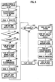
Fig. 3] Fig. 3 is a cross-sectional view along a line III - III inFig. 2 in the embodiment of the present invention. [Fig. 4] Fig. 4 is a flowchart showing processes at engine start-up in the embodiment of the present invention. - [
Fig. 5] Fig. 5 is a flowchart showing processes during operation of engine in the embodiment of the present invention. [Fig. 6] Fig. 6 is a table showing states of an SBW system and an SBW backup system in the embodiment of the present invention. - A description will be made below of an embodiment of the present invention based on the drawings.
- As shown in
Fig. 1 , a steering apparatus for avehicle 1 includes: [a] a steering wheel (steering device) 2 operated by a driver; [b] asteering angle sensor 3 for detecting an operating amount of thesteering wheel 2 as an electric signal; [c] a torque sensor 4 for detecting torque of thesteering wheel 2; [d] a steering reaction force generator 5 for generating reaction force to thesteering wheel 2; [e] asteering mechanism 6 for changing a steering angle ofroad wheels 10; [f] an electromagnetic clutch (connecting mechanism) 8 for connecting thesteering wheel 2 and thesteering mechanism 6 mechanically with a wire 7; [g] an SBW control unit 9 for receiving a vehicle speed (V) signal, a yaw rate (ω) signal, a lateral acceleration (G) signal or the like as an in-vehicle LAN signal as well as a torque signal and a steering angle signal mentioned above; and [h] abattery 30 for supplying electric power to the above-described components. - In a connected state of the
electromagnetic clutch 8, theelectromagnetic clutch 8 conducts the operating amount of thesteering wheel 2 to the wire 7 and thesteering mechanism 6 steers theroad wheels 10 based on the operating amount mechanically inputted thereto. Theelectromagnetic clutch 8 is controlled by the SBW control unit 9. Theelectromagnetic clutch 8 is set in a disconnected state while it is energized or set in the connected state while it is not energized. - During an SBW mode in which the
electromagnetic clutch 8 is in the disconnected state, the SBW control unit 9 controls thesteering mechanism 6 based on the steering angle signal from thesteering angle sensor 3 to steer theroad wheels 10 by a steering actuator (not shown) provided in thesteering mechanism 6 according to the operating amount of thesteering wheel 2. In addition, the SBW control unit 9 controls the steering reaction force generator 5 based on the torque signal from the torque sensor 4 and so on to enable an operation of thesteering wheels 2 with appropriate torque. Furthermore, the SBW control unit 9 shifts to an SBW backup mode to switch theelectromagnetic clutch 8 from the disconnected state to the connected state when the SBW control unit 9 has determined that the SBW mode cannot be executed properly due to a system malfunction of electrical equipment, an SBW system or the like. - In other words, the steering apparatus is provided with the SBW system for executing the SBW mode and the SBW backup system for executing the SBW backup mode.
- Next, a configuration of the
electromagnetic clutch 8 will be described in detail. As shown inFig. 2 andFig. 3 , theelectromagnetic clutch 8 includes: ashaft 13 supported rotatably in ahousing 11 via abearing 12 interposed therebetween and connected with anoutput shaft 2a (shown inFig. 1 ) on thesteering wheel 2 side; and anoutput pulley 15 supported rotatably and coaxially with theshaft 13 in thehousing 11 via abearing 14 interposed therebetween. Aninner wire 31 of the wire 7 connected to thesteering mechanism 6 is wound around theoutput pulley 15 to transmit rotation of an after-mentionedinternal gear ring 17 to thesteering mechanism 6. Aprotrusion 13a is provided on one end of theshaft 13 and a circular-arc rotating protrusion 16 is provided around theprotrusion 13a. - The
internal gear ring 17 is fixed to theoutput pulley 15 with opposing to theshaft 13 and supported rotatably around a center axis of theshaft 13.Internal teeth 17a are provided on an inner circumference of theinternal gear ring 17. Anexternal gear ring 18 has acenter hole 19 penetrated by theprotrusion 13a of theshaft 13 and is disposed between theshaft 13 and theinternal teeth 17a of theinternal gear ring 17.External teeth 18a are provided on an outer circumferential surface of theexternal gear ring 18. Thecenter hole 19 is formed to be larger than an outer diameter of theprotrusion 13a of theshaft 13. Theexternal gear ring 18 is eccentrically located with respect to theinternal gear ring 17 so that theexternal teeth 18a can be intermeshed with theinternal teeth 17a. - As shown in detail in
Fig. 3 ,lock members 20 are disposed within a space between the outer circumference of theshaft 13 and theexternal gear ring 18, and eccentrically-located to make theexternal gear teeth 18a of theexternal ring 18 intermeshed with theinternal teeth 17a. Thelock members 20 are composed of a pair oflock pieces 20a and one end of each of thelock pieces 20a extends close to therotating protrusion 16. It is an unlocked state that aspool 23 is not projected between the pair oflock pieces 20a and the pair oflock pieces 20a is contacted each other. Otherwise, as shown inFig. 3 , it is a locked state that thespool 23 is projected between the pair oflock pieces 20a and the pair oflock pieces 20a is separated each other. - At an unlock position, since each of the
lock pieces 20a is not wedged between theexternal gear ring 18 and theprotrusion 13a, the pair oflock pieces 20a are rotated by being pushed by therotating protrusion 16 in sliding contact with theexternal gear ring 18 when theshaft 13 rotates. In this case, theexternal gear ring 18 is rotated with intermeshed with theinternal gear ring 17 by 20a. At a lock position, each of thelock pieces 20a is wedged between theexternal gear ring 18 and theprotrusion 13a. Furthermore, since theexternal teeth 18a are intermeshed with theinternal teeth 17a, the pair oflock pieces 20a restrains theexternal gear ring 18 from moving in a radial direction to make the distance between the outer circumference of theprotrusion 13a of theshaft 13 and theexternal teeth 18a of theexternal gear ring 18 constant. As a result, the pair oflock pieces 20a and theexternal gear ring 18 rotate integrally to rotate theoutput pulley 15 via theinternal gear ring 17 by intermeshing of the gear rings when theshaft 13 rotates. - Note that, a
ring spring 21 is provided between the pair oflock pieces 20a. The pair oflock pieces 20a are urged to the lock position to be spaced away each other by spring force of thering spring 21. However, the spring force is so small that one of thelock pieces 20a can be moved to the unlock position by pressing force from the rotatingprotrusion 16. Specifically, thering spring 21 only prevents the pair oflock pieces 20a from rattling. - As shown in
Fig. 2 andFig. 3 , thespool 23 is provided on theshaft 13 and is disposed on a rotation orbit of the pair oflock pieces 20a and between the pair oflock pieces 20a. Since theshaft 13 and the pair oflock pieces 20a are always synchronized to rotate each other, a relative position between thespool 23 and the pair oflock pieces 20a is not changed. In addition, thespool 23 is provided to be able to projected-into and retracted-from a space between the pair oflock pieces 20a by turning on/off anelectromagnetic solenoid 24. A tip end of thespool 23 is tapered off to a point and able to projected into the space between the pair oflock pieces 20a smoothly and surely. - The
electromagnetic solenoid 24 has aspring 25 for urging thespool 23 to the lock position and anelectromagnet 26 for projecting thespool 23 to the unlock position by electromagnetic force. Theelectromagnet 26 is composed of anelectromagnetic coil 27 and aniron core 28. - The
electromagnetic solenoid 24 is turned on by energization of theelectromagnetic coil 27 to retract thespool 23 to the unlock position by theelectromagnet 26. The pair oflock pieces 20a rotates together with contacted each other by the rotatingprotrusion 16 when theshaft 13 is rotated (the spring force of thering spring 21 is so small that the pair oflock pieces 20a is easily contacted each other by the rotating protrusion 16). Theexternal gear ring 18 rotates with displacing its meshing position with theinternal gear ring 17 by the pair oflock pieces 20a rotating together with theshaft 13. At this time, the pair oflock pieces 20a and theexternal gear ring 18 slip each other. Therefore, theelectromagnetic clutch 8 is set to the disconnected state while theelectromagnetic solenoid 24 is energized. - The
electromagnetic solenoid 24 is turned off by non-energization of theelectromagnetic coil 27 to project thespool 23 to the lock position by the spring force of thespring 25. Since the pair oflock pieces 20a is positioned at the lock position after thespool 23 has been positioned at the lock position, the pair oflock pieces 20a is wedged between theprotrusion 13a and theexternal gear ring 18. And then, theexternal gear ring 18 and theshaft 13 rotate integrally. At this time, since theexternal gear ring 18 and theinternal gear ring 17 are already intermeshed each other, each of theexternal gear ring 18 and theinternal gear ring 17 rotate immediately together with the rotation of theshaft 13. As a result, the steering force onto thesteering wheel 2 is conducted to thesteering mechanism 6 via theelectromagnetic clutch 8 and the wire 7. Therefore, theelectromagnetic clutch 8 is set to the connected state while theelectromagnetic solenoid 24 is not energized. - Next, functions of the above-described
steering apparatus 1 will be described based onFig. 4 andFig. 5 . As shown inFig. 4 , since electrical supply to the SBW backup system is shut off when an engine is stopped, theelectromagnetic solenoid 24 of theelectromagnetic clutch 8 is turned off and thespool 23 is projected to the lock position. In such a way, the SBW backup system is turned on (Steps S1 to S4). - Since electric power is supplied from the
battery 30 to the SBW system and the SBW backup system when ACC (accessory) is selected, theelectromagnetic solenoid 24 of theelectromagnetic clutch 8 is turned on and thespool 23 is retracted at the unlock position. In such a way, the SBW backup system is turned off (Steps S5 to S11). - Next, the SBW control unit 9 determines whether or not the SBW system is to be able to be executed properly (Step S12). Whether or not the SBW system can be executed properly is determined by checking malfunction in the SBW system and the electronic component system. In checking the SBW system malfunction, for example, the SBW control unit 9 accesses the
steering angle sensor 3, the torque sensor 4 and thesteering mechanism 6 to get various information. And then, the SBW control unit 9 checks whether or not there is a mismatch between information on thesteering wheel 2 and information on thewheels 10. Then, the SBW control unit 9 determines that the SBW system malfunction occurs when the mismatch is found. The SBW control unit 9 determines that the SBW system malfunction occurs also when an electric power voltage of thebattery 30 is equal to or less than a prescribed level. - If it has been determined that the SBW control unit 9 can execute the SBW system properly, start of engine is allowed (Step S13). Specifically, if it has been determined that the SBW system can be executed properly, the SBW control unit 9 selects the SBW mode to disconnect the
electromagnetic clutch 8 by the energization of theelectromagnetic coil 27. The mechanical disconnection between thesteering wheel 2 and thesteering mechanism 6 is kept. Then, the SBW control unit 9 drives thesteering mechanism 6 according to the electric variable detected by thesteering angle sensor 3 to steer theroad wheels 10 when thesteering wheel 2 is steered. - If it has been determined that the SBW control unit 9 cannot execute the SBW system properly, the SBW system is turned off. Specifically, the SBW control unit 9 shuts off the electrical supply to the SBW system and the SBW backup system. As a result, the
electromagnetic solenoid 24 of theelectromagnetic clutch 8 is turned off and thespool 23 is projected to the lock position to turn on the SBW backup system (Steps S14 to S19). And then, start of engine is allowed (Step S12). Specifically, if it has been determined that the SBW system cannot be executed properly, the SBW control unit 9 shifts to the SBW backup mode. Then, theelectromagnetic clutch 8 is switched from the disconnected state to the connected state by the non-energization of theelectromagnetic coil 27. Then, the steering force onto thesteering wheel 2 is conducted to thesteering mechanism 6 via theelectromagnetic clutch 8 to steer theroad wheels 10 by thesteering mechanism 6. - As shown in
Fig. 5 , the SBW control unit 9 always checks whether or not the SBW system is being able to be executed properly during operation of engine after the SBW system was turned on at start of engine (Steps S20 to S22). - If it has been determined that the SBW system can be executed properly, the SBW control unit 9 continues the SBW mode. Specifically, the SBW control unit 9 continues to supply the electric power to the SBW system and the SBW backup system. Then, the
electromagnetic solenoid 24 of theelectromagnetic clutch 8 is kept turned on by continuing the energization of theelectromagnetic coil 27 and thespool 23 is kept retracted at the unlock position. In such a way, the SBW backup system is kept turned off (Steps S23 to S27). An operation lamp of the SBW system is turned on under the SBW mode and operation of engine is continued (Steps S28 and S29). - If it has been determined that the SBW system cannot be executed properly, the SBW control unit 9 turns off the SBW system. Specifically, the SBW control unit 9 shuts off the electrical supply to the SBW system and the SBW backup system. As a result, the
electromagnetic solenoid 24 of theelectromagnetic clutch 8 is turned off and thespool 23 is projected to the lock position to turn on the SBW backup system (Steps S30 to S35). The operation lamp of the SBW system is turned off under the SBW backup mode and operation of engine is continued (Steps S36 and S37). - Basically, as shown in
Fig. 6 , the SBW backup system is turned off when the SBW system is turned on and the SBW backup system is turned on when the SBW system is turned off. - According to the
steering apparatus 1 described above, since theelectromagnetic clutch 8 is set to the connected state during the non-energization, theelectromagnetic clutch 8 can be set to the connected state and the SBW backup system can be activated unfailingly when the electrical supply to the SBW control unit 9 is stopped. In addition, since whether or not the SBW mode can be executed properly is checked at start of engine and during operation of engine, the backup system can be activated unfailingly even when the system is out of order. - In the present embodiment, if it has been determined that the SBW mode cannot be executed properly, the energization of the
electromagnetic clutch 8 is stopped by turning off the electric power to the SBW control unit 9 itself. Therefore, the SBW control unit 9 does not execute an abnormal control while the backup system by theelectromagnetic clutch 8 is activated because the electric power is not supplied to the SBW control unit 9. In other words, the reaction force application to thesteering wheel 2 by the steering reaction force generator 5 based on the torque sensor 4, which must be executed under the SBW mode, can be prevented unfailingly under the SBW backup mode. - In the present embodiment, since the case where the SBW mode cannot be executed properly includes the malfunction in the SBW system and the electronic component system, the SBW backup system is activated even when the electronic component system malfunction occurs. Therefore, emergency escape running can be obtained by steering operation under mechanical connection.
- In the present embodiment, the SBW control unit 9 checks whether or not the SBW mode can be executed properly under the disconnected state of the
electromagnetic clutch 8 by the energization when an electrical supply to the vehicle is started at start of engine. If it has been determined that the SBW mode can be executed properly, the SBW control unit 9 continues the energization of theelectromagnetic clutch 8 to keep the disconnected state of theelectromagnetic clutch 8. If it has been determined that the SBW mode cannot be executed properly, the SBW control unit 9 stops the energization of theelectromagnetic clutch 8 to set theelectromagnetic clutch 8 to the connected state. Therefore, if it has been determined that the SBW mode can be executed properly when start of engine is selected, the SBW control unit 9 can activate the SBW system immediately without any waiting time. - Note that, in the present embodiment, the connecting mechanism is composed of the
electromagnetic clutch 8. However, the connecting mechanism is not limited to this. - According to the steering apparatus for a vehicle of the present invention, the connecting mechanism is set to the connected state by the non-energization. Therefore, when the electrical supply to the steer-by-wire control unit is stopped, the connecting mechanism can be set to the connected state unfailingly to activate the backup system.
Claims (4)
- A steering apparatus for a vehicle capable of executing a steer-by-wire mode in which road wheels are steered by a steering mechanism mechanically disconnected with a steering device, the apparatus comprising:a connecting mechanism which mechanically connects the steering device and the steering mechanism; anda steer-by-wire control unit whichwherein
sets the connecting mechanism to a disconnected state to control the steering mechanism based on an operating amount of the steering device under the steer-by-wire mode, and
sets the connecting mechanism to a connected state to switch a steering mode from the steer-by-wire mode to a steer-by-wire backup mode when it has been determined that the steer-by-wire mode cannot be executed properly,
the connecting mechanism is set to the disconnected state while being energized and set to the connected state while being non-energized, and
the steer-by-wire control unit checks whether or not the steer-by-wire mode can be executed properly at start of engine and always during operation of engine. - The steering apparatus according to claim 1, wherein
the steer-by-wire control unit shuts off electric power to itself to stop energizing the connecting mechanism when it has been determined that the steer-by-wire mode cannot be executed properly. - The steering apparatus according to claim 2, wherein
a case where the steer-by-wire mode cannot be executed properly includes a steer-by-wire system malfunction and an electronic component system malfunction. - The steering apparatus according to claim 1, wherein
the steer-by-wire control unit
checks whether or not the steer-by-wire mode can be executed properly under the disconnected state of the connecting mechanism by energizing when an electrical supply to the vehicle is started at start of engine,
continues energizing the connecting mechanism to keep the disconnected state of the connecting mechanism when it has been determined that the steer-by-wire mode can be executed properly, and
stops energizing the connecting mechanism to set the connecting mechanism to the connected state when it has been determined that the steer-by-wire mode cannot be executed properly.
Applications Claiming Priority (2)
| Application Number | Priority Date | Filing Date | Title |
|---|---|---|---|
| JP2005210592A JP2007022461A (en) | 2005-07-20 | 2005-07-20 | Vehicle steering system |
| PCT/JP2006/313840 WO2007010790A1 (en) | 2005-07-20 | 2006-07-12 | Vehicle steering device |
Publications (3)
| Publication Number | Publication Date |
|---|---|
| EP1905671A1 true EP1905671A1 (en) | 2008-04-02 |
| EP1905671A4 EP1905671A4 (en) | 2009-08-05 |
| EP1905671B1 EP1905671B1 (en) | 2010-09-29 |
Family
ID=37668672
Family Applications (1)
| Application Number | Title | Priority Date | Filing Date |
|---|---|---|---|
| EP06781010A Ceased EP1905671B1 (en) | 2005-07-20 | 2006-07-12 | Steering apparatus for vehicle |
Country Status (6)
| Country | Link |
|---|---|
| US (1) | US20090260913A1 (en) |
| EP (1) | EP1905671B1 (en) |
| JP (1) | JP2007022461A (en) |
| CN (1) | CN101223074B (en) |
| DE (1) | DE602006017221D1 (en) |
| WO (1) | WO2007010790A1 (en) |
Families Citing this family (10)
| Publication number | Priority date | Publication date | Assignee | Title |
|---|---|---|---|---|
| JP2009269468A (en) * | 2008-05-07 | 2009-11-19 | Jtekt Corp | Vehicular steering device |
| JP5120065B2 (en) * | 2008-05-26 | 2013-01-16 | 株式会社ジェイテクト | Vehicle control device |
| JP5510255B2 (en) * | 2010-10-01 | 2014-06-04 | トヨタ自動車株式会社 | Vehicle operation state determination system |
| KR20130064540A (en) * | 2011-12-08 | 2013-06-18 | 현대자동차주식회사 | System and method for controlling electric power steering apparatus of vehicle |
| WO2014068633A1 (en) * | 2012-10-29 | 2014-05-08 | トヨタ自動車株式会社 | Clutch device, and steering device for vehicle |
| WO2014108966A1 (en) * | 2013-01-11 | 2014-07-17 | 日産自動車株式会社 | Steering control device and steering control method |
| US10583856B2 (en) * | 2015-07-31 | 2020-03-10 | Nissan Motor Co., Ltd. | Steer-by-wire system, and control method for steer-by-wire system |
| JP6533772B2 (en) * | 2016-11-29 | 2019-06-19 | 本田技研工業株式会社 | Steering device |
| JP2018103731A (en) * | 2016-12-26 | 2018-07-05 | 株式会社オートネットワーク技術研究所 | Control apparatus for steering system |
| JP7204959B2 (en) * | 2020-02-05 | 2023-01-16 | 日立Astemo株式会社 | Steer-by-wire steering input device |
Family Cites Families (24)
| Publication number | Priority date | Publication date | Assignee | Title |
|---|---|---|---|---|
| JPH0622151U (en) * | 1992-08-28 | 1994-03-22 | カヤバ工業株式会社 | Power steering system |
| JPH10211885A (en) * | 1997-01-30 | 1998-08-11 | Koyo Seiko Co Ltd | Steering device for automobile |
| DE19755044C1 (en) * | 1997-12-11 | 1999-03-04 | Daimler Benz Ag | Motor vehicle steering arrangement |
| DE19827869A1 (en) * | 1998-06-23 | 1999-12-30 | Bosch Gmbh Robert | Steering system for motor vehicles |
| DE19841913A1 (en) * | 1998-09-14 | 2000-03-16 | Bosch Gmbh Robert | Electromechanical steering adjuster, especially for steer-by-wire use in cars has switchable clutch which upon occurrence of fault in steering system connects steering wheel in positive locking fashion to controlled member |
| JP3824477B2 (en) * | 1999-11-24 | 2006-09-20 | 株式会社ジェイテクト | Vehicle steering system |
| JP2001301639A (en) * | 2000-04-24 | 2001-10-31 | Nissan Motor Co Ltd | Vehicle steering system |
| JP3830331B2 (en) * | 2000-05-31 | 2006-10-04 | 株式会社ジェイテクト | Vehicle steering system |
| JP3856636B2 (en) * | 2000-10-11 | 2006-12-13 | 株式会社ジェイテクト | Vehicle steering system |
| JP3897971B2 (en) * | 2000-10-20 | 2007-03-28 | 株式会社ジェイテクト | Vehicle steering system |
| JP4419114B2 (en) * | 2000-11-14 | 2010-02-24 | 株式会社ジェイテクト | Vehicle steering system |
| JP2002225733A (en) * | 2001-01-29 | 2002-08-14 | Koyo Seiko Co Ltd | Vehicle steering system |
| JP2003146230A (en) * | 2001-11-12 | 2003-05-21 | Koyo Seiko Co Ltd | Steering gear |
| JP2003170843A (en) * | 2001-12-05 | 2003-06-17 | Koyo Seiko Co Ltd | Steering device for vehicle |
| JP4147836B2 (en) * | 2002-06-21 | 2008-09-10 | 株式会社ジェイテクト | Vehicle steering system |
| US6580989B1 (en) * | 2002-08-20 | 2003-06-17 | Visteon Global Technologies, Inc. | Motor vehicle steering system |
| DE10302559A1 (en) * | 2003-01-22 | 2004-09-09 | Daimlerchrysler Ag | Method for the synchronization of steering handle and steered vehicle wheels |
| JP2004237785A (en) * | 2003-02-04 | 2004-08-26 | Honda Motor Co Ltd | Vehicle steering system |
| JP2004351975A (en) * | 2003-05-27 | 2004-12-16 | Ntn Corp | Fail-safe mechanism of steer-by-wire system and steer-by-wire system |
| DE602004025068D1 (en) * | 2003-06-11 | 2010-03-04 | Nissan Motor | Fail-safe steering system for a motor vehicle |
| JP4218437B2 (en) * | 2003-06-19 | 2009-02-04 | マツダ株式会社 | Seal structure for automotive window members |
| JP2005008073A (en) * | 2003-06-19 | 2005-01-13 | Ntn Corp | Failsafe mechanism of by-wire steering system and a by-wire steering system |
| JP2005096559A (en) * | 2003-09-24 | 2005-04-14 | Toyoda Mach Works Ltd | Vehicle steering system |
| JP2005132327A (en) * | 2003-10-10 | 2005-05-26 | Honda Motor Co Ltd | Vehicle steering system |
-
2005
- 2005-07-20 JP JP2005210592A patent/JP2007022461A/en active Pending
-
2006
- 2006-07-12 US US11/989,007 patent/US20090260913A1/en not_active Abandoned
- 2006-07-12 CN CN2006800259804A patent/CN101223074B/en not_active Expired - Fee Related
- 2006-07-12 DE DE602006017221T patent/DE602006017221D1/en active Active
- 2006-07-12 EP EP06781010A patent/EP1905671B1/en not_active Ceased
- 2006-07-12 WO PCT/JP2006/313840 patent/WO2007010790A1/en not_active Ceased
Also Published As
| Publication number | Publication date |
|---|---|
| US20090260913A1 (en) | 2009-10-22 |
| EP1905671B1 (en) | 2010-09-29 |
| WO2007010790A1 (en) | 2007-01-25 |
| CN101223074B (en) | 2010-08-18 |
| DE602006017221D1 (en) | 2010-11-11 |
| JP2007022461A (en) | 2007-02-01 |
| CN101223074A (en) | 2008-07-16 |
| EP1905671A4 (en) | 2009-08-05 |
Similar Documents
| Publication | Publication Date | Title |
|---|---|---|
| JP3780985B2 (en) | Steering control device for vehicle | |
| US6164150A (en) | Vehicle steering apparatus | |
| US7243570B2 (en) | Power-assisted steering with electric motor locking device | |
| EP1905671B1 (en) | Steering apparatus for vehicle | |
| JP6630252B2 (en) | Vehicle control device | |
| JP5673630B2 (en) | Steering device | |
| CN1974294A (en) | Steering apparatus | |
| US7946195B2 (en) | Steering apparatus for vehicle | |
| US7770688B2 (en) | Device for superimposing rotational speeds for a steering system | |
| US9359003B2 (en) | Clutch device and steering device | |
| JP2005526661A (en) | Override device for override steering system | |
| JP4968085B2 (en) | Parking switching device | |
| JP2008273419A (en) | Vehicle steering control device | |
| JP2014054916A (en) | Steering gear | |
| JP2005178460A (en) | Vehicle steering system | |
| CN115703502A (en) | Electric power steering apparatus | |
| JP2007203799A (en) | Transmission ratio variable device | |
| JP4802641B2 (en) | Vehicle steering system | |
| JP3969237B2 (en) | Lock control device | |
| JP4211311B2 (en) | Steering device | |
| JP2004224096A (en) | Electric power steering device | |
| JP2007062655A (en) | Vehicle steering system | |
| JP3969044B2 (en) | Vehicle steering device | |
| JP2006044485A (en) | Vehicle steering device | |
| JP3824477B2 (en) | Vehicle steering system |
Legal Events
| Date | Code | Title | Description |
|---|---|---|---|
| PUAI | Public reference made under article 153(3) epc to a published international application that has entered the european phase |
Free format text: ORIGINAL CODE: 0009012 |
|
| 17P | Request for examination filed |
Effective date: 20080131 |
|
| AK | Designated contracting states |
Kind code of ref document: A1 Designated state(s): DE FR |
|
| DAX | Request for extension of the european patent (deleted) | ||
| RBV | Designated contracting states (corrected) |
Designated state(s): DE FR |
|
| A4 | Supplementary search report drawn up and despatched |
Effective date: 20090702 |
|
| RAP1 | Party data changed (applicant data changed or rights of an application transferred) |
Owner name: JTEKT CORPORATION |
|
| GRAP | Despatch of communication of intention to grant a patent |
Free format text: ORIGINAL CODE: EPIDOSNIGR1 |
|
| GRAC | Information related to communication of intention to grant a patent modified |
Free format text: ORIGINAL CODE: EPIDOSCIGR1 |
|
| GRAS | Grant fee paid |
Free format text: ORIGINAL CODE: EPIDOSNIGR3 |
|
| GRAA | (expected) grant |
Free format text: ORIGINAL CODE: 0009210 |
|
| AK | Designated contracting states |
Kind code of ref document: B1 Designated state(s): DE FR |
|
| REF | Corresponds to: |
Ref document number: 602006017221 Country of ref document: DE Date of ref document: 20101111 Kind code of ref document: P |
|
| PLBE | No opposition filed within time limit |
Free format text: ORIGINAL CODE: 0009261 |
|
| STAA | Information on the status of an ep patent application or granted ep patent |
Free format text: STATUS: NO OPPOSITION FILED WITHIN TIME LIMIT |
|
| REG | Reference to a national code |
Ref country code: DE Ref legal event code: R097 Ref document number: 602006017221 Country of ref document: DE Effective date: 20110630 |
|
| REG | Reference to a national code |
Ref country code: FR Ref legal event code: PLFP Year of fee payment: 11 |
|
| REG | Reference to a national code |
Ref country code: FR Ref legal event code: PLFP Year of fee payment: 12 |
|
| REG | Reference to a national code |
Ref country code: FR Ref legal event code: PLFP Year of fee payment: 13 |
|
| PGFP | Annual fee paid to national office [announced via postgrant information from national office to epo] |
Ref country code: FR Payment date: 20230620 Year of fee payment: 18 |
|
| PGFP | Annual fee paid to national office [announced via postgrant information from national office to epo] |
Ref country code: DE Payment date: 20230531 Year of fee payment: 18 |
|
| REG | Reference to a national code |
Ref country code: DE Ref legal event code: R119 Ref document number: 602006017221 Country of ref document: DE |
|
| PG25 | Lapsed in a contracting state [announced via postgrant information from national office to epo] |
Ref country code: DE Free format text: LAPSE BECAUSE OF NON-PAYMENT OF DUE FEES Effective date: 20250201 |
|
| PG25 | Lapsed in a contracting state [announced via postgrant information from national office to epo] |
Ref country code: FR Free format text: LAPSE BECAUSE OF NON-PAYMENT OF DUE FEES Effective date: 20240731 |