EP1905670A2 - Electric power steering apparatus - Google Patents
Electric power steering apparatus Download PDFInfo
- Publication number
- EP1905670A2 EP1905670A2 EP07117174A EP07117174A EP1905670A2 EP 1905670 A2 EP1905670 A2 EP 1905670A2 EP 07117174 A EP07117174 A EP 07117174A EP 07117174 A EP07117174 A EP 07117174A EP 1905670 A2 EP1905670 A2 EP 1905670A2
- Authority
- EP
- European Patent Office
- Prior art keywords
- steering
- vehicle
- assist force
- case
- torque
- Prior art date
- Legal status (The legal status is an assumption and is not a legal conclusion. Google has not performed a legal analysis and makes no representation as to the accuracy of the status listed.)
- Granted
Links
Images


Classifications
-
- B—PERFORMING OPERATIONS; TRANSPORTING
- B62—LAND VEHICLES FOR TRAVELLING OTHERWISE THAN ON RAILS
- B62D—MOTOR VEHICLES; TRAILERS
- B62D5/00—Power-assisted or power-driven steering
- B62D5/04—Power-assisted or power-driven steering electrical, e.g. using an electric servo-motor connected to, or forming part of, the steering gear
- B62D5/0457—Power-assisted or power-driven steering electrical, e.g. using an electric servo-motor connected to, or forming part of, the steering gear characterised by control features of the drive means as such
- B62D5/046—Controlling the motor
- B62D5/0463—Controlling the motor calculating assisting torque from the motor based on driver input
-
- B—PERFORMING OPERATIONS; TRANSPORTING
- B62—LAND VEHICLES FOR TRAVELLING OTHERWISE THAN ON RAILS
- B62D—MOTOR VEHICLES; TRAILERS
- B62D6/00—Arrangements for automatically controlling steering depending on driving conditions sensed and responded to, e.g. control circuits
- B62D6/002—Arrangements for automatically controlling steering depending on driving conditions sensed and responded to, e.g. control circuits computing target steering angles for front or rear wheels
- B62D6/003—Arrangements for automatically controlling steering depending on driving conditions sensed and responded to, e.g. control circuits computing target steering angles for front or rear wheels in order to control vehicle yaw movement, i.e. around a vertical axis
-
- B—PERFORMING OPERATIONS; TRANSPORTING
- B62—LAND VEHICLES FOR TRAVELLING OTHERWISE THAN ON RAILS
- B62D—MOTOR VEHICLES; TRAILERS
- B62D6/00—Arrangements for automatically controlling steering depending on driving conditions sensed and responded to, e.g. control circuits
- B62D6/008—Control of feed-back to the steering input member, e.g. simulating road feel in steer-by-wire applications
Definitions
- the present invention relates to an electric power steering apparatus.
- Japanese Laid-Open Patent Publication No. 2002-104219 discloses an EPS having a torque sensor 23 which detects steering torque on the basis of the torsion angle of a torsion bar 22 provided in the middle of the steering transmission system (a steering shaft 21) connecting the steering wheel and the steered wheels, as shown in Fig. 9.
- This EPS controls the assist force provided in the steering system on the basis of the steering torque detected by the torque sensor 23.
- FIG. 9 is a diagram schematically showing the configuration of a sensor which is widely adopted as a torque sensor for EPS's, that is to say, a twin resolver type torque sensor for detecting the torsion angle of the torsion bar 22 by means of a pair of angle sensors 24a and 24b (resolvers) provided at both ends of the torsion bar 22.
- a torque sensor for EPS's that is to say, a twin resolver type torque sensor for detecting the torsion angle of the torsion bar 22 by means of a pair of angle sensors 24a and 24b (resolvers) provided at both ends of the torsion bar 22.
- the orientation of the vehicle sometimes deflects due to a lack of, for example, weight balance or braking force balance, despite the fact that the steering angle is constant, for example when the brakes are applied during straight driving.
- self aligning torque for turning the steered wheels in the direction opposite to the direction in which the vehicle deflects acts on the steered wheels.
- the self aligning torque acts on the steered wheels 26 in such a direction that the steered wheels 26 turn to the left, that is to say, in such a direction that the orientation of the vehicle is stabilized.
- the steering torque in the direction in which the vehicle deflects is detected by the torque sensor on the basis of the torsion of the torsion bar which is caused when the driver maintains the steering angle, that is to say, torsion of the torsion bar which is caused when the rotation of the steering wheel generated on the basis of the self aligning torque is restricted. Therefore, in vehicles having EPS, the EPS operates on the basis of the steering torque detected by the torque sensor, and thus, assist force is provided in such a direction that the self aligning torque which acts in such a direction as to stabilize the vehicle is canceled. As a result, a problem arises, such that the vehicle drifts in the direction in which the vehicle deflects.
- an electric power steering apparatus for a vehicle having a steering system and a torsion bar provided in the middle of a steering transmitting system connecting a steering wheel to a steered wheel.
- the apparatus includes a steering force assisting device having a motor, a torque sensor for detecting steering torque on the basis of the torsion angle of the torsion bar, a control section, and a deflection sensing section for sensing deflection in the orientation of the vehicle.
- the steering force assisting device provides assist force for assisting the steering operation of the steering system using the motor as a drive source.
- the control section controls the assist force generated by the steering force assisting device on the basis of the detected steering torque.
- the control section reduces the assist force generated by the steering force assisting device in the case where deflection is sensed at the time of braking of the vehicle.
- an electric power steering apparatus for a vehicle having a steering system and a torsion bar provided in the middle of a steering transmitting system connecting a steering wheel to a steered wheel.
- the apparatus includes a steering force assisting device having a motor, a torque sensor for detecting steering torque on the basis of the torsion angle of the torsion bar, and a control section.
- the steering force assisting device provides assist force for assisting the steering operation to the steering system using the motor as a drive source.
- the control section controls the assist force generated by the steering force assisting device on the basis of the detected steering torque.
- the control section reduces the assist force generated by the steering force assisting device in the case where the vehicle speed is a predetermined speed or higher at the time of braking of the vehicle.
- an electric power steering apparatus for a vehicle having a steering system and a torsion bar provided in the middle of a steering transmitting system connecting a steering wheel to a steered wheel.
- the apparatus includes a steering force assisting device having a motor, a torque sensor for detecting steering torque on the basis of the torsion angle of the torsion bar, a control section, and a deflection predicting section.
- the steering force assisting device provides assist force for assisting the steering operation to the steering system using the motor as a drive source.
- the control section controls the assist force generated by the steering force assisting device on the basis of the detected steering torque.
- the deflection predicting section predicts deflection in the orientation of the vehicle at the time of braking of the vehicle.
- the control section reduces the assist force generated by the steering force assisting device in the case where deflection is predicted.
- Fig. 1 is a diagram schematically showing the configuration of the electric power steering apparatus (EPS) 1 according to the present embodiment.
- EPS electric power steering apparatus
- a steering shaft 3 to which a steering wheel 2 is secured is connected to a rack 5 via a rack and pinion mechanism 4.
- Rotation of the steering shaft 3 accompanying operation of the steering wheel 2 is converted into linear reciprocation of the rack 5 by means of the rack and pinion mechanism 4.
- This linear reciprocation of the rack 5 changes the angle of the steered wheels 6, that is to say, the steered angle, and thus, the direction in which the vehicle moves changes.
- the EPS 1 is provided with an EPS actuator 10, which is a steering force assisting device for providing assist force to assist operation of the steering wheel 2 to the steering system, and an ECU 11, which is a control section for controlling the operation of this EPS actuator 10.
- an EPS actuator 10 which is a steering force assisting device for providing assist force to assist operation of the steering wheel 2 to the steering system
- an ECU 11 which is a control section for controlling the operation of this EPS actuator 10.
- the EPS actuator 10 is a rack assist type EPS actuator, in which a motor 12, which is a drive source for the system, is coaxially placed with the rack 5.
- the motor torque generated by the motor 12 is transmitted to the rack 5 via a ball screw mechanism (not shown).
- the motor 12 according to the present embodiment is a brushless motor which rotates when receiving supply of drive power in three phases (U, V and W) from the ECU 11.
- the ECU 11 controls operation of the EPS actuator 10, that is to say, assist force provided to the steering system, through the supply of drive power to the motor 12.
- a torque sensor 14 is provided in the middle of the steering shaft 3, which constitutes the steering transmission system between the steering wheel 2 and the steered wheels 6.
- Steering torque ⁇ which is detected by this torque sensor 14, is inputted into the ECU 11.
- a publicly known twin resolver type torque sensor having the same configuration as the torque sensor 23 shown in Fig. 9, that is to say, a torque sensor for detecting the steering torque ⁇ on the basis of the torsion angle of the torsion bar 22 provided in the middle of the steering shaft 3 (21) is used.
- Left and right wheel speeds V_L and V_R which are detected by wheel speed sensors 15L and 15R, and the vehicle speed V are input into the ECU 11.
- the ECU 11 controls the operation of the EPS actuator 10 in such a manner that assist force is generated in accordance with the steering torque ⁇ and the vehicle speed V, concretely, assist force which is greater when (the absolute value of) the steering torque ⁇ is greater and the vehicle speed V is lower is generated.
- the ECU 11 determines whether the orientation of the vehicle deflects at the time of braking. That is to say, the ECU 11 according to the present embodiment functions as a deflection sensing section. In addition, in the case where it is determined that the orientation of the vehicle is deflecting, the operation of the EPS actuator 10 is controlled in order to reduce the assist force provided to the steering system. In the following description, this control is referred to as orientation stabilizing control during braking.
- the ECU 11 first acquires state quantities, which are used for the orientation stabilizing control during braking (Step 101).
- the steering angle ⁇ s detected by the steering sensor 16 and the brake signal S_bk indicating whether a braking operation is being carried out, in addition to the above described steering torque ⁇ , the vehicle speed V, and the left and right wheel speeds V_L and V_R, are inputted into the ECU 11 according to the present embodiment.
- the ECU 11 determines whether the vehicle is being braked on the basis of the brake signal S_bk (Step 102). In the case where the vehicle is being braked (YES in Step 102), the ECU 11 determines whether the absolute value of the steering angle ⁇ s is smaller than the predetermined threshold value ⁇ 0, in other words, whether the steering angle is within a predetermined angle range in the vicinity of neutral, that is to say, whether the brakes are being applied in a state where the vehicle is moving approximately straight forward (Step 103).
- the ECU 11 determines whether the orientation of the vehicle is deflecting on the basis of the steering angle ⁇ s and the left and right wheel speeds V_L and V_R (Step 104). In the case where it is determined that the orientation of the vehicle is deflecting (YES in Step 104), control for reducing assist force generated by the EPS actuator 10 is carried out (Step 105).
- Step 106 In the case where the conditions for determination in the above described Steps 102 through 104 are not met, that is to say, in the case where it is determined that the brakes are not being applied (NO in Step 102), the absolute value of the steering angle ⁇ s is not smaller than the predetermined threshold value ⁇ 0 (NO in Step 103), or the orientation of the vehicle is not deflecting (NO in Step 104), the ECU 11 does not carry out the assist force reducing process in Step 105. In addition, the ECU 11 carries out normal control. That is to say, the ECU 11 controls the operation of the EPS actuator 10 in order to generate assist force in accordance with the steering torque ⁇ and the vehicle speed V (Step 106).
- the first embodiment has the following advantages.
- an ECU 11 detects the vehicle speed V and forward/backward acceleration (longitudinal acceleration) G of the vehicle as a vehicle state quantity.
- the detected forward/backward acceleration G has a value which indicates deceleration which is greater than a predetermined value G1 (a negative value in the case where a value in the direction in which the vehicle moves is defined as a positive value, that is to say G ⁇ -G1) and in the case where the vehicle speed V is greater than the predetermined speed V1
- the operation of the EPS actuator 10 is controlled in order to reduce the assist force provided to the steering system.
- the detected forward/rearward acceleration G has a value which indicates deceleration greater than the predetermined value G1 (for example -0.8 G), which is considered to be sudden application of the brakes causing deceleration no smaller than the predetermined deceleration
- the vehicle speed V has a value indicating that the vehicle is running at high speed no less than the predetermined speed V1 (for example 100 km/h)
- the possibility of the orientation of the vehicle deflecting as described above is extremely high.
- the ECU 11 which is a deflection predicting section according to the present embodiment, predicts that the orientation of the vehicle will deflect in the case described above (G ⁇ -G1 and V ⁇ V1).
- the assist force provided to the steering system is reduced in advance, that is to say, control for reducing assistance is carried out, before the predicted deflection occurs.
- the self aligning torque (SAT) generated afterwards that is to say, the SAT, which acts in such a direction as to stabilize the vehicle, is used effectively, so that the orientation of the vehicle is quickly stabilized.
- Step 201 when the ECU 11 acquires the state quantities (forward/backward acceleration G, vehicle speed V, steering torque ⁇ , and steering speed ⁇ s) used for orientation stabilizing control during braking (Step 201), it is first determined whether a reduction flag which indicates that control for reducing assistance should be carried out has already been set (Step 202).
- the steering angle speed ⁇ s is acquired by time differentiating the steering angle ⁇ .
- the ECU 11 predicts that the vehicle is in such a state that the orientation of the vehicle will easily deflect, that is to say, makes a determination and predicts that the vehicle will deflect (Steps 203 and 204).
- the ECU 11 determines in the deflection prediction determination whether the forward/backward acceleration G has a value which indicates deceleration greater than the predetermined value G1 (Step 203), and whether the vehicle speed V is the predetermined speed V1 or higher (Step 204).
- the forward/backward acceleration G has a value indicating deceleration greater than the predetermined value G1 and the vehicle speed V is the predetermined speed V1 or higher (YES in Step 203 and YES in Step 204: G ⁇ -G1 and V ⁇ V1)
- the ECU 11 predicts that the orientation of the vehicle will deflect, sets a reduction flag (Step 205), and carries out control for reducing the assistance (Step 206).
- the ECU 11 predicts that the orientation of the vehicle will not deflect.
- the ECU 11 carries out normal assist control without setting the reduction flag as described above. That is to say, the ECU 11 controls operation of the EPS actuator 10 in order to generate assist force in accordance with the steering torque ⁇ and the vehicle speed V (Step 207).
- the ECU 11 sets the assist force to "0" in the assistance reducing control in the case where (the absolute value of) the steering torque ⁇ is within a range corresponding to the self aligning torque generated when the vehicle deflects, that is to say, is smaller than the upper limit value ⁇ 0 of the steering torque ⁇ , which is detected as the self aligning torque (
- the solid lines L indicate the assistance properties at the time of normal assist control
- the broken lines M indicate the assistance properties at the time of the assistance reducing control.
- the steering torque ⁇ is this upper limit value ⁇ 0 or higher (
- the assist force is set to "0," and thus, the self aligning torque, which acts in such a direction as to stabilize the vehicle, can be used effectively without being weakened by this assist force.
- the steering torque ⁇ which exceeds the range corresponding to the self aligning torque generated when the vehicle deflects is detected, it is assumed that the driver is carrying out a certain steering operation. In such cases, the greater the steering torque ⁇ is, the greater the provided assist force is (assist force close to that at the time of normal assist control), and thus, the steering operation is assisted without giving the driver a sense of discomfort.
- Step 208 to 211 the ECU 11 subsequently determines whether the above described assistance reducing control should be canceled.
- the ECU 11 determines whether the forward/backward acceleration G is a value indicating deceleration which is smaller than the deceleration indicated by the predetermined value G2 (Step 208), whether the vehicle speed V is the predetermined speed V2 or lower (Step 209), and whether (the absolute value of) the steering speed ⁇ s is the predetermined speed ⁇ 1 or higher (Step 210) in this determination for canceling.
- the predetermined value G2 and the predetermined speed V2 are set in accordance with the lower limit value (for example -0.2 G and 80 km/h) in the region where it is predicted that the vehicle will easily deflect.
- the predetermined speed ⁇ 1 is set in accordance with the value where it is assumed that the driver has carried out a steering operation.
- the vehicle speed V is the predetermined speed V2 or lower (YES in Step 209: V ⁇ V2), or the steering speed ⁇ s is the predetermined speed ⁇ 1 or higher (YES in Step 210:
- the ECU 11 subsequently determines whether (the absolute value of) the steering torque ⁇ is the predetermined threshold value ⁇ 1 or lower (Step 211).
- Step 212 the reduction flag is reset in order to cancel the above described assistance reducing control (Step 212), and normal assist control (Step 207) is carried out.
- Step 211 the determination allows the manner for assist control to return from reduction control to normal control in a state where the steering torque ⁇ is relatively small, and as a result, the steering feel can be prevented from changing together with the switching of this assist control.
- the vehicle speed V is greater than the predetermined speed V2 (V > V2)
- the steering speed ⁇ s is smaller than the predetermined speed ⁇ 1 (
- the ECU 11 determines that the above described assistance reducing control should be continued.
- the above described reduction flag is not reset, and the assistance reducing control is carried out (Step 206).
- the second embodiment has the following advantages.
- the assist force in the case where it is predicted that the orientation of the vehicle will deflect, the assist force is set to "0," and thus, the self aligning torque, which acts in such a direction as to stabilize the vehicle, can be used effectively without being weakened by this assist force.
- the steering torque ⁇ is detected when it is assumed that the driver is carrying out a certain steering operation, the greater this steering torque ⁇ is, the greater the provided assist force becomes (assist force close to that at the time of normal assist control).
- the steering operation is assisted without giving the driver a feeling of discomfort.
- the assist force provided to the steering system is simply reduced.
- a configuration for reducing the assist force to "0" (Step 305) may be adopted.
- the self aligning torque which acts in such a direction as to stabilize the vehicle, can be used effectively without being weakened by the assist force.
- the process in Steps 301 to 304 and Step 306 in the flowchart of Fig. 5 are the same as the process in Steps 101 to 104 and Step 106 in the flowchart of Fig.
- the configuration where the assist force is reduced to "0" may be adopted.
- the assist force when the vehicle deflects is reduced in the case where the absolute value of the steering angle ⁇ s is smaller than the predetermined threshold value ⁇ 0 (see Fig. 2, Step 103).
- this condition may be omitted. That is to say, the orientation of the vehicle sometimes deflects without the driver's intent at the time of braking during turning, and such cases can be dealt with by omitting the above described condition that the vehicle be moving straight forward.
- Step 405 determination that the vehicle is in such a state as to be moving straight forward may be adopted, as in the first embodiment.
- the orientation of the vehicle is predicted to deflect as a result of the prediction of deflection in Steps 403 and 404 (YES in Step 403 and YES in Step 404: G ⁇ -G1 and V ⁇ V1)
- the determination of the steering angle conditions in this Step 405 is determination that the vehicle is in such a state as to be moving straight forward, where it is determined the steering angle ⁇ s is within a predetermined angle range in the vicinity of neutral, that is to say, whether the brakes are being applied in such a state that the vehicle is moving approximately straight forward, in the same manner as the conditions for determining the steering angle according to the first embodiment (see Fig. 2, Step 103).
- a reduction flag is set (Step 406) and the assistance reducing control is carried out (Step 407).
- control for normal assistance may be carried out without setting the reduction flag.
- the assist force may be reduced when the state of the vehicle is limited to one where the vehicle is moving straight forward, as described above, and thus, the above described specific cases (for example intentional operation by the driver) can be excluded, and the orientation of the vehicle is prevented from deflecting in a manner not intended by the driver with high precision.
- steering angle condition may be added to the determination for canceling the assistance reducing control. That is to say, as shown in Fig. 6, determination of the steering angle condition (Step 412) is carried out subsequent to the determination of the acceleration (deceleration) condition, the determination of the speed condition, and the determination of steering speed condition (Steps 409 to 411).
- the steering angle ⁇ s is the predetermined threshold value ⁇ 1 or larger in the determination of the steering angle condition in Step 412 (YES in Step 412:
- the reduction flag is reset (Step 413).
- Steps 401 to 404, Steps 406 to 408, Steps 409 to 411, Step 413 and Step 414 in the flowchart of Fig. 6 are the same as the processes in Steps 201 to 204, Steps 205 to 207, Steps 208 to 210, Step 211 and Step 212 in the flowchart of Fig. 3, respectively, and therefore, descriptions thereof are omitted.
- determination of the steering speed condition as that shown in Step 411 in Fig. 6 may be carried out so as to correspond to the determination of the conditions for commencing the assistance reducing control, which is carried out subsequently to the above described sensing of the change or prediction of deflection, that is to say, the determination of the steering angle condition shown in Step 405 in Fig. 6. That is to say, in the case where (the absolute value of) the steering speed ⁇ s is the predetermined speed ⁇ 1 or higher (
- the determination as to whether the orientation of the vehicle is deflecting is carried out on the basis of the steering angle ⁇ s and the left and right wheel speeds V_L and V_R.
- the manner for determination is not limited to this, and the above described determination, may be carried out in, for example, a vehicle having a yaw rate sensor, through detection of the actual yaw rate.
- the above described yaw rate condition and the wheel speed difference condition may be added to the prediction that the vehicle will deflect also in the case where the assist force is reduced on the basis of the prediction that the vehicle will deflect, as in the second embodiment.
- the prediction that the vehicle will deflect following the determination for the conditions for acceleration (or deceleration) (Step 503) and the determination of the speed condition (Step 504), it is determined whether (the absolute value of) the yaw rate ⁇ is the predetermined threshold value ⁇ 1 or higher (Step 505).
- the threshold value ⁇ 1 in terms of the yaw rate ⁇ in this case, to be the same as the threshold value in the case where the yaw rate condition is added to the determination as to whether deflection is sensed according to the above described first embodiment, and the threshold value may be an appropriate value for this "prediction.”
- the determination of the state where the vehicle is moving straight forward (Step 506) is carried out on the basis of the steering angle ⁇ s, and in the case where the steering angle condition is met (YES in Step 506:
- Step 506 the above described determination of the state where the vehicle is moving straight forward (Step 506) is not carried out and the reduction flag (Step 507) is not set, but the normal assistance control is carried out (Step 508).
- Step 506 the above described determination of the state where the vehicle is moving straight forward (Step 506) is not carried out and the reduction flag (Step 507) is not set, but the normal assistance control is carried out (Step 508).
- Step 506 determination of the state where the vehicle is moving straight forward
- Step 507 the reduction flag
- Step 508 the normal assistance control is carried out
- Steps 501 to 504 and Steps 506 to 515 in the flowchart of Fig. 7 are the same as the processes in Steps 401 to 404 and Steps 405 to 414 in the flowchart of Fig. 6, respectively, and therefore, descriptions thereof are omitted.
- the determination of the yaw rate condition in Step 506 in Fig. 7 may be changed to determination of the wheel speed difference or determination of yaw angle acceleration.
- determination of braking is carried out on the basis of the brake signal S_bk.
- the invention is not limited to this, and the above described determination may be carried out on the basis of the acceleration (or deceleration) gained by differentiating the vehicle speed V.
- determination of braking in accordance with prediction that the vehicle will deflect may be carried out depending on whether a braking operation is being carried out also in the case where the assist force is reduced on the basis of the prediction that the vehicle will deflect, as in the second embodiment.
- the process shown in the flowchart of Fig. 8, for example, may be adopted.
- Step 601 the vehicle speed V and the brake signal S_bk are acquired as the state quantities, which are used for the orientation stabilizing control during braking (Step 601).
- Step 602 it is determined whether a reduction flag is set (Step 602), and in the case where a reduction flag is not set (NO in Step 602), it is determined whether the brake signal S_bk is on (Step 603) and whether the vehicle speed V is the predetermined speed V1 or higher (Step 604).
- Step 605 the orientation of the vehicle is predicted to deflect and the reduction flag is set (Step 605).
- Step 606 the assistance reducing control is carried out.
- the orientation of the vehicle is predicted not to deflect.
- the above described reduction flag is not set, and the normal assistance control is carried out (Step 607).
- Step 608 S_bk is off
- V ⁇ V2 the vehicle speed V is the predetermined speed V2 or lower
- the reduction flag is reset in order to cancel the above described assistance reducing control (Step 610), and the normal assistance control is carried out (Step 607).
- Step 607 In the case where the brake signal S_bk is not off (NO in Step 608: S_bk is on) and the vehicle speed V is greater than the predetermined speed V2 (NO in Step 609: V > V2) in the above described Steps 608 and 609, the above described reduction flag is not reset, and the assistance reducing control (Step 607) is carried out.
- This configuration has the same advantages as the second embodiment, and furthermore, has an advantage such that it can be implemented with a simpler configuration.
- a case where the vehicle speed is the predetermined speed or higher or a case where the brakes are suddenly applied so that the deceleration is a predetermined deceleration or higher may be added as a condition for carrying out the assist force reducing control when the orientation of the vehicle deflects. That is to say, the orientation of the vehicle at the time of braking easily deflects when braking starts in a state where the vehicle is running at high speed or the brakes are suddenly applied. Accordingly, in the above described configurations, the orientation of the vehicle can be prevented from deflecting in a manner not intended by the driver with higher precision.
- the determinations of the conditions included in the determination for canceling the assistance reducing control may be changed as necessary.
- the determination for canceling includes the steering torque condition (see Fig. 3, Step 211), it is not necessary to adopt a configuration including this.
- An ECU determines whether the orientation of the vehicle is deflecting at the time of braking. In addition, in a case where it is determined that the orientation of the vehicle is deflecting, the ECU controls operation of an EPS actuator in order to reduce the assist force provided to the steering system.
Abstract
Description
- The present invention relates to an electric power steering apparatus.
- In recent years, electric power steering apparatuses (EPS) using a motor as a drive source have been widely adopted as power steering apparatuses for vehicles.
Japanese Laid-Open Patent Publication No. 2002-104219 torque sensor 23 which detects steering torque on the basis of the torsion angle of atorsion bar 22 provided in the middle of the steering transmission system (a steering shaft 21) connecting the steering wheel and the steered wheels, as shown in Fig. 9. This EPS controls the assist force provided in the steering system on the basis of the steering torque detected by thetorque sensor 23. Fig. 9 is a diagram schematically showing the configuration of a sensor which is widely adopted as a torque sensor for EPS's, that is to say, a twin resolver type torque sensor for detecting the torsion angle of thetorsion bar 22 by means of a pair ofangle sensors torsion bar 22. - At the time of braking of a vehicle, particularly at the time of sudden braking, and in cases where the road on which the vehicle is running is a low µ road sloping downward, the orientation of the vehicle sometimes deflects due to a lack of, for example, weight balance or braking force balance, despite the fact that the steering angle is constant, for example when the brakes are applied during straight driving. In such cases, self aligning torque (SAT) for turning the steered wheels in the direction opposite to the direction in which the vehicle deflects acts on the steered wheels. In the case where the
vehicle 25 deflects to the right, as shown in Fig. 10, for example, the self aligning torque acts on the steeredwheels 26 in such a direction that the steeredwheels 26 turn to the left, that is to say, in such a direction that the orientation of the vehicle is stabilized. - In the cases described above, however, the steering torque in the direction in which the vehicle deflects is detected by the torque sensor on the basis of the torsion of the torsion bar which is caused when the driver maintains the steering angle, that is to say, torsion of the torsion bar which is caused when the rotation of the steering wheel generated on the basis of the self aligning torque is restricted. Therefore, in vehicles having EPS, the EPS operates on the basis of the steering torque detected by the torque sensor, and thus, assist force is provided in such a direction that the self aligning torque which acts in such a direction as to stabilize the vehicle is canceled. As a result, a problem arises, such that the vehicle drifts in the direction in which the vehicle deflects.
- Accordingly, it is an objective of the present invention to provide an electric power steering apparatus which makes braking possible while stably maintaining the orientation of the vehicle.
- To achieve the foregoing objective and in accordance with a first aspect of the present invention, an electric power steering apparatus for a vehicle having a steering system and a torsion bar provided in the middle of a steering transmitting system connecting a steering wheel to a steered wheel is provided. The apparatus includes a steering force assisting device having a motor, a torque sensor for detecting steering torque on the basis of the torsion angle of the torsion bar, a control section, and a deflection sensing section for sensing deflection in the orientation of the vehicle. The steering force assisting device provides assist force for assisting the steering operation of the steering system using the motor as a drive source. The control section controls the assist force generated by the steering force assisting device on the basis of the detected steering torque. The control section reduces the assist force generated by the steering force assisting device in the case where deflection is sensed at the time of braking of the vehicle.
- In accordance with a second aspect of the present invention, an electric power steering apparatus for a vehicle having a steering system and a torsion bar provided in the middle of a steering transmitting system connecting a steering wheel to a steered wheel is provided. The apparatus includes a steering force assisting device having a motor, a torque sensor for detecting steering torque on the basis of the torsion angle of the torsion bar, and a control section. The steering force assisting device provides assist force for assisting the steering operation to the steering system using the motor as a drive source. The control section controls the assist force generated by the steering force assisting device on the basis of the detected steering torque. The control section reduces the assist force generated by the steering force assisting device in the case where the vehicle speed is a predetermined speed or higher at the time of braking of the vehicle.
- In accordance with a third aspect of the present invention, an electric power steering apparatus for a vehicle having a steering system and a torsion bar provided in the middle of a steering transmitting system connecting a steering wheel to a steered wheel is provided. The apparatus includes a steering force assisting device having a motor, a torque sensor for detecting steering torque on the basis of the torsion angle of the torsion bar, a control section, and a deflection predicting section. The steering force assisting device provides assist force for assisting the steering operation to the steering system using the motor as a drive source. The control section controls the assist force generated by the steering force assisting device on the basis of the detected steering torque. The deflection predicting section predicts deflection in the orientation of the vehicle at the time of braking of the vehicle. The control section reduces the assist force generated by the steering force assisting device in the case where deflection is predicted.
- Fig. 1 is a diagram schematically showing the configuration of an electric power steering apparatus (EPS);
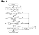
- Fig. 2 is a flowchart showing the process for orientation stabilizing control during braking according to a first embodiment;
- Fig. 3 is a flowchart showing the process for orientation stabilizing control during braking according to a second embodiment;
- Fig. 4 is a graph showing the manner for control for reducing the assist force according to the second embodiment;
- Fig. 5 is a flowchart showing the process for orientation stabilizing control during braking according to a first modification;
- Fig. 6 is a flowchart showing the process for orientation stabilizing control during braking according to a second modification;
- Fig. 7 is a flowchart showing the process for orientation stabilizing control during braking according to a third modification;
- Fig. 8 is a flowchart showing the process for orientation stabilizing control during braking according to a fourth modification;
- Fig. 9 is a diagram schematically showing the configuration of a torque sensor; and
- Fig. 10 is a diagram showing the relationship between the deflection of the orientation of a vehicle at the time of braking and self aligning torque.
- In the following, an electric power steering apparatus according to a first embodiment of the present invention will be described with reference to the drawings. Fig. 1 is a diagram schematically showing the configuration of the electric power steering apparatus (EPS) 1 according to the present embodiment. As shown in Fig. 1, a
steering shaft 3 to which asteering wheel 2 is secured is connected to arack 5 via a rack and pinion mechanism 4. Rotation of thesteering shaft 3 accompanying operation of thesteering wheel 2 is converted into linear reciprocation of therack 5 by means of the rack and pinion mechanism 4. This linear reciprocation of therack 5 changes the angle of the steeredwheels 6, that is to say, the steered angle, and thus, the direction in which the vehicle moves changes. - The
EPS 1 is provided with anEPS actuator 10, which is a steering force assisting device for providing assist force to assist operation of thesteering wheel 2 to the steering system, and an ECU 11, which is a control section for controlling the operation of thisEPS actuator 10. - The
EPS actuator 10 according to the present embodiment is a rack assist type EPS actuator, in which amotor 12, which is a drive source for the system, is coaxially placed with therack 5. The motor torque generated by themotor 12 is transmitted to therack 5 via a ball screw mechanism (not shown). Themotor 12 according to the present embodiment is a brushless motor which rotates when receiving supply of drive power in three phases (U, V and W) from the ECU 11. The ECU 11 controls operation of theEPS actuator 10, that is to say, assist force provided to the steering system, through the supply of drive power to themotor 12. - In detail, according to the present embodiment, a
torque sensor 14 is provided in the middle of thesteering shaft 3, which constitutes the steering transmission system between thesteering wheel 2 and the steeredwheels 6. Steering torque τ, which is detected by thistorque sensor 14, is inputted into the ECU 11. As thetorque sensor 14 according to the present embodiment, a publicly known twin resolver type torque sensor having the same configuration as thetorque sensor 23 shown in Fig. 9, that is to say, a torque sensor for detecting the steering torque τ on the basis of the torsion angle of thetorsion bar 22 provided in the middle of the steering shaft 3 (21) is used. Left and right wheel speeds V_L and V_R, which are detected bywheel speed sensors EPS actuator 10 in such a manner that assist force is generated in accordance with the steering torque τ and the vehicle speed V, concretely, assist force which is greater when (the absolute value of) the steering torque τ is greater and the vehicle speed V is lower is generated. - As described above, when the orientation of a vehicle having an EPS deflects at the time of braking, the driver restricts rotation of the steering wheel, and thus, assist force is provided in such a direction that the self aligning torque (SAT) which acts in such a direction as to stabilize the vehicle is cancelled. As a result, a problem arises, such that the vehicle drifts in the direction in which the vehicle deflects.
- The ECU 11 according to the present embodiment determines whether the orientation of the vehicle deflects at the time of braking. That is to say, the ECU 11 according to the present embodiment functions as a deflection sensing section. In addition, in the case where it is determined that the orientation of the vehicle is deflecting, the operation of the
EPS actuator 10 is controlled in order to reduce the assist force provided to the steering system. In the following description, this control is referred to as orientation stabilizing control during braking. - In detail, as shown in the flowchart of Fig. 2, the ECU 11 first acquires state quantities, which are used for the orientation stabilizing control during braking (Step 101). The steering angle θs detected by the
steering sensor 16 and the brake signal S_bk indicating whether a braking operation is being carried out, in addition to the above described steering torque τ, the vehicle speed V, and the left and right wheel speeds V_L and V_R, are inputted into the ECU 11 according to the present embodiment. - Next, the ECU 11 determines whether the vehicle is being braked on the basis of the brake signal S_bk (Step 102). In the case where the vehicle is being braked (YES in Step 102), the ECU 11 determines whether the absolute value of the steering angle θs is smaller than the predetermined threshold value θ0, in other words, whether the steering angle is within a predetermined angle range in the vicinity of neutral, that is to say, whether the brakes are being applied in a state where the vehicle is moving approximately straight forward (Step 103). In the case where the absolute value of the steering angle θs is smaller than the predetermined threshold value θ0 (YES in Step 103: |θs| < θ0), the ECU 11 determines whether the orientation of the vehicle is deflecting on the basis of the steering angle θs and the left and right wheel speeds V_L and V_R (Step 104). In the case where it is determined that the orientation of the vehicle is deflecting (YES in Step 104), control for reducing assist force generated by the
EPS actuator 10 is carried out (Step 105). - In the case where the conditions for determination in the above described
Steps 102 through 104 are not met, that is to say, in the case where it is determined that the brakes are not being applied (NO in Step 102), the absolute value of the steering angle θs is not smaller than the predetermined threshold value θ0 (NO in Step 103), or the orientation of the vehicle is not deflecting (NO in Step 104), the ECU 11 does not carry out the assist force reducing process inStep 105. In addition, the ECU 11 carries out normal control. That is to say, the ECU 11 controls the operation of theEPS actuator 10 in order to generate assist force in accordance with the steering torque τ and the vehicle speed V (Step 106). - The first embodiment has the following advantages.
- (1) The ECU 11 determines whether the orientation of the vehicle deflects at the time of braking. In addition, in the case where it is determined that the orientation of the vehicle is deflecting, the operation of the
EPS actuator 10 is controlled in order to reduce the assist force provided to the steering system. According to this configuration, the self aligning torque, which acts in such a direction as to stabilize the vehicle, can be effectively used when the vehicle is deflecting. As a result, it becomes possible to apply the brakes in a simple configuration in a state where the orientation of the vehicle is more stably maintained. - (2) The assist force when the vehicle is deflecting is reduced in the case where the absolute value of the steering angle θs is smaller than the predetermined threshold value θ0, in other words, in the case where the steering angle is within a predetermined angle range in the vicinity of neutral. That is to say, in some cases, the driver combines the steering operation and the braking operation so as to intentionally cause the orientation of the vehicle to deflect when turning. In this respect, the assist force can be reduced when the state of the vehicle is limited to one in which the vehicle moves straight forward in the above described configuration. Thus, the special cases described above can be excluded, and the orientation of the vehicle can be prevented with high precision from deflecting in a manner not intended by the driver.
- In the following, an EPS according to a second embodiment of the present invention will be described in reference to the drawings. The main difference between the present embodiment and the first embodiment is only in the manner for orientation stabilizing control during braking. Therefore, for the sake of convenience, in the description, the same symbols are attached to components which are the same as in the first embodiment, and description thereof is omitted.
- According to the present embodiment, an ECU 11 detects the vehicle speed V and forward/backward acceleration (longitudinal acceleration) G of the vehicle as a vehicle state quantity. In addition, in the case where the detected forward/backward acceleration G has a value which indicates deceleration which is greater than a predetermined value G1 (a negative value in the case where a value in the direction in which the vehicle moves is defined as a positive value, that is to say G ≤ -G1) and in the case where the vehicle speed V is greater than the predetermined speed V1, the operation of the
EPS actuator 10 is controlled in order to reduce the assist force provided to the steering system. - That is to say, in the case where the detected forward/rearward acceleration G has a value which indicates deceleration greater than the predetermined value G1 (for example -0.8 G), which is considered to be sudden application of the brakes causing deceleration no smaller than the predetermined deceleration, and if the vehicle speed V has a value indicating that the vehicle is running at high speed no less than the predetermined speed V1 (for example 100 km/h), the possibility of the orientation of the vehicle deflecting as described above is extremely high.
- The ECU 11, which is a deflection predicting section according to the present embodiment, predicts that the orientation of the vehicle will deflect in the case described above (G ≤ -G1 and V ≥ V1). In addition, the assist force provided to the steering system is reduced in advance, that is to say, control for reducing assistance is carried out, before the predicted deflection occurs. As a result, the self aligning torque (SAT) generated afterwards, that is to say, the SAT, which acts in such a direction as to stabilize the vehicle, is used effectively, so that the orientation of the vehicle is quickly stabilized.
- In detail, as shown in the flowchart of Fig. 3, when the ECU 11 acquires the state quantities (forward/backward acceleration G, vehicle speed V, steering torque τ, and steering speed ωs) used for orientation stabilizing control during braking (Step 201), it is first determined whether a reduction flag which indicates that control for reducing assistance should be carried out has already been set (Step 202). The steering angle speed ωs is acquired by time differentiating the steering angle θ. In the case where no reduction flag has been set (NO in Step 202), the ECU 11 predicts that the vehicle is in such a state that the orientation of the vehicle will easily deflect, that is to say, makes a determination and predicts that the vehicle will deflect (
Steps 203 and 204). - Concretely, the ECU 11 determines in the deflection prediction determination whether the forward/backward acceleration G has a value which indicates deceleration greater than the predetermined value G1 (Step 203), and whether the vehicle speed V is the predetermined speed V1 or higher (Step 204). In the case where the forward/backward acceleration G has a value indicating deceleration greater than the predetermined value G1 and the vehicle speed V is the predetermined speed V1 or higher (YES in
Step 203 and YES in Step 204: G ≤ -G1 and V ≥ V1), the ECU 11 predicts that the orientation of the vehicle will deflect, sets a reduction flag (Step 205), and carries out control for reducing the assistance (Step 206). - In the case where it is determined that the forward/backward acceleration G is not a value indicating deceleration greater than the predetermined value G1 in the above described Step 203 (NO in Step 203: G > -G1) or in the case where the vehicle speed V is lower than the predetermined speed V1 in the above described Step 204 (NO in Step 204: V < V1), the ECU 11 predicts that the orientation of the vehicle will not deflect. In addition, the ECU 11 carries out normal assist control without setting the reduction flag as described above. That is to say, the ECU 11 controls operation of the
EPS actuator 10 in order to generate assist force in accordance with the steering torque τ and the vehicle speed V (Step 207). - As shown in Fig. 4, the ECU 11 according to the present embodiment sets the assist force to "0" in the assistance reducing control in the case where (the absolute value of) the steering torque τ is within a range corresponding to the self aligning torque generated when the vehicle deflects, that is to say, is smaller than the upper limit value τ0 of the steering torque τ, which is detected as the self aligning torque (|τ| < τ0). In the drawing, the solid lines L indicate the assistance properties at the time of normal assist control, and the broken lines M indicate the assistance properties at the time of the assistance reducing control. In the region where the steering torque τ is this upper limit value τ0 or higher (|τ| ≥ τ0), the greater the steering torque τ is, the smaller the degree of reduction in the assist force provided to the steering system becomes.
- That is to say, in the case where it is predicted that the orientation of the vehicle will deflect, the assist force is set to "0," and thus, the self aligning torque, which acts in such a direction as to stabilize the vehicle, can be used effectively without being weakened by this assist force. In addition, in the case where the steering torque τ which exceeds the range corresponding to the self aligning torque generated when the vehicle deflects is detected, it is assumed that the driver is carrying out a certain steering operation. In such cases, the greater the steering torque τ is, the greater the provided assist force is (assist force close to that at the time of normal assist control), and thus, the steering operation is assisted without giving the driver a sense of discomfort.
- Meanwhile, in the case where it is determined that the reduction flag has already been set in the above described Step 202 (YES in Step 202), the ECU 11 subsequently determines whether the above described assistance reducing control should be canceled (
Steps 208 to 211). - Concretely, the ECU 11 determines whether the forward/backward acceleration G is a value indicating deceleration which is smaller than the deceleration indicated by the predetermined value G2 (Step 208), whether the vehicle speed V is the predetermined speed V2 or lower (Step 209), and whether (the absolute value of) the steering speed ωs is the predetermined speed ω1 or higher (Step 210) in this determination for canceling. The predetermined value G2 and the predetermined speed V2 are set in accordance with the lower limit value (for example -0.2 G and 80 km/h) in the region where it is predicted that the vehicle will easily deflect. The predetermined speed ω1 is set in accordance with the value where it is assumed that the driver has carried out a steering operation. In addition, in the case where it is determined that the forward/backward acceleration G is a value indicating deceleration which is smaller than the deceleration indicated by the predetermined value G2 (YES in Step 208: G ≥ -G2), the vehicle speed V is the predetermined speed V2 or lower (YES in Step 209: V ≤ V2), or the steering speed ωs is the predetermined speed ω1 or higher (YES in Step 210: |ωs| ≥ ω1), the ECU 11 subsequently determines whether (the absolute value of) the steering torque τ is the predetermined threshold value τ1 or lower (Step 211).
- In the case where it is determined that the steering torque τ is the predetermined threshold value τ1 or lower (YES in Step 211: |τ| ≤ τ1), the reduction flag is reset in order to cancel the above described assistance reducing control (Step 212), and normal assist control (Step 207) is carried out.
- In the above described
Step 211, the determination allows the manner for assist control to return from reduction control to normal control in a state where the steering torque τ is relatively small, and as a result, the steering feel can be prevented from changing together with the switching of this assist control. - In addition, in the case where it is determined that the forward/backward acceleration G is a value indicating deceleration which is greater than the deceleration indicated by the predetermined value G2 (G < -G2), the vehicle speed V is greater than the predetermined speed V2 (V > V2), and the steering speed ωs is smaller than the predetermined speed ω1 (|ωs| < ω1) in the above described
Steps 208 to 210 (NO in all ofsteps 208 to 210), or in the case where it is determined that the steering torque τ is greater than the predetermined threshold value τ1 in Step 211 (NO in Step 211: |τ| > τ1), the ECU 11 determines that the above described assistance reducing control should be continued. Thus, the above described reduction flag is not reset, and the assistance reducing control is carried out (Step 206). - The second embodiment has the following advantages.
- (1) The ECU 11 controls the operation of the
EPS actuator 10 in order to reduce the assist force provided to the steering system in the case where the detected forward/backward acceleration G has a value indicating deceleration greater than the predetermined value G1 (a negative value in the case where a value in the direction in which the vehicle moves is defined as a positive value, that is to say, G ≤ -G1) and in the case where the vehicle speed V is the predetermined speed V1 or higher.
That is to say, in the case where the detected forward/backward acceleration G has a value indicating deceleration greater than the predetermined value G1, which is considered to be sudden application of the brakes causing deceleration no smaller than the predetermined deceleration, and in the case where the vehicle speed V has a value indicating that the vehicle is running at a high speed no lower than the predetermined speed V1, the possibility of the orientation of the vehicle deflecting as described above is extremely high. Accordingly, as in the above described configuration, the orientation of the vehicle is predicted to deflect, and the assistance reducing control is carried out in advance before the predicted deflection takes place. Thus, the self aligning torque, which acts in such a direction as to stabilize the vehicle afterwards, can be effectively used. As a result, the orientation of the vehicle is stabilized more smoothly. - (2) The ECU 11 sets the assist force to "0" in the assistance reducing control in the case where (the absolute value of) the detected steering torque τ is within a range corresponding to the self aligning torque generated at the time of deflecting of the vehicle (|τ| < τ0). In addition, in the region where the steering torque τ is the upper limit value τ0 or higher (|τ| ≥ τ0), the greater this steering torque τ is, the smaller the degree of reduction in the assist force provided to the steering system becomes.
- In the above described configuration, in the case where it is predicted that the orientation of the vehicle will deflect, the assist force is set to "0," and thus, the self aligning torque, which acts in such a direction as to stabilize the vehicle, can be used effectively without being weakened by this assist force. In addition, in the case where the steering torque τ is detected when it is assumed that the driver is carrying out a certain steering operation, the greater this steering torque τ is, the greater the provided assist force becomes (assist force close to that at the time of normal assist control). Thus, the steering operation is assisted without giving the driver a feeling of discomfort.
- The configuration according to the above described embodiments may be modified as follows.
- According to the first embodiment, in the case where it is determined that the orientation of the vehicle is deflecting, the assist force provided to the steering system is simply reduced. However, it is preferable for an appropriate degree of reduction in the assist force to be set in accordance with the specifications of the vehicle. In addition, as shown in the flowchart of Fig. 5, a configuration for reducing the assist force to "0" (Step 305) may be adopted. In this configuration, the self aligning torque, which acts in such a direction as to stabilize the vehicle, can be used effectively without being weakened by the assist force. The process in
Steps 301 to 304 andStep 306 in the flowchart of Fig. 5 are the same as the process inSteps 101 to 104 andStep 106 in the flowchart of Fig. 2, and therefore, descriptions thereof are omitted. Furthermore, In the case where the detected steering torque τ is within a range corresponding to the self aligning torque generated when the vehicle deflects, as in the second embodiment, the configuration where the assist force is reduced to "0" may be adopted. - According to the first embodiment, the assist force when the vehicle deflects is reduced in the case where the absolute value of the steering angle θs is smaller than the predetermined threshold value θ0 (see Fig. 2, Step 103). However, this condition may be omitted. That is to say, the orientation of the vehicle sometimes deflects without the driver's intent at the time of braking during turning, and such cases can be dealt with by omitting the above described condition that the vehicle be moving straight forward.
- In addition, in the case where the assist force is reduced on the basis of the prediction that the vehicle will deflect, as in the second embodiment, determination that the vehicle is in such a state as to be moving straight forward may be adopted, as in the first embodiment. As shown in the flowchart of Fig. 6, for example, in the case where the orientation of the vehicle is predicted to deflect as a result of the prediction of deflection in
Steps 403 and 404 (YES inStep 403 and YES in Step 404: G ≤ -G1 and V ≥ V1), subsequently, it is determined whether (the absolute value of) the steering angle θs is smaller than the predetermined threshold value θ1 (Step 405). The determination of the steering angle conditions in thisStep 405 is determination that the vehicle is in such a state as to be moving straight forward, where it is determined the steering angle θs is within a predetermined angle range in the vicinity of neutral, that is to say, whether the brakes are being applied in such a state that the vehicle is moving approximately straight forward, in the same manner as the conditions for determining the steering angle according to the first embodiment (see Fig. 2, Step 103). In addition, in the case where it is determined that the steering angle θs is smaller than the predetermined threshold value θ1 (YES in Step 405: |θs| < θ1), a reduction flag is set (Step 406) and the assistance reducing control is carried out (Step 407). In the case where the condition for the steering angle is not met in this Step 405 (NO in Step 405: |θs| ≥ θ1), control for normal assistance (Step 408) may be carried out without setting the reduction flag. The assist force may be reduced when the state of the vehicle is limited to one where the vehicle is moving straight forward, as described above, and thus, the above described specific cases (for example intentional operation by the driver) can be excluded, and the orientation of the vehicle is prevented from deflecting in a manner not intended by the driver with high precision. - In addition, such steering angle condition may be added to the determination for canceling the assistance reducing control. That is to say, as shown in Fig. 6, determination of the steering angle condition (Step 412) is carried out subsequent to the determination of the acceleration (deceleration) condition, the determination of the speed condition, and the determination of steering speed condition (
Steps 409 to 411). In addition, also in the case where the steering angle θs is the predetermined threshold value θ1 or larger in the determination of the steering angle condition in Step 412 (YES in Step 412: |θs| ≥ θ1), the reduction flag is reset (Step 413). As a result, it becomes possible to assist this steering operation without giving the driver a feeling of discomfort by canceling the assistance reducing control in the case where the steering operation is being carried out by the driver, even during the assistance reducing control. - The processes in
Steps 401 to 404,Steps 406 to 408,Steps 409 to 411,Step 413 andStep 414 in the flowchart of Fig. 6 are the same as the processes inSteps 201 to 204,Steps 205 to 207,Steps 208 to 210,Step 211 andStep 212 in the flowchart of Fig. 3, respectively, and therefore, descriptions thereof are omitted. - Furthermore, determination of the steering speed condition as that shown in
Step 411 in Fig. 6 may be carried out so as to correspond to the determination of the conditions for commencing the assistance reducing control, which is carried out subsequently to the above described sensing of the change or prediction of deflection, that is to say, the determination of the steering angle condition shown inStep 405 in Fig. 6. That is to say, in the case where (the absolute value of) the steering speed ωs is the predetermined speed ω1 or higher (|ωs| ≥ ω1), it can be assumed that the driver is carrying out a steering operation. Accordingly, the above described determination of the steering speed condition is added, and thus, it becomes possible to assist the steering operation in an appropriate manner, without giving the driver a feeling of discomfort. - According to the first embodiment, the determination as to whether the orientation of the vehicle is deflecting (see Fig. 2, Step 104) is carried out on the basis of the steering angle θs and the left and right wheel speeds V_L and V_R. However, the manner for determination is not limited to this, and the above described determination, may be carried out in, for example, a vehicle having a yaw rate sensor, through detection of the actual yaw rate.
- Furthermore, the above described yaw rate condition and the wheel speed difference condition, for example, may be added to the prediction that the vehicle will deflect also in the case where the assist force is reduced on the basis of the prediction that the vehicle will deflect, as in the second embodiment. As shown in the flowchart of Fig. 7, for example, in the prediction that the vehicle will deflect, following the determination for the conditions for acceleration (or deceleration) (Step 503) and the determination of the speed condition (Step 504), it is determined whether (the absolute value of) the yaw rate γ is the predetermined threshold value γ1 or higher (Step 505). It is not necessary for the threshold value γ1, in terms of the yaw rate γ in this case, to be the same as the threshold value in the case where the yaw rate condition is added to the determination as to whether deflection is sensed according to the above described first embodiment, and the threshold value may be an appropriate value for this "prediction." In addition, in the case where it is determined that the yaw rate γ is the predetermined threshold value γ1 or higher (YES in Step 505: |γ| ≥ γ1), the determination of the state where the vehicle is moving straight forward (Step 506) is carried out on the basis of the steering angle θs, and in the case where the steering angle condition is met (YES in Step 506: |θs| < θ1), a reduction flag is set (Step 507) and control for reducing the assist is carried out (Step 508). In the case where it is determined that the yaw rate γ is smaller than the predetermined threshold value γ1 in Step 505 (NO in Step 505: |γ| < γ1), the above described determination of the state where the vehicle is moving straight forward (Step 506) is not carried out and the reduction flag (Step 507) is not set, but the normal assistance control is carried out (Step 508). In this configuration, deflection in the orientation of the vehicle can be predicted with higher precision.
- The processes in
Steps 501 to 504 andSteps 506 to 515 in the flowchart of Fig. 7 are the same as the processes inSteps 401 to 404 andSteps 405 to 414 in the flowchart of Fig. 6, respectively, and therefore, descriptions thereof are omitted. In addition, the determination of the yaw rate condition inStep 506 in Fig. 7 may be changed to determination of the wheel speed difference or determination of yaw angle acceleration. - According to the first embodiment, determination of braking (see Fig. 2, Step 102) is carried out on the basis of the brake signal S_bk. However, the invention is not limited to this, and the above described determination may be carried out on the basis of the acceleration (or deceleration) gained by differentiating the vehicle speed V.
- In addition, determination of braking in accordance with prediction that the vehicle will deflect may be carried out depending on whether a braking operation is being carried out also in the case where the assist force is reduced on the basis of the prediction that the vehicle will deflect, as in the second embodiment. Concretely, the process shown in the flowchart of Fig. 8, for example, may be adopted.
- That is to say, first, the vehicle speed V and the brake signal S_bk are acquired as the state quantities, which are used for the orientation stabilizing control during braking (Step 601). Next, it is determined whether a reduction flag is set (Step 602), and in the case where a reduction flag is not set (NO in Step 602), it is determined whether the brake signal S_bk is on (Step 603) and whether the vehicle speed V is the predetermined speed V1 or higher (Step 604). In addition, in the case where the brake signal S_bk is on and the vehicle speed V is the predetermined speed V1 or higher (YES in
Step 603 and YES in Step 604: S_bk is on and V ≥ V1), the orientation of the vehicle is predicted to deflect and the reduction flag is set (Step 605). Thus, the assistance reducing control is carried out (Step 606). In addition, in the case where it is determined that the brake signal S_bk is not on in the above described Step 603 (NO in Step 603: S_bk is off), or in the case where the vehicle speed V is lower than the predetermined speed V1 in the above described Step 604 (NO in Step 603: V < V1), the orientation of the vehicle is predicted not to deflect. Thus, the above described reduction flag is not set, and the normal assistance control is carried out (Step 607). - Meanwhile, in the case where it is determined that the reduction flag has already been set in the above described Step 602 (YES in Step 602), it is next determined whether the brake signal S_bk is off (Step 608) and whether the vehicle speed V is the predetermined speed V2 or lower (Step 609). Then, in the case where it is determined that the brake signal S_bk is off (YES in Step 608: S_bk is off), or the vehicle speed V is the predetermined speed V2 or lower (YES in Step 609: V ≤ V2), the reduction flag is reset in order to cancel the above described assistance reducing control (Step 610), and the normal assistance control is carried out (Step 607). In the case where the brake signal S_bk is not off (NO in Step 608: S_bk is on) and the vehicle speed V is greater than the predetermined speed V2 (NO in Step 609: V > V2) in the above described
Steps - According to the first embodiment, a case where the vehicle speed is the predetermined speed or higher or a case where the brakes are suddenly applied so that the deceleration is a predetermined deceleration or higher may be added as a condition for carrying out the assist force reducing control when the orientation of the vehicle deflects. That is to say, the orientation of the vehicle at the time of braking easily deflects when braking starts in a state where the vehicle is running at high speed or the brakes are suddenly applied. Accordingly, in the above described configurations, the orientation of the vehicle can be prevented from deflecting in a manner not intended by the driver with higher precision.
- The determinations of the conditions included in the determination for canceling the assistance reducing control may be changed as necessary. Although in the above described second embodiment, for example, the determination for canceling includes the steering torque condition (see Fig. 3, Step 211), it is not necessary to adopt a configuration including this.
- An ECU determines whether the orientation of the vehicle is deflecting at the time of braking. In addition, in a case where it is determined that the orientation of the vehicle is deflecting, the ECU controls operation of an EPS actuator in order to reduce the assist force provided to the steering system.
Claims (9)
- An electric power steering apparatus comprising a steering force assisting device for providing assist force for assisting steering operation to a steering system using a motor as a drive source, a torque sensor for detecting the steering torque on the basis of the torsion angle of a torsion bar provided in the middle of a steering transmission system connecting a steering wheel to a steered wheel, and a control section for controlling the assist force generated by the steering force assisting device on the basis of the detected steering torque, the apparatus being characterized by:a deflection sensing section for sensing deflection in the orientation of the vehicle,wherein the control section reduces the assist force generated by the steering force assisting device in a case where deflection is sensed at the time of braking of the vehicle.
- The electric power steering apparatus according to claim 1, characterized in that the control section reduces the assist force at the time of braking of the vehicle in a case where the vehicle speed is a predetermined speed or higher.
- An electric power steering apparatus comprising a steering force assisting device for providing assist force for assisting steering operation to a steering system using a motor as a drive source, a torque sensor for detecting the steering torque on the basis of the torsion angle of a torsion bar provided in the middle of a steering transmission system connecting a steering wheel to a steered wheel, and a control section for controlling the assist force generated by the steering force assisting device on the basis of the detected steering torque,
the apparatus being characterized in that the control section reduces the assist force generated by the steering force assisting device in a case where the vehicle speed is a predetermined speed or higher at the time of braking of the vehicle. - The electric power steering apparatus according to any of claims 1 to 3, characterized in that the control section reduces the assist force at the time of braking of the vehicle when brakes are suddenly applied so that the deceleration becomes a predetermined deceleration or higher.
- The electric power steering apparatus according to any of claims 1 to 4, characterized in that the control section reduces the assist force at the time of braking of the vehicle in a case where the steering angle of the steering wheel is within a predetermined angle range in the vicinity of neutral.
- The electric power steering apparatus according to any of claims 1 to 5, characterized in that the control section reduces the assist force at the time of braking of the vehicle in a case where the steering speed is a predetermined speed or lower.
- An electric power steering apparatus comprising a steering force assisting device for providing assist force for assisting steering operation to a steering system using a motor as a drive source, a torque sensor for detecting the steering torque on the basis of the torsion angle of a torsion bar provided in the middle of a steering transmission system connecting a steering wheel to a steered wheel, and a control section for controlling the assist force generated by the steering force assisting device on the basis of the detected steering torque, the apparatus being characterized by:a deflection predicting section for predicting deflection in the orientation of the vehicle at the time of braking of the vehicle,wherein the control section reduces the assist force generated by the steering force assisting device in a case where deflection is predicted.
- The electric power steering apparatus according to any of claims 1 to 7, characterized in that the control section reduces the assist force to zero.
- The electric power steering apparatus according to any of claims 1 to 7, characterized in that the control section reduces the assist force to zero in a case where the steering torque is within a range corresponding to the self aligning torque generated during deflection of the vehicle.
Applications Claiming Priority (2)
| Application Number | Priority Date | Filing Date | Title |
|---|---|---|---|
| JP2006261104 | 2006-09-26 | ||
| JP2007025537A JP5037156B2 (en) | 2006-09-26 | 2007-02-05 | Electric power steering device |
Publications (3)
| Publication Number | Publication Date |
|---|---|
| EP1905670A2 true EP1905670A2 (en) | 2008-04-02 |
| EP1905670A3 EP1905670A3 (en) | 2012-04-25 |
| EP1905670B1 EP1905670B1 (en) | 2014-05-14 |
Family
ID=38657247
Family Applications (1)
| Application Number | Title | Priority Date | Filing Date |
|---|---|---|---|
| EP07117174.8A Expired - Fee Related EP1905670B1 (en) | 2006-09-26 | 2007-09-25 | Electric power steering apparatus |
Country Status (4)
| Country | Link |
|---|---|
| US (1) | US7708109B2 (en) |
| EP (1) | EP1905670B1 (en) |
| JP (1) | JP5037156B2 (en) |
| CN (1) | CN101172488B (en) |
Cited By (3)
| Publication number | Priority date | Publication date | Assignee | Title |
|---|---|---|---|---|
| EP2239179A1 (en) | 2009-04-07 | 2010-10-13 | Honda Motor Co., Ltd. | Vehicle steering system |
| FR3076529A1 (en) * | 2018-01-10 | 2019-07-12 | Jtekt Europe | BRAKE PATH DEVIATION COMPENSATION METHOD WITH POWER-ASSISTED STEERING |
| CN111483514A (en) * | 2019-01-29 | 2020-08-04 | 操纵技术Ip控股公司 | Steering wheel fixation in steer-by-wire systems |
Families Citing this family (8)
| Publication number | Priority date | Publication date | Assignee | Title |
|---|---|---|---|---|
| JP5029312B2 (en) * | 2007-11-20 | 2012-09-19 | 株式会社ジェイテクト | Electric power steering device |
| US8116945B2 (en) * | 2008-01-16 | 2012-02-14 | Jtekt Corporation | Electric power steering device |
| JP5157517B2 (en) * | 2008-01-21 | 2013-03-06 | 株式会社ジェイテクト | Electric power steering device |
| US8594880B2 (en) | 2008-04-24 | 2013-11-26 | Honda Motor Co., Ltd. | Vehicle body flow suppression device |
| JP2009269540A (en) | 2008-05-09 | 2009-11-19 | Jtekt Corp | Electric power steering device |
| JP5521954B2 (en) * | 2010-09-29 | 2014-06-18 | 株式会社ジェイテクト | Electric power steering device |
| JP6024656B2 (en) * | 2011-06-15 | 2016-11-16 | 株式会社ジェイテクト | Electric power steering device |
| KR102274126B1 (en) | 2017-04-19 | 2021-07-07 | 현대자동차주식회사 | Control apparatus and method of motor driven power steering system |
Citations (3)
| Publication number | Priority date | Publication date | Assignee | Title |
|---|---|---|---|---|
| WO2002074638A1 (en) | 2001-03-20 | 2002-09-26 | Lucas Industries Limited | Steering control during split-mu abs braking |
| FR2835232A1 (en) | 2002-01-31 | 2003-08-01 | Koyo Seiko Co | SELF-ALIGNING TORQUE CORRECTION DEVICE FOR A VEHICLE AND ELECTRICAL ASSISTED STEERING DEVICE |
| US20050205346A1 (en) | 2004-03-02 | 2005-09-22 | Hiroaki Aizawa | Steering control apparatus for a vehicle |
Family Cites Families (21)
| Publication number | Priority date | Publication date | Assignee | Title |
|---|---|---|---|---|
| JPH0815865B2 (en) * | 1986-09-24 | 1996-02-21 | スズキ株式会社 | Power steering device |
| JPH06312666A (en) | 1993-04-29 | 1994-11-08 | Suzuki Motor Corp | Power steering device |
| US5580694A (en) | 1994-06-27 | 1996-12-03 | International Business Machines Corporation | Photoresist composition with androstane and process for its use |
| JP3390333B2 (en) * | 1997-08-27 | 2003-03-24 | 本田技研工業株式会社 | Electric power steering device |
| JPH11334633A (en) * | 1998-05-22 | 1999-12-07 | Koyo Seiko Co Ltd | Power steering system |
| JP2000104219A (en) | 1998-09-28 | 2000-04-11 | Nkk Corp | Erection of combined truss bridge |
| JP2001088723A (en) * | 1999-09-28 | 2001-04-03 | Mazda Motor Corp | Steering device for vehicle |
| JP2002104219A (en) | 2000-09-27 | 2002-04-10 | Toyoda Mach Works Ltd | Control device of motor-driven power steering device |
| US6845309B2 (en) * | 2002-01-30 | 2005-01-18 | Visteon Global Technologies, Inc. | Electric power assist torque check |
| EP1348610B1 (en) * | 2002-03-29 | 2008-01-30 | Jtekt Corporation | Vehicle control device with power steering device |
| JP3908074B2 (en) * | 2002-04-08 | 2007-04-25 | アイシン精機株式会社 | Electric steering control device and vehicle anti-skid control device having the same |
| JP2004009857A (en) * | 2002-06-05 | 2004-01-15 | Mitsubishi Motors Corp | Steering control device for vehicle |
| JP3780985B2 (en) * | 2002-07-26 | 2006-05-31 | トヨタ自動車株式会社 | Steering control device for vehicle |
| US6968261B2 (en) * | 2003-01-03 | 2005-11-22 | General Motors Corporation | Method and apparatus for vehicle stability enhancement system |
| US6804594B1 (en) * | 2003-03-28 | 2004-10-12 | Delphi Technologies, Inc. | Active steering for handling/stability enhancement |
| JP2006117181A (en) * | 2004-10-25 | 2006-05-11 | Favess Co Ltd | Steering control device |
| JP4424181B2 (en) * | 2004-12-03 | 2010-03-03 | 日産自動車株式会社 | Vehicle steering control device |
| JP4626290B2 (en) * | 2004-12-14 | 2011-02-02 | 日産自動車株式会社 | Vehicle deflection suppression device |
| JP4457911B2 (en) * | 2005-02-14 | 2010-04-28 | トヨタ自動車株式会社 | Power steering control device |
| JP4628819B2 (en) * | 2005-02-22 | 2011-02-09 | 本田技研工業株式会社 | Reaction force control method |
| DE102005049368B4 (en) * | 2005-10-11 | 2017-06-08 | Volkswagen Ag | Method and device for braking a two-lane motor vehicle at different friction conditions of the vehicle lanes |
-
2007
- 2007-02-05 JP JP2007025537A patent/JP5037156B2/en not_active Expired - Fee Related
- 2007-09-24 US US11/860,058 patent/US7708109B2/en not_active Expired - Fee Related
- 2007-09-25 EP EP07117174.8A patent/EP1905670B1/en not_active Expired - Fee Related
- 2007-09-25 CN CN2007101518639A patent/CN101172488B/en not_active Expired - Fee Related
Patent Citations (3)
| Publication number | Priority date | Publication date | Assignee | Title |
|---|---|---|---|---|
| WO2002074638A1 (en) | 2001-03-20 | 2002-09-26 | Lucas Industries Limited | Steering control during split-mu abs braking |
| FR2835232A1 (en) | 2002-01-31 | 2003-08-01 | Koyo Seiko Co | SELF-ALIGNING TORQUE CORRECTION DEVICE FOR A VEHICLE AND ELECTRICAL ASSISTED STEERING DEVICE |
| US20050205346A1 (en) | 2004-03-02 | 2005-09-22 | Hiroaki Aizawa | Steering control apparatus for a vehicle |
Cited By (7)
| Publication number | Priority date | Publication date | Assignee | Title |
|---|---|---|---|---|
| EP2239179A1 (en) | 2009-04-07 | 2010-10-13 | Honda Motor Co., Ltd. | Vehicle steering system |
| US8267219B2 (en) | 2009-04-07 | 2012-09-18 | Honda Motor Co., Ltd | Vehicle steering system |
| FR3076529A1 (en) * | 2018-01-10 | 2019-07-12 | Jtekt Europe | BRAKE PATH DEVIATION COMPENSATION METHOD WITH POWER-ASSISTED STEERING |
| WO2019138178A1 (en) * | 2018-01-10 | 2019-07-18 | Jtekt Europe | Method for compensating for trajectory deviation when braking with power steering |
| US11383763B2 (en) | 2018-01-10 | 2022-07-12 | Jtekt Europe | Method for compensating for trajectory deviation when braking with power steering |
| CN111483514A (en) * | 2019-01-29 | 2020-08-04 | 操纵技术Ip控股公司 | Steering wheel fixation in steer-by-wire systems |
| US11254345B2 (en) | 2019-01-29 | 2022-02-22 | Steering Solutions Ip Holding Corporation | Securing steering wheel in steer-by-wire systems |
Also Published As
| Publication number | Publication date |
|---|---|
| JP5037156B2 (en) | 2012-09-26 |
| CN101172488B (en) | 2010-12-08 |
| EP1905670B1 (en) | 2014-05-14 |
| JP2008105657A (en) | 2008-05-08 |
| CN101172488A (en) | 2008-05-07 |
| US20080217096A1 (en) | 2008-09-11 |
| US7708109B2 (en) | 2010-05-04 |
| EP1905670A3 (en) | 2012-04-25 |
Similar Documents
| Publication | Publication Date | Title |
|---|---|---|
| EP1905670B1 (en) | Electric power steering apparatus | |
| CN109963766B (en) | Control steer-by-wire type steering system | |
| EP1577194B1 (en) | Steering apparatus for vehicle and method for controlling the same | |
| CN107848573B (en) | Control device for power steering device and power steering device | |
| EP1621448B1 (en) | Vehicle steering control system | |
| EP1731408B1 (en) | Vehicle steering apparatus | |
| CN100418829C (en) | Steering system and method for automotive vehicle | |
| JP4924378B2 (en) | Vehicle travel control device | |
| US6886656B2 (en) | Electric power steering apparatus | |
| US7383111B2 (en) | Steering apparatus | |
| US11247715B2 (en) | Steer-by-wire system, motor vehicle, and method for operating a steer-by-wire system | |
| CN113661113B (en) | Method for controlling a steer-by-wire system and steer-by-wire system for a motor vehicle | |
| CN111591341B (en) | Electric power steering apparatus | |
| WO2012005107A1 (en) | Vehicle steering device | |
| EP1700773B1 (en) | Variable steering ratio system and steering method | |
| US8838339B2 (en) | Method for determining a torque on a steering train | |
| US20110218708A1 (en) | Power steering device | |
| US7677352B2 (en) | Method for steering a vehicle by means of a superimposed steering system | |
| WO2012002179A1 (en) | Vehicle steering device | |
| CN114312983A (en) | Steering control device | |
| JP2004168150A (en) | Electronic steering device | |
| JP2007283954A (en) | Steering device | |
| JP2005059645A (en) | Winker cancel device in steer-by-wire type steering device | |
| US8005593B2 (en) | Method for determining a torque on a steering train of a vehicle with dynamic drive system | |
| JP4062754B2 (en) | vehicle |
Legal Events
| Date | Code | Title | Description |
|---|---|---|---|
| PUAI | Public reference made under article 153(3) epc to a published international application that has entered the european phase |
Free format text: ORIGINAL CODE: 0009012 |
|
| AK | Designated contracting states |
Kind code of ref document: A2 Designated state(s): AT BE BG CH CY CZ DE DK EE ES FI FR GB GR HU IE IS IT LI LT LU LV MC MT NL PL PT RO SE SI SK TR |
|
| AX | Request for extension of the european patent |
Extension state: AL BA HR MK YU |
|
| PUAL | Search report despatched |
Free format text: ORIGINAL CODE: 0009013 |
|
| AK | Designated contracting states |
Kind code of ref document: A3 Designated state(s): AT BE BG CH CY CZ DE DK EE ES FI FR GB GR HU IE IS IT LI LT LU LV MC MT NL PL PT RO SE SI SK TR |
|
| AX | Request for extension of the european patent |
Extension state: AL BA HR MK RS |
|
| RIC1 | Information provided on ipc code assigned before grant |
Ipc: B62D 15/02 20060101ALI20120320BHEP Ipc: B62D 5/04 20060101AFI20120320BHEP |
|
| 17P | Request for examination filed |
Effective date: 20121004 |
|
| AKX | Designation fees paid |
Designated state(s): DE FR |
|
| RAP1 | Party data changed (applicant data changed or rights of an application transferred) |
Owner name: JTEKT CORPORATION Owner name: TOYOTA JIDOSHA KABUSHIKI KAISHA |
|
| 17Q | First examination report despatched |
Effective date: 20130214 |
|
| GRAP | Despatch of communication of intention to grant a patent |
Free format text: ORIGINAL CODE: EPIDOSNIGR1 |
|
| INTG | Intention to grant announced |
Effective date: 20140117 |
|
| GRAS | Grant fee paid |
Free format text: ORIGINAL CODE: EPIDOSNIGR3 |
|
| GRAA | (expected) grant |
Free format text: ORIGINAL CODE: 0009210 |
|
| AK | Designated contracting states |
Kind code of ref document: B1 Designated state(s): DE FR |
|
| RIN1 | Information on inventor provided before grant (corrected) |
Inventor name: SUZUKI, HIROSHI Inventor name: NISHIMURA, KENJI Inventor name: EKI, HIROZUMI Inventor name: TAMAIZUMI, TERUTAKA |
|
| REG | Reference to a national code |
Ref country code: DE Ref legal event code: R096 Ref document number: 602007036671 Country of ref document: DE Effective date: 20140618 |
|
| REG | Reference to a national code |
Ref country code: DE Ref legal event code: R097 Ref document number: 602007036671 Country of ref document: DE |
|
| PLBE | No opposition filed within time limit |
Free format text: ORIGINAL CODE: 0009261 |
|
| STAA | Information on the status of an ep patent application or granted ep patent |
Free format text: STATUS: NO OPPOSITION FILED WITHIN TIME LIMIT |
|
| 26N | No opposition filed |
Effective date: 20150217 |
|
| REG | Reference to a national code |
Ref country code: DE Ref legal event code: R097 Ref document number: 602007036671 Country of ref document: DE Effective date: 20150217 |
|
| REG | Reference to a national code |
Ref country code: FR Ref legal event code: PLFP Year of fee payment: 10 |
|
| REG | Reference to a national code |
Ref country code: FR Ref legal event code: PLFP Year of fee payment: 11 |
|
| REG | Reference to a national code |
Ref country code: FR Ref legal event code: PLFP Year of fee payment: 12 |
|
| PGFP | Annual fee paid to national office [announced via postgrant information from national office to epo] |
Ref country code: DE Payment date: 20200916 Year of fee payment: 14 Ref country code: FR Payment date: 20200812 Year of fee payment: 14 |
|
| REG | Reference to a national code |
Ref country code: DE Ref legal event code: R119 Ref document number: 602007036671 Country of ref document: DE |
|
| PG25 | Lapsed in a contracting state [announced via postgrant information from national office to epo] |
Ref country code: FR Free format text: LAPSE BECAUSE OF NON-PAYMENT OF DUE FEES Effective date: 20210930 Ref country code: DE Free format text: LAPSE BECAUSE OF NON-PAYMENT OF DUE FEES Effective date: 20220401 |