EP1905650A2 - An interior structure of vehicle equipped with curtain airbag - Google Patents
An interior structure of vehicle equipped with curtain airbag Download PDFInfo
- Publication number
- EP1905650A2 EP1905650A2 EP07018382A EP07018382A EP1905650A2 EP 1905650 A2 EP1905650 A2 EP 1905650A2 EP 07018382 A EP07018382 A EP 07018382A EP 07018382 A EP07018382 A EP 07018382A EP 1905650 A2 EP1905650 A2 EP 1905650A2
- Authority
- EP
- European Patent Office
- Prior art keywords
- curtain airbag
- pillar
- vehicle
- seatbelt anchor
- seatbelt
- Prior art date
- Legal status (The legal status is an assumption and is not a legal conclusion. Google has not performed a legal analysis and makes no representation as to the accuracy of the status listed.)
- Granted
Links
Images


Classifications
-
- B—PERFORMING OPERATIONS; TRANSPORTING
- B60—VEHICLES IN GENERAL
- B60R—VEHICLES, VEHICLE FITTINGS, OR VEHICLE PARTS, NOT OTHERWISE PROVIDED FOR
- B60R22/00—Safety belts or body harnesses in vehicles
- B60R22/18—Anchoring devices
- B60R22/24—Anchoring devices secured to the side, door, or roof of the vehicle
-
- B—PERFORMING OPERATIONS; TRANSPORTING
- B60—VEHICLES IN GENERAL
- B60R—VEHICLES, VEHICLE FITTINGS, OR VEHICLE PARTS, NOT OTHERWISE PROVIDED FOR
- B60R21/00—Arrangements or fittings on vehicles for protecting or preventing injuries to occupants or pedestrians in case of accidents or other traffic risks
- B60R21/02—Occupant safety arrangements or fittings, e.g. crash pads
- B60R21/16—Inflatable occupant restraints or confinements designed to inflate upon impact or impending impact, e.g. air bags
- B60R21/23—Inflatable members
- B60R21/231—Inflatable members characterised by their shape, construction or spatial configuration
- B60R21/2334—Expansion control features
- B60R21/2338—Tethers
-
- B—PERFORMING OPERATIONS; TRANSPORTING
- B60—VEHICLES IN GENERAL
- B60R—VEHICLES, VEHICLE FITTINGS, OR VEHICLE PARTS, NOT OTHERWISE PROVIDED FOR
- B60R13/00—Elements for body-finishing, identifying, or decorating; Arrangements or adaptations for advertising purposes
- B60R13/02—Internal Trim mouldings ; Internal Ledges; Wall liners for passenger compartments; Roof liners
- B60R13/0237—Side or rear panels
- B60R13/0243—Doors
-
- B—PERFORMING OPERATIONS; TRANSPORTING
- B60—VEHICLES IN GENERAL
- B60R—VEHICLES, VEHICLE FITTINGS, OR VEHICLE PARTS, NOT OTHERWISE PROVIDED FOR
- B60R13/00—Elements for body-finishing, identifying, or decorating; Arrangements or adaptations for advertising purposes
- B60R13/02—Internal Trim mouldings ; Internal Ledges; Wall liners for passenger compartments; Roof liners
- B60R13/0237—Side or rear panels
- B60R13/025—Pillars; Roof rails
-
- B—PERFORMING OPERATIONS; TRANSPORTING
- B60—VEHICLES IN GENERAL
- B60R—VEHICLES, VEHICLE FITTINGS, OR VEHICLE PARTS, NOT OTHERWISE PROVIDED FOR
- B60R13/00—Elements for body-finishing, identifying, or decorating; Arrangements or adaptations for advertising purposes
- B60R13/02—Internal Trim mouldings ; Internal Ledges; Wall liners for passenger compartments; Roof liners
- B60R2013/0287—Internal Trim mouldings ; Internal Ledges; Wall liners for passenger compartments; Roof liners integrating other functions or accessories
-
- B—PERFORMING OPERATIONS; TRANSPORTING
- B60—VEHICLES IN GENERAL
- B60R—VEHICLES, VEHICLE FITTINGS, OR VEHICLE PARTS, NOT OTHERWISE PROVIDED FOR
- B60R21/00—Arrangements or fittings on vehicles for protecting or preventing injuries to occupants or pedestrians in case of accidents or other traffic risks
- B60R21/02—Occupant safety arrangements or fittings, e.g. crash pads
- B60R21/16—Inflatable occupant restraints or confinements designed to inflate upon impact or impending impact, e.g. air bags
- B60R2021/161—Inflatable occupant restraints or confinements designed to inflate upon impact or impending impact, e.g. air bags characterised by additional means for controlling deployment trajectory
-
- B—PERFORMING OPERATIONS; TRANSPORTING
- B60—VEHICLES IN GENERAL
- B60R—VEHICLES, VEHICLE FITTINGS, OR VEHICLE PARTS, NOT OTHERWISE PROVIDED FOR
- B60R21/00—Arrangements or fittings on vehicles for protecting or preventing injuries to occupants or pedestrians in case of accidents or other traffic risks
- B60R21/02—Occupant safety arrangements or fittings, e.g. crash pads
- B60R21/16—Inflatable occupant restraints or confinements designed to inflate upon impact or impending impact, e.g. air bags
- B60R21/20—Arrangements for storing inflatable members in their non-use or deflated condition; Arrangement or mounting of air bag modules or components
- B60R21/215—Arrangements for storing inflatable members in their non-use or deflated condition; Arrangement or mounting of air bag modules or components characterised by the covers for the inflatable member
- B60R2021/21537—Arrangements for storing inflatable members in their non-use or deflated condition; Arrangement or mounting of air bag modules or components characterised by the covers for the inflatable member characterised by hinges
-
- B—PERFORMING OPERATIONS; TRANSPORTING
- B60—VEHICLES IN GENERAL
- B60R—VEHICLES, VEHICLE FITTINGS, OR VEHICLE PARTS, NOT OTHERWISE PROVIDED FOR
- B60R21/00—Arrangements or fittings on vehicles for protecting or preventing injuries to occupants or pedestrians in case of accidents or other traffic risks
- B60R21/02—Occupant safety arrangements or fittings, e.g. crash pads
- B60R21/16—Inflatable occupant restraints or confinements designed to inflate upon impact or impending impact, e.g. air bags
- B60R21/23—Inflatable members
- B60R21/231—Inflatable members characterised by their shape, construction or spatial configuration
- B60R21/2334—Expansion control features
- B60R21/2338—Tethers
- B60R2021/23386—External tether means
-
- B—PERFORMING OPERATIONS; TRANSPORTING
- B60—VEHICLES IN GENERAL
- B60R—VEHICLES, VEHICLE FITTINGS, OR VEHICLE PARTS, NOT OTHERWISE PROVIDED FOR
- B60R22/00—Safety belts or body harnesses in vehicles
- B60R22/18—Anchoring devices
- B60R2022/1818—Belt guides
-
- B—PERFORMING OPERATIONS; TRANSPORTING
- B60—VEHICLES IN GENERAL
- B60R—VEHICLES, VEHICLE FITTINGS, OR VEHICLE PARTS, NOT OTHERWISE PROVIDED FOR
- B60R21/00—Arrangements or fittings on vehicles for protecting or preventing injuries to occupants or pedestrians in case of accidents or other traffic risks
- B60R21/02—Occupant safety arrangements or fittings, e.g. crash pads
- B60R21/16—Inflatable occupant restraints or confinements designed to inflate upon impact or impending impact, e.g. air bags
- B60R21/20—Arrangements for storing inflatable members in their non-use or deflated condition; Arrangement or mounting of air bag modules or components
- B60R21/213—Arrangements for storing inflatable members in their non-use or deflated condition; Arrangement or mounting of air bag modules or components in vehicle roof frames or pillars
-
- B—PERFORMING OPERATIONS; TRANSPORTING
- B60—VEHICLES IN GENERAL
- B60R—VEHICLES, VEHICLE FITTINGS, OR VEHICLE PARTS, NOT OTHERWISE PROVIDED FOR
- B60R21/00—Arrangements or fittings on vehicles for protecting or preventing injuries to occupants or pedestrians in case of accidents or other traffic risks
- B60R21/02—Occupant safety arrangements or fittings, e.g. crash pads
- B60R21/16—Inflatable occupant restraints or confinements designed to inflate upon impact or impending impact, e.g. air bags
- B60R21/23—Inflatable members
- B60R21/231—Inflatable members characterised by their shape, construction or spatial configuration
- B60R21/232—Curtain-type airbags deploying mainly in a vertical direction from their top edge
Definitions
- the present invention relates to an interior structure of a vehicle equipped with a curtain airbag.
- Automotive vehicles are generally equipped with an airbag device to protect a passenger against a vehicle crash, turnover or the like.
- a curtain bag is known as an airbag of the airbag device, which inflates longitudinally so as to cover an inner face of a side window portion that comprises plural side window glasses, pillars and so on.
- a seatbelt anchor may be provided at the inner face of the pillar to be covered by the curtain airbag.
- US Patent No. 6,361,069 B1 discloses a structure in which the seatbelt anchor is provided so as to project inside from the center pillar trim that forms the inner face of the center pillar.
- the projecting potion is provided at a specified portion of the center pillar trim above the seatbelt anchor, which restrains the curtain airbag inflating from catching on the seatbelt anchor.
- US Patent Application Publication No. 2004/0150198 A1 discloses a structure in which the curtain airbag is provided inside not only the ceiling but the rear pillar.
- the curtain airbag is configured to inflate out of the gap between the front edge portion of the rear pillar trim and the side window glass, which is generated by pressing the front edge portion of the rear pillar inward by the curtain airbag.
- the rear pillar trim is generally made of synthetic resin that is harder than a material of the roof trim that forms an inner face of the ceiling. This is because the rear pillar trim may not be hurt improperly by a loaded baggage or the like.
- the curtain airbag be configured to provide a tension that extends longitudinally when its inflation is complete, for example, in order to improve the passenger's protection at the vehicle turnover or the like. Also, it may be considered that inflation gas is supplied to the curtain airbag from a specified location in front of the center pillar in order to secure the proper protection of passengers seated in the front seats.
- the provision of the tension extending longitudinally may cause the following problem. Namely, while the above-described gap is located outward from the inner face of the center pillar in a general vehicle structure, the curtain airbag inflates downward contacting the inner face of the center pillar when the inflation gas is supplied to the curtain airbag from the specified location in front of the center pillar (see FIG. 15). Accordingly, there is a concern that the curtain airbag may catch on the seatbelt anchor during its inflation.
- the present invention has been devised in view of the above-described problem, and an object of the present invention is to provide an interior structure of a vehicle equipped with a curtain airbag that can properly prevent the curtain airbag from catching on the seatbelt anchor particularly even if the curtain airbag inflates downward contacting the inner face of the center pillar during its inflation.
- an interior structure of a vehicle equipped with a curtain airbag comprising a roof trim at least partly forming a ceiling, a rear pillar trim forming an inner face of a rear pillar that is located at a rear portion of the vehicle, the rear pillar trim being made of a material, preferably of synthetic resin, that is harder than a material making the roof trim, a seatbelt anchor provided at an inner face of a center or intermediate pillar of the vehicle that is located in front of the rear pillar, the seatbelt anchor projecting inside of the vehicle, and a curtain airbag provided inside a side edge portion of the roof trim and the rear pillar trim along at least from an upper front portion of the center or intermediate pillar to the rear pillar, preferably to a lower portion of the rear pillar, the curtain airbag being configured to inflate at least partly covering at least an inner face of a side window portion of the vehicle that is located in front of a front edge portion of the rear pillar including the center or intermediate pillar, when inflatable or
- At least one slant or oblique face at an upper portion of the seatbelt anchor the slant face being formed in such a manner that a lower portion thereof is located inward.
- the seatbelt anchor is provided at the inner face of the center or intermediate pillar so as to rotate or pivot around an axis that extends substantially in a vehicle width direction, and the slant face is provided at or near the upper portion of the seatbelt anchor in such a manner that a clear rearview from a driver's seat is not substantially deteriorated by the seatbelt anchor rotating or pivoting by a specified (predetermined or predeterminable) rotational or pivotal angle for application of a seatbelt to a passenger.
- a properly clear rearview from the driver's seat can be obtained.
- the center or intermediate pillar comprises a center or intermediate pillar body and a center or intermediate pillar trim that at least partly covers the center or intermediate pillar body and form an inner face of the center or intermediate pillar
- the center or intermediate pillar is formed in such a manner that a central or intermediate portion thereof projects toward inside of the vehicle, and a gap in a vehicle width direction between an inner face of the center or intermediate pillar trim and a face of the seatbelt anchor that faces the inner face of the center or intermediate pillar trim preferably when the seatbelt anchor rotates or pivots due to the application of the seatbelt is configured not to become larger than the gap at the time of an non-application of the seatbelt.
- the curtain airbag is configured in such a manner that the inflatable or inflation gas is supplied thereto from a specified (predetermined or predeterminable) location in front of the center or intermediate pillar, the seatbelt anchor is configured such that an incline of the upper portion thereof is gentler than that of a front portion thereof, the seatbelt anchor is provided so as to rotate or pivot around an axis that extends substantially in a vehicle width direction, and there is provided a seatbelt holding member to hold the seatbelt anchor at a specified (predetermined or predeterminable) rotational or pivotal position such that a vertical direction of the seatbelt anchor has a specified (predetermined or predeterminable) angle or less relative to an inflation direction of the curtain airbag when the seatbelt is not applied.
- the curtain airbag inflates, the lower end of the curtain airbag contacts and slides down substantially on the inner face of the seatbelt anchor, so that the airbag can be properly prevented from catching on the seatbelt anchor.
- the inner face of the center or intermediate pillar has an uneven portion that is formed near an upper edge portion of the seatbelt anchor so as to overhang in such a manner that an upper overhanging or undercut portion is located inward from an outside end portion of the upper edge portion of the seatbelt anchor.
- the gap between the seatbelt anchor and the inner face of the center or intermediate pillar is at least partly hidden behind the upper-overhanging or undercut portion of the uneven portion, when viewed from above. Accordingly, it becomes difficult for the curtain airbag to get into the gap, so that the airbag can be further properly prevented from catching on the seatbelt anchor.
- the uneven portion is not necessary to be formed at an entire length of the center or intermediate pillar.
- the uneven portion of the center or intermediate pillar may be formed so as to located at least at a rear part of the center or intermediate pillar. This can provide the above-described effect as well.
- the curtain airbag is configured in such a manner that the inflatable or inflation gas is supplied thereto from a specified (predetermined or predeterminable) location in front of the center or intermediate pillar, there is provided an additional center or intermediate pillar in front of the center or intermediate pillar, and at an inner face of the additional center or intermediate pillar is provided an interior member (a seatbelt anchor, for example) to project inward of the vehicle.
- a seatbelt anchor for example
- the interior member (the seatbelt anchor, for example) is provided below a line that interconnects an upper end of the rear pillar trim and a front-end fixing portion of the curtain airbag and above a line that interconnects a rear end of the uneven portion and the front-end fixing portion of the curtain airbag.
- the curtain airbag is configured in such a manner that the inflatable or inflation gas is supplied thereto from a specified (predetermined or predeterminable) location in front of the center or intermediate pillar, and a rear end of the uneven portion is positioned at substantially the same height level as or below a front portion of the uneven portion that is located above the seatbelt anchor.
- the seatbelt anchor is located above a tension line that is generated at the curtain airbag so as to extend substantially in a vehicle longitudinal direction when the curtain airbag is in a specified (predetermined or predeterminable) inflation state.
- the curtain airbag provides a specified (predetermined or predeterminable) tension on a line that interconnects a specified (predetermined or predeterminable) portion of a lower edge portion of the airbag that is located below a gas inlet and an upper end portion of the rear pillar trim when the curtain airbag is in a specified (predetermined or predeterminable) inflation state, and the seatbelt anchor is located above the line of the specified (predetermined or predeterminable) tension.
- a front end portion of the curtain airbag is fixed to a vehicle body at a point below an upper end portion of the rear pillar trim
- the curtain airbag provides a specified (predetermined or predeterminable) tension on a line that interconnects the fixing point and an upper end portion of the rear pillar trim when the curtain airbag is in a specified (predetermined or predeterminable) inflation state
- the seatbelt anchor is located above the line of the specified (predetermined or predeterminable) tension.
- the tension at the initial stage of the inflation of the curtain airbag can be made properly small, so that the catching prevention effect of the curtain airbag can be surely obtained.
- the curtain airbag is configured to inflate with a first pressing force against a specified (predetermined or predeterminable) upper portion of the inner face of the center or intermediate pillar when the curtain airbag inflates pressing outward the roof trim in front of an upper end portion of the rear pillar trim and inflate with a second pressing force against a portion below the specified (predetermined or predeterminable) upper portion of the inner face of the center or intermediate pillar when the curtain airbag inflates downward from the upper end portion of the rear pillar trim, the second pressing force being greater than the first pressing force, and the seatbelt anchor is located at the specified (predetermined or predeterminable) upper portion of the inner face of the center or intermediate pillar.
- the curtain airbag may not catch on the seatbelt anchor even if it inflates contacting the inner face of the center or intermediate pillar.
- the proper inflation of the curtain airbag can be provided.
- a vehicle 1 comprises a front seat 2, a second row seat 3 that is provided behind the front seat 2, and a third row seat 4 that is provided behind the second row seat 3, as shown in FIG. 1.
- the vehicle 1 comprises a side door 5 for the front seat 2 and a side door 6 for the second row seat 3, and it also comprises an A pillar 7 (front pillar or post), one or more intermediate pillars or posts (specifically a B pillar 8, a C pillar 9 ) and a D pillar 10 (rear pillar or post), which are disposed from the front in order.
- the C pillar 9 preferably corresponds to a "center pillar” or “intermediate pillar”
- the D pillar preferably corresponds to a "rear pillar”.
- a rear side opening 15 is formed between the C pillar 9 and the D pillar 10, which is at least partly covered by a side window glass 16.
- the side window glasses 15, 16, the pillars 9, 10 and peripheral portions of these correspond to a preferred "side window portion".
- the three side window glasses 12, 14, 16 are configured to be covered at least partly, preferably substantially entirely by a curtain airbag 17 from the inside when a vehicle side crash or a vehicle turnover occur or these are predicted, for example.
- the curtain airbag 17 preferably is folded or collapsed (in a regular and/or irregular manner) in a single bar shape in its folded state, which is fixed or fixable to a vehicle body substantially along or near edge portions of the window glasses 12, 14, 16.
- a front end portion of the curtain airbag 17 is fixed to (preferably a lower portion of) the A pillar 7, its rear end portion is fixed to (preferably a lower portion of) the D pillar 10, and its intermediate portion (preferably its substantially center portion) is fixed to a vehicle body preferably on a line that longitudinally interconnects respective upper edge portions of the side window glasses 12, 14, 16.
- the curtain airbag 17 inflates along the side window glasses 12, 14, 16 so as to at least partly cover all these glasses from the inside, as shown in FIG. 2.
- the size of the curtain airbag 17 preferably is configured so that its lower end can be located slightly below respective lower edge portions of the side window glasses 12, 14, 16.
- the curtain airbag 17 is formed in at least one bag shape preferably by sewing or bonding or connecting two sheets of base clothes having substantially the same shape along their peripheries (not shown). Inflation gas can be supplied to the curtain airbag 17 through at least one gas inlet 17m. At the two sheets of base clothes are provided one or more seams or connected portions 17a - 17e that are formed in a curve shape or in a closed-loop shape as shown in FIG. 2. Portions enclosed by the seams 17b, 17d form non-inflatable portions 17f, 17g, respectively, into which the gas is not supplied or substantially cannot diffuse. The other portion forms an inflatable portion.
- the non-inflatable portions 17f, 17g are formed so that these portions are located at positions that are away or offset from a head portion of a passenger seated in the seats 2 - 4.
- the provision of these non-inflatable portions may help the curtain airbag 17 inflate promptly.
- the seams 17a, 17c, 17e may restrain the width of the inflating curtain airbag 17 from becoming too wide.
- a plurality of fixing portions P...P are provided at the upper edge portion of the curtain airbag 17 along the upper edges of the side window glasses 12, 14, 16.
- a tether 17h is provided at the front end portion of the curtain airbag 17, and it is connected to (preferably the lower portion of) the A pillar 7.
- its inflation or deployment direction will be the direction of the airbag inflating from its stored position that is fixed to the vehicle body.
- the direction of a lower tip end of its lower end inflating may be the inflation direction.
- an inflator 18 is provided at or close to an upper portion of the vehicle body preferably adjacent to or in front of the C pillar 9, which supplies the inflation gas to the curtain airbag 17.
- Gas pressure generated by the inflator 18 is supplied to the curtain airbag 17 in the stored state via a supply duct 19.
- a downstream end of the supply duct 9 is connected to the gas inlet 17m of the curtain airbag 17 preferably at a location in front of the center pillar 9.
- the pillars 7 - 10 are at least partly covered by one or more respective pillar trims from the inside of the vehicle.
- the C pillar 9 is covered by a C pillar trim 56
- a D pillar 10 is covered by a D pillar trim 26.
- a roof panel 30 (see FIG. 5 ) is at least partly covered by a roof trim 37 at its inside.
- the roof trim 37 is made of a soft and flexible material, such as a urethane foam covered by clothes, which may be easily deformed by a small force applied like a pressing force by a finger.
- the respective pillar trims preferably are made of synthetic resin, such as polypropylene, which are harder than the roof trim 37.
- the D pillar trim 26 preferably is at least partly made of TPO (thermoplastic olefin) that may not be broken easily even at a considerably low temperature (minus 20 degrees centigrade or lower), thereby which may not be easily deformed by the relatively small force like the pressing force by the finger.
- TPO thermoplastic olefin
- the D pillar trim 26 particularly is so harder than the roof trim 37 that it may not be hurt or damaged improperly by any loaded baggage or the like.
- a roof side rail 30R as a reinforcement member, which comprises a roof side inner panel 31 and a roof side outer panel 32 and preferably has its substantially closed cross section extending substantially longitudinally.
- a connecting flange 33 is formed at or near a lower end portion of the roof side rail 30R so as to extend substantially downward.
- To this connecting flange 33 is to be fixed the upper edge portion of the side window glass 16 preferably via an adhesive 34 or by bonding.
- an outside edge portion of the roof trim 37 between the C pillar trim 56 and the D pillar trim 26 projects substantially outward a little and is located right near the side window glass 16.
- the outside end portion of the roof trim 37 is to be held at the connecting flange 33 with an edge molding 35.
- the D pillar 10 preferably is formed to have a substantially closed cross section with an inner panel 21 and an outer panel 22, and has a connecting flange 23 to extend substantially forward a little at its front end portion as shown in FIG. 7.
- a rear edge portion of the side window glass 16 is fixed to an outer face of the connecting flange 23 preferably via an adhesive 24 or bonding as shown in FIG. 8.
- the D pillar trim 26 covering the D pillar 10 preferably is formed to have a bent or angled or curved or substantially L-shaped cross section substantially in a horizontal direction as shown in FIG. 7, which comprises a side face portion 26b that substantially extends widely in the vehicle longitudinal direction and a front face portion 26c that extends substantially outward from a front end of the side face portion 26b and widely in the vehicle width direction.
- An outside edge portion 26a (hereinafter, referred to as a specified edge portion 26a ) of the front face portion 26c is located right near the rear edge portion of the side widow glass 16 and extends near the connecting flange 23.
- the front face portion 26c is, as shown in FIG. 5, provided slightly slant in the plan view (when viewed from the top of the vehicle body) in such a manner that the specified edge portion 26a is located gradually rearward.
- the C pillar 9 preferably is formed to have a substantially closed cross section with an inner panel 51 and an outer panel 52, and an upper end of the C pillar trim 56 at least partly covering the C pillar 9 from the inside is slightly away from the inner face (inner panel 51 ) of the C pillar 9 to generate a gap between the C pillar 9 and the C pillar trim 56 in the vehicle width direction.
- the curtain airbag 17 in the stored or collapsed state is to be fixed to the vehicle body via one or more attaching brackets 41, 42 and others as shown in FIGS. 6, 7 and 11.
- the attaching bracket 41 shown in FIG. 7 is the one for the D pillar 10
- the attaching bracket 42 shown in FIG. 11 is the one for the roof side frame 30R.
- the attaching bracket 42 has an extension portion 42a that extends substantially downward.
- This extension portion 42a is provided slant or oblique in such a manner that its lower-side portion is located substantially inward and it is substantially directed slightly inward from the inside end portion of the C pillar trim 56.
- This extension portion 42a can guide the curtain airbag 17 inflating properly and surely, without any interference with the C pillar trim 56.
- FIG. 5 An exemplified provision of the curtain airbag 17 in the stored or collapsed state substantially along the portion from the upper edge portion to the rear edge portion of the side window glass 16 will be described referring to FIG. 5.
- an illustration of the above-described attaching brackets 41, 42 is omitted to make the provision state of the curtain airbag 17 clearer in this figure.
- the curtain airbag 17 in the stored state or collapsed is provided in such a manner that it extends substantially longitudinally from the front end portion to the rear end portion of the upper edge portion of the side window glass 16 in the plan view, and that its portion extending substantially along the rear edge portion of the side window glass 16 is located at the most outside position.
- the inflator 18 preferably substantially extending longitudinally is foxed to the roof side rail 30R via an attaching bracket, not illustrated.
- each of the seatbelts 61, 71, 81 are respectively at least partly accommodated in retractors 63, 73, 83 via seatbelt anchors 62, 72, 82 that are attached preferably to the B, C and D pillars 8, 9, 10.
- the seatbelt anchor 72 is to be fixed to the inner panel 51 at its one end, and the other end of the seatbelt anchor 72 comprises a boss member 74 that extends through a hole portion 56a formed preferably at the C pillar trim 56, a seatbelt engaging member 75 that has a hole 75a for the seatbelt 71, a bolt 76 that rotatably or releasably attaches the engaging member 75 to the boss member 74, and a case 77 that at least partly covers the engaging member 75 and/or a head of the bolt 76.
- One or more, preferably a plurality of ribs 77a are formed at an inner face of the case 77.
- the ribs 77a can absorb the impact when the seatbelt anchor 72 is hit by a passenger body, an object or the like. Accordingly, there is a limit to a minimization of the width (thickness) of the seatbelt anchor 72.
- This gap S is to particularly provide a smooth rotation of the seatbelt anchor 72 and/or to absorb any manufacturing error and prevent any improper contact noises of the members. That is, the seatbelt anchor 72 is provided to project inward from the inner face of the C pillar trim 56 so as to meet the above-described needs.
- a slant or oblique face 77d at an upper portion of an surface portion 77b of the seatbelt anchor 72.
- the slant face 77d is formed in such a manner that its lower portion is located inward (or more inward as compared to its upper part).
- the slant face 77d is slant relative to a horizontal face that is substantially perpendicular to the face of the C pillar trim 56.
- a slant face 77e At a side portion of the surface portion 77b is provided a slant face 77e that is steeper than the above-described slant face 77d. Namely, the incline of the upper portion of the seatbelt anchor 72 is gentler than that of a front portion of the seatbelt anchor 72.
- the seatbelt anchor 72 is configured so that the length from its rotational center to its upper end is longer than that from its rotational center to its front or rear end. According to the above-described structure of the slant faces, in a case where e.g. the head of the passenger hits the seatbelt anchor 72 from above, it may tend to hit against the slant face 77d. Thereby, the impact absorption may be improved.
- the slant of the slant face 77d is configured, as shown in FIG. 11, so that an angle ⁇ that is formed between a line interconnecting an intersection point of an extension line extending from the inner face of the C pillar trim 56 and the slant face 77d and an front edge upper end 26u of the D pillar trim 26 and a line of the incline of the slant face 77d preferably is within a range of approximately 120 to 200 degrees.
- the angle ⁇ preferably is set in a range of about 130 to about 170 degrees, more preferably of about 140 to about 160 degrees, most preferably to about 150 degrees.
- the slant face 77d needs not to be perfectly flat, but may be somewhat convex. In such case, the above angle ⁇ is to be determined based on a tangent to the surface of the slant face 77d at the point of intersection.
- the slant face 77d is provided in such a manner that a clear rearview from a driver's seat is not substantially deteriorated by the seatbelt anchor 72 that rotates by a specified (predetermined or predeterminable) rotational or pivotal angle (for example, an angle of about counterclockwise 60 degrees from the state shown in FIG. 9 to the state shown in FIG. 13 ) due to application of the seatbelt 71.
- the slant face 77d is formed on the surface portion 77b in such a manner that when the seatbelt anchor 72 rotates by the specified (predetermined or predeterminable) rotational or pivotal angle, the slant face 77d formed is positioned even at the upper end of the seatbelt anchor 72.
- the seatbelt anchor 72 may not deteriorate the clear rearview from the driver's seat properly, compared to a case where the slant face 77d is not formed on the surface portion 77b and therefore the upper portion of the surface portion 77b projects toward the inside of the vehicle to a certain degree.
- the above-described specified rotational or pivotal angle may be set properly by considering relationships of seatbelt anchor 72 and the second row seat 3 in their longitudinal positions.
- the C pillar trim 56 comprises a lower face portion 56b that preferably is substantially in parallel to the side face of the vehicle body, a front slant face portion 56c that substantially extends forward and outward from the lower face portion 56b, and a rear slant face portion 56d that substantially extends rearward and outward.
- the C pillar trim 56 is formed in a curved shape in such a manner that its intermediate or central portion projects toward the inside of the vehicle as shown in FIG. 10.
- Both the lower face portion 56b of the C pillar trim 56 and the lower face portion 77c of the seatbelt anchor case 77 have a substantially flat face facing each other substantially in parallel with the above-described gap S between them.
- the width of the lower face portion 56b of the C pillar trim 56 in the longitudinal direction is set such that the outer periphery of the surface portion 77b of the seatbelt anchor case 77 may not extend beyond the front slant face portion 56c and the rear slant face portion 56d when the anchor 77 rotates or pivots as shown in FIG. 13.
- the seatbelt anchor 72 rotates or pivots counterclockwise by the specified at an angle different from 0° or 180°, preferably substantially angle (preferably in a range of about 40 to 70 degrees, more preferably of about 60 degrees) due to the application of the seatbelt 71 to the passenger as shown in FIG. 13, the gap S in the vehicle width direction between the lower face portion 56b of the C pillar trim 56 and the lower face portion 77c of the seatbelt anchor 72 may become large.
- the outer periphery of the seatbelt anchor 77 may be configured not to extend beyond the front slant face portion 56c or the rear slant face portion 56d.
- a seatbelt holding member 94 is provided at a portion of a quarter trim 91 at least partly forming the inner face of the vehicle rear portion that is located below the C pillar 9.
- the seatbelt holding member 94 which preferably is a U-shaped clip member with an front-open end in the plan view, functions as a member to hold the seatbelt 71 when the seatbelt 71 is not applied to the passenger.
- the seatbelt holding member 94 is provided in such a manner that when the seatbelt 71 is at least partly inserted into its front-open end portion to be held by the holding member 94, the seatbelt anchor 72 can be held such that its vertical direction has a specified (predetermined or predeterminable) angle (preferably of about ⁇ 30 degrees) or less relative to the inflation direction of the curtain airbag 17 that is located at the C pillar trim 56 (a direction substantially perpendicular to a lower-end line 17L of the curtain airbag 17 ), as shown in FIG. 9.
- a specified (predetermined or predeterminable) angle preferably of about ⁇ 30 degrees
- the lower face portion 56b of the C pillar trim 56 of the C pillar 9 has an uneven portion 56e that is formed near the upper edge portion of the seatbelt anchor 72 so as to overhang or to be undercut in such a manner that the upper overhanging portion is located inward from an outside end portion of the upper edge portion of the seatbelt anchor 72.
- the amount of projection of the overhanging or undercut portion toward the inside is set to be greater than the above-describe gap S.
- the uneven portion 56e preferably extends substantially horizontally in the longitudinal direction, and its rear end 56g is positioned at the substantially same height level as a portion 56h that is located above the seatbelt anchor 72.
- the seatbelt anchor 62 provided at the B pillar 8 is located, as shown in FIG. 14, lower a straight line TL1 that interconnects an upper end of the D pillar trim 26 and a front-end fixing portion Pf of the curtain airbag 17 and above a straight line L1 that interconnects the rear end of the uneven portion 56e and the front-end fixing portion Pf of the curtain airbag 17.
- the inflator 18 When the vehicle side crash or the vehicle turnover are detected or predicted while the curtain airbag 17 is in the stored state, the inflator 18 is activated. The gas pressure generated by the inflator 18 is supplied to the curtain airbag 17, and then the curtain airbag 17 inflates in the vehicle as shown in FIG. 2.
- the inflation of the curtain airbag 17 progresses in the substantially downward direction shown by an arrow ⁇ in FIG. 6 (the inflated curtain airbag 17 is shown by a one-dotted broken line).
- the roof trim 37 is so soft that it can be easily deformed downward.
- the inflation of the curtain airbag 17 is carried out by moving (deforming) at least an upper portion of the outside edge portion 26a of the D pillar trim 26 substantially in the forward direction shown by an arrow ⁇ in FIG. 7 (the inflated curtain airbag 17 is shown by a one-dotted broken line).
- the curtain airbag 17 inflates through a gap generated between the side window glass 16 and the outside edge portion 26a.
- the curtain airbag 17 includes an inflatable portion to inflate in the vehicle width direction at the outside edge portion 26a. Therefore, the upper portion of the outside edge portion 26a needs to be substantially moved forward and toward the inside of the vehicle sufficiently. A portion of the curtain airbag 17 substantially along the rear edge portion of the side window glass 16 is directed outward greatly as shown by an arrow ⁇ in FIG. 7. Accordingly, the gap between the outside edge portion 26a and the side window glass 16 that is a passage of the curtain airbag 17 inflating can be properly small.
- the gas inlet 17m for the curtain airbag 17 preferably is located in front of the center pillar 9, so the inflation gas will be supplied mainly toward a front part of the airbag.
- the D pillar trim 9 is made of relatively hard material or a material having a relatively low resiliency and/or relatively high stiffness and such as relatively hard synthetic resin, so the rear end portion of the curtain airbag 17 may not inflate easily. Accordingly, the rear end portion of the airbag 17 may remain inside the rear pillar trim 9 even if the front portion of the airbag has already inflated outside.
- the inflation gas is arranged to be mainly supplied toward the front portion (corresponding to the front seat 2, for example) of the curtain airbag 17 at the initial stage of the airbag inflation with the provision of the one or more non-inflatable portions 17f, 17g and/or one or more seams or connecting portions 17a, 17c, 17e of the curtain airbag 17, the airbag shows its inflation state shown in FIG. 14, for example.
- the upper portion of the rear end portion of the curtain airbag 17 catches on the front edge portion of the upper end portion of the D pillar trim 26, so the tension line TL1 may be generated on the line that interconnects the front-end fixing point Pf and an front edge portion X of the upper end portion of the D pillar trim 26.
- the curtain airbag 17 inflates so as to lower contacting the C pillar trim 56 by the pressing of the above-described tension.
- the outside face of the curtain airbag 17 may contact the C pillar trim 56, but its pressing force is relatively small as compared to a later stage that the curtain airbag 17 inflates toward the lower portion of the D pillar trim 26.
- the curtain airbag 17 inflates pressing against outward the forward portion of the roof trim 37 that is located in front of the upper end portion of the D pillar trim 26, it inflates with a first pressing force against the upper part of the C pillar trim 56 that is positioned above the tension line TL1. Meanwhile, when the curtain airbag 17 inflates substantially downward from the upper end portion of the D pillar trim 26, it inflates with a second pressing force, which is greater than the first pressing force, against the lower part of the C pillar trim 56 that is positioned below the tension line TL1. Accordingly, if the seatbelt anchor 72 is located above or below the tension line L1, the curtain airbag 17 may easily catch on this anchor 72 during its further inflation. Further, the lower edge portion of the curtain airbag 17 may easily get into the gap S between the case 77 of the seatbelt anchor 72 and the C pillar trim 56.
- the slant face 77d is provided at the case 77 of the seatbelt anchor 72 in such a manner that its lower portion is located inward, as described above.
- the inner face of the C pillar 9 has the uneven portion 77e that is formed near the upper edge portion of the seatbelt anchor 72 so as to overhang or to be undercut in such a manner that the upper overhanging or undercut portion is located inward from the outside end portion of the upper edge portion of the seatbelt anchor 72, as described above.
- the gap S between the seatbelt anchor 72 and the upper face 56b of the C pillar trim 56 of the C pillar 9 is at least partly hidden behind the upper-overhanging portion of the uneven portion 77e, when viewed from above. Accordingly, it becomes difficult for the curtain airbag 17 to get into the gap S, so the airbag 17 can be further properly prevented from catching on the seatbelt anchor 72.
- Making the gap S small or providing the slant face 77d are particularly effective in the case where the seatbelt anchor 72 is located above or below the tension line TL1 .
- the curtain airbag 17 provides a tension line TL3 on a line that interconnects the front fixing point Pf and a rear fixing point Pr, thereby generating a sufficient resistance force against the vehicle turnover or the like.
- the seatbelt anchor 72 preferably is provided so as to rotate or pivot around the axis 74 that extends substantially in the vehicle width direction, and the above-described slant face 77d is provided in such a manner that the clear rearview from the driver's seat is not substantially deteriorated by the seatbelt anchor 72 rotating or pivoting by the specified (predetermined or predeterminable) rotational or pivotal angle.
- the gap S in the vehicle width direction between the upper face portion 56b of the C pillar trim 56 and the lower face 77c of the seatbelt anchor 72 that faces the upper face 56b of the trim 56 when the seatbelt anchor 72 rotates due to the application of the seatbelt 71 to the passenger as shown in FIG. 13 is configured not to become larger than the gap at the time of an non-application of the seatbelt 71.
- the lower end of the curtain airbag 17 from getting into the gap S despite the rotation or pivotal movement of the seatbelt anchor 72.
- the airbag 17 can be prevented from catching.
- the rear end of the seatbelt anchor 72 may move rearward beyond the lower face portion 56b to the position corresponding to the rear slant face portion 56d, so that the gap S may become improperly large. According to the present embodiment, however, such a situation may substantially not occur.
- the seatbelt holding member 94 in such a manner that when the seatbelt 71 is not applied, the seatbelt anchor 72 is held such that its vertical direction is directed in the inflation direction of the curtain airbag 17. Thereby, the lower end of the curtain airbag 17 contacts and slides down on the inner face of the seatbelt anchor 72, so that the airbag 17 can be properly prevented from catching on the seatbelt anchor 72.
- the front side portion of the airbag 17 inflates first until its rear end portion inflates outward from the D pillar trim 26.
- the lower end line 17L of the curtain airbag 17 becomes a line that extends from the front edge upper end 26u of the D pillar trim 26, as shown in FIG. 3, and rotates or pivots counterclockwise around this front edge upper end 26u in accordance of the rotation or pivotal movement of the airbag 17.
- the rear end 56g of the uneven portion 56e is positioned at the same height level as the portion 56h that is located above the seatbelt anchor 72.
- the seatbelt anchor 62 is provided at the inner face of the B pillar 8
- the uneven portion 56e is provided at the C pillar 9 of the present embodiment, so the curtain airbag 17 is likewise moved inward even at the portion of the B pillar 8 and thereby the curtain airbag 17 may be prevented from catching on the seatbelt anchor 62 at this position as well.
- the curtain airbag 17 can be surely moved inward at the existing position of the seatbelt anchor 62 by providing the seatbelt anchor 62 at a portion of the B pillar 8 that is located below the tension line TL1 and above the straight line L1 interconnecting the rear end of the uneven portion 56e and the front fixing portion Pf of the curtain airbag.
- the lower end of the curtain airbag 17 can be further surely prevented from catching on the seatbelt anchor 62.
- the present invention is applicable to a known type of seatbelt anchor 62 that can slide vertically.
- uneven portion 56e may be configured in different manners as described below.
- the uneven portion 56e of the C pillar 9 is provided over the longitudinal length of the lower face portion 56b of the C pillar 9, its modification shown in FIGS. 17 and 18 is configured so that its uneven 56e' of its C pillar 56' is provided only at the rear side portion of the lower face portion 56b'. According to the modification, likewise, the curtain airbag 17 is moved inward (toward the inside of the vehicle) and the same operation can be attained.
- the uneven portion may be provided at a further rearward portion or at a forward portion, and thus a design flexibility of the C pillar trim may be increased.
- its uneven portion 56e" of its C pillar trim 56" of the C pillar 9 has a downward extension portion 56f" at its rear portion.
- a lower end (rear end) 56g" of the downward extension portion 56f” is located below a portion 56h" that is positioned above the seatbelt anchor 72.
- the D pillar trim 26 is configured to be moved forward substantially entirely away from the D pillar 10 when it receives a forward pushing force that is greater than a specified (predetermined or predeterminable) value.
- a support stay 29 so as to project rearward from a back face of the front face portion 26c of the trim 26, and/or an engaging projecting portion 29a is formed at its tip end.
- the engaging projecting portion 29a is configured to engage with the D pillar 10.
- the forward pushing force with the specified (predetermined or predeterminable) value or greater acts on the front face portion 26c, so that the engagement of the projecting portion 29a with the D pillar 10 is released, so that the D pillar trim 26 is easily moved forward substantially entirely as shown by a one-dotted broken line in FIG. 20. Thereby, the inflation of the curtain airbag 17 can be improved.
- an upper specified (predetermined or predeterminable) portion of the front face portion 26c of the D pillar trim 26 is comprised of a separate cover member 27.
- the cover member 27 is to be attached to the D pillar trim 26 (trim body) via a hinge 28 in such a manner that their front faces are substantially flat.
- the hinge 28 is made of a soft material, such as synthetic resin, for example, preferably in a loop shape, so as to make the cover member 27 rotate or pivot smoothly around itself.
- a support stay 27 so as to project rearward from a back face of the member 27, and an engaging projecting portion 27b is formed at its tip end.
- the engaging projecting portion 27b is configured to engage with the D pillar 10.
- the curtain airbag 17 inflates, the engagement of the projecting portion 27b with the D pillar 10 is released, so that the cover member 27 is easily rotated or pivoted forward around the hinge 28 as shown by a one-dotted broken line in FIG. 21. Thereby, the inflation of the curtain airbag 17 can be properly improved. Accordingly, the similar or ssame effects as that of the first example can be obtained.
- a cover portion 27' which corresponds to the above-described cover member 27, is formed integrally or unitarily at the front face portion 26c of the D pillar trim 26.
- At least one groove 26d that functions as a hinge mechanism is formed at a back face of the front face portion 26c at a border between the cover portion 27' and the other portion. Its closed state at the time the curtain airbag 17 is folded in the stored state is shown by a solid line and its open state at the time of the inflation of the curtain airbag 17 is shown by a one-dotted broken line in FIG. 22.
- the similar or same effects as that of the first example can be obtained as well.
- the present invention is applicable to the seatbelt anchor 72 that is provided not at the C pillar 9 itself, but near the C pillar 9 or at a B pillar 8.
- the seatbelt anchor 72 may be attached to this bracket.
- the above-described embodiment is applicable to a case where a tension line TL2 is provided as shown in FIG. 23. That is, in the case where the inflation gas is supplied toward the center of the curtain airbag 17 in the longitudinal direction, the gas is forcibly supplied to a lower portion of the lower edge of the airbag 17 that is located below the gas inlet 17m, so that the front portion of the airbag 17 inflates greatly as shown in FIG. 23 despite of the rear portion of the airbag with substantially no inflation. In this state, likewise, the curtain airbag 17 provides the tension line TL2 that interconnects a portion Y of the lower edge of the airbag 17 that is located below the gas inlet 17m and the front edge portion X of the upper end portion of the rear pillar trim.
- the seatbelt anchors 62', 72' are provided at a higher level position than those in the previous embodiment, respectively.
- the seatbelt anchor 72' provided at the C pillar 9 is provided above the tension line TL1 and the tension line TL2.
- the curtain airbag 17 since the tension and the pressing force at the moment the curtain airbag goes over the seatbelt anchor 72' is not so large, the curtain airbag 17 may not catch on the seatbelt anchor 72' and the lower end of the curtain airbag 17 may not get into the above-described gap S. Thereby, the proper inflation of the curtain airbag 17 can be provided.
- the portion above the tension line TL1 or the tension line TL2 corresponds to the specified upper portion of the inner face of the center pillar in the claim.
- the curtain airbag 17 provides the tension line TL3 on the line interconnecting the front fixing point Pf and the rear fixing point Pr, thereby generating a sufficient resistance force against the vehicle turnover or the like.
- the above-described tension lines TL1, TL2, TL3 are just examples for the above-described structure with the curtain airbag, roof trim, D pillar trim, and so on. Accordingly, their incline or height may differ depending on modifications of the structure. However, the present invention is applicable to these modifications.
- the seatbelt anchor can be provided above the tension line that extends across the center pillar at the highest level.
- the seatbelt anchor 72' may be provided above the tension line TL2, and the provision of the seatbelt anchor 72' above the tension line TL1 can surely improve the inflation.
- the present invention is applicable also to vehicles having only three pillars or posts (front, intermediate and rear pillar).
Abstract
Description
- The present invention relates to an interior structure of a vehicle equipped with a curtain airbag.
- Automotive vehicles are generally equipped with an airbag device to protect a passenger against a vehicle crash, turnover or the like. A curtain bag is known as an airbag of the airbag device, which inflates longitudinally so as to cover an inner face of a side window portion that comprises plural side window glasses, pillars and so on.
- A seatbelt anchor may be provided at the inner face of the pillar to be covered by the curtain airbag. For example,
US Patent No. 6,361,069 B1 discloses a structure in which the seatbelt anchor is provided so as to project inside from the center pillar trim that forms the inner face of the center pillar. Herein, the projecting potion (inflation-direction regulator portion) is provided at a specified portion of the center pillar trim above the seatbelt anchor, which restrains the curtain airbag inflating from catching on the seatbelt anchor. -
US Patent Application Publication No. 2004/0150198 A1 , meanwhile, discloses a structure in which the curtain airbag is provided inside not only the ceiling but the rear pillar. Herein, the curtain airbag is configured to inflate out of the gap between the front edge portion of the rear pillar trim and the side window glass, which is generated by pressing the front edge portion of the rear pillar inward by the curtain airbag. - The rear pillar trim is generally made of synthetic resin that is harder than a material of the roof trim that forms an inner face of the ceiling. This is because the rear pillar trim may not be hurt improperly by a loaded baggage or the like.
- In the meantime, it is preferable that the curtain airbag be configured to provide a tension that extends longitudinally when its inflation is complete, for example, in order to improve the passenger's protection at the vehicle turnover or the like. Also, it may be considered that inflation gas is supplied to the curtain airbag from a specified location in front of the center pillar in order to secure the proper protection of passengers seated in the front seats.
- Herein, in a case where the seatbelt anchor is provided at the inner face of the center pillar as described above and the curtain airbag is provided to inflate out of the gap between the rear pillar trim and the side window glass as disclosed in the latter patent publication, the provision of the tension extending longitudinally may cause the following problem. Namely, while the above-described gap is located outward from the inner face of the center pillar in a general vehicle structure, the curtain airbag inflates downward contacting the inner face of the center pillar when the inflation gas is supplied to the curtain airbag from the specified location in front of the center pillar (see FIG. 15). Accordingly, there is a concern that the curtain airbag may catch on the seatbelt anchor during its inflation.
- The present invention has been devised in view of the above-described problem, and an object of the present invention is to provide an interior structure of a vehicle equipped with a curtain airbag that can properly prevent the curtain airbag from catching on the seatbelt anchor particularly even if the curtain airbag inflates downward contacting the inner face of the center pillar during its inflation.
- This object is solved by the interior structure of a vehicle equipped with a curtain airbag of the present invention. Preferred embodiments of the present invention are subject of the dependent claims.
- According to the present invention, there is provided an interior structure of a vehicle equipped with a curtain airbag, comprising a roof trim at least partly forming a ceiling, a rear pillar trim forming an inner face of a rear pillar that is located at a rear portion of the vehicle, the rear pillar trim being made of a material, preferably of synthetic resin, that is harder than a material making the roof trim, a seatbelt anchor provided at an inner face of a center or intermediate pillar of the vehicle that is located in front of the rear pillar, the seatbelt anchor projecting inside of the vehicle, and a curtain airbag provided inside a side edge portion of the roof trim and the rear pillar trim along at least from an upper front portion of the center or intermediate pillar to the rear pillar, preferably to a lower portion of the rear pillar, the curtain airbag being configured to inflate at least partly covering at least an inner face of a side window portion of the vehicle that is located in front of a front edge portion of the rear pillar including the center or intermediate pillar, when inflatable or inflation gas is supplied thereto under a specified (predetermined or predeterminable) condition, wherein the curtain airbag is configured to inflate substantially contacting the inner face of the center or intermediate pillar, and there is provided a restraint structure operative to restrain the curtain airbag inflating from catching on the seatbelt anchor. Thereby, the lower end of the curtain airbag can be properly restrained from catching on the seatbelt anchor when it comes to contact an upper end portion of the seatbelt anchor, so that the proper inflation of the curtain airbag can be obtained.
- According to an embodiment of the present invention, there is provided at least one slant or oblique face at an upper portion of the seatbelt anchor, the slant face being formed in such a manner that a lower portion thereof is located inward. The above-described restraint of the curtain airbag from catching can be properly attained by the slant face provided at the upper portion of the seatbelt anchor.
- According to another embodiment of the present invention, the seatbelt anchor is provided at the inner face of the center or intermediate pillar so as to rotate or pivot around an axis that extends substantially in a vehicle width direction, and the slant face is provided at or near the upper portion of the seatbelt anchor in such a manner that a clear rearview from a driver's seat is not substantially deteriorated by the seatbelt anchor rotating or pivoting by a specified (predetermined or predeterminable) rotational or pivotal angle for application of a seatbelt to a passenger. Thereby, in addition to the above-described effect of the present invention, a properly clear rearview from the driver's seat can be obtained.
- According to another embodiment of the present invention, the center or intermediate pillar comprises a center or intermediate pillar body and a center or intermediate pillar trim that at least partly covers the center or intermediate pillar body and form an inner face of the center or intermediate pillar, the center or intermediate pillar is formed in such a manner that a central or intermediate portion thereof projects toward inside of the vehicle, and a gap in a vehicle width direction between an inner face of the center or intermediate pillar trim and a face of the seatbelt anchor that faces the inner face of the center or intermediate pillar trim preferably when the seatbelt anchor rotates or pivots due to the application of the seatbelt is configured not to become larger than the gap at the time of an non-application of the seatbelt. Thereby, since the above-described gap is kept small when the seatbelt is applied for the passenger, the likelihood of the curtain bag getting into this gap can be reduced as much as possible.
- According to another embodiment of the present invention, the curtain airbag is configured in such a manner that the inflatable or inflation gas is supplied thereto from a specified (predetermined or predeterminable) location in front of the center or intermediate pillar, the seatbelt anchor is configured such that an incline of the upper portion thereof is gentler than that of a front portion thereof, the seatbelt anchor is provided so as to rotate or pivot around an axis that extends substantially in a vehicle width direction, and there is provided a seatbelt holding member to hold the seatbelt anchor at a specified (predetermined or predeterminable) rotational or pivotal position such that a vertical direction of the seatbelt anchor has a specified (predetermined or predeterminable) angle or less relative to an inflation direction of the curtain airbag when the seatbelt is not applied. Thereby, when the curtain airbag inflates, the lower end of the curtain airbag contacts and slides down substantially on the inner face of the seatbelt anchor, so that the airbag can be properly prevented from catching on the seatbelt anchor.
- According to another embodiment of the present invention, the inner face of the center or intermediate pillar has an uneven portion that is formed near an upper edge portion of the seatbelt anchor so as to overhang in such a manner that an upper overhanging or undercut portion is located inward from an outside end portion of the upper edge portion of the seatbelt anchor. Thereby, the gap between the seatbelt anchor and the inner face of the center or intermediate pillar is at least partly hidden behind the upper-overhanging or undercut portion of the uneven portion, when viewed from above. Accordingly, it becomes difficult for the curtain airbag to get into the gap, so that the airbag can be further properly prevented from catching on the seatbelt anchor.
- Herein, the uneven portion is not necessary to be formed at an entire length of the center or intermediate pillar. But, the uneven portion of the center or intermediate pillar may be formed so as to located at least at a rear part of the center or intermediate pillar. This can provide the above-described effect as well.
- According to another embodiment of the present invention, the curtain airbag is configured in such a manner that the inflatable or inflation gas is supplied thereto from a specified (predetermined or predeterminable) location in front of the center or intermediate pillar, there is provided an additional center or intermediate pillar in front of the center or intermediate pillar, and at an inner face of the additional center or intermediate pillar is provided an interior member (a seatbelt anchor, for example) to project inward of the vehicle. Herein, in the case where there is provided the uneven portion described above, the airbag can be prevented from catching on this interior member as well.
- According to another embodiment of the present invention, the interior member (the seatbelt anchor, for example) is provided below a line that interconnects an upper end of the rear pillar trim and a front-end fixing portion of the curtain airbag and above a line that interconnects a rear end of the uneven portion and the front-end fixing portion of the curtain airbag. Thereby, even in a case where the curtain airbag provides a tension on a straight line that interconnects the upper end of the rear pillar trim and the front-end fixing portion of the curtain airbag at an inflation initial stage, the lower end of the curtain airbag can be prevented from catching on the seatbelt anchor.
- According to another embodiment of the present invention, the curtain airbag is configured in such a manner that the inflatable or inflation gas is supplied thereto from a specified (predetermined or predeterminable) location in front of the center or intermediate pillar, and a rear end of the uneven portion is positioned at substantially the same height level as or below a front portion of the uneven portion that is located above the seatbelt anchor. Thereby, when the lower end of the curtain airbag lowers to the rear end of the uneven portion, this lower end goes down below the upper end of the seatbelt anchor to be located inward from the seatbelt anchor. Accordingly, the curtain airbag can be surely prevented from catching on the seatbelt anchor.
- According to another embodiment of the present invention, the seatbelt anchor is located above a tension line that is generated at the curtain airbag so as to extend substantially in a vehicle longitudinal direction when the curtain airbag is in a specified (predetermined or predeterminable) inflation state. Thereby, since the tension at the moment the curtain airbag goes over the seatbelt anchor is not so large, the curtain airbag may not catch on the seatbelt anchor even if it inflates contacting the inner face of the center or intermediate pillar. Thus, the proper inflation of the curtain airbag can be provided.
- According to another embodiment of the present invention, the curtain airbag provides a specified (predetermined or predeterminable) tension on a line that interconnects a specified (predetermined or predeterminable) portion of a lower edge portion of the airbag that is located below a gas inlet and an upper end portion of the rear pillar trim when the curtain airbag is in a specified (predetermined or predeterminable) inflation state, and the seatbelt anchor is located above the line of the specified (predetermined or predeterminable) tension. Thereby, the above-described catching prevention effect of the curtain airbag can be obtained.
- According to another embodiment of the present invention, a front end portion of the curtain airbag is fixed to a vehicle body at a point below an upper end portion of the rear pillar trim, the curtain airbag provides a specified (predetermined or predeterminable) tension on a line that interconnects the fixing point and an upper end portion of the rear pillar trim when the curtain airbag is in a specified (predetermined or predeterminable) inflation state, and the seatbelt anchor is located above the line of the specified (predetermined or predeterminable) tension. Thereby, the above-described catching prevention effect of the curtain airbag can be obtained.
- According to another embodiment of the present invention, there is provided means for facilitating movement of the rear pillar trim to allow the curtain airbag to inflate outside. Thereby, the tension at the initial stage of the inflation of the curtain airbag can be made properly small, so that the catching prevention effect of the curtain airbag can be surely obtained.
- According to another embodiment of the present invention, the curtain airbag is configured to inflate with a first pressing force against a specified (predetermined or predeterminable) upper portion of the inner face of the center or intermediate pillar when the curtain airbag inflates pressing outward the roof trim in front of an upper end portion of the rear pillar trim and inflate with a second pressing force against a portion below the specified (predetermined or predeterminable) upper portion of the inner face of the center or intermediate pillar when the curtain airbag inflates downward from the upper end portion of the rear pillar trim, the second pressing force being greater than the first pressing force, and the seatbelt anchor is located at the specified (predetermined or predeterminable) upper portion of the inner face of the center or intermediate pillar. Thereby, since the pressing force at the moment the curtain airbag goes over the seatbelt anchor is relatively small, the curtain airbag may not catch on the seatbelt anchor even if it inflates contacting the inner face of the center or intermediate pillar. Thus, the proper inflation of the curtain airbag can be provided.
- Other features, aspects, and advantages of the present invention will become apparent from the following description which refers to the accompanying drawings.
- FIG. 1 is a schematic sectional view of a vehicle that is equipped with a curtain airbag in a stored state and seatbelts of a first embodiment.
- FIG. 2 is a view of the curtain airbag that inflates in a vehicle compartment, corresponding to FIG. 1.
- FIG. 3 is a view of a right-side rear portion of a vehicle body, when viewed from the inside.
- FIG. 4 is a perspective view of a portion around a rear pillar trim, when viewed from the inside.
- FIG. 5 is a plan view showing a layout example of the curtain airbag in the stored state near a side window glass and a setting example of an airbag inflation direction.
- FIG. 6 is a sectional view taken along line A-A of FIG. 5.
- FIG. 7 is a sectional view taken along line B-B of FIG. 4.
- FIG. 8 is an enlarged sectional view of a major part of FIG. 7.
- FIG. 9 is a view of a C pillar, when viewed from the inside.
- FIG. 10 is a sectional view taken along line C-C of FIG. 9.
- FIG. 11 is a sectional view taken along line D-D of FIG. 9.
- FIG. 12 is an enlarged sectional view of a major part of FIG. 11.
- FIG. 13 is a view of a seatbelt anchor in a specified-angle rotated state, corresponding to FIG. 9.
- FIG. 14 is a view of the curtain airbag in a specified inflation state, corresponding to FIG. 2.
- FIG. 15 is a view of the curtain airbag in an inflation complete state, corresponding to FIG. 2.
- FIG. 16 is an explanatory diagram of the inflation of the airbag at an inflation initial stage, corresponding to FIGS. 5 and 9.
- FIG. 17 is a view of a first modification of an uneven portion, corresponding to FIG. 9.
- FIG. 18 is a sectional view taken along line E-E of FIG. 16.
- FIG. 19 is a view of a second modification of the uneven portion, corresponding to FIG. 9.
- FIG. 20 is a view of a first example of a rear pillar portion, corresponding to FIG. 7.
- FIG. 21 is a view of a second example of the rear pillar portion, corresponding to FIG. 7.
- FIG. 22 is a view of a third example of the rear pillar portion, corresponding to FIG. 7.
- FIG. 23 is a view of the curtain airbag in a specified inflation state, corresponding to FIG. 14 (another example).
- FIG. 24 is a view of a second embodiment, corresponding to FIG. 1.
- FIG. 25 is a view of the second embodiment, corresponding to FIG. 14.
- FIG. 26 is a view of the second embodiment, corresponding to FIG. 23.
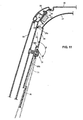
- FIG. 27 is a view of the second embodiment, corresponding to FIG. 15.
- Hereinafter, preferred embodiments (modifications, examples) of the present invention will be described. It should be also understood that even though the embodiments (modifications, examples) are separately described, single features thereof may be combined to additional embodiments (modifications, examples).
- A
vehicle 1 comprises afront seat 2, asecond row seat 3 that is provided behind thefront seat 2, and a third row seat 4 that is provided behind thesecond row seat 3, as shown in FIG. 1. Thevehicle 1 comprises aside door 5 for thefront seat 2 and aside door 6 for thesecond row seat 3, and it also comprises an A pillar 7 (front pillar or post), one or more intermediate pillars or posts (specifically aB pillar 8, a C pillar 9) and a D pillar 10 (rear pillar or post), which are disposed from the front in order. Herein, theC pillar 9 preferably corresponds to a "center pillar" or "intermediate pillar" and the D pillar preferably corresponds to a "rear pillar". - The
side door 5, which opens and closes an ingress/egress opening 11 between theA pillar 7 and theB pillar 8, includes aside window glass 12 that can be driven substantially vertically. Theside door 6, which opens and closes an ingress/egress opening 13 between theB pillar 8 and theC pillar 9, includes aside window glass 14 that can be driven substantially vertically. Arear side opening 15 is formed between theC pillar 9 and theD pillar 10, which is at least partly covered by aside window glass 16. Herein, theside window glasses pillars - The three
side window glasses curtain airbag 17 from the inside when a vehicle side crash or a vehicle turnover occur or these are predicted, for example. Thecurtain airbag 17 preferably is folded or collapsed (in a regular and/or irregular manner) in a single bar shape in its folded state, which is fixed or fixable to a vehicle body substantially along or near edge portions of thewindow glasses curtain airbag 17 is fixed to (preferably a lower portion of) theA pillar 7, its rear end portion is fixed to (preferably a lower portion of) theD pillar 10, and its intermediate portion (preferably its substantially center portion) is fixed to a vehicle body preferably on a line that longitudinally interconnects respective upper edge portions of theside window glasses - The
curtain airbag 17 inflates along theside window glasses curtain airbag 17 preferably is configured so that its lower end can be located slightly below respective lower edge portions of theside window glasses - The
curtain airbag 17 is formed in at least one bag shape preferably by sewing or bonding or connecting two sheets of base clothes having substantially the same shape along their peripheries (not shown). Inflation gas can be supplied to thecurtain airbag 17 through at least onegas inlet 17m. At the two sheets of base clothes are provided one or more seams orconnected portions 17a - 17e that are formed in a curve shape or in a closed-loop shape as shown in FIG. 2. Portions enclosed by theseams non-inflatable portions 17f, 17g, respectively, into which the gas is not supplied or substantially cannot diffuse. The other portion forms an inflatable portion. Herein, thenon-inflatable portions 17f, 17g are formed so that these portions are located at positions that are away or offset from a head portion of a passenger seated in the seats 2 - 4. The provision of these non-inflatable portions may help thecurtain airbag 17 inflate promptly. Theseams curtain airbag 17 from becoming too wide. A plurality of fixing portions P...P are provided at the upper edge portion of thecurtain airbag 17 along the upper edges of theside window glasses tether 17h is provided at the front end portion of thecurtain airbag 17, and it is connected to (preferably the lower portion of) theA pillar 7. - In the
curtain airbag 17 that is stored as described above, its inflation or deployment direction will be the direction of the airbag inflating from its stored position that is fixed to the vehicle body. For example, in a case where thecurtain airbag 17 is stored in such a manner that its lower end portion is folded or collapsed substantially in a bellow shape, the direction of a lower tip end of its lower end inflating may be the inflation direction. - As shown in FIGS. 1 and 2, an
inflator 18 is provided at or close to an upper portion of the vehicle body preferably adjacent to or in front of theC pillar 9, which supplies the inflation gas to thecurtain airbag 17. Gas pressure generated by theinflator 18 is supplied to thecurtain airbag 17 in the stored state via asupply duct 19. A downstream end of thesupply duct 9 is connected to thegas inlet 17m of thecurtain airbag 17 preferably at a location in front of thecenter pillar 9. - The pillars 7 - 10 are at least partly covered by one or more respective pillar trims from the inside of the vehicle. As shown in FIGS. 3 and 4, for example, the
C pillar 9 is covered by a C pillar trim 56, and aD pillar 10 is covered by a D pillar trim 26. Also, a roof panel 30 (see FIG. 5) is at least partly covered by aroof trim 37 at its inside. The roof trim 37 is made of a soft and flexible material, such as a urethane foam covered by clothes, which may be easily deformed by a small force applied like a pressing force by a finger. The respective pillar trims preferably are made of synthetic resin, such as polypropylene, which are harder than theroof trim 37. Particularly, the D pillar trim 26 preferably is at least partly made of TPO (thermoplastic olefin) that may not be broken easily even at a considerably low temperature (minus 20 degrees centigrade or lower), thereby which may not be easily deformed by the relatively small force like the pressing force by the finger. Thus, the D pillar trim 26 particularly is so harder than the roof trim 37 that it may not be hurt or damaged improperly by any loaded baggage or the like. Herein, preferably only a particular part of the D pillar trim 26, not a whole part of it, may be made of the above-described synthetic resin. - At an outside end portion of the
roof panel 30, as shown in FIG. 6, is provided aroof side rail 30R, as a reinforcement member, which comprises a roof sideinner panel 31 and a roof sideouter panel 32 and preferably has its substantially closed cross section extending substantially longitudinally. A connectingflange 33 is formed at or near a lower end portion of theroof side rail 30R so as to extend substantially downward. To this connectingflange 33 is to be fixed the upper edge portion of theside window glass 16 preferably via an adhesive 34 or by bonding. As shown in FIGS. 4 and 6, an outside edge portion of the roof trim 37 between the C pillar trim 56 and the D pillar trim 26 projects substantially outward a little and is located right near theside window glass 16. The outside end portion of the roof trim 37 is to be held at the connectingflange 33 with anedge molding 35. - The
D pillar 10 preferably is formed to have a substantially closed cross section with aninner panel 21 and anouter panel 22, and has a connectingflange 23 to extend substantially forward a little at its front end portion as shown in FIG. 7. A rear edge portion of theside window glass 16 is fixed to an outer face of the connectingflange 23 preferably via an adhesive 24 or bonding as shown in FIG. 8. The D pillar trim 26 covering theD pillar 10 preferably is formed to have a bent or angled or curved or substantially L-shaped cross section substantially in a horizontal direction as shown in FIG. 7, which comprises aside face portion 26b that substantially extends widely in the vehicle longitudinal direction and afront face portion 26c that extends substantially outward from a front end of theside face portion 26b and widely in the vehicle width direction. Anoutside edge portion 26a (hereinafter, referred to as a specifiededge portion 26a) of thefront face portion 26c is located right near the rear edge portion of theside widow glass 16 and extends near the connectingflange 23. Thefront face portion 26c is, as shown in FIG. 5, provided slightly slant in the plan view (when viewed from the top of the vehicle body) in such a manner that the specifiededge portion 26a is located gradually rearward. - As shown in FIGS. 9 - 11, the
C pillar 9 preferably is formed to have a substantially closed cross section with aninner panel 51 and anouter panel 52, and an upper end of the C pillar trim 56 at least partly covering theC pillar 9 from the inside is slightly away from the inner face (inner panel 51) of theC pillar 9 to generate a gap between theC pillar 9 and the C pillar trim 56 in the vehicle width direction. - The
curtain airbag 17 in the stored or collapsed state is to be fixed to the vehicle body via one or more attachingbrackets bracket 41 shown in FIG. 7 is the one for theD pillar 10, and the attachingbracket 42 shown in FIG. 11 is the one for theroof side frame 30R. The attachingbracket 42 has anextension portion 42a that extends substantially downward. Thisextension portion 42a is provided slant or oblique in such a manner that its lower-side portion is located substantially inward and it is substantially directed slightly inward from the inside end portion of the C pillar trim 56. Thisextension portion 42a can guide thecurtain airbag 17 inflating properly and surely, without any interference with the C pillar trim 56. - An exemplified provision of the
curtain airbag 17 in the stored or collapsed state substantially along the portion from the upper edge portion to the rear edge portion of theside window glass 16 will be described referring to FIG. 5. Herein, an illustration of the above-described attachingbrackets curtain airbag 17 clearer in this figure. As apparent from FIG. 5, thecurtain airbag 17 in the stored state or collapsed is provided in such a manner that it extends substantially longitudinally from the front end portion to the rear end portion of the upper edge portion of theside window glass 16 in the plan view, and that its portion extending substantially along the rear edge portion of theside window glass 16 is located at the most outside position. The inflator 18 preferably substantially extending longitudinally is foxed to theroof side rail 30R via an attaching bracket, not illustrated. - Beside or corresponding to the
seats respective seatbelts seatbelts retractors D pillars - Hereinafter, the structure of the
seatbelt anchor 72 attached to theC pillar 9 will be described specifically. As shown in FIG. 12, theseatbelt anchor 72 is to be fixed to theinner panel 51 at its one end, and the other end of theseatbelt anchor 72 comprises aboss member 74 that extends through ahole portion 56a formed preferably at the C pillar trim 56, aseatbelt engaging member 75 that has ahole 75a for theseatbelt 71, abolt 76 that rotatably or releasably attaches the engagingmember 75 to theboss member 74, and acase 77 that at least partly covers the engagingmember 75 and/or a head of thebolt 76. One or more, preferably a plurality ofribs 77a are formed at an inner face of thecase 77. Theribs 77a can absorb the impact when theseatbelt anchor 72 is hit by a passenger body, an object or the like. Accordingly, there is a limit to a minimization of the width (thickness) of theseatbelt anchor 72. Further, there exists a small gap S between the upper face portion of the C pillar trim 56 and alower face portion 77c of thecase 77 that substantially faces the C pillar trim 56. This gap S is to particularly provide a smooth rotation of theseatbelt anchor 72 and/or to absorb any manufacturing error and prevent any improper contact noises of the members. That is, theseatbelt anchor 72 is provided to project inward from the inner face of the C pillar trim 56 so as to meet the above-described needs. - Herein, there is provided a slant or
oblique face 77d at an upper portion of ansurface portion 77b of theseatbelt anchor 72. Theslant face 77d is formed in such a manner that its lower portion is located inward (or more inward as compared to its upper part). Theslant face 77d is slant relative to a horizontal face that is substantially perpendicular to the face of the C pillar trim 56. At a side portion of thesurface portion 77b is provided aslant face 77e that is steeper than the above-describedslant face 77d. Namely, the incline of the upper portion of theseatbelt anchor 72 is gentler than that of a front portion of theseatbelt anchor 72. Further, since the incline of theslant face 77d is not so steep, theseatbelt anchor 72 is configured so that the length from its rotational center to its upper end is longer than that from its rotational center to its front or rear end. According to the above-described structure of the slant faces, in a case where e.g. the head of the passenger hits theseatbelt anchor 72 from above, it may tend to hit against theslant face 77d. Thereby, the impact absorption may be improved. - Herein, the slant of the
slant face 77d is configured, as shown in FIG. 11, so that an angle θ that is formed between a line interconnecting an intersection point of an extension line extending from the inner face of the C pillar trim 56 and theslant face 77d and an front edgeupper end 26u of the D pillar trim 26 and a line of the incline of theslant face 77d preferably is within a range of approximately 120 to 200 degrees. In the case shown in FIG. 11, the angle θ preferably is set in a range of about 130 to about 170 degrees, more preferably of about 140 to about 160 degrees, most preferably to about 150 degrees. It should be understood that theslant face 77d needs not to be perfectly flat, but may be somewhat convex. In such case, the above angle θ is to be determined based on a tangent to the surface of theslant face 77d at the point of intersection. - Herein, the
slant face 77d is provided in such a manner that a clear rearview from a driver's seat is not substantially deteriorated by theseatbelt anchor 72 that rotates by a specified (predetermined or predeterminable) rotational or pivotal angle (for example, an angle of about counterclockwise 60 degrees from the state shown in FIG. 9 to the state shown in FIG. 13) due to application of theseatbelt 71. Specifically, theslant face 77d is formed on thesurface portion 77b in such a manner that when theseatbelt anchor 72 rotates by the specified (predetermined or predeterminable) rotational or pivotal angle, theslant face 77d formed is positioned even at the upper end of theseatbelt anchor 72. Thereby, theseatbelt anchor 72 may not deteriorate the clear rearview from the driver's seat properly, compared to a case where theslant face 77d is not formed on thesurface portion 77b and therefore the upper portion of thesurface portion 77b projects toward the inside of the vehicle to a certain degree. The above-described specified rotational or pivotal angle may be set properly by considering relationships ofseatbelt anchor 72 and thesecond row seat 3 in their longitudinal positions. - The C pillar trim 56 comprises a
lower face portion 56b that preferably is substantially in parallel to the side face of the vehicle body, a frontslant face portion 56c that substantially extends forward and outward from thelower face portion 56b, and a rearslant face portion 56d that substantially extends rearward and outward. Thus, the C pillar trim 56 is formed in a curved shape in such a manner that its intermediate or central portion projects toward the inside of the vehicle as shown in FIG. 10. - Both the
lower face portion 56b of the C pillar trim 56 and thelower face portion 77c of theseatbelt anchor case 77 have a substantially flat face facing each other substantially in parallel with the above-described gap S between them. Herein, the width of thelower face portion 56b of the C pillar trim 56 in the longitudinal direction is set such that the outer periphery of thesurface portion 77b of theseatbelt anchor case 77 may not extend beyond the frontslant face portion 56c and the rearslant face portion 56d when theanchor 77 rotates or pivots as shown in FIG. 13. Thereby, even when theseatbelt anchor 72 rotates or pivots counterclockwise by the specified at an angle different from 0° or 180°, preferably substantially angle (preferably in a range of about 40 to 70 degrees, more preferably of about 60 degrees) due to the application of theseatbelt 71 to the passenger as shown in FIG. 13, the gap S in the vehicle width direction between thelower face portion 56b of the C pillar trim 56 and thelower face portion 77c of theseatbelt anchor 72 may become large. Herein, the outer periphery of theseatbelt anchor 77 may be configured not to extend beyond the frontslant face portion 56c or the rearslant face portion 56d. - As shown in FIG. 3, a
seatbelt holding member 94 is provided at a portion of aquarter trim 91 at least partly forming the inner face of the vehicle rear portion that is located below theC pillar 9. Theseatbelt holding member 94, which preferably is a U-shaped clip member with an front-open end in the plan view, functions as a member to hold theseatbelt 71 when theseatbelt 71 is not applied to the passenger. Herein, theseatbelt holding member 94 is provided in such a manner that when theseatbelt 71 is at least partly inserted into its front-open end portion to be held by the holdingmember 94, theseatbelt anchor 72 can be held such that its vertical direction has a specified (predetermined or predeterminable) angle (preferably of about ± 30 degrees) or less relative to the inflation direction of thecurtain airbag 17 that is located at the C pillar trim 56 (a direction substantially perpendicular to a lower-end line 17L of the curtain airbag 17), as shown in FIG. 9. - The
lower face portion 56b of the C pillar trim 56 of theC pillar 9 has anuneven portion 56e that is formed near the upper edge portion of theseatbelt anchor 72 so as to overhang or to be undercut in such a manner that the upper overhanging portion is located inward from an outside end portion of the upper edge portion of theseatbelt anchor 72. In other words, the amount of projection of the overhanging or undercut portion toward the inside is set to be greater than the above-describe gap S. Theuneven portion 56e preferably extends substantially horizontally in the longitudinal direction, and itsrear end 56g is positioned at the substantially same height level as aportion 56h that is located above theseatbelt anchor 72. - The
seatbelt anchor 62 provided at theB pillar 8 is located, as shown in FIG. 14, lower a straight line TL1 that interconnects an upper end of the D pillar trim 26 and a front-end fixing portion Pf of thecurtain airbag 17 and above a straight line L1 that interconnects the rear end of theuneven portion 56e and the front-end fixing portion Pf of thecurtain airbag 17. - Next, the operation of the structure described above will be described. When the vehicle side crash or the vehicle turnover are detected or predicted while the
curtain airbag 17 is in the stored state, theinflator 18 is activated. The gas pressure generated by theinflator 18 is supplied to thecurtain airbag 17, and then thecurtain airbag 17 inflates in the vehicle as shown in FIG. 2. - The inflation of the
curtain airbag 17 progresses in the substantially downward direction shown by an arrow α in FIG. 6 (theinflated curtain airbag 17 is shown by a one-dotted broken line). The roof trim 37 is so soft that it can be easily deformed downward. Also, the inflation of thecurtain airbag 17 is carried out by moving (deforming) at least an upper portion of theoutside edge portion 26a of the D pillar trim 26 substantially in the forward direction shown by an arrow β in FIG. 7 (theinflated curtain airbag 17 is shown by a one-dotted broken line). In FIG. 7 thecurtain airbag 17 inflates through a gap generated between theside window glass 16 and theoutside edge portion 26a. Herein, thecurtain airbag 17 includes an inflatable portion to inflate in the vehicle width direction at theoutside edge portion 26a. Therefore, the upper portion of theoutside edge portion 26a needs to be substantially moved forward and toward the inside of the vehicle sufficiently. A portion of thecurtain airbag 17 substantially along the rear edge portion of theside window glass 16 is directed outward greatly as shown by an arrow γ in FIG. 7. Accordingly, the gap between theoutside edge portion 26a and theside window glass 16 that is a passage of thecurtain airbag 17 inflating can be properly small. - Herein, the
gas inlet 17m for thecurtain airbag 17 preferably is located in front of thecenter pillar 9, so the inflation gas will be supplied mainly toward a front part of the airbag. The D pillar trim 9 is made of relatively hard material or a material having a relatively low resiliency and/or relatively high stiffness and such as relatively hard synthetic resin, so the rear end portion of thecurtain airbag 17 may not inflate easily. Accordingly, the rear end portion of theairbag 17 may remain inside the rear pillar trim 9 even if the front portion of the airbag has already inflated outside. Namely, in a case where the inflation gas is arranged to be mainly supplied toward the front portion (corresponding to thefront seat 2, for example) of thecurtain airbag 17 at the initial stage of the airbag inflation with the provision of the one or morenon-inflatable portions 17f, 17g and/or one or more seams or connectingportions curtain airbag 17, the airbag shows its inflation state shown in FIG. 14, for example. In this case, the upper portion of the rear end portion of thecurtain airbag 17 catches on the front edge portion of the upper end portion of the D pillar trim 26, so the tension line TL1 may be generated on the line that interconnects the front-end fixing point Pf and an front edge portion X of the upper end portion of the D pillar trim 26. - This state will be described further. As shown in FIG. 16, since the specified
edge portion 26a of the D pillar trim 26 is located outward from the inner face of the C pillar trim 56 of theC pillar 9, thecurtain airbag 17 inflates so as to lower contacting the C pillar trim 56 by the pressing of the above-described tension. Herein, at an early stage that thecurtain airbag 17 inflates as shown in FIG. 14, the outside face of thecurtain airbag 17 may contact the C pillar trim 56, but its pressing force is relatively small as compared to a later stage that thecurtain airbag 17 inflates toward the lower portion of the D pillar trim 26. That is, when thecurtain airbag 17 inflates pressing against outward the forward portion of the roof trim 37 that is located in front of the upper end portion of the D pillar trim 26, it inflates with a first pressing force against the upper part of the C pillar trim 56 that is positioned above the tension line TL1. Meanwhile, when thecurtain airbag 17 inflates substantially downward from the upper end portion of the D pillar trim 26, it inflates with a second pressing force, which is greater than the first pressing force, against the lower part of the C pillar trim 56 that is positioned below the tension line TL1. Accordingly, if theseatbelt anchor 72 is located above or below the tension line L1, thecurtain airbag 17 may easily catch on thisanchor 72 during its further inflation. Further, the lower edge portion of thecurtain airbag 17 may easily get into the gap S between thecase 77 of theseatbelt anchor 72 and the C pillar trim 56. - According to the present embodiment, the
slant face 77d is provided at thecase 77 of theseatbelt anchor 72 in such a manner that its lower portion is located inward, as described above. Thereby, even if the lower end of the inflatingcurtain airbag 17 contacts the inner face of theseatbelt anchor 72, theairbag 17 can be properly prevented from catching on theseatbelt anchor 72. Accordingly, any deterioration of the inflation of the airbag can be prevented. - Further, according to the present embodiment, the inner face of the
C pillar 9 has theuneven portion 77e that is formed near the upper edge portion of theseatbelt anchor 72 so as to overhang or to be undercut in such a manner that the upper overhanging or undercut portion is located inward from the outside end portion of the upper edge portion of theseatbelt anchor 72, as described above. Thereby, the gap S between theseatbelt anchor 72 and theupper face 56b of the C pillar trim 56 of theC pillar 9 is at least partly hidden behind the upper-overhanging portion of theuneven portion 77e, when viewed from above. Accordingly, it becomes difficult for thecurtain airbag 17 to get into the gap S, so theairbag 17 can be further properly prevented from catching on theseatbelt anchor 72. Making the gap S small or providing theslant face 77d are particularly effective in the case where theseatbelt anchor 72 is located above or below the tension line TL1. - Then, when the inflation proceeds towards or to the complete state (specified inflation state) as shown in FIG. 15, the
curtain airbag 17 provides a tension line TL3 on a line that interconnects the front fixing point Pf and a rear fixing point Pr, thereby generating a sufficient resistance force against the vehicle turnover or the like. - Further, according to the present embodiment, the
seatbelt anchor 72 preferably is provided so as to rotate or pivot around theaxis 74 that extends substantially in the vehicle width direction, and the above-describedslant face 77d is provided in such a manner that the clear rearview from the driver's seat is not substantially deteriorated by theseatbelt anchor 72 rotating or pivoting by the specified (predetermined or predeterminable) rotational or pivotal angle. Thereby, in addition to the above-described effects, an effect of improvement of the clear rearview from the driver's seat can be obtained. - Also, the gap S in the vehicle width direction between the
upper face portion 56b of the C pillar trim 56 and thelower face 77c of theseatbelt anchor 72 that faces theupper face 56b of the trim 56 when theseatbelt anchor 72 rotates due to the application of theseatbelt 71 to the passenger as shown in FIG. 13 is configured not to become larger than the gap at the time of an non-application of theseatbelt 71. Thereby, in theseatbelt anchor 72 in that the length from its rotational or pivotal axis to its upper end is configured to be longer than the length from its rotational axis to its front end or rear end in order to provide theslant face 77d like the present embodiment, the lower end of thecurtain airbag 17 from getting into the gap S despite the rotation or pivotal movement of theseatbelt anchor 72. Thus, theairbag 17 can be prevented from catching. - Namely, if the longitudinal length of the
lower face portion 56b of the C pillar trim 56 is short, in a case where the C pillar trim 56 is inclined forward, the rear end of theseatbelt anchor 72 may move rearward beyond thelower face portion 56b to the position corresponding to the rearslant face portion 56d, so that the gap S may become improperly large. According to the present embodiment, however, such a situation may substantially not occur. - Further, there is provided the
seatbelt holding member 94 in such a manner that when theseatbelt 71 is not applied, theseatbelt anchor 72 is held such that its vertical direction is directed in the inflation direction of thecurtain airbag 17. Thereby, the lower end of thecurtain airbag 17 contacts and slides down on the inner face of theseatbelt anchor 72, so that theairbag 17 can be properly prevented from catching on theseatbelt anchor 72. - Herein, according to the
curtain airbag 17 of the present embodiment, as described above, the front side portion of theairbag 17 inflates first until its rear end portion inflates outward from the D pillar trim 26. Thus, thelower end line 17L of thecurtain airbag 17 becomes a line that extends from the front edgeupper end 26u of the D pillar trim 26, as shown in FIG. 3, and rotates or pivots counterclockwise around this front edgeupper end 26u in accordance of the rotation or pivotal movement of theairbag 17. - In the present embodiment, the
rear end 56g of theuneven portion 56e is positioned at the same height level as theportion 56h that is located above theseatbelt anchor 72. Thereby, as apparent from thelower end line 17L shown in FIG. 9, when thelower line 17L of thecurtain airbag 17 lowers to therear end 56g of theuneven portion 56e, this lower end goes down below the upper end of theseatbelt anchor 72 and is located substantially inward from theseatbelt anchor 72. Accordingly, thecurtain airbag 17 can be surely prevented from catching on theseatbelt anchor 72. - Moreover, while the
seatbelt anchor 62 is provided at the inner face of theB pillar 8, theuneven portion 56e is provided at theC pillar 9 of the present embodiment, so thecurtain airbag 17 is likewise moved inward even at the portion of theB pillar 8 and thereby thecurtain airbag 17 may be prevented from catching on theseatbelt anchor 62 at this position as well. - Herein, even in the case where the
curtain airbag 17 provides the tension line TL1 on the straight line that interconnects the upper end of the rear pillar trim 26 and the front fixing point Pf of thecurtain airbag 17 at the inflation initial stage as described above, thecurtain airbag 17 can be surely moved inward at the existing position of theseatbelt anchor 62 by providing theseatbelt anchor 62 at a portion of theB pillar 8 that is located below the tension line TL1 and above the straight line L1 interconnecting the rear end of theuneven portion 56e and the front fixing portion Pf of the curtain airbag. Thereby, the lower end of thecurtain airbag 17 can be further surely prevented from catching on theseatbelt anchor 62. The present invention is applicable to a known type ofseatbelt anchor 62 that can slide vertically. - Herein, the
uneven portion 56e may be configured in different manners as described below. - While the above-described
uneven portion 56e of theC pillar 9 is provided over the longitudinal length of thelower face portion 56b of theC pillar 9, its modification shown in FIGS. 17 and 18 is configured so that its uneven 56e' of its C pillar 56' is provided only at the rear side portion of thelower face portion 56b'. According to the modification, likewise, thecurtain airbag 17 is moved inward (toward the inside of the vehicle) and the same operation can be attained. Herein, the uneven portion may be provided at a further rearward portion or at a forward portion, and thus a design flexibility of the C pillar trim may be increased. - According to another modification, as shown in FIG. 19, its
uneven portion 56e" of its C pillar trim 56" of theC pillar 9 has adownward extension portion 56f" at its rear portion. A lower end (rear end) 56g" of thedownward extension portion 56f" is located below aportion 56h" that is positioned above theseatbelt anchor 72. Thereby, the inflatingcurtain airbag 17 is configured in such a manner that it can be lifted to the height of the center of theseatbelt anchor 72 by theuneven portion 56e", so thecurtain airbag 17 can be further surely prevented from catching on theseatbelt anchor 72. - Herein, there is further provided means for facilitating movement of the D pillar trim 26 to allow the
curtain airbag 17 to inflate outside. Herein, three specific examples of this means will be described referring to FIGS. 20 - 22. - In a first example shown in FIG. 20, the D pillar trim 26 is configured to be moved forward substantially entirely away from the
D pillar 10 when it receives a forward pushing force that is greater than a specified (predetermined or predeterminable) value. Namely, there is provided asupport stay 29 so as to project rearward from a back face of thefront face portion 26c of the trim 26, and/or an engaging projectingportion 29a is formed at its tip end. The engaging projectingportion 29a is configured to engage with theD pillar 10. Herein, when the forward pushing force with the specified (predetermined or predeterminable) value or greater acts on thefront face portion 26c, the engagement of the projectingportion 29a with theD pillar 10 is released, so that the D pillar trim 26 is easily moved forward substantially entirely as shown by a one-dotted broken line in FIG. 20. Thereby, the inflation of thecurtain airbag 17 can be improved. - In a second example shown in FIG. 21, an upper specified (predetermined or predeterminable) portion of the
front face portion 26c of the D pillar trim 26 is comprised of aseparate cover member 27. Thecover member 27 is to be attached to the D pillar trim 26 (trim body) via ahinge 28 in such a manner that their front faces are substantially flat. Thehinge 28 is made of a soft material, such as synthetic resin, for example, preferably in a loop shape, so as to make thecover member 27 rotate or pivot smoothly around itself. At thecover member 27 is provided asupport stay 27 so as to project rearward from a back face of themember 27, and an engaging projectingportion 27b is formed at its tip end. The engaging projectingportion 27b is configured to engage with theD pillar 10. Accordingly, when thecurtain airbag 17 inflates, the engagement of the projectingportion 27b with theD pillar 10 is released, so that thecover member 27 is easily rotated or pivoted forward around thehinge 28 as shown by a one-dotted broken line in FIG. 21. Thereby, the inflation of thecurtain airbag 17 can be properly improved. Accordingly, the similar or ssame effects as that of the first example can be obtained. - In a third example shown in FIG. 22, a cover portion 27', which corresponds to the above-described
cover member 27, is formed integrally or unitarily at thefront face portion 26c of the D pillar trim 26. At least onegroove 26d that functions as a hinge mechanism is formed at a back face of thefront face portion 26c at a border between the cover portion 27' and the other portion. Its closed state at the time thecurtain airbag 17 is folded in the stored state is shown by a solid line and its open state at the time of the inflation of thecurtain airbag 17 is shown by a one-dotted broken line in FIG. 22. According to the third example, the similar or same effects as that of the first example can be obtained as well. - While the above-described embodiment shows the
seatbelt anchor 72 of theseatbelt 71 for theseat 3 that is provided at theC pillar 9, the present invention is applicable to theseatbelt anchor 72 that is provided not at theC pillar 9 itself, but near theC pillar 9 or at aB pillar 8. For example, there is provided a bracket at theroof side rail 30R near theC pillar 9 so as to extend to a position near theside window glass 16, and theseatbelt anchor 72 may be attached to this bracket. - Further, the above-described embodiment is applicable to a case where a tension line TL2 is provided as shown in FIG. 23. That is, in the case where the inflation gas is supplied toward the center of the
curtain airbag 17 in the longitudinal direction, the gas is forcibly supplied to a lower portion of the lower edge of theairbag 17 that is located below thegas inlet 17m, so that the front portion of theairbag 17 inflates greatly as shown in FIG. 23 despite of the rear portion of the airbag with substantially no inflation. In this state, likewise, thecurtain airbag 17 provides the tension line TL2 that interconnects a portion Y of the lower edge of theairbag 17 that is located below thegas inlet 17m and the front edge portion X of the upper end portion of the rear pillar trim. In this case, while thecurtain airbag 17 may contact the C pillar trim 56 at its outside face before the curtain inflates as shown in FIG. 23, its pressing force against the C pillar trim 56 is relatively small compared to the moment thecurtain airbag 17 subsequently inflates toward the lower portion of the D pillar trim 26. Therefore, if theseatbelt anchor 72 is provided at a portion of the C pillar trim 56 that is located on or below the tension line TL2, the same problem as the case of tension line TL1 may occur for the further inflation. In this case, however, the above-described effects can be attained as well. - The present embodiment will be described referring to FIGS. 24 - 27. According to the present embodiment, the seatbelt anchors 62', 72' are provided at a higher level position than those in the previous embodiment, respectively. Particularly the seatbelt anchor 72' provided at the
C pillar 9 is provided above the tension line TL1 and the tension line TL2. According to the present embodiment, since the tension and the pressing force at the moment the curtain airbag goes over the seatbelt anchor 72' is not so large, thecurtain airbag 17 may not catch on the seatbelt anchor 72' and the lower end of thecurtain airbag 17 may not get into the above-described gap S. Thereby, the proper inflation of thecurtain airbag 17 can be provided. Herein, the portion above the tension line TL1 or the tension line TL2 corresponds to the specified upper portion of the inner face of the center pillar in the claim. - When the inflation is complete as shown in FIG. 27, the
curtain airbag 17 provides the tension line TL3 on the line interconnecting the front fixing point Pf and the rear fixing point Pr, thereby generating a sufficient resistance force against the vehicle turnover or the like. - Herein, the above-described tension lines TL1, TL2, TL3 are just examples for the above-described structure with the curtain airbag, roof trim, D pillar trim, and so on. Accordingly, their incline or height may differ depending on modifications of the structure. However, the present invention is applicable to these modifications. In a case where a plurality of tension lines are provided, the seatbelt anchor can be provided above the tension line that extends across the center pillar at the highest level. In the case where the tension line TL2 and the tension line TL1 are provided, the seatbelt anchor 72' may be provided above the tension line TL2, and the provision of the seatbelt anchor 72' above the tension line TL1 can surely improve the inflation.
- The present invention should not be limited to the above-described embodiments (modifications, examples), but any other modifications and improvements may be applied within the scope of a sprit of the present invention.
- Particularly, it should be understood that the present invention is applicable also to vehicles having only three pillars or posts (front, intermediate and rear pillar).
Claims (15)
- An interior structure of a vehicle (1) equipped with a curtain airbag, comprising:a roof trim (37) at least partly forming a ceiling;a rear pillar trim (26) forming an inner face of a rear pillar (10) that is located at a rear portion of the vehicle (1), the rear pillar trim (26) being made of a material, preferably of synthetic resin, that is harder than a material making the roof trim (37);a seatbelt anchor (72; 72') provided at an inner face of an intermediate pillar (9; 8) of the vehicle (1) that is located in front of the rear pillar (10), the seatbelt anchor (72; 72') projecting inside of the vehicle (1); anda curtain airbag (17) provided inside a side edge portion of the roof trim (37) and the rear pillar trim (26) along at least from an upper front portion of the intermediate pillar (9; 8) to the rear pillar (10), the curtain airbag (17) being configured to inflate at least partly covering at least an inner face of a side window portion of the vehicle (1) that is located in front of a front edge portion of the rear pillar (10) including the intermediate pillar (9; 8), when inflation gas is supplied thereto under a specified condition,wherein said curtain airbag (17) is configured to inflate substantially contacting the inner face of the intermediate pillar (9; 8), and there is provided a restraint structure operative to restrain the curtain airbag (17) inflating from catching on said seatbelt anchor (72; 72').
- The interior structure of a vehicle (1) equipped with a curtain airbag of claim 1, wherein there is provided at least one slant face (77d) at an upper portion of the seatbelt anchor (72), the slant face (77d) being formed in such a manner that a lower portion thereof is located inward, which forms part of said restraint structure.
- The interior structure of a vehicle (1) equipped with a curtain airbag of claim 2, wherein said seatbelt anchor (72) is provided at the inner face of the intermediate pillar (9; 8) so as to rotate or pivot around an axis that extends substantially in a vehicle width direction, and said slant face (77d) is provided at the upper portion of the seatbelt anchor (72) in such a manner that a clear rearview from a driver's seat (2) is not substantially deteriorated by the seatbelt anchor (72) rotating or pivoting by a specified rotational or pivotal angle for application of a seatbelt (71) to a passenger.
- The interior structure of a vehicle (1) equipped with a curtain airbag of claim 2 or 3, wherein said intermediate pillar (9; 8) comprises a intermediate pillar body and a intermediate pillar trim (56) that at least partly covers the intermediate pillar body and form an inner face of the intermediate pillar (9; 8), the intermediate pillar (9; 8) is formed in such a manner that an intermediate portion thereof projects toward inside of the vehicle (1), and a gap (S) in a vehicle width direction between an inner face (56b) of the intermediate pillar trim (56) and a face (77c) of the seatbelt anchor (72) that faces said inner face (56b) of the intermediate pillar trim (56) preferably when the seatbelt anchor (72) rotates or pivots due to the application of the seatbelt (71) is configured not to become larger than the gap at the time of an non-application of the seatbelt (71).
- The interior structure of a vehicle (1) equipped with a curtain airbag of any one of the preceding claims 2 to 4, wherein said curtain airbag (17) is configured in such a manner that the inflation gas is supplied thereto from a specified location in front of the intermediate pillar (9; 8), said seatbelt anchor (72) is configured such that an incline of the upper portion thereof is gentler than that of a front portion thereof, the seatbelt anchor (72) is provided so as to rotate or pivot around an axis that extends substantially in a vehicle width direction, and there is provided a seatbelt holding member (94) to hold the seatbelt anchor (72) at a specified rotational or pivotal position such that a vertical direction of the seatbelt anchor (72) has a specified angle or less relative to an inflation direction of the curtain airbag (17) when the seatbelt (71) is not applied.
- The interior structure of a vehicle (1) equipped with a curtain airbag of any one of the preceding claims, wherein said inner face (56; 56'; 56") of the intermediate pillar (9; 8) has an uneven portion (56e; 56e'; 56e") that is formed near an upper edge portion of said seatbelt anchor (72) so as to overhang in such a manner that an upper overhanging portion is located inward from an outside end portion of the upper edge portion of the seatbelt anchor (72), which forms part of said restraint structure.
- The interior structure of a vehicle (1) equipped with a curtain airbag of claim 6, wherein said uneven portion (56e; 56e'; 56e") of the intermediate pillar (9; 8) is formed so as to located at least at a rear part of the intermediate pillar (9; 8).
- The interior structure of a vehicle (1) equipped with a curtain airbag of any one of the preceding claims, wherein said curtain airbag (17) is configured in such a manner that the inflation gas is supplied thereto from a specified location in front of the intermediate pillar (9), there is provided an additional intermediate pillar (8) in front of the intermediate pillar (9), and at an inner face of the additional intermediate pillar (8) is provided an interior member (62) to project inward of the vehicle (1).
- The interior structure of a vehicle (1) equipped with a curtain airbag of claim 8, wherein said interior member (62) is provided below a line (TL1) that interconnects an upper end of said rear pillar trim (26) and a front-end fixing portion (Pf) of said curtain airbag (17) and above a line (L1) that interconnects a rear end of said uneven portion (56e) and the front-end fixing portion (Pf) of the curtain airbag (17).
- The interior structure of a vehicle (1) equipped with a curtain airbag of any one of the preceding claims in combination with claim 6, wherein said curtain airbag (17) is configured in such a manner that the inflation gas is supplied thereto from a specified location in front of the intermediate pillar (9; 8), and a rear end (56g; 56g") of said uneven portion (56e; 56e") is positioned at substantially the same height level as or below a front portion (56h; 56h") of the uneven portion (56e; 56e") that is located above the seatbelt anchor (72).
- The interior structure of a vehicle (1) equipped with a curtain airbag of any one of the preceding claims, wherein said seatbelt anchor (72') is located above a tension line (TL1, TL2) that is generated at the curtain airbag (17) so as to extend substantially in a vehicle longitudinal direction when the curtain airbag (17) is in a specified inflation state, which forms part of said restraint structure.
- The interior structure of a vehicle (1) equipped with a curtain airbag of claim 11, wherein said curtain airbag (17) provides a specified tension on a line (TL2) that interconnects a specified portion (Y) of a lower edge portion of the airbag (17) that is located below a gas inlet (17m) and an upper end portion (X) of the rear pillar trim (26) when the curtain airbag (17) is in a specified inflation state, and said seatbelt anchor (72') is located above said line (TL2) of the specified tension.
- The interior structure of a vehicle (1) equipped with a curtain airbag of claim 11 or 12, wherein a front end portion of said curtain airbag (17) is fixed to a vehicle body at a point (Pf) below an upper end portion of the rear pillar trim (26), the curtain airbag (17) provides a specified tension on a line (TL1) that interconnects said fixing point (Pf) and an upper end portion (X) of the rear pillar trim (26) when the curtain airbag (17) is in a specified inflation state, and said seatbelt anchor (72') is located above said line of the specified tension.
- The interior structure of a vehicle (1) equipped with a curtain airbag of any one of the preceding claims, wherein there is provided means (29, 29a, 26c; 27a, 27b, 27, 28; 27', 26d) for facilitating movement of the rear pillar trim (26) to allow the curtain airbag (17) to inflate outside.
- The interior structure of a vehicle (1) equipped with a curtain airbag of any one of the preceding claims, wherein said curtain airbag (17) is configured to inflate with a first pressing force against a specified upper portion of the inner face of the intermediate pillar (9; 8) when the curtain airbag (17) inflates pressing outward the roof trim (37) in front of an upper end portion of the rear pillar trim (26) and inflate with a second pressing force against a portion below said specified upper portion of the inner face of the intermediate pillar (9; 8) when the curtain airbag (17) inflates downward from the upper end portion of the rear pillar trim (26), the second pressing force being greater than the first pressing force, and said seatbelt anchor (72') is located at said specified upper portion of the inner face of the intermediate pillar (9; 8), which forms part of said restraint structure.
Applications Claiming Priority (2)
| Application Number | Priority Date | Filing Date | Title |
|---|---|---|---|
| JP2006261242A JP4923912B2 (en) | 2006-09-26 | 2006-09-26 | Interior structure of vehicle with curtain airbag |
| JP2006260454A JP2008080858A (en) | 2006-09-26 | 2006-09-26 | Interior trim structure of vehicle equipped with curtain airbag |
Publications (3)
| Publication Number | Publication Date |
|---|---|
| EP1905650A2 true EP1905650A2 (en) | 2008-04-02 |
| EP1905650A3 EP1905650A3 (en) | 2008-05-14 |
| EP1905650B1 EP1905650B1 (en) | 2011-05-04 |
Family
ID=38670578
Family Applications (1)
| Application Number | Title | Priority Date | Filing Date |
|---|---|---|---|
| EP07018382A Expired - Fee Related EP1905650B1 (en) | 2006-09-26 | 2007-09-19 | An interior structure of vehicle equipped with curtain airbag |
Country Status (3)
| Country | Link |
|---|---|
| US (1) | US7815217B2 (en) |
| EP (1) | EP1905650B1 (en) |
| DE (1) | DE602007014303D1 (en) |
Cited By (2)
| Publication number | Priority date | Publication date | Assignee | Title |
|---|---|---|---|---|
| FR2972159A1 (en) * | 2011-03-03 | 2012-09-07 | Peugeot Citroen Automobiles Sa | Fastener for fastening seat-belt guide cover trim to roof panel of car, has clipping sleeve allowing fixation of cover trim on head of screw, which receives clipping sleeve, where screw connects guide cover trim to roof panel |
| CN104108370A (en) * | 2013-04-19 | 2014-10-22 | 本田技研工业株式会社 | Configuration structure and in-built structure of three-point type safety belt device |
Families Citing this family (7)
| Publication number | Priority date | Publication date | Assignee | Title |
|---|---|---|---|---|
| DE602007000384D1 (en) * | 2006-03-07 | 2009-02-05 | Mazda Motor | Rear part of a motor vehicle with side airbag device |
| KR20100127982A (en) * | 2009-05-27 | 2010-12-07 | 현대자동차주식회사 | Roof air bag device for controlling open-angle of air bag door |
| DE102011005549A1 (en) * | 2011-03-15 | 2011-07-21 | Takata-Petri Ag, 63743 | Side gas bag for vehicle occupant restraint system of motor vehicle, has inflatable chamber comprising head protection region and overlapping region and tapered from head protection region towards overlapping region |
| KR101294199B1 (en) * | 2012-05-10 | 2013-08-08 | 현대자동차주식회사 | Frontal center curtain airbag for vehicle |
| DE102013224962A1 (en) * | 2013-12-05 | 2015-06-11 | Robert Bosch Gmbh | Arrangement for creating an image of a scene |
| US10343645B2 (en) * | 2017-03-24 | 2019-07-09 | Honda Motor Co., Ltd. | Seatbelt shoulder anchor |
| DE102017216430A1 (en) * | 2017-09-15 | 2019-03-21 | Volkswagen Aktiengesellschaft | Component system for fixing a trim part and motor vehicle |
Family Cites Families (14)
| Publication number | Priority date | Publication date | Assignee | Title |
|---|---|---|---|---|
| JP2718913B2 (en) * | 1995-11-21 | 1998-02-25 | 三桜工業株式会社 | Shoulder anchor adjuster for seat belt |
| JP3076855B2 (en) * | 1996-11-07 | 2000-08-14 | 豊田合成株式会社 | Side airbag device airbag |
| DE19718203A1 (en) * | 1997-04-30 | 1998-11-05 | Daimler Benz Ag | Airbag curtain, in particular for a vehicle window |
| JP3110709B2 (en) * | 1997-09-04 | 2000-11-20 | トヨタ自動車株式会社 | Head protection airbag device |
| JP3497726B2 (en) * | 1998-03-26 | 2004-02-16 | 本田技研工業株式会社 | Seat belt tongue mechanism |
| US6371512B1 (en) * | 1998-08-03 | 2002-04-16 | Toyota Jidosha Kabushiki Kaisha | Airbag apparatus for head-protecting |
| JP3460636B2 (en) * | 1999-08-23 | 2003-10-27 | トヨタ自動車株式会社 | Head protection airbag device |
| GB2367040B (en) | 2000-09-25 | 2003-11-12 | Ford Global Tech Inc | A grab handle and seatbelt support ring and a method relating thereto |
| GB2369805B (en) * | 2000-12-08 | 2004-02-18 | Autoliv Dev | Improvements in or relating to an air-bag arrangement |
| JP3759496B2 (en) * | 2002-12-20 | 2006-03-22 | 本田技研工業株式会社 | Crew restraint system |
| JP2004196250A (en) * | 2002-12-20 | 2004-07-15 | Honda Motor Co Ltd | Occupant restraining device |
| US7198300B2 (en) * | 2004-04-30 | 2007-04-03 | Honda Motor Co., Ltd. | Actuator for an adjustable seat belt D-ring anchor |
| US7445233B2 (en) * | 2004-09-22 | 2008-11-04 | International Automotive Components Group North America, Inc. | Guiding pillar trim for a side-curtain airbag system |
| JP4419970B2 (en) | 2006-02-23 | 2010-02-24 | マツダ株式会社 | Vehicle occupant protection device |
-
2007
- 2007-08-28 US US11/892,828 patent/US7815217B2/en active Active
- 2007-09-19 DE DE602007014303T patent/DE602007014303D1/en active Active
- 2007-09-19 EP EP07018382A patent/EP1905650B1/en not_active Expired - Fee Related
Non-Patent Citations (1)
| Title |
|---|
| None |
Cited By (3)
| Publication number | Priority date | Publication date | Assignee | Title |
|---|---|---|---|---|
| FR2972159A1 (en) * | 2011-03-03 | 2012-09-07 | Peugeot Citroen Automobiles Sa | Fastener for fastening seat-belt guide cover trim to roof panel of car, has clipping sleeve allowing fixation of cover trim on head of screw, which receives clipping sleeve, where screw connects guide cover trim to roof panel |
| CN104108370A (en) * | 2013-04-19 | 2014-10-22 | 本田技研工业株式会社 | Configuration structure and in-built structure of three-point type safety belt device |
| CN104108370B (en) * | 2013-04-19 | 2017-04-12 | 本田技研工业株式会社 | In-built structure for configuring three-point type safety belt device |
Also Published As
| Publication number | Publication date |
|---|---|
| EP1905650A3 (en) | 2008-05-14 |
| US7815217B2 (en) | 2010-10-19 |
| DE602007014303D1 (en) | 2011-06-16 |
| EP1905650B1 (en) | 2011-05-04 |
| US20080073889A1 (en) | 2008-03-27 |
Similar Documents
| Publication | Publication Date | Title |
|---|---|---|
| EP1905650B1 (en) | An interior structure of vehicle equipped with curtain airbag | |
| US7401805B2 (en) | Curtain air bag module | |
| US7810838B2 (en) | Interior structure of vehicle equipped with curtain airbag device | |
| EP1054791B1 (en) | Pillar mounted side airbag | |
| EP1707450B9 (en) | Curtain airbag device | |
| US8033569B2 (en) | Interior structure of vehicle equipped with curtain airbag | |
| US7654559B2 (en) | Airbag apparatus | |
| US7954846B2 (en) | Interior structure of vehicle | |
| JP3481473B2 (en) | Arrangement structure of head protection airbag bag | |
| KR102641412B1 (en) | Curtain airbag apparatus | |
| US7520527B2 (en) | Vehicle rear structure provided with curtain air bag device | |
| JP5034455B2 (en) | Interior structure of a vehicle equipped with a curtain airbag device | |
| EP1538033B1 (en) | Head-protecting airbag and vehicle | |
| US7547040B2 (en) | Side impact protective apparatus for a motor vehicle occupant | |
| JP2019111990A (en) | Occupant protection device | |
| US20020125693A1 (en) | Hinging reinforced trim piece | |
| JP4923912B2 (en) | Interior structure of vehicle with curtain airbag | |
| JPH11245758A (en) | Occupant's head crash protector for motor vehicle | |
| US20240010158A1 (en) | Tether anchor assembly for curtain airbag | |
| JP5092448B2 (en) | Rear structure of vehicle with curtain airbag device | |
| JP2008080858A (en) | Interior trim structure of vehicle equipped with curtain airbag | |
| JP2007261456A (en) | Vehicle rear structure provided with curtain airbag device | |
| JP2008080902A (en) | Interior structure of vehicle equipped with curtain airbag | |
| JP3788118B2 (en) | Vehicle occupant protection device | |
| EP1832476A1 (en) | Vehicle rear structure provided with curtain air bag device |
Legal Events
| Date | Code | Title | Description |
|---|---|---|---|
| PUAI | Public reference made under article 153(3) epc to a published international application that has entered the european phase |
Free format text: ORIGINAL CODE: 0009012 |
|
| AK | Designated contracting states |
Kind code of ref document: A2 Designated state(s): AT BE BG CH CY CZ DE DK EE ES FI FR GB GR HU IE IS IT LI LT LU LV MC MT NL PL PT RO SE SI SK TR |
|
| AX | Request for extension of the european patent |
Extension state: AL BA HR MK YU |
|
| PUAL | Search report despatched |
Free format text: ORIGINAL CODE: 0009013 |
|
| AK | Designated contracting states |
Kind code of ref document: A3 Designated state(s): AT BE BG CH CY CZ DE DK EE ES FI FR GB GR HU IE IS IT LI LT LU LV MC MT NL PL PT RO SE SI SK TR |
|
| AX | Request for extension of the european patent |
Extension state: AL BA HR MK RS |
|
| 17P | Request for examination filed |
Effective date: 20080918 |
|
| 17Q | First examination report despatched |
Effective date: 20081017 |
|
| AKX | Designation fees paid |
Designated state(s): DE |
|
| GRAP | Despatch of communication of intention to grant a patent |
Free format text: ORIGINAL CODE: EPIDOSNIGR1 |
|
| GRAS | Grant fee paid |
Free format text: ORIGINAL CODE: EPIDOSNIGR3 |
|
| GRAA | (expected) grant |
Free format text: ORIGINAL CODE: 0009210 |
|
| AK | Designated contracting states |
Kind code of ref document: B1 Designated state(s): DE |
|
| REF | Corresponds to: |
Ref document number: 602007014303 Country of ref document: DE Date of ref document: 20110616 Kind code of ref document: P |
|
| REG | Reference to a national code |
Ref country code: DE Ref legal event code: R096 Ref document number: 602007014303 Country of ref document: DE Effective date: 20110616 |
|
| REG | Reference to a national code |
Ref country code: DE Ref legal event code: R084 Ref document number: 602007014303 Country of ref document: DE Effective date: 20110622 Ref country code: DE Ref legal event code: R084 Ref document number: 602007014303 Country of ref document: DE Effective date: 20110531 |
|
| PLBE | No opposition filed within time limit |
Free format text: ORIGINAL CODE: 0009261 |
|
| STAA | Information on the status of an ep patent application or granted ep patent |
Free format text: STATUS: NO OPPOSITION FILED WITHIN TIME LIMIT |
|
| 26N | No opposition filed |
Effective date: 20120207 |
|
| REG | Reference to a national code |
Ref country code: DE Ref legal event code: R097 Ref document number: 602007014303 Country of ref document: DE Effective date: 20120207 |
|
| PGFP | Annual fee paid to national office [announced via postgrant information from national office to epo] |
Ref country code: DE Payment date: 20180904 Year of fee payment: 12 |
|
| REG | Reference to a national code |
Ref country code: DE Ref legal event code: R119 Ref document number: 602007014303 Country of ref document: DE |
|
| PG25 | Lapsed in a contracting state [announced via postgrant information from national office to epo] |
Ref country code: DE Free format text: LAPSE BECAUSE OF NON-PAYMENT OF DUE FEES Effective date: 20200401 |