EP1905397B1 - Instrumentenkit für eine modulare orthopädische Prothese - Google Patents
Instrumentenkit für eine modulare orthopädische Prothese Download PDFInfo
- Publication number
- EP1905397B1 EP1905397B1 EP07253854A EP07253854A EP1905397B1 EP 1905397 B1 EP1905397 B1 EP 1905397B1 EP 07253854 A EP07253854 A EP 07253854A EP 07253854 A EP07253854 A EP 07253854A EP 1905397 B1 EP1905397 B1 EP 1905397B1
- Authority
- EP
- European Patent Office
- Prior art keywords
- component
- trial
- handle
- articulating
- humeral
- Prior art date
- Legal status (The legal status is an assumption and is not a legal conclusion. Google has not performed a legal analysis and makes no representation as to the accuracy of the status listed.)
- Active
Links
- 238000011882 arthroplasty Methods 0.000 claims abstract description 13
- 210000004095 humeral head Anatomy 0.000 claims description 36
- 210000000988 bone and bone Anatomy 0.000 description 22
- 239000007943 implant Substances 0.000 description 17
- 210000002758 humerus Anatomy 0.000 description 16
- 238000000034 method Methods 0.000 description 13
- 238000001356 surgical procedure Methods 0.000 description 7
- 210000004872 soft tissue Anatomy 0.000 description 4
- 241001653121 Glenoides Species 0.000 description 3
- 210000003484 anatomy Anatomy 0.000 description 3
- 238000002271 resection Methods 0.000 description 3
- 210000000689 upper leg Anatomy 0.000 description 3
- 208000010392 Bone Fractures Diseases 0.000 description 2
- 206010017076 Fracture Diseases 0.000 description 2
- 238000013459 approach Methods 0.000 description 2
- 238000010276 construction Methods 0.000 description 2
- 201000010099 disease Diseases 0.000 description 2
- 208000037265 diseases, disorders, signs and symptoms Diseases 0.000 description 2
- 239000002184 metal Substances 0.000 description 2
- ARJBLLIDMYTPFJ-UHFFFAOYSA-N CCCNC=C1CC1 Chemical compound CCCNC=C1CC1 ARJBLLIDMYTPFJ-UHFFFAOYSA-N 0.000 description 1
- 206010020462 Humerus fracture Diseases 0.000 description 1
- 239000008186 active pharmaceutical agent Substances 0.000 description 1
- 210000000784 arm bone Anatomy 0.000 description 1
- 239000012530 fluid Substances 0.000 description 1
- 208000014674 injury Diseases 0.000 description 1
- 210000001503 joint Anatomy 0.000 description 1
- 210000003127 knee Anatomy 0.000 description 1
- 239000004816 latex Substances 0.000 description 1
- 229920000126 latex Polymers 0.000 description 1
- 239000000463 material Substances 0.000 description 1
- 230000000399 orthopedic effect Effects 0.000 description 1
- 201000008482 osteoarthritis Diseases 0.000 description 1
- 239000004033 plastic Substances 0.000 description 1
- 230000002265 prevention Effects 0.000 description 1
- 230000003362 replicative effect Effects 0.000 description 1
- 230000000284 resting effect Effects 0.000 description 1
- 206010039073 rheumatoid arthritis Diseases 0.000 description 1
- 210000001991 scapula Anatomy 0.000 description 1
- 210000000323 shoulder joint Anatomy 0.000 description 1
- 239000007787 solid Substances 0.000 description 1
- 210000002303 tibia Anatomy 0.000 description 1
- 230000008733 trauma Effects 0.000 description 1
- 239000011800 void material Substances 0.000 description 1
Images


Classifications
-
- A—HUMAN NECESSITIES
- A61—MEDICAL OR VETERINARY SCIENCE; HYGIENE
- A61F—FILTERS IMPLANTABLE INTO BLOOD VESSELS; PROSTHESES; DEVICES PROVIDING PATENCY TO, OR PREVENTING COLLAPSING OF, TUBULAR STRUCTURES OF THE BODY, e.g. STENTS; ORTHOPAEDIC, NURSING OR CONTRACEPTIVE DEVICES; FOMENTATION; TREATMENT OR PROTECTION OF EYES OR EARS; BANDAGES, DRESSINGS OR ABSORBENT PADS; FIRST-AID KITS
- A61F2/00—Filters implantable into blood vessels; Prostheses, i.e. artificial substitutes or replacements for parts of the body; Appliances for connecting them with the body; Devices providing patency to, or preventing collapsing of, tubular structures of the body, e.g. stents
- A61F2/02—Prostheses implantable into the body
- A61F2/30—Joints
- A61F2/46—Special tools for implanting artificial joints
- A61F2/4684—Trial or dummy prostheses
-
- A—HUMAN NECESSITIES
- A61—MEDICAL OR VETERINARY SCIENCE; HYGIENE
- A61F—FILTERS IMPLANTABLE INTO BLOOD VESSELS; PROSTHESES; DEVICES PROVIDING PATENCY TO, OR PREVENTING COLLAPSING OF, TUBULAR STRUCTURES OF THE BODY, e.g. STENTS; ORTHOPAEDIC, NURSING OR CONTRACEPTIVE DEVICES; FOMENTATION; TREATMENT OR PROTECTION OF EYES OR EARS; BANDAGES, DRESSINGS OR ABSORBENT PADS; FIRST-AID KITS
- A61F2/00—Filters implantable into blood vessels; Prostheses, i.e. artificial substitutes or replacements for parts of the body; Appliances for connecting them with the body; Devices providing patency to, or preventing collapsing of, tubular structures of the body, e.g. stents
- A61F2/02—Prostheses implantable into the body
- A61F2/30—Joints
- A61F2/46—Special tools for implanting artificial joints
- A61F2/4637—Special tools for implanting artificial joints for connecting or disconnecting two parts of a prosthesis
-
- A—HUMAN NECESSITIES
- A61—MEDICAL OR VETERINARY SCIENCE; HYGIENE
- A61F—FILTERS IMPLANTABLE INTO BLOOD VESSELS; PROSTHESES; DEVICES PROVIDING PATENCY TO, OR PREVENTING COLLAPSING OF, TUBULAR STRUCTURES OF THE BODY, e.g. STENTS; ORTHOPAEDIC, NURSING OR CONTRACEPTIVE DEVICES; FOMENTATION; TREATMENT OR PROTECTION OF EYES OR EARS; BANDAGES, DRESSINGS OR ABSORBENT PADS; FIRST-AID KITS
- A61F2/00—Filters implantable into blood vessels; Prostheses, i.e. artificial substitutes or replacements for parts of the body; Appliances for connecting them with the body; Devices providing patency to, or preventing collapsing of, tubular structures of the body, e.g. stents
- A61F2/02—Prostheses implantable into the body
- A61F2/30—Joints
- A61F2/40—Joints for shoulders
- A61F2/4014—Humeral heads or necks; Connections of endoprosthetic heads or necks to endoprosthetic humeral shafts
-
- A—HUMAN NECESSITIES
- A61—MEDICAL OR VETERINARY SCIENCE; HYGIENE
- A61F—FILTERS IMPLANTABLE INTO BLOOD VESSELS; PROSTHESES; DEVICES PROVIDING PATENCY TO, OR PREVENTING COLLAPSING OF, TUBULAR STRUCTURES OF THE BODY, e.g. STENTS; ORTHOPAEDIC, NURSING OR CONTRACEPTIVE DEVICES; FOMENTATION; TREATMENT OR PROTECTION OF EYES OR EARS; BANDAGES, DRESSINGS OR ABSORBENT PADS; FIRST-AID KITS
- A61F2/00—Filters implantable into blood vessels; Prostheses, i.e. artificial substitutes or replacements for parts of the body; Appliances for connecting them with the body; Devices providing patency to, or preventing collapsing of, tubular structures of the body, e.g. stents
- A61F2/02—Prostheses implantable into the body
- A61F2/30—Joints
- A61F2/40—Joints for shoulders
- A61F2/4059—Humeral shafts
-
- A—HUMAN NECESSITIES
- A61—MEDICAL OR VETERINARY SCIENCE; HYGIENE
- A61F—FILTERS IMPLANTABLE INTO BLOOD VESSELS; PROSTHESES; DEVICES PROVIDING PATENCY TO, OR PREVENTING COLLAPSING OF, TUBULAR STRUCTURES OF THE BODY, e.g. STENTS; ORTHOPAEDIC, NURSING OR CONTRACEPTIVE DEVICES; FOMENTATION; TREATMENT OR PROTECTION OF EYES OR EARS; BANDAGES, DRESSINGS OR ABSORBENT PADS; FIRST-AID KITS
- A61F2/00—Filters implantable into blood vessels; Prostheses, i.e. artificial substitutes or replacements for parts of the body; Appliances for connecting them with the body; Devices providing patency to, or preventing collapsing of, tubular structures of the body, e.g. stents
- A61F2/02—Prostheses implantable into the body
- A61F2/30—Joints
- A61F2/40—Joints for shoulders
- A61F2/4014—Humeral heads or necks; Connections of endoprosthetic heads or necks to endoprosthetic humeral shafts
- A61F2002/4018—Heads or epiphyseal parts of humerus
-
- A—HUMAN NECESSITIES
- A61—MEDICAL OR VETERINARY SCIENCE; HYGIENE
- A61F—FILTERS IMPLANTABLE INTO BLOOD VESSELS; PROSTHESES; DEVICES PROVIDING PATENCY TO, OR PREVENTING COLLAPSING OF, TUBULAR STRUCTURES OF THE BODY, e.g. STENTS; ORTHOPAEDIC, NURSING OR CONTRACEPTIVE DEVICES; FOMENTATION; TREATMENT OR PROTECTION OF EYES OR EARS; BANDAGES, DRESSINGS OR ABSORBENT PADS; FIRST-AID KITS
- A61F2/00—Filters implantable into blood vessels; Prostheses, i.e. artificial substitutes or replacements for parts of the body; Appliances for connecting them with the body; Devices providing patency to, or preventing collapsing of, tubular structures of the body, e.g. stents
- A61F2/02—Prostheses implantable into the body
- A61F2/30—Joints
- A61F2/40—Joints for shoulders
- A61F2/4014—Humeral heads or necks; Connections of endoprosthetic heads or necks to endoprosthetic humeral shafts
- A61F2002/4029—Necks
-
- A—HUMAN NECESSITIES
- A61—MEDICAL OR VETERINARY SCIENCE; HYGIENE
- A61F—FILTERS IMPLANTABLE INTO BLOOD VESSELS; PROSTHESES; DEVICES PROVIDING PATENCY TO, OR PREVENTING COLLAPSING OF, TUBULAR STRUCTURES OF THE BODY, e.g. STENTS; ORTHOPAEDIC, NURSING OR CONTRACEPTIVE DEVICES; FOMENTATION; TREATMENT OR PROTECTION OF EYES OR EARS; BANDAGES, DRESSINGS OR ABSORBENT PADS; FIRST-AID KITS
- A61F2/00—Filters implantable into blood vessels; Prostheses, i.e. artificial substitutes or replacements for parts of the body; Appliances for connecting them with the body; Devices providing patency to, or preventing collapsing of, tubular structures of the body, e.g. stents
- A61F2/02—Prostheses implantable into the body
- A61F2/30—Joints
- A61F2/40—Joints for shoulders
- A61F2/4014—Humeral heads or necks; Connections of endoprosthetic heads or necks to endoprosthetic humeral shafts
- A61F2002/4037—Connections of heads to necks
-
- A—HUMAN NECESSITIES
- A61—MEDICAL OR VETERINARY SCIENCE; HYGIENE
- A61F—FILTERS IMPLANTABLE INTO BLOOD VESSELS; PROSTHESES; DEVICES PROVIDING PATENCY TO, OR PREVENTING COLLAPSING OF, TUBULAR STRUCTURES OF THE BODY, e.g. STENTS; ORTHOPAEDIC, NURSING OR CONTRACEPTIVE DEVICES; FOMENTATION; TREATMENT OR PROTECTION OF EYES OR EARS; BANDAGES, DRESSINGS OR ABSORBENT PADS; FIRST-AID KITS
- A61F2/00—Filters implantable into blood vessels; Prostheses, i.e. artificial substitutes or replacements for parts of the body; Appliances for connecting them with the body; Devices providing patency to, or preventing collapsing of, tubular structures of the body, e.g. stents
- A61F2/02—Prostheses implantable into the body
- A61F2/30—Joints
- A61F2/40—Joints for shoulders
- A61F2/4014—Humeral heads or necks; Connections of endoprosthetic heads or necks to endoprosthetic humeral shafts
- A61F2002/4044—Connections of necks to shafts
-
- A—HUMAN NECESSITIES
- A61—MEDICAL OR VETERINARY SCIENCE; HYGIENE
- A61F—FILTERS IMPLANTABLE INTO BLOOD VESSELS; PROSTHESES; DEVICES PROVIDING PATENCY TO, OR PREVENTING COLLAPSING OF, TUBULAR STRUCTURES OF THE BODY, e.g. STENTS; ORTHOPAEDIC, NURSING OR CONTRACEPTIVE DEVICES; FOMENTATION; TREATMENT OR PROTECTION OF EYES OR EARS; BANDAGES, DRESSINGS OR ABSORBENT PADS; FIRST-AID KITS
- A61F2/00—Filters implantable into blood vessels; Prostheses, i.e. artificial substitutes or replacements for parts of the body; Appliances for connecting them with the body; Devices providing patency to, or preventing collapsing of, tubular structures of the body, e.g. stents
- A61F2/02—Prostheses implantable into the body
- A61F2/30—Joints
- A61F2/40—Joints for shoulders
- A61F2/4059—Humeral shafts
- A61F2002/4062—Proximal or metaphyseal parts of shafts
-
- A—HUMAN NECESSITIES
- A61—MEDICAL OR VETERINARY SCIENCE; HYGIENE
- A61F—FILTERS IMPLANTABLE INTO BLOOD VESSELS; PROSTHESES; DEVICES PROVIDING PATENCY TO, OR PREVENTING COLLAPSING OF, TUBULAR STRUCTURES OF THE BODY, e.g. STENTS; ORTHOPAEDIC, NURSING OR CONTRACEPTIVE DEVICES; FOMENTATION; TREATMENT OR PROTECTION OF EYES OR EARS; BANDAGES, DRESSINGS OR ABSORBENT PADS; FIRST-AID KITS
- A61F2/00—Filters implantable into blood vessels; Prostheses, i.e. artificial substitutes or replacements for parts of the body; Appliances for connecting them with the body; Devices providing patency to, or preventing collapsing of, tubular structures of the body, e.g. stents
- A61F2/02—Prostheses implantable into the body
- A61F2/30—Joints
- A61F2/46—Special tools for implanting artificial joints
- A61F2/4657—Measuring instruments used for implanting artificial joints
- A61F2002/4668—Measuring instruments used for implanting artificial joints for measuring angles
Definitions
- the present invention relates generally to the field of orthopaedics, and more particularly, to an instrument for use in arthroplasty, which might have an associated implant.
- bone prostheses include components of artificial joints, such as elbows, hips, knees and shoulders.
- One such implantable prosthesis is a shoulder prosthesis.
- a shoulder prosthesis During the life time of a patient, it may be necessary to perform a total shoulder replacement procedure on a patient as a result of, for example, disease or trauma, for example disease from osteoarthritis or rheumatoid arthritis.
- Most implantable shoulder prostheses are total shoulder prostheses.
- a humeral component having a head portion is utilized to replace the natural head portion of the upper arm bone or humerus.
- the humeral component typically has an elongated intermedullary stem, which is utilized to secure the humeral component to the patient's humerus.
- the natural glenoid surface of the scapula is resurfaced or otherwise replaced with a glenoid component that provides a bearing surface for the head portion of the humeral component.
- the prosthesis In performing arthroplasties, the prosthesis, particularly for humeral prosthesis, have more recently been provided with humeral heads that are adjustable with respect to the stem portion of the prosthesis. Because of this adjustability, a trial head must first be used to determine what the correct position of the final implant should be. Adjusting the position of the trial head on the resected humeral bone may be difficult for at least two reasons. First, there may be a limited space in the surgical site. Such limited space is more of an issue in surgeries that utilize minimally invasive techniques where the incision lengths are somewhat shorter. If a surgeon must manipulate the position of the trial head with his hand, he may no longer have visibility to determine its correct position because his hand may block the view of the resected surface.
- surgeons are required to adjust the trial humeral head in a desired position when utilizing a humeral shoulder prosthesis with an articulating neck. Doing so with the surgeon's hands is very difficult because of limited space to manoeuvre and due to the slippery conditions of the trial head.
- the trial head handle of the present invention includes two bosses on the shaft which mate with the openings in the trial head. The surgeon is able to rotate and position the trial head until the best position is found.
- the handle may also contain a wide handle portion with large flats to provide an optimal grip for the hand in the slippery environment of the shoulder surgery.
- the handle and the shaft includes a first feature so that a driver may be placed through the handle instrument and through the trial head and into the trial neck or ball-cylinder that links the trial head and trial stem. Tightening a screw in this ball-cylinder locks the trial head in its proper position. The surgeon may also prevent an unwanted movement of the ball-cylinder and the trial head while locking the intermediate components by resisting this movement with the handle. This resistance also prevents torque of the stem on the humerus. Such torque may otherwise cause a proximal humerus fracture.
- the accurate position of the prosthesis possible with the instrument of the present invention results in a prosthesis that mimics during trialing the anatomical orientation of the natural humeral head.
- the shoulder replacement system which is sold by DePuy Orthopaedics Inc under the trade mark Global AP allows adjustability in all directions of the humeral head relative to the humeral stem.
- the shoulder replacement stem utilized with the instrumentation of the present invention has been designed into the system so that the end result of the shoulder replacement is a humeral head resting squarely on the resected humerus bone. Such stable placement on the resected bone may occur even if the patient has atypical anatomy or the surgeon's resection of the humeral head is not optimum.
- the trial head handle assists in this surgery.
- the trial head handle includes a handle and a shaft. Two bosses are positioned at the end of shaft which mate with openings in the trial head. When both bosses are mated with the trial head openings, the handle can be turned or rotated until the trial head has been correctly positioned.
- the instrument to be used with the articulating humeral stem component has been designed so that the humeral head may be positioned, for example, 15° or more in any direction from which would be considered typical for a humeral head position.
- the surgical technique to be utilized with the present invention requires that the surgeon determine the final orientation of the implant by first obtaining proper orientation of trial components. To obtain this proper orientation of trial components, the trial head is placed over an intermediate component such as a ball-cylinder between the trial stem or broach and the humeral head.
- the ball-cylinder may be placed into the hole in the trial stem or broach.
- the ball portion of the ball-cylinder allows for rotation in any direction of, for example, 15° or more.
- the trial head handle may then be mated with the trial head.
- the trial head handle is used to control and position the trial head until the trial head seats uniformly against the resected surface and has the appropriate coverage at the articular margin.
- a driver may be placed through both the trial head handle and the trial head and into the ball-cylinder.
- a screw may be tightened in the ball-cylinder to lock the position of the trial head relative to the brooch.
- the trial head handle may assist the surgeon in obtaining an optimum surgical result, because the surgeon has much better control of the positioning of the trial head. Utilizing a handle to position the trial, holding it while locking the ball-cylinder into place becomes less of an issue because the trial, which may be slippery, does not need to be handled and the surgeon's hands no longer obstruct the view of the entire surgical site.
- the trial head handle also prevents any rotation of the trial head while tightening the ball-cylinder screw. Rotation of a trial eccentric head may result in the lack of coverage of the final humeral head on the articular margin. Such rotation may result in an imperfect anatomical reconstruction causing complications to the patient. Also, if the stem rotates, the humerus may be stressed causing additional potential issues.
- the invention provides a tool assembly for use in performing a trial reduction in joint arthroplasty as defined in appended claim 1 for use in a trial stem assembly having a first component and second component connected by a fastener and having an articulation trial component.
- the tool assembly includes a driver for cooperation with the fastener to secure the first component to the second component and a handle.
- the handle has a first feature for permitting the driver to pass through the handle and a second feature for orientably connecting the handle to the articulating trial component.
- the present invention provides a kit for use in performing a trial reduction in joint arthroplasty as defined in appended claim 4.
- the kit includes a trial stem assembly including a first component, a second component selectably moveable with respect to the first component, and a fastener for securing the first component to the second component.
- the kit also includes an articulating trial component removeably fixedly secured to the trial stem assembly and a driver for cooperation with the fastener to secure the first component to the second component.
- the kit also includes a handle.
- the handle has a first feature for permitting the driver to pass through the handle and a second feature for orientably connecting the handle to the articulating trial component.
- the trial stem assembly may include distal stem component, a proximal neck component selectably moveable with respect to the distal stem component, and a fastener for securing the proximal neck component to the distal stem component.
- the proximal neck component may include a resilient portion thereof cooperative with a distal end of the fastener and a longitudinal opening. The opening may include internal threads formed thereon.
- the distal stem component may define a seat therein for receiving the resilient portion of the proximal neck component.
- the fastener may include external threads formed on a proximal portion thereof. The external threads of the fastener may threadably engage with internal threads formed on the proximal neck component.
- the kit may also include an articulating trial component removeably fixedly secured to the proximal neck component of the trial stem assembly. The fastener urges the resilient portion of the proximal neck component into engagement with seat of the distal stem component.
- a tool assembly for use in performing a trial reduction in humeral joint arthroplasty using a humeral stem assembly having a first component and a second component connected by a fastener and having an articulating humeral head component.
- the tool assembly includes a driver for cooperation with the fastener to secure the first component to the second component, and a handle.
- the handle has a first feature permitting the driver to pass through the handle and a second feature for orientably connecting the handle to the articulating trial component.
- the tool assembly of the invention includes a driver for cooperation with the fastener to secure the first component to the second component of a humeral trial stem assembly.
- a handle is also provided with the tool assembly and includes a first feature for permitting the driver to pass through the handle and a second feature orientably connecting the handle to the articulating humeral head.
- the invention can facilitate manipulation of the head of a humeral stem assembly without having to visually see the head. With the limited space in the surgical site, the surgeon can easily manipulate the position of the trial head.
- the tool assembly of the invention can include a driver for cooperation with the fastener to secure the distal trial stem with the proximal neck.
- the assembly also includes a handle having a first feature in the form of a cylindrical opening to permit the driver to pass through the handle and a second feature in the form of a protrusion which cooperates with a feature on the articulating humeral head to orientably connect the handle to the articulating humeral head.
- the present invention provides for the ability to manipulate the humeral head without having to see the head. Such a device permits for a less invasive procedure as the incision may be smaller in that the vision of the head is not required.
- the invention can remove the need to hold a slippery humeral head.
- the tool assembly of the invention can include a driver for cooperation with the fastener to secure the distal humeral stem to the articulating neck component.
- the tool assembly further includes a handle having a first feature in the form of a longitudinal opening to permit the driver to pass through the handle and a second feature for connecting the handle to the articulating trial component.
- the present invention provides the ability to utilize a handle with a feature to hold a feature on the articulating humeral head so that the articulating humeral head does not need to be held manually by the surgeon.
- the invention can help to minimise inadvertent rotation of the humeral head.
- the unwanted rotation of the trial head while locking the intermediate component, or ball-cylinder or trial neck, may interfere with the proper final placement of the implant.
- the tool assembly of the invention can be used to secure a distal stem component to a proximal neck component which are connected to each other by a fastener.
- the tool assembly includes a driver for cooperation with the fastener and a handle that includes a feature which permits the driver to pass through the handle and a feature on the handle for connecting the handle to the humeral head.
- the surgeon may utilize the handle to adjust the articulating neck with respect to the distal stem to avoid rotation of an eccentric head to properly position the head against the resected surface of the humerus.
- the invention can help to minimise unwanted rotation of the stem.
- the rotation of the stem may cause stress to the humerus which may otherwise lead to a possible fracture.
- the tool assembly of the invention can secure an articulating neck component to a distal stem component using a screw.
- a driver is used to rotate the screw and a handle is provided with an opening for the passage of the driver through the handle.
- the handle includes a feature for cooperation with an articulating head feature such that the head may be held in a fixed position while the screw is tightened by the driver, thereby avoiding a torque being transmitted through the stem of the prosthesis and into the humerus.
- the present invention provides for prevention of unwanted rotation of the stem and related unnecessary stress to the humerus.
- the tool assembly of the invention can include a driver for cooperation with the fastener to secure the distal trial stem with the proximal neck.
- the assembly also includes a handle having a first feature in the form of a cylindrical opening to permit the driver to pass through the handle and a second feature in the form of a protrusion which cooperates with a feature on the articulating humeral head to orientably connect the handle to the articulating humeral head.
- the present invention provides for the ability to avoid damage to the surrounding soft tissue.
- FIG. 1 shows a kit 10 for use in performing a trial reduction in joint arthroplasty is shown.
- the kit 10 includes a trial stem assembly 12 including a first component 14.
- the first component 14 may, as shown in FIG. 1 , be in the form of a distal trial stem.
- the distal trial stem 14 may be a distal trial stem for a humerus as part of a shoulder prosthesis or may be a distal trial stem for a hip prosthesis in the form of a distal trial stem for a femur. It should be appreciated that the distal trial stem may be fitted into any long bone.
- the trial stem assembly 12 further includes a second component 16 which is selectively moveable with respect to the first component 14.
- the second component 16 may be in the form of a proximal neck component and may, for example, be a proximal humeral neck component of a shoulder prosthesis.
- the second component 16 may be in the form of an intermediary component or be in the form of a ball-cylinder component or trial neck.
- the trial stem assembly 12 may further include a fastener 18.
- the fastener 18 is used for securing the first component 14 to the second component 16.
- the trial stem assembly 12 may, as shown in FIG. 1 , include the second component 16 which is moveable in respect to the first component 14 in any suitable fashion.
- the second component 16 may articulate, or pivot, with respect to the first component 14.
- the kit 10, as shown in FIG. 1 may further include a handle 24.
- the handle 24 includes a first feature 26 for permitting the driver 22 to pass through the handle 24.
- the feature 26, as shown in FIG. 1 may be in the form of a longitudinal central opening for passage of the driver 22 there through.
- the handle 24 further includes a second feature 28 for orientably connecting the handle 24 to the articulating component 20.
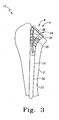
- the long bone 2, of FIG. 2 may be any long bone of the human anatomy and may, for example, be a femur, or a tibia. As shown in FIG. 2 , the long bone may be in the form of a humerus.
- the long bone 2 includes an intramedullary canal 4 extending longitudinally through the long bone 2.
- the long bone 2 may be resected and have head 5 of the long bone 2 resected along resected surface 6.
- the resection of the long bone 2 may expose the canal 4 such that a cavity 8 may be prepared in the canal 4 by the use of a drill, reamer, or a broach, or similar instrument.
- the trial stem assembly 12 may include a humeral trial stem 14 which may be fitted into cavity 8 formed in canal 4 of the long bone 2.
- the humeral trial stem 14 may include a cylindrical distal stem 30 and a proximal body 36 extending proximally from the cylindrical distal stem 30.
- the distal stem 30 may alternately include longitudinal spaced apart flutes (not shown) to assist in the securing of the humeral trial stem 14 in the canal 4 of the long bone 2.
- the humeral trial stem 14 may further include a cavity 34 formed in the proximal body 36 of the humeral trial stem 14.
- the cavity 34 may define a concave surface, or pocket, 38 for receiving the ball-cylinder 16 of the trial stem assembly 12.
- the proximal body 36 may include broach teeth 35 for broaching the canal 4 of the long bone 2.
- the broach teeth 35 may serve to eliminate the need for a separate broaching step in the arthroplasty procedure. It should be appreciated that a separate broach may be utilized with the invention of the present invention. Also it should be appreciated that the humeral trial stem 14 may also be provided without the broach teeth.
- the trial stem assembly 12 is shown in an exploded view with the distal stem component 12, the proximal neck component 16, and the fastener 18 shown as separate components in their position to be assembled to form the trial stem assembly 12.
- the proximal neck component 16 may, as is shown in FIG. 4 , be in the form of an intermediate component, or a ball-cylinder component, and may be a part of, for example, the humeral trial stem assembly 12 for use in shoulder orthopedic arthroplasty surgery.
- the proximal neck component 16 may include a feature to make the proximal neck component 16 moveable with respect to the stem 14.
- the fastener 18 may be utilized for securing the proximal neck component 16 to the stem 14.
- the proximal neck component as shown in FIG. 4 , may include a resilient portion 40 of the proximal neck component 16.
- the resilient portion 40 may be cooperative with a distal end 42 of the fastener 18.
- the proximal neck component 16 may further include a longitudinal opening 44 extending longitudinally through the proximal neck component 16.
- the longitudinal opening 44 may define internal threads 46 formed on the proximal neck component extending outwardly from the longitudinal opening 44.
- the distal stem component 12 includes the seat, or concave surface, 38 for receiving the resilient portion 40 of the proximal neck component 16.
- the fastener 18 may include external threads 48 formed on a proximal portion 49 of the fastener 18.
- the external threads 48 of the fastener 18 may be threadably engageable with the internal threads 46 formed on the proximal neck component 16.
- the proximal neck component 16 includes the proximal cylindrical portion 50 including surface 52 which may be generally cylindrical and defined by diameter ND. Alternatively, the portion 50 may be frustoconical or have a taper defined by, for example, an included angle.
- the humeral neck component 16 may further include the resilient portion 40 which may include a plurality of spaced apart fingers having longitudinal slots 54 positioned between the fingers of the resilient portion 40.
- the resilient portion 40 may include a convex external surface 56 which may be generally spherical or approximate a sphere for cooperation with the concave surface 55 of the seat 38.
- the cylindrical portion 50 of the proximal neck component 16 includes an orientation feature or key in the form of notch 51.
- the notch 51 cooperates with a feature on the trial head to provide angular orientation of the trial head with respect to the proximal neck component 16.
- the notch 51 may be a rectangular notch through a wall of the cylindrical portion 50 and extending a distance NH from the proximal end of the cylindrical portion 50.
- the notch 51 may have a width NW.
- the feature or notch 51 may have an oval, cylindrical or other shape.
- the feature 51 may be a positive feature in the form of a protrusion or other shape. In such case the humeral head would have a void to match the positive feature.
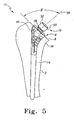
- the trial stem assembly 12 is shown in an assembled condition.
- the distal stem component 14 is shown in position in cavity 8 of the long bone 2.
- the proximal neck component 16 is assembled to stem 14 with the centerline 58 of the neck component 16 at an angle ⁇ with respect to resected surface 6 of the long bone 2.
- the center line 58 of the proximal neck component 16 is preferably normal, or perpendicular, to the resected surface 6 such that the articulating trial component 20 may properly seat against, or be positioned with respect to the resected surface 6 of the long bone 2.
- a humeral implant assembly 71 is shown.
- the humeral implant assembly 71 is utilized in shoulder joint arthroplasty in conjunction with the kit 10 of FIG. 1 including the humeral trial stem assembly 12.
- the humeral implant assembly 71 is utilized after the trial reduction is performed. If the trial reduction is successful.
- the size and orientation of the trial assembly 12 is replicated, for example, in the surgery room and the humeral implant assembly 71 is oriented to the same angles and orientation as the successful trial assembly.
- the humeral implant assembly 71 includes a solid neck stem or connector 73.
- the connector 73 includes a spherical end 75 that fits into a tapered cavity 77 of humeral implant distal stem 79 at the selected angle.
- the connector 73 includes a male taper 81 that mates with a female taper 83 on implant humeral head 85.
- the humeral articulating component for use in this invention may be concave rather than convex.
- the glenoid component is convex rather than concave.
- An example of such a product is that sold by DePuy Orthopaedics Inc under the trade mark Delta.
- the articulating trial component 20 is shown in greater detail.
- the articulating trial component 20, as shown in FIG. 7 may be a symmetrical component. It should be appreciated that the articulating trial component 20 may also be eccentric. Such an eccentric trial component is shown in FIG. 14 herein.
- the articulating trial component 20, as shown in FIGS. 6 and 7 is in the form of humeral trial head.
- the articulating trial component 20 is adapted to be removeably fixedly secured to the proximal neck component 16 of the trial stem assembly 12, of FIG. 1 .
- the articulating trial component 20 includes an articulating surface 60 and an opposed surface 62. The opposed surface 62 is opposed to the articulating surface 60.
- the articulating trial component 20 defines a longitudinal opening 64 extending from the articulating surface 60 to the opposed surface 62. It should be appreciated that the tool in the form of the driver 22, of the kit 10, may be easily passed through the longitudinal opening 64 of the articulation trial component 20.
- the longitudinal opening 64 may, as shown in FIG. 6 , be centrally located with respect to the longitudinal axis 66 of the articulating trial component 20.
- the articulating trial component 20 may, as shown in FIG. 6 , include a second cavity 68 defined by internal wall 69 formed in the articulating surface 60 of the articulating trial component 20.
- the articulating trial component 20 may further include an internal connection 65 in the form of, for example an opening, centrally located along the longitudinal center line 66 of the articulating trial component 20.
- the internal connection 65 of the articulating trial component 20 may be cylindrical and may be defined by, for example, diameter DH to mate diameter ND of proximal neck component 16. The fit between the articulating trial component 20 and the proximal neck component 16 should be sufficient for successful trialing, but loose enough to assure easy disassembly after trialing.
- the internal connection of the articulating trial component may be tapered and be defined by an included angle which is preferably similar to the included angle of the surface of tapered proximal neck component, such that the surface of the neck component may form a rigid connection with the internal tapered connection of the articulating trial component.
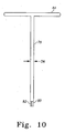
- the handle 24 of the kit 10, of FIG. 1 is shown in position on humeral prosthesis 11.
- the humeral prosthesis 11 includes the trial stem assembly 12 together with the articulating trial component 20.
- the handle 24 is advanced in the direction of the center line 66 of the articulating trial component 20 and rotated such that the central internal opening 64 and the cavity 70 of the articulating trial component 20 align with second feature 28 formed on the shaft 74, of the handle 24.
- the handle 24, as shown in FIG. 8 preferably includes a gripping portion 76 that has a shape designed to resist torque.
- the gripping portion 76 may have a shape other than a cylinder shape such that torque may be more easily resisted.
- the gripping portion 76 may have a rectangular cross-section defined by a thickness HT and a width HW.
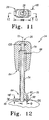
- the second feature 28 formed on the shaft 74 of the handle 24 is shown engaged with the central cavity 64 and the second cavity 70 formed into articulating surface 60 of the articulating trial component 20.
- the handle 24 is shown in position in use with the driver 22 and the trial stem assembly 12 to secure the articulating trial component 20 to the trial stem assembly 12.
- the trial stem assembly 12 includes distal stem 14 which includes a seat 38 which mates with resilient portion 40 of the proximal neck component 16 to selectably lock the neck component 16 and the articulating trial component 20 to the distal stem 14.
- the handle 24 is advanced in the direction of arrow 94 until the first member 88 fits within first opening 64 of articulating trial component 20.
- the second member 90 is fitted into second cavity 70 formed in the articulating trial component 20.
- the driver 22 may be kept in position the longitudinal opening 26 of the handle 24, or stored separately until needed. Once the driver 22 is in position the handle 24, the driver 22 is advanced in the direction of arrow 94 until the tip or bit 80 of the driver 22 engages fitting or socket 82 formed in the fastener 18. The driver 22 is rotated in the direction of arrow 96 until the distal end 42 of the fastener 18 extends toward the convex portion or resilient portion 40 of the proximal neck component 16 and advances the resilient portion radially outwardly. The convex surface 56 then engages the seat 38 of the distal stem, thereby securing the proximal neck component 16 in a proper position.
- the surgeon may hold the handle 24 in the proper position with one hand while rotating the driver 22 in the direction of arrow 96 at the same time so that the articulating trial component 20 may be placed in the proper position and so that the handle 24 may resist any torque applied by the driver 22 to either the trial stem assembly 12 or the articulating trial component 20.
- the trial stem assembly 12 includes the distal stem 14 into which the proximal neck component 16 may be pivotally positioned.
- the fastener 18 is utilized to secure the proximal neck component 16 to the distal stem 14.
- the eccentric articulating trial component 120 includes an internal connection 165 which is similar in size and shape to the internal connection 65 of the articulating trial component 20, of FIG. 6 . Therefore, the eccentric articulating trial component 120 may matingly fit to the surface 52 of the proximal neck component 16.
- the eccentric articulating trial component 120 may have its center line 163 moved around the center line 166 of the internal connection 165 of the eccentric articulating trial component 120. Therefore, it should be appreciated that the handle 24 may be utilized to orient the eccentric articulating trial component 120 in one of various positions around the center line 166 of the internal connection 165 of the eccentric articulating trial component 120.
- the handle 24 includes the first member 88 that may fit into first longitudinal opening 164 of the eccentric articulating trial component 120 as well as the second member 90 which may be fitted into second cavity 170 formed in eccentric articulating trial component 120 of the trial assembly 12.
- the eccentric articulating trial component 120 may be compatible with the trial stem assembly 12 of FIGS. 2 to 8 .
- the trial stem assembly 12 may include the distal stem 16 to which the proximal neck component 16 may be pivotally secured by, for example, screw or fastener 18.
Landscapes
- Health & Medical Sciences (AREA)
- Transplantation (AREA)
- Orthopedic Medicine & Surgery (AREA)
- Heart & Thoracic Surgery (AREA)
- Cardiology (AREA)
- Oral & Maxillofacial Surgery (AREA)
- Engineering & Computer Science (AREA)
- Biomedical Technology (AREA)
- Physical Education & Sports Medicine (AREA)
- Vascular Medicine (AREA)
- Life Sciences & Earth Sciences (AREA)
- Animal Behavior & Ethology (AREA)
- General Health & Medical Sciences (AREA)
- Public Health (AREA)
- Veterinary Medicine (AREA)
- Prostheses (AREA)
Claims (18)
- Anordnung zur Durchführung einer Probereposition bei einer Gelenkersatzoperation unter Verwendung einer Probeschaftanordnung (12; 198) mit einer ersten Komponente (14) und einer zweiten Komponente (16), die durch ein Befestigungsmittel (18) verbunden sind, und mit einer Gelenkprobekomponente (20; 120), wobei die Werkzeuganordnung umfasst:einen Treiber (22) zum Zusammenwirken mit dem Befestigungsmittel (18), um die erste Komponente (14) an der zweiten Komponente (16) zu sichern, undeinen Handgriff (24), wobei der Handgriff ein erstes Merkmal (26), um dem Treiber (22) zu ermöglichen, durch den Handgriff (24) zu treten, und ein zweites Merkmal (28) zum Verbinden des Handgriffes (24) mit der Gelenkprobekomponente (20; 120) aufweist, wobei der Handgriff (24) eine Längsachse (72) desselben definiert, dadurch gekennzeichnet, dass das zweite Merkmal (28) des Handgriffes (24) ein erstes Element (88), das sich von einem Ende des Handgriffes (24) entlang der Längsachse (72) des Handgriffes (24) erstreckt, und ein zweites Element (90) umfasst, das im Abstand von und parallel zu dem ersten Element (88) angeordnet ist.
- Werkzeuganordnung nach Anspruch 1, wobei die erste Komponente (14) der Probeschaftanordnung (12; 198) an der zweiten Komponente (16) der Probeschaftanordnung (12; 198) schwenkbar gesichert ist.
- Werkzeuganordnung nach Anspruch 1, wobei die Gelenkprobekomponente (20; 120) eine Gelenkfläche aufweist, wobei die Gelenkfläche konvex oder konkav ist.
- Werkzeuganordnung nach Anspruch 3, wobei die Gelenkfläche eine stumpfe Kugel ist.
- Werkzeuganordnung nach Anspruch 1, wobei die Probeschaftanordnung (12; 198) eine Humerusprobeschaftanordnung ist und wobei die Gelenkprobekomponente (20; 120) ein Humeruskopf ist.
- Werkzeuganordnung nach Anspruch 1, wobei die erste Komponente (14) der Humerusprobeschaftanordnung einen Humerusprobeschaft mit einer konkaven Fläche (55) umfasst, die einen Hohlraum in dem Humerusprobeschaft definiert, und wobei die zweite Komponente (16) der Humerusprobeschaftanordnung einen Humerusprobehals mit einem konkaven Abschnitt (56) zum Zusammenwirken mit der konkaven Fläche (55) des Humerusprobeschaftes und einem Schaft zum Zusammenwirken mit der Gelenkprobekomponente (20; 120) umfasst.
- Werkzeuganordnung nach Anspruch 1, wobei das erste Merkmal (26) des Handgriffes (24) eine Innenwand in dem Handgriff (24) umfasst, die eine längliche Öffnung durch den Handgriff (24) definiert.
- Werkzeuganordnung nach Anspruch 1, wobei das erste Element (88) und das zweite Element (90) eine zylindrische Gestalt aufweisen.
- Werkzeuganordnung nach Anspruch 1, wobei die Gelenkprobekomponente (20; 120) eine erste Innenwand, die einen ersten Hohlraum (64; 164) zur Aufnahme des ersten Elements (88) des zweiten Merkmals (28) des Handgriffes (24) definiert, und eine zweite Innenwand aufweist, die einen zweiten Hohlraum (70; 170) zur Aufnahme des zweiten Elements (80) des zweiten Merkmals (28) des Handgriffes (24) definiert.
- Kit (10) zur Durchführung einer Probereposition bei einer Gelenkersatzoperation, wobei das Kit umfasst:eine Probeschaftanordnung (12; 198), die eine erste Komponente (14), eine zweite Komponente (16), die in Bezug auf die erste Komponente (14) wählbar beweglich ist, und ein Befestigungsmittel (18) zum Sichern der ersten Komponente (14) an der zweiten Komponente (16) enthält;eine Gelenkprobekomponente (20; 120), die an der Probeschaftanordnung (12; 198) lösbar fest gesichert ist; undeine Werkzeuganordnung nach Anspruch 1.
- Kit (10) nach Anspruch 10, wobei die erste Komponente (14) der Probeschaftanordnung (12; 198) an der zweiten Komponente (16) der Probeschaftanordnung (12; 198) schwenkbar gesichert ist.
- Kit (10) nach Anspruch 10, wobei die Gelenkprobekomponente (20; 120) eine Gelenkfläche aufweist, wobei die Gelenkfläche konkav oder konvex ist.
- Kit (10) nach Anspruch 12, wobei die Gelenkfläche eine stumpfe Kugel ist.
- Kit (10) nach Anspruch 10, wobei die Probeschaftanordnung (12; 198) eine Humerusprobeschaftanordnung ist und wobei die Gelenkprobekomponente (20; 120) ein Humeruskopf ist.
- Kit (10) nach Anspruch 10, wobei die erste Komponente (14) der Humerusprobeschaftanordnung einen Humerusprobeschaft mit einer konkaven Fläche (55) umfasst, die einen Hohlraum in dem Humerusprobeschaft definiert, und wobei die zweite Komponente (16) der Humerusprobeschaftanordnung einen Humerusprobehals mit einem konvexen Abschnitt (56) zum Zusammenwirken mit der konkaven Fläche (55) des Humerusprobeschaftes und mit einem Schaft zum Zusammenwirken mit der Gelenkprobekomponente (20; 120) umfasst.
- Kit (10) nach Anspruch 10, wobei das erste Merkmal (26) des Handgriffes (24) eine Innenwand in dem Handgriff (24) umfasst, die eine Längsöffnung durch den Handgriff (24) definiert.
- Kit (10) nach Anspruch 10, wobei das erste Element (88) und das zweite Element (90) eine zylindrische Gestalt aufweisen.
- Kit (10) nach Anspruch 10, wobei die Gelenkprobekomponente (20; 120) umfasst:eine erste Innenwand, die einen ersten Hohlraum (64; 164) zur Aufnahme des ersten Elements (88) des zweiten Merkmals (28) des Handgriffes (24) definiert;eine zweite Innenwand, die einen zweiten Hohlraum (70; 170) zur Aufnahme des zweiten Elements (90) des zweiten Merkmals (28) des Handgriffes (24) definiert.
Applications Claiming Priority (1)
| Application Number | Priority Date | Filing Date | Title |
|---|---|---|---|
| US11/529,887 US8945138B2 (en) | 2006-09-29 | 2006-09-29 | Instrument for modular orthopaedic prosthesis |
Publications (2)
| Publication Number | Publication Date |
|---|---|
| EP1905397A1 EP1905397A1 (de) | 2008-04-02 |
| EP1905397B1 true EP1905397B1 (de) | 2011-11-16 |
Family
ID=38858904
Family Applications (1)
| Application Number | Title | Priority Date | Filing Date |
|---|---|---|---|
| EP07253854A Active EP1905397B1 (de) | 2006-09-29 | 2007-09-27 | Instrumentenkit für eine modulare orthopädische Prothese |
Country Status (3)
| Country | Link |
|---|---|
| US (1) | US8945138B2 (de) |
| EP (1) | EP1905397B1 (de) |
| AT (1) | ATE533447T1 (de) |
Cited By (1)
| Publication number | Priority date | Publication date | Assignee | Title |
|---|---|---|---|---|
| US9918854B2 (en) | 2011-03-16 | 2018-03-20 | Smith & Nephew, Inc. | Compound angle implant |
Families Citing this family (14)
| Publication number | Priority date | Publication date | Assignee | Title |
|---|---|---|---|---|
| USD598096S1 (en) * | 2009-03-13 | 2009-08-11 | Orthopedic Development Corporation | Surgical broach |
| US9084688B2 (en) * | 2009-05-19 | 2015-07-21 | DePuy Synthes Products, Inc. | Dynamic trial implants |
| US9681960B2 (en) | 2014-05-16 | 2017-06-20 | Howmedica Osteonics Corp. | Guides for fracture system |
| US10575968B2 (en) | 2014-05-16 | 2020-03-03 | Howmedica Osteonics Corp. | Guides for fracture system |
| US11129719B2 (en) | 2018-03-05 | 2021-09-28 | Synthes Gmbh | Trial radial head implant |
| US11813166B2 (en) | 2018-03-05 | 2023-11-14 | Synthes Gmbh | Trial radial head implant |
| US10813769B2 (en) | 2018-07-24 | 2020-10-27 | DePuy Synthes Products, Inc. | Baseplate of a modular shoulder joint prosthesis and related methods for implanting the same |
| EP4025160B1 (de) | 2019-09-04 | 2025-08-13 | Synthes GmbH | Radialkopfimplantat für studienzwecke |
| AU2020346827B2 (en) | 2019-09-12 | 2026-03-12 | Relievant Medsystems, Inc. | Systems and methods for tissue modulation |
| US11678993B2 (en) | 2020-02-19 | 2023-06-20 | Howmedica Osteonics Corp. | Humeral head trial with flexure |
| US12290443B2 (en) | 2020-05-01 | 2025-05-06 | Ensemble Orthopedics, Inc. | Implantable interpositional orthopedic pain management |
| US11642226B2 (en) * | 2020-05-01 | 2023-05-09 | Ensemble Orthopedics, Inc. | Implantable interpositional orthopedic pain management |
| AU2021306313A1 (en) | 2020-07-10 | 2023-03-02 | Relievant Medsystems, Inc. | Vertebral denervation in conjunction with vertebral fusion |
| US12011356B2 (en) * | 2021-05-17 | 2024-06-18 | Howmedica Osteonics Corp. | Humeral head and cup trial with flexure |
Family Cites Families (16)
| Publication number | Priority date | Publication date | Assignee | Title |
|---|---|---|---|---|
| US4003095A (en) * | 1976-04-29 | 1977-01-18 | Howmedica, Inc. | Trispherical prosthetic shoulder device |
| EP0257359B1 (de) * | 1986-08-15 | 1991-11-27 | Boehringer Mannheim Corporation | Baukastensystem für Hüftgelenksprothese |
| FR2727002B1 (fr) * | 1994-11-18 | 1997-01-03 | Tornier Sa | Prothese humerale a sphere |
| FR2727857B1 (fr) * | 1994-12-08 | 1997-01-24 | Cedior | Prothese totale d'epaule |
| DE29606468U1 (de) * | 1996-04-09 | 1997-08-07 | Waldemar Link GmbH & Co, 22339 Hamburg | Wirbelsäulenfixateur |
| FR2750037B1 (fr) * | 1996-06-25 | 1998-11-27 | Tornier Sa | Prothese d'epaule monobloc |
| FR2773469B1 (fr) * | 1998-01-09 | 2000-03-03 | Alain Leonard | Equipement chirurgical pour l'implantation d'une prothese totale d'epaule, et prothese totale d'epaule constitutive |
| ATE261707T1 (de) * | 1998-01-16 | 2004-04-15 | Ct Pulse Orthopedics Ltd | Baukasten für schaftprothesen |
| EP0940126A1 (de) | 1998-03-03 | 1999-09-08 | Lieven De Wilde | Modulare Gelenkprothese |
| US6283999B1 (en) * | 1999-01-29 | 2001-09-04 | Depuy Orthopaedics, Inc. | Shoulder prothesis with humeral fracture stem |
| AU2001257443A1 (en) * | 2000-05-03 | 2001-11-12 | Smith And Nephew, Inc. | Multi modular trialing system and instrumentation |
| US6620197B2 (en) * | 2001-01-23 | 2003-09-16 | Depuy Orthopaedics, Inc. | Method and apparatus for performing a shoulder replacement procedure in the treatment of cuff tear arthropathy |
| US6736851B2 (en) * | 2002-06-28 | 2004-05-18 | Depuy Orthopaedics, Inc. | Modular shoulder prosthesis |
| US20040010261A1 (en) * | 2002-07-12 | 2004-01-15 | Hoag Stephen H. | Tool for releasably gripping an orthopedic implant |
| US6776799B2 (en) * | 2002-09-30 | 2004-08-17 | Depuy Products, Inc. | Method and apparatus for replication of angular position of a humeral head of a shoulder prosthesis |
| US7854737B2 (en) * | 2002-12-20 | 2010-12-21 | Depuy Products, Inc. | Instrument and associated method of trailing for modular hip stems |
-
2006
- 2006-09-29 US US11/529,887 patent/US8945138B2/en active Active
-
2007
- 2007-09-27 AT AT07253854T patent/ATE533447T1/de active
- 2007-09-27 EP EP07253854A patent/EP1905397B1/de active Active
Cited By (1)
| Publication number | Priority date | Publication date | Assignee | Title |
|---|---|---|---|---|
| US9918854B2 (en) | 2011-03-16 | 2018-03-20 | Smith & Nephew, Inc. | Compound angle implant |
Also Published As
| Publication number | Publication date |
|---|---|
| ATE533447T1 (de) | 2011-12-15 |
| US20080161823A1 (en) | 2008-07-03 |
| US8945138B2 (en) | 2015-02-03 |
| EP1905397A1 (de) | 2008-04-02 |
Similar Documents
| Publication | Publication Date | Title |
|---|---|---|
| EP1905397B1 (de) | Instrumentenkit für eine modulare orthopädische Prothese | |
| US12268400B2 (en) | Combination device for use in preparing a bone to receive a prosthetic component | |
| US10945851B2 (en) | Elbow prosthesis | |
| EP1437107B1 (de) | Vorrichtung zum Ausrichten modularer Implantate | |
| US8092466B2 (en) | Expandable reverse shoulder trial | |
| US8657828B2 (en) | Humeral rotating burr guide | |
| US6702824B2 (en) | Prosthesis positioning apparatus | |
| US6875237B2 (en) | Driving instrument with variably angled joint and extended tip and method of use for minimally invasive hip surgery | |
| US8372154B2 (en) | Method and apparatus for wrist arthroplasty | |
| EP2856974A1 (de) | Distale Reibahle | |
| EP2116199B1 (de) | Instrument zur Führung der Resektion eines großen Tuberkels | |
| EP2623050B1 (de) | Instrument für die Verwendung bei der Schulterarthroplastie | |
| WO2025189029A1 (en) | Arthroplasty devices, systems, instruments, and methods |
Legal Events
| Date | Code | Title | Description |
|---|---|---|---|
| PUAI | Public reference made under article 153(3) epc to a published international application that has entered the european phase |
Free format text: ORIGINAL CODE: 0009012 |
|
| AK | Designated contracting states |
Kind code of ref document: A1 Designated state(s): AT BE BG CH CY CZ DE DK EE ES FI FR GB GR HU IE IS IT LI LT LU LV MC MT NL PL PT RO SE SI SK TR |
|
| AX | Request for extension of the european patent |
Extension state: AL BA HR MK YU |
|
| 17P | Request for examination filed |
Effective date: 20080902 |
|
| 17Q | First examination report despatched |
Effective date: 20081008 |
|
| AKX | Designation fees paid |
Designated state(s): AT BE BG CH CY CZ DE DK EE ES FI FR GB GR HU IE IS IT LI LT LU LV MC MT NL PL PT RO SE SI SK TR |
|
| GRAP | Despatch of communication of intention to grant a patent |
Free format text: ORIGINAL CODE: EPIDOSNIGR1 |
|
| GRAS | Grant fee paid |
Free format text: ORIGINAL CODE: EPIDOSNIGR3 |
|
| GRAA | (expected) grant |
Free format text: ORIGINAL CODE: 0009210 |
|
| AK | Designated contracting states |
Kind code of ref document: B1 Designated state(s): AT BE BG CH CY CZ DE DK EE ES FI FR GB GR HU IE IS IT LI LT LU LV MC MT NL PL PT RO SE SI SK TR |
|
| REG | Reference to a national code |
Ref country code: GB Ref legal event code: FG4D |
|
| REG | Reference to a national code |
Ref country code: CH Ref legal event code: EP Ref country code: CH Ref legal event code: NV Representative=s name: E. BLUM & CO. AG PATENT- UND MARKENANWAELTE VSP |
|
| REG | Reference to a national code |
Ref country code: IE Ref legal event code: FG4D |
|
| REG | Reference to a national code |
Ref country code: DE Ref legal event code: R096 Ref document number: 602007018736 Country of ref document: DE Effective date: 20120112 |
|
| REG | Reference to a national code |
Ref country code: NL Ref legal event code: VDEP Effective date: 20111116 |
|
| LTIE | Lt: invalidation of european patent or patent extension |
Effective date: 20111116 |
|
| PG25 | Lapsed in a contracting state [announced via postgrant information from national office to epo] |
Ref country code: IS Free format text: LAPSE BECAUSE OF FAILURE TO SUBMIT A TRANSLATION OF THE DESCRIPTION OR TO PAY THE FEE WITHIN THE PRESCRIBED TIME-LIMIT Effective date: 20120316 Ref country code: LT Free format text: LAPSE BECAUSE OF FAILURE TO SUBMIT A TRANSLATION OF THE DESCRIPTION OR TO PAY THE FEE WITHIN THE PRESCRIBED TIME-LIMIT Effective date: 20111116 |
|
| PG25 | Lapsed in a contracting state [announced via postgrant information from national office to epo] |
Ref country code: NL Free format text: LAPSE BECAUSE OF FAILURE TO SUBMIT A TRANSLATION OF THE DESCRIPTION OR TO PAY THE FEE WITHIN THE PRESCRIBED TIME-LIMIT Effective date: 20111116 Ref country code: BE Free format text: LAPSE BECAUSE OF FAILURE TO SUBMIT A TRANSLATION OF THE DESCRIPTION OR TO PAY THE FEE WITHIN THE PRESCRIBED TIME-LIMIT Effective date: 20111116 Ref country code: GR Free format text: LAPSE BECAUSE OF FAILURE TO SUBMIT A TRANSLATION OF THE DESCRIPTION OR TO PAY THE FEE WITHIN THE PRESCRIBED TIME-LIMIT Effective date: 20120217 Ref country code: SE Free format text: LAPSE BECAUSE OF FAILURE TO SUBMIT A TRANSLATION OF THE DESCRIPTION OR TO PAY THE FEE WITHIN THE PRESCRIBED TIME-LIMIT Effective date: 20111116 Ref country code: PT Free format text: LAPSE BECAUSE OF FAILURE TO SUBMIT A TRANSLATION OF THE DESCRIPTION OR TO PAY THE FEE WITHIN THE PRESCRIBED TIME-LIMIT Effective date: 20120316 Ref country code: LV Free format text: LAPSE BECAUSE OF FAILURE TO SUBMIT A TRANSLATION OF THE DESCRIPTION OR TO PAY THE FEE WITHIN THE PRESCRIBED TIME-LIMIT Effective date: 20111116 Ref country code: SI Free format text: LAPSE BECAUSE OF FAILURE TO SUBMIT A TRANSLATION OF THE DESCRIPTION OR TO PAY THE FEE WITHIN THE PRESCRIBED TIME-LIMIT Effective date: 20111116 Ref country code: PL Free format text: LAPSE BECAUSE OF FAILURE TO SUBMIT A TRANSLATION OF THE DESCRIPTION OR TO PAY THE FEE WITHIN THE PRESCRIBED TIME-LIMIT Effective date: 20111116 |
|
| PG25 | Lapsed in a contracting state [announced via postgrant information from national office to epo] |
Ref country code: CY Free format text: LAPSE BECAUSE OF FAILURE TO SUBMIT A TRANSLATION OF THE DESCRIPTION OR TO PAY THE FEE WITHIN THE PRESCRIBED TIME-LIMIT Effective date: 20111116 |
|
| PG25 | Lapsed in a contracting state [announced via postgrant information from national office to epo] |
Ref country code: SK Free format text: LAPSE BECAUSE OF FAILURE TO SUBMIT A TRANSLATION OF THE DESCRIPTION OR TO PAY THE FEE WITHIN THE PRESCRIBED TIME-LIMIT Effective date: 20111116 Ref country code: EE Free format text: LAPSE BECAUSE OF FAILURE TO SUBMIT A TRANSLATION OF THE DESCRIPTION OR TO PAY THE FEE WITHIN THE PRESCRIBED TIME-LIMIT Effective date: 20111116 Ref country code: DK Free format text: LAPSE BECAUSE OF FAILURE TO SUBMIT A TRANSLATION OF THE DESCRIPTION OR TO PAY THE FEE WITHIN THE PRESCRIBED TIME-LIMIT Effective date: 20111116 Ref country code: BG Free format text: LAPSE BECAUSE OF FAILURE TO SUBMIT A TRANSLATION OF THE DESCRIPTION OR TO PAY THE FEE WITHIN THE PRESCRIBED TIME-LIMIT Effective date: 20120216 Ref country code: CZ Free format text: LAPSE BECAUSE OF FAILURE TO SUBMIT A TRANSLATION OF THE DESCRIPTION OR TO PAY THE FEE WITHIN THE PRESCRIBED TIME-LIMIT Effective date: 20111116 |
|
| PG25 | Lapsed in a contracting state [announced via postgrant information from national office to epo] |
Ref country code: RO Free format text: LAPSE BECAUSE OF FAILURE TO SUBMIT A TRANSLATION OF THE DESCRIPTION OR TO PAY THE FEE WITHIN THE PRESCRIBED TIME-LIMIT Effective date: 20111116 |
|
| REG | Reference to a national code |
Ref country code: AT Ref legal event code: MK05 Ref document number: 533447 Country of ref document: AT Kind code of ref document: T Effective date: 20111116 |
|
| PLBE | No opposition filed within time limit |
Free format text: ORIGINAL CODE: 0009261 |
|
| STAA | Information on the status of an ep patent application or granted ep patent |
Free format text: STATUS: NO OPPOSITION FILED WITHIN TIME LIMIT |
|
| 26N | No opposition filed |
Effective date: 20120817 |
|
| REG | Reference to a national code |
Ref country code: DE Ref legal event code: R097 Ref document number: 602007018736 Country of ref document: DE Effective date: 20120817 |
|
| PG25 | Lapsed in a contracting state [announced via postgrant information from national office to epo] |
Ref country code: AT Free format text: LAPSE BECAUSE OF FAILURE TO SUBMIT A TRANSLATION OF THE DESCRIPTION OR TO PAY THE FEE WITHIN THE PRESCRIBED TIME-LIMIT Effective date: 20111116 |
|
| PG25 | Lapsed in a contracting state [announced via postgrant information from national office to epo] |
Ref country code: ES Free format text: LAPSE BECAUSE OF FAILURE TO SUBMIT A TRANSLATION OF THE DESCRIPTION OR TO PAY THE FEE WITHIN THE PRESCRIBED TIME-LIMIT Effective date: 20120227 Ref country code: MC Free format text: LAPSE BECAUSE OF NON-PAYMENT OF DUE FEES Effective date: 20120930 |
|
| PG25 | Lapsed in a contracting state [announced via postgrant information from national office to epo] |
Ref country code: FI Free format text: LAPSE BECAUSE OF FAILURE TO SUBMIT A TRANSLATION OF THE DESCRIPTION OR TO PAY THE FEE WITHIN THE PRESCRIBED TIME-LIMIT Effective date: 20111116 |
|
| PG25 | Lapsed in a contracting state [announced via postgrant information from national office to epo] |
Ref country code: MT Free format text: LAPSE BECAUSE OF FAILURE TO SUBMIT A TRANSLATION OF THE DESCRIPTION OR TO PAY THE FEE WITHIN THE PRESCRIBED TIME-LIMIT Effective date: 20111116 |
|
| PG25 | Lapsed in a contracting state [announced via postgrant information from national office to epo] |
Ref country code: TR Free format text: LAPSE BECAUSE OF FAILURE TO SUBMIT A TRANSLATION OF THE DESCRIPTION OR TO PAY THE FEE WITHIN THE PRESCRIBED TIME-LIMIT Effective date: 20111116 |
|
| PG25 | Lapsed in a contracting state [announced via postgrant information from national office to epo] |
Ref country code: LU Free format text: LAPSE BECAUSE OF NON-PAYMENT OF DUE FEES Effective date: 20120927 |
|
| PG25 | Lapsed in a contracting state [announced via postgrant information from national office to epo] |
Ref country code: HU Free format text: LAPSE BECAUSE OF FAILURE TO SUBMIT A TRANSLATION OF THE DESCRIPTION OR TO PAY THE FEE WITHIN THE PRESCRIBED TIME-LIMIT Effective date: 20070927 |
|
| REG | Reference to a national code |
Ref country code: FR Ref legal event code: PLFP Year of fee payment: 10 |
|
| REG | Reference to a national code |
Ref country code: FR Ref legal event code: PLFP Year of fee payment: 11 |
|
| REG | Reference to a national code |
Ref country code: FR Ref legal event code: PLFP Year of fee payment: 12 |
|
| PGFP | Annual fee paid to national office [announced via postgrant information from national office to epo] |
Ref country code: IT Payment date: 20220811 Year of fee payment: 16 Ref country code: IE Payment date: 20220809 Year of fee payment: 16 Ref country code: GB Payment date: 20220804 Year of fee payment: 16 Ref country code: DE Payment date: 20220609 Year of fee payment: 16 |
|
| PGFP | Annual fee paid to national office [announced via postgrant information from national office to epo] |
Ref country code: FR Payment date: 20220808 Year of fee payment: 16 |
|
| PGFP | Annual fee paid to national office [announced via postgrant information from national office to epo] |
Ref country code: CH Payment date: 20221001 Year of fee payment: 16 |
|
| REG | Reference to a national code |
Ref country code: DE Ref legal event code: R119 Ref document number: 602007018736 Country of ref document: DE |
|
| REG | Reference to a national code |
Ref country code: CH Ref legal event code: PL |
|
| GBPC | Gb: european patent ceased through non-payment of renewal fee |
Effective date: 20230927 |
|
| REG | Reference to a national code |
Ref country code: IE Ref legal event code: MM4A |
|
| PG25 | Lapsed in a contracting state [announced via postgrant information from national office to epo] |
Ref country code: IE Free format text: LAPSE BECAUSE OF NON-PAYMENT OF DUE FEES Effective date: 20230927 |
|
| PG25 | Lapsed in a contracting state [announced via postgrant information from national office to epo] |
Ref country code: GB Free format text: LAPSE BECAUSE OF NON-PAYMENT OF DUE FEES Effective date: 20230927 |
|
| PG25 | Lapsed in a contracting state [announced via postgrant information from national office to epo] |
Ref country code: CH Free format text: LAPSE BECAUSE OF NON-PAYMENT OF DUE FEES Effective date: 20230930 |
|
| PG25 | Lapsed in a contracting state [announced via postgrant information from national office to epo] |
Ref country code: IE Free format text: LAPSE BECAUSE OF NON-PAYMENT OF DUE FEES Effective date: 20230927 Ref country code: GB Free format text: LAPSE BECAUSE OF NON-PAYMENT OF DUE FEES Effective date: 20230927 Ref country code: FR Free format text: LAPSE BECAUSE OF NON-PAYMENT OF DUE FEES Effective date: 20230930 Ref country code: DE Free format text: LAPSE BECAUSE OF NON-PAYMENT OF DUE FEES Effective date: 20240403 Ref country code: CH Free format text: LAPSE BECAUSE OF NON-PAYMENT OF DUE FEES Effective date: 20230930 |
|
| PG25 | Lapsed in a contracting state [announced via postgrant information from national office to epo] |
Ref country code: IT Free format text: LAPSE BECAUSE OF NON-PAYMENT OF DUE FEES Effective date: 20230927 |
|
| PG25 | Lapsed in a contracting state [announced via postgrant information from national office to epo] |
Ref country code: IT Free format text: LAPSE BECAUSE OF NON-PAYMENT OF DUE FEES Effective date: 20230927 |