EP1903963B1 - Vorrichtung zur verbindung von komponenten in wirbelsäuleninstrumenten mit stangen - Google Patents
Vorrichtung zur verbindung von komponenten in wirbelsäuleninstrumenten mit stangen Download PDFInfo
- Publication number
- EP1903963B1 EP1903963B1 EP06752059A EP06752059A EP1903963B1 EP 1903963 B1 EP1903963 B1 EP 1903963B1 EP 06752059 A EP06752059 A EP 06752059A EP 06752059 A EP06752059 A EP 06752059A EP 1903963 B1 EP1903963 B1 EP 1903963B1
- Authority
- EP
- European Patent Office
- Prior art keywords
- connector body
- clamp element
- receptacle
- clamp
- passage
- Prior art date
- Legal status (The legal status is an assumption and is not a legal conclusion. Google has not performed a legal analysis and makes no representation as to the accuracy of the status listed.)
- Not-in-force
Links
Images


Classifications
-
- A—HUMAN NECESSITIES
- A61—MEDICAL OR VETERINARY SCIENCE; HYGIENE
- A61B—DIAGNOSIS; SURGERY; IDENTIFICATION
- A61B17/00—Surgical instruments, devices or methods, e.g. tourniquets
- A61B17/56—Surgical instruments or methods for treatment of bones or joints; Devices specially adapted therefor
- A61B17/58—Surgical instruments or methods for treatment of bones or joints; Devices specially adapted therefor for osteosynthesis, e.g. bone plates, screws, setting implements or the like
- A61B17/68—Internal fixation devices, including fasteners and spinal fixators, even if a part thereof projects from the skin
- A61B17/70—Spinal positioners or stabilisers ; Bone stabilisers comprising fluid filler in an implant
- A61B17/7049—Connectors, not bearing on the vertebrae, for linking longitudinal elements together
- A61B17/705—Connectors, not bearing on the vertebrae, for linking longitudinal elements together for linking adjacent ends of longitudinal elements
-
- A—HUMAN NECESSITIES
- A61—MEDICAL OR VETERINARY SCIENCE; HYGIENE
- A61B—DIAGNOSIS; SURGERY; IDENTIFICATION
- A61B17/00—Surgical instruments, devices or methods, e.g. tourniquets
- A61B17/56—Surgical instruments or methods for treatment of bones or joints; Devices specially adapted therefor
- A61B17/58—Surgical instruments or methods for treatment of bones or joints; Devices specially adapted therefor for osteosynthesis, e.g. bone plates, screws, setting implements or the like
- A61B17/68—Internal fixation devices, including fasteners and spinal fixators, even if a part thereof projects from the skin
- A61B17/70—Spinal positioners or stabilisers ; Bone stabilisers comprising fluid filler in an implant
- A61B17/7049—Connectors, not bearing on the vertebrae, for linking longitudinal elements together
Landscapes
- Health & Medical Sciences (AREA)
- Orthopedic Medicine & Surgery (AREA)
- Life Sciences & Earth Sciences (AREA)
- Neurology (AREA)
- Surgery (AREA)
- Heart & Thoracic Surgery (AREA)
- Engineering & Computer Science (AREA)
- Biomedical Technology (AREA)
- Nuclear Medicine, Radiotherapy & Molecular Imaging (AREA)
- Medical Informatics (AREA)
- Molecular Biology (AREA)
- Animal Behavior & Ethology (AREA)
- General Health & Medical Sciences (AREA)
- Public Health (AREA)
- Veterinary Medicine (AREA)
- Surgical Instruments (AREA)
- Prostheses (AREA)
Claims (21)
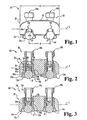
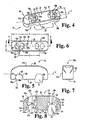
- Vorrichtung (20; 200) zur Verbindung mit einer Komponente, die in Verbindung mit einem Wirbelsäuleninstrument, wobei die Vorrichtung folgendes umfasst:einen Verbinderkörper (22; 222), der eine Aufnahmeeinrichtung (30a, 30b) definiert, die sich dort hindurch erstreckt und sich auf eine äußere Oberfläche dessen öffnet, wobei die genannte Aufnahmeeinrichtung (30a, 30b) ein Paar entgegengesetzt ausgerichteter, konischer Eingriffsoberflächen (40a, 40b) aufweist, wobei der genannte Verbinderkörper (22; 222) einen Durchgang (50a, 50b) definiert, der sich in transversaler Übertragungsverbindung mit der genannten Aufnahmeeinrichtung (30a, 30b) befindet;ein Klemmenelement (24a, 24b; 224a, 224b), das mindestens zwei Armteilstücke (72a, 72b) aufweist, die dazwischen einen Zwischenraum mit einem offenen Ende definieren, wobei das genannte Klemmenelement (24a, 24b; 224a, 224b) in dem genannten Durchgang (50a, 50b) in dem genannten Verbinderkörper (22; 222) positioniert ist, wobei der genannte Zwischenraum allgemein mit der genannten Aufnahmeeinrichtung (30a, 30b) ausgerichtet ist, und wobei die Komponente durch das genannte offene Ende und in den genannten Zwischenraum aufgenommen werden kann; undein Befestigungselement (26a, 26b; 226a, 226b);dadurch gekennzeichnet, dass das Befestigungselement (26a, 26b; 226a, 226b) mit dem genannten Klemmenelement (24a, 24b; 224a, 224b) so zusammenwirkt, dass das genannte Klemmenelement (24a, 24b; 224a, 224b) im Verhältnis zu dem genannten Verbinderkörper (22; 222) versetzt wird, für einen Eingriff der Komponente an den genannten konischen Eingriffsoberflächen (40a, 40b).
- Vorrichtung (20) nach Anspruch 1, wobei der genannte Verbinderkörper (22) und das genannte Klemmenelement (24a, 24b) Antirotationsmerkmale (66a, 66b, 84a, 84b) aufweisen, die miteinander so zusammenwirken, dass sie eine Rotation des genannten Klemmenelements innerhalb des genannten Durchgangs im Wesentlichen verhindern.
- Vorrichtung (20) nach Anspruch 1, wobei der genannte Verbinderkörper (22) eine Eingriffsoberfläche definiert, die entlang dem genannten Durchgang (50a, 50b) positioniert ist, wobei das genannte Klemmenelement (24a, 24b) ein Basisteilstück (70) aufweist, das eine Gewindeöffnung mit den genannten Armteilstücken (72a, 72b) definiert, die sich von dem genannten Basisteilstück (70) erstrecken, wobei das genannte Befestigungselement (26a, 26b) ein Gewindeteilstück (102) aufweist, das schraubfähig in der genannten Gewindeöffnung des genannten Klemmenelements (24a, 24b) eingreift, wobei das genannte Gewindeteilstück (102) eine Endoberfläche (110) aufweist, die anstoßend an die genannte Eingriffsoberfläche des genannten Verbinderkörpers (22) positioniert ist, so dass eine Rotation des genannten Befestigungselements (26a, 26b) entsprechend das genannte Klemmenelement (24a, 24b) in den genannten Verbinderkörper (22) zieht, um zumindest ein Teilstück der Komponente innerhalb der genannten Aufnahmeeinrichtung (30a, 30b) zu positionieren.
- Vorrichtung (20) nach Anspruch 3, wobei die genannte Eingriffsoberfläche durch eine innere Wand (58) definiert ist, die sich über zumindest ein Teilstück des genannten Durchgangs (50a, 50b) erstreckt.
- Vorrichtung (20) nach Anspruch 4, wobei die genannte innere Wand (58) mindestens zwei Öffnungen (56a, 56b) definiert, die für die Aufnahme entsprechender der genannten mindestens zwei Armteilstücke (72a, 72b) dort hindurch bemessen sind.
- Vorrichtung (20) nach Anspruch 3, wobei die genannte Eingriffsoberfläche definiert ist durch ein Brückenteilstück (58), das sich über den genannten Durchgang erstreckt.
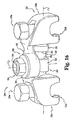
- Vorrichtung (20, 200) nach Anspruch 1, wobei die genannte Verbindervorrichtung ein erstes Empfängerteilstück (30a; 230a), ein zweites Empfängerteilstück (30b; 230b) und ein Brückenteilstück (28; 228) umfasst, das sich zwischen den genannten ersten und zweiten Empfängerteilstücken (230a, 230b) erstreckt, wobei die genannten ersten und zweiten Empfängerteilstücke (30a, 30b; 230a, 230b) jeweils einen der genannten Verbinderkörper (22; 222), einen der genannten Klemmenelemente (24a, 24b; 224a, 224b) und einen der genannten Befestigungselemente (26a, 26b; 226a, 226b) aufweisen, wobei jedes der genannten ersten und zweiten Empfängerteilstücke (30a, 30b; 230a, 230b) für eine Verbindung mit entsprechenden Wirbelsäulenstangen erster und zweiter Wirbelsäulenstangen konfiguriert ist.
- Vorrichtung (200) nach Anspruch 7, wobei das genannte Brückenteilstück (228) so konfiguriert ist, dass eine selektive Anpassung eines Abstands zwischen den genannten ersten und zweiten Wirbelsäulenstangen bereitgestellt wird.
- Vorrichtung (200) nach Anspruch 7, wobei das genannte Brückenteilstück (228) so konfiguriert ist, dass eine selektive Anpassung eines Winkels zwischen den genannten ersten und zweiten Wirbelsäulenstangen bereitgestellt wird.
- Vorrichtung (20) nach Anspruch 1, wobei das genannte Befestigungselement (26a, 26b) eine Stellschraube (100) umfasst, die ein Gewindeschaftteilstück (102) aufweist, das schraubfähig in einer Gewindeöffnung in dem genannten Klemmenelement (24a, 24b) eingreift, um das genannte Klemmenelement (24a, 24b) im Verhältnis zu dem genannten Verbinderkörper (22) zu verschieben.
- Vorrichtung nach Anspruch 10, wobei die genannte Stellschraube (100) ein Kopfteilstück (104) aufweist, das selektiv von dem genannten Gewindeschaftteilstück (102) getrennt werden kann.
- Vorrichtung (20) nach Anspruch 1, wobei:der genannte Verbinderkörper (22) und das genannte Klemmenelement (24a, 24b) Antirotationsmerkmale (66a, 66b, 84a, 84b) aufweisen, die miteinander so zusammenwirken, dass sie die Rotation des genannten Klemmenelements (24a, 24b) in dem genannten Durchgang (50a, 50b) im Wesentlichen verhindern, wobei zumindest der genannte Verbinderkörper (22) oder eines der genannten Armteilstücke (72a, 72b) des genannten Klemmenelements (24a, 24b) eine konische Region (40a, 40b, 90a, 90b) definieren; unddas Befestigungselement (26a, 26b) mit dem genannten Klemmenelement so zusammenwirkt, dass das genannte Klemmenelement (24a, 24b) im Verhältnis zu dem genannten Verbinderkörper (22) entlang der genannten konischen Region (40a, 40b, 90a, 90b) verschoben wird, um die genannten Armteilstücke (72a, 72b) um die Komponente zusammenzudrücken, um die Komponente innerhalb des genannten Zwischenraums zu halten, wobei die Komponente zumindest teilweise innerhalb der genannten Aufnahmeeinrichtung (30a, 30b) positioniert ist.
- Vorrichtung (20) nach Anspruch 2 oder Anspruch 12, wobei das genannte Klemmenelement (24a, 24b) ein oberes Teilstück aufweist, das innerhalb des genannten Durchgangs in dem genannten Verbinderkörper positioniert ist, und mit einem unteren Teilstück, das angrenzend an die genannte Aufnahmeeinrichtung (30a, 30b) positioniert ist, wobei die genannten Antirotationsmerkmale (66a, 66b, 84a, 84b) angrenzend an das genannte obere Teilstück des genannten Klemmenelements (24a, 24b) angeordnet sind.
- Vorrichtung (20) nach Anspruch 12, wobei der genannte Verbinderkörper (22) eine erste konische Region (40a, 40b) definiert, wobei die genannten Armteilstücke (72a, 72b) des genannten Klemmenelements (24a, 24b) eine zweite konische Region (90a, 90b) definieren, wobei das genannte Befestigungselement (26a, 26b) so mit dem genannten Klemmenelement (24a, 24b) zusammenwirkt, dass die genannte erste konische Region entlang der genannten zweiten konischen Region verschoben wird, um die genannten Armteilstücke (72a, 72b) um die Komponente zusammenzudrücken.
- Vorrichtung (20) nach Anspruch 1, wobei:das genannte Klemmenelement (24a, 24b) ein oberes Teilstück aufweist, das innerhalb des genannten Durchgangs (50a, 50b) in dem genannten Verbinderkörper (22) positioniert ist, und mit einem unteren Teilstück, das angrenzend an die genannte Aufnahmeeinrichtung (30a, 30b) positioniert ist, wobei der genannte Zwischenraum allgemein mit der genannten Aufnahmeeinrichtung (30a, 30b) und mit den Komponenten ausgerichtet ist, die durch das genannte offene Ende und in den genannten Zwischenraum aufgenommen werden, wobei der genannte Verbinderkörper (22) und das genannte obere Teilstück des genannten Klemmenelements (24a, 24b) Antirotationsmerkmale (66a, 66b, 84a, 84b) aufweisen, die miteinander zusammenwirken, so dass eine Rotation des genannten Klemmelements (24a, 24b) innerhalb des genannten Durchgangs (50a, 50b) im Wesentlichen verhindert wird; unddas Befestigungselement (26a, 26b) mit dem genannten Klemmenelement (24a, 24b) so zusammenwirkt, dass das genannte Klemmenelement (24a, 24b) im Verhältnis zu dem genannten Verbinderkörper (22) verschoben wird, um zumindest ein Teilstück der Komponente innerhalb der genannten Aufnahmeeinrichtung (30a, 30b) zu positionieren.
- Vorrichtung (20) nach Anspruch 15, wobei die genannten Antirotationsmerkmale (66a, 66b, 84a, 84b) einen Vorsprung (84a, 84b) umfassen, der innerhalb einer Rille (66a, 66b) positioniert ist.
- Vorrichtung (20) nach Anspruch 16, wobei sich der genannte Vorsprung (84a, 84b) entlang dem genannten oberen Teilstück des genannten Klemmenelements (24a, 24b) erstreckt, und wobei sich die genannte Rille (66a, 66b) entlang dem genannten Durchgang (50a, 50b) in dem genannten Verbinderkörper (22) erstreckt.
- Vorrichtung (20) nach Anspruch 1 oder Anspruch 5, wobei mindestens der genannte Verbinderkörper (22) oder eines der genannten Armteilstücke (72a, 72b) des genannten Klemmenelements (24a, 24b) eine konische Region (40a, 40b, 90a, 90b) definiert, wobei das genannte Befestigungselement (26a, 26b9 mit dem genannten Klemmenelement (24a, 24b) so zusammenwirkt, dass das genannte Klemmenelement (24a, 24b) im Verhältnis zu dem genannten Verbinderkörper (22) entlang der genannten konischen Region (40a, 40b, 90a, 90b) verschoben wird, um die genannten Armteilstücke (72a, 72b) um die Komponente zusammenzudrücken.
- Vorrichtung nach Anspruch 18 in Abhängigkeit von Anspruch 1, wobei die genannte konische Region nah angrenzend an die genannte Aufnahmeeinrichtung angeordnet ist.
- Vorrichtung (20) nach Anspruch 12 oder Anspruch 15, wobei der genannte Verbinderkörper eine Eingriffsoberfläche definiert, die entlang dem genannten Durchgang (50a, 50b) positioniert ist, wobei das genannte Klemmenelement (24a, 24b) ein Basisteilstück (70) aufweist, das eine Gewindeöffnung definiert, wobei sich die genannten Armteilstücke (72a, 72b) von dem genannten Basisteilstück (70) erstrecken, wobei das genannte Befestigungselement (26a, 26b) ein Gewindeteilstück (102) aufweist, das schraubfähig in der genannten Gewindeöffnung des genannten Klemmenelements (24a, 24b) eingreift, wobei das genannte Gewindeteilstück (102) eine Endoberfläche (110) aufweist, die anstoßend an die genannte Eingriffsoberfläche des genannten Verbinderkörpers (22) positioniert ist, so dass eine Rotation des genannten Befestigungselements (26a, 26b) entsprechend das genannte Klemmenelement (24a, 24b) in den genannten Verbinderkörper (22) zieht, um zumindest ein Teilstück der Komponente innerhalb der genannten Aufnahmeeinrichtung zu positionieren.
- Vorrichtung (20) nach Anspruch 20, wobei die genannte Eingriffsoberfläche definiert ist durch eine innere Wand (58), die sich über zumindest ein Teilstück des genannten Durchgangs erstreckt.
Applications Claiming Priority (2)
| Application Number | Priority Date | Filing Date | Title |
|---|---|---|---|
| US11/118,648 US7585314B2 (en) | 2005-04-29 | 2005-04-29 | Device for interconnecting components in spinal instrumentation |
| PCT/US2006/016747 WO2006119255A2 (en) | 2005-04-29 | 2006-05-01 | Device for interconnecting components in spinal instrumentation with rods |
Publications (2)
| Publication Number | Publication Date |
|---|---|
| EP1903963A2 EP1903963A2 (de) | 2008-04-02 |
| EP1903963B1 true EP1903963B1 (de) | 2012-03-14 |
Family
ID=36952648
Family Applications (1)
| Application Number | Title | Priority Date | Filing Date |
|---|---|---|---|
| EP06752059A Not-in-force EP1903963B1 (de) | 2005-04-29 | 2006-05-01 | Vorrichtung zur verbindung von komponenten in wirbelsäuleninstrumenten mit stangen |
Country Status (7)
| Country | Link |
|---|---|
| US (1) | US7585314B2 (de) |
| EP (1) | EP1903963B1 (de) |
| JP (1) | JP2009504198A (de) |
| AT (1) | ATE548981T1 (de) |
| AU (1) | AU2006242212B2 (de) |
| CA (1) | CA2605873A1 (de) |
| WO (1) | WO2006119255A2 (de) |
Families Citing this family (43)
| Publication number | Priority date | Publication date | Assignee | Title |
|---|---|---|---|---|
| US7959653B2 (en) | 2004-09-03 | 2011-06-14 | Lanx, Inc. | Spinal rod cross connector |
| US20070219556A1 (en) * | 2004-10-20 | 2007-09-20 | Moti Altarac | System and methods for posterior dynamic stabilization of the spine |
| WO2006047555A2 (en) * | 2004-10-25 | 2006-05-04 | Alphaspine, Inc. | Bone fixation systems and methods |
| AU2007204975A1 (en) * | 2006-01-10 | 2007-07-19 | Life Spine, Inc. | Pedicle screw constructs and spinal rod attachment assemblies |
| US7794478B2 (en) * | 2007-01-15 | 2010-09-14 | Innovative Delta Technology, Llc | Polyaxial cross connector and methods of use thereof |
| US9962194B2 (en) | 2007-01-15 | 2018-05-08 | Innovative Delta Technology, Llc | Polyaxial spinal stabilizer connector and methods of use thereof |
| US9237954B2 (en) * | 2007-03-29 | 2016-01-19 | Life Spine, Inc. | Height adjustable spinal prostheses |
| US8337527B2 (en) * | 2007-04-18 | 2012-12-25 | Ebi, Llc | Spinal connector |
| US9204908B2 (en) | 2007-07-26 | 2015-12-08 | Dynamic Spine, Llc | Segmental orthopedic device for spinal elongation and for treatment of scoliosis |
| EP2182871B1 (de) * | 2007-07-26 | 2014-07-02 | Glenn R. Buttermann M. D. | Segmentale orthopädische vorrichtung zur streckung der wirbelsäule und zur behandlung von skoliose |
| US9579126B2 (en) | 2008-02-02 | 2017-02-28 | Globus Medical, Inc. | Spinal rod link reducer |
| CN102046107B (zh) | 2008-04-21 | 2014-10-01 | 整连中心有限责任公司 | 后脊柱紧固器 |
| US20100004693A1 (en) * | 2008-07-01 | 2010-01-07 | Peter Thomas Miller | Cam locking spine stabilization system and method |
| US8118837B2 (en) | 2008-07-03 | 2012-02-21 | Zimmer Spine, Inc. | Tapered-lock spinal rod connectors and methods for use |
| US8197512B1 (en) | 2008-07-16 | 2012-06-12 | Zimmer Spine, Inc. | System and method for spine stabilization using resilient inserts |
| US8167914B1 (en) | 2008-07-16 | 2012-05-01 | Zimmer Spine, Inc. | Locking insert for spine stabilization and method of use |
| US8951289B2 (en) * | 2008-10-09 | 2015-02-10 | Total Connect Spine, Llc | Spinal connection assembly |
| BRPI0919600A2 (pt) * | 2008-12-17 | 2015-12-08 | Synthes Gmbh | estabilizador espinhal posterior e dinâmico |
| US8998961B1 (en) | 2009-02-26 | 2015-04-07 | Lanx, Inc. | Spinal rod connector and methods |
| CA2759249A1 (en) | 2009-04-23 | 2010-10-28 | Spinal Elements, Inc. | Transverse connectors |
| KR101000892B1 (ko) * | 2009-05-04 | 2010-12-13 | (주)엘앤케이바이오메드 | 척추로드 연결용 측방 클릭 커넥터장치 |
| EP2467076B1 (de) | 2009-08-21 | 2018-09-19 | K2M, Inc. | Transversaler stangenverbinder |
| WO2011069963A2 (de) * | 2009-12-10 | 2011-06-16 | Kilian Kraus | Stabverbinder |
| AU2011264818B2 (en) | 2010-06-10 | 2015-06-18 | Globus Medical, Inc. | Low-profile, uniplanar bone screw |
| US8920471B2 (en) | 2010-07-12 | 2014-12-30 | K2M, Inc. | Transverse connector |
| EP2471476A1 (de) * | 2010-11-10 | 2012-07-04 | Zimmer Spine | Knochenanker |
| US8758411B1 (en) | 2011-10-25 | 2014-06-24 | Nuvasive, Inc. | Implants and methods for treating spinal disorders |
| US8808328B2 (en) * | 2012-04-05 | 2014-08-19 | Tufts Medical Center, Inc. | Spring loaded mechanism for managing scoliosis |
| US9510866B2 (en) | 2012-08-15 | 2016-12-06 | Blackstone Medical, Inc. | Pivoting spinal fixation devices |
| US10624679B2 (en) | 2016-03-29 | 2020-04-21 | Globus Medical, Inc. | Revision connectors, systems and methods thereof |
| US10820929B2 (en) | 2016-03-29 | 2020-11-03 | Globus Medical Inc. | Revision connectors, systems, and methods thereof |
| US10307185B2 (en) | 2016-03-29 | 2019-06-04 | Globus Medical, Inc. | Revision connectors, systems, and methods thereof |
| US10383663B2 (en) | 2016-03-29 | 2019-08-20 | Globus Medical, Inc. | Revision connectors, systems and methods thereof |
| US10517647B2 (en) | 2016-05-18 | 2019-12-31 | Medos International Sarl | Implant connectors and related methods |
| US10321939B2 (en) | 2016-05-18 | 2019-06-18 | Medos International Sarl | Implant connectors and related methods |
| US10398476B2 (en) | 2016-12-13 | 2019-09-03 | Medos International Sàrl | Implant adapters and related methods |
| US10492835B2 (en) | 2016-12-19 | 2019-12-03 | Medos International Sàrl | Offset rods, offset rod connectors, and related methods |
| US10238432B2 (en) | 2017-02-10 | 2019-03-26 | Medos International Sàrl | Tandem rod connectors and related methods |
| US10966761B2 (en) | 2017-03-28 | 2021-04-06 | Medos International Sarl | Articulating implant connectors and related methods |
| US10561454B2 (en) | 2017-03-28 | 2020-02-18 | Medos International Sarl | Articulating implant connectors and related methods |
| US11076890B2 (en) | 2017-12-01 | 2021-08-03 | Medos International Sàrl | Rod-to-rod connectors having robust rod closure mechanisms and related methods |
| US11653956B2 (en) * | 2018-11-14 | 2023-05-23 | Quandary Medical, Llc | Cross connection system for strengthening a stabilization construct |
| US11331125B1 (en) * | 2021-10-07 | 2022-05-17 | Ortho Inventions, Llc | Low profile rod-to-rod coupler |
Family Cites Families (30)
| Publication number | Priority date | Publication date | Assignee | Title |
|---|---|---|---|---|
| US4471159A (en) * | 1982-05-24 | 1984-09-11 | Burndy Corporation | Electrical connector and method of making an electrical connection |
| US4764131A (en) * | 1987-07-13 | 1988-08-16 | Amp Incorporated | Electrical connector |
| CH683963A5 (de) * | 1988-06-10 | 1994-06-30 | Synthes Ag | Fixateur intern. |
| FR2658414B1 (fr) * | 1990-02-19 | 1992-07-31 | Sofamor | Implant pour dispositif d'osteosynthese en particulier du rachis. |
| US5281222A (en) * | 1992-06-30 | 1994-01-25 | Zimmer, Inc. | Spinal implant system |
| US5312405A (en) * | 1992-07-06 | 1994-05-17 | Zimmer, Inc. | Spinal rod coupler |
| FR2697992B1 (fr) * | 1992-11-18 | 1994-12-30 | Eurosurgical | Dispositif de fixation sur une tige d'un organe, en particulier pour une instrumentation d'orthopédie rachidienne. |
| US5330473A (en) * | 1993-03-04 | 1994-07-19 | Advanced Spine Fixation Systems, Inc. | Branch connector for spinal fixation systems |
| JP3403231B2 (ja) * | 1993-05-12 | 2003-05-06 | 三菱電機株式会社 | 半導体装置およびその製造方法 |
| US6077262A (en) * | 1993-06-04 | 2000-06-20 | Synthes (U.S.A.) | Posterior spinal implant |
| DE4331178A1 (de) * | 1993-09-14 | 1995-03-16 | Hoechst Schering Agrevo Gmbh | Substituierte Pyridine und Pyrimidine, Verfahren zu ihrer Herstellung und ihre Verwendung als Schädlingsbekämpfungsmittel und Fungizide |
| EP0874594B1 (de) | 1995-06-06 | 2003-10-08 | SDGI Holdings, Inc. | Vorrichtung zum verbinden von benachbarten wirbelsäulenstützstäben |
| FR2742040B1 (fr) * | 1995-12-07 | 1998-01-23 | Groupe Lepine | Dispositif d'assemblage pour pieces allongees de materiel d'osteosynthese, notamment rachidienne |
| US5709685A (en) * | 1996-05-21 | 1998-01-20 | Sdgi Holdings, Inc. | Positionable clip for provisionally capturing a component on a spinal rod |
| US6171311B1 (en) * | 1996-10-18 | 2001-01-09 | Marc Richelsoph | Transverse connector |
| US6416515B1 (en) * | 1996-10-24 | 2002-07-09 | Spinal Concepts, Inc. | Spinal fixation system |
| EP0934026B1 (de) * | 1996-10-24 | 2009-07-15 | Zimmer Spine Austin, Inc | Gerät zur Fixation der Wirbelsäule |
| US6485494B1 (en) * | 1996-12-20 | 2002-11-26 | Thomas T. Haider | Pedicle screw system for osteosynthesis |
| US5810819A (en) * | 1997-05-15 | 1998-09-22 | Spinal Concepts, Inc. | Polyaxial pedicle screw having a compression locking rod gripping mechanism |
| AU3764597A (en) * | 1997-08-21 | 1999-03-16 | Synthes Ag, Chur | Device for connecting a rod to another implant |
| FR2771918B1 (fr) * | 1997-12-09 | 2000-04-21 | Dimso Sa | Connecteur pour dispositif d'osteosynthese rachidienne |
| FR2781663B1 (fr) * | 1998-07-30 | 2000-10-13 | Materiel Orthopedique En Abreg | Dispositif d'osteosynthese rachidienne |
| US6110172A (en) * | 1998-07-31 | 2000-08-29 | Jackson; Roger P. | Closure system for open ended osteosynthesis apparatus |
| DE50007642D1 (de) * | 2000-01-13 | 2004-10-07 | Synthes Ag | Vorrichtung zum lösbaren festklemmen eines längsträgers innerhalb eines chirurgischen implantates |
| US6565566B1 (en) * | 2000-03-22 | 2003-05-20 | Spinal Concepts, Inc. | Sacral screw assembly and method |
| US6416040B1 (en) * | 2001-07-09 | 2002-07-09 | William Bergman | Electrician's fish tape reel assembly and fish tape winder-puller |
| FR2827499B1 (fr) * | 2001-07-20 | 2004-05-07 | Henry Graf | Dispositif de liaison intervertebral |
| US6746449B2 (en) * | 2001-09-12 | 2004-06-08 | Spinal Concepts, Inc. | Spinal rod translation instrument |
| US7066938B2 (en) * | 2002-09-09 | 2006-06-27 | Depuy Spine, Inc. | Snap-on spinal rod connector |
| FR2856270B1 (fr) * | 2003-06-17 | 2006-02-10 | Eurosurgical | Crochets pediculaires pour dispositif d'encrage rachidien. |
-
2005
- 2005-04-29 US US11/118,648 patent/US7585314B2/en active Active
-
2006
- 2006-05-01 WO PCT/US2006/016747 patent/WO2006119255A2/en active Application Filing
- 2006-05-01 EP EP06752059A patent/EP1903963B1/de not_active Not-in-force
- 2006-05-01 JP JP2008509242A patent/JP2009504198A/ja active Pending
- 2006-05-01 CA CA002605873A patent/CA2605873A1/en not_active Abandoned
- 2006-05-01 AT AT06752059T patent/ATE548981T1/de active
- 2006-05-01 AU AU2006242212A patent/AU2006242212B2/en not_active Ceased
Also Published As
| Publication number | Publication date |
|---|---|
| US7585314B2 (en) | 2009-09-08 |
| US20060247626A1 (en) | 2006-11-02 |
| EP1903963A2 (de) | 2008-04-02 |
| JP2009504198A (ja) | 2009-02-05 |
| WO2006119255A2 (en) | 2006-11-09 |
| CA2605873A1 (en) | 2006-11-09 |
| ATE548981T1 (de) | 2012-03-15 |
| WO2006119255A3 (en) | 2008-11-13 |
| AU2006242212A1 (en) | 2006-11-09 |
| AU2006242212B2 (en) | 2009-10-01 |
Similar Documents
| Publication | Publication Date | Title |
|---|---|---|
| EP1903963B1 (de) | Vorrichtung zur verbindung von komponenten in wirbelsäuleninstrumenten mit stangen | |
| US10751093B2 (en) | Pivotal bone anchor assembly with snap-in-place bushing having resilient alignment tabs and shank head engaging slots | |
| US11432850B2 (en) | Polyaxial bone anchors with increased angulation | |
| US5688272A (en) | Top-tightening transverse connector for a spinal fixation system | |
| US5976135A (en) | Lateral connector assembly | |
| US5947966A (en) | Device for linking adjacent rods in spinal instrumentation | |
| EP1635722B1 (de) | Spinales fixationssystem mit variablem offset | |
| US7294128B2 (en) | Bone fixation apparatus | |
| EP0981300B1 (de) | Knochenschraube mit gelenkkippdübel | |
| US11457956B2 (en) | Revision connectors, systems and methods thereof | |
| EP3420989B1 (de) | Revisionsverbinder |
Legal Events
| Date | Code | Title | Description |
|---|---|---|---|
| PUAI | Public reference made under article 153(3) epc to a published international application that has entered the european phase |
Free format text: ORIGINAL CODE: 0009012 |
|
| 17P | Request for examination filed |
Effective date: 20071128 |
|
| AK | Designated contracting states |
Kind code of ref document: A2 Designated state(s): AT BE BG CH CY CZ DE DK EE ES FI FR GB GR HU IE IS IT LI LT LU LV MC NL PL PT RO SE SI SK TR |
|
| AX | Request for extension of the european patent |
Extension state: AL BA HR MK YU |
|
| RIN1 | Information on inventor provided before grant (corrected) |
Inventor name: TAYLOR, HAROLD Inventor name: YOUNG, STEWART |
|
| DAX | Request for extension of the european patent (deleted) | ||
| R17D | Deferred search report published (corrected) |
Effective date: 20081113 |
|
| 17Q | First examination report despatched |
Effective date: 20091001 |
|
| GRAP | Despatch of communication of intention to grant a patent |
Free format text: ORIGINAL CODE: EPIDOSNIGR1 |
|
| GRAS | Grant fee paid |
Free format text: ORIGINAL CODE: EPIDOSNIGR3 |
|
| GRAA | (expected) grant |
Free format text: ORIGINAL CODE: 0009210 |
|
| AK | Designated contracting states |
Kind code of ref document: B1 Designated state(s): AT BE BG CH CY CZ DE DK EE ES FI FR GB GR HU IE IS IT LI LT LU LV MC NL PL PT RO SE SI SK TR |
|
| REG | Reference to a national code |
Ref country code: GB Ref legal event code: FG4D |
|
| REG | Reference to a national code |
Ref country code: AT Ref legal event code: REF Ref document number: 548981 Country of ref document: AT Kind code of ref document: T Effective date: 20120315 Ref country code: CH Ref legal event code: EP |
|
| REG | Reference to a national code |
Ref country code: IE Ref legal event code: FG4D |
|
| REG | Reference to a national code |
Ref country code: DE Ref legal event code: R096 Ref document number: 602006028191 Country of ref document: DE Effective date: 20120510 |
|
| REG | Reference to a national code |
Ref country code: NL Ref legal event code: VDEP Effective date: 20120314 |
|
| PG25 | Lapsed in a contracting state [announced via postgrant information from national office to epo] |
Ref country code: LT Free format text: LAPSE BECAUSE OF FAILURE TO SUBMIT A TRANSLATION OF THE DESCRIPTION OR TO PAY THE FEE WITHIN THE PRESCRIBED TIME-LIMIT Effective date: 20120314 |
|
| PGFP | Annual fee paid to national office [announced via postgrant information from national office to epo] |
Ref country code: DE Payment date: 20120529 Year of fee payment: 7 |
|
| LTIE | Lt: invalidation of european patent or patent extension |
Effective date: 20120314 |
|
| PG25 | Lapsed in a contracting state [announced via postgrant information from national office to epo] |
Ref country code: LV Free format text: LAPSE BECAUSE OF FAILURE TO SUBMIT A TRANSLATION OF THE DESCRIPTION OR TO PAY THE FEE WITHIN THE PRESCRIBED TIME-LIMIT Effective date: 20120314 Ref country code: FI Free format text: LAPSE BECAUSE OF FAILURE TO SUBMIT A TRANSLATION OF THE DESCRIPTION OR TO PAY THE FEE WITHIN THE PRESCRIBED TIME-LIMIT Effective date: 20120314 Ref country code: GR Free format text: LAPSE BECAUSE OF FAILURE TO SUBMIT A TRANSLATION OF THE DESCRIPTION OR TO PAY THE FEE WITHIN THE PRESCRIBED TIME-LIMIT Effective date: 20120615 |
|
| PGFP | Annual fee paid to national office [announced via postgrant information from national office to epo] |
Ref country code: GB Payment date: 20120525 Year of fee payment: 7 Ref country code: FR Payment date: 20120607 Year of fee payment: 7 |
|
| REG | Reference to a national code |
Ref country code: AT Ref legal event code: MK05 Ref document number: 548981 Country of ref document: AT Kind code of ref document: T Effective date: 20120314 |
|
| PG25 | Lapsed in a contracting state [announced via postgrant information from national office to epo] |
Ref country code: CY Free format text: LAPSE BECAUSE OF FAILURE TO SUBMIT A TRANSLATION OF THE DESCRIPTION OR TO PAY THE FEE WITHIN THE PRESCRIBED TIME-LIMIT Effective date: 20120314 |
|
| PG25 | Lapsed in a contracting state [announced via postgrant information from national office to epo] |
Ref country code: RO Free format text: LAPSE BECAUSE OF FAILURE TO SUBMIT A TRANSLATION OF THE DESCRIPTION OR TO PAY THE FEE WITHIN THE PRESCRIBED TIME-LIMIT Effective date: 20120314 Ref country code: EE Free format text: LAPSE BECAUSE OF FAILURE TO SUBMIT A TRANSLATION OF THE DESCRIPTION OR TO PAY THE FEE WITHIN THE PRESCRIBED TIME-LIMIT Effective date: 20120314 Ref country code: IS Free format text: LAPSE BECAUSE OF FAILURE TO SUBMIT A TRANSLATION OF THE DESCRIPTION OR TO PAY THE FEE WITHIN THE PRESCRIBED TIME-LIMIT Effective date: 20120714 Ref country code: SI Free format text: LAPSE BECAUSE OF FAILURE TO SUBMIT A TRANSLATION OF THE DESCRIPTION OR TO PAY THE FEE WITHIN THE PRESCRIBED TIME-LIMIT Effective date: 20120314 Ref country code: SE Free format text: LAPSE BECAUSE OF FAILURE TO SUBMIT A TRANSLATION OF THE DESCRIPTION OR TO PAY THE FEE WITHIN THE PRESCRIBED TIME-LIMIT Effective date: 20120314 Ref country code: PL Free format text: LAPSE BECAUSE OF FAILURE TO SUBMIT A TRANSLATION OF THE DESCRIPTION OR TO PAY THE FEE WITHIN THE PRESCRIBED TIME-LIMIT Effective date: 20120314 Ref country code: CZ Free format text: LAPSE BECAUSE OF FAILURE TO SUBMIT A TRANSLATION OF THE DESCRIPTION OR TO PAY THE FEE WITHIN THE PRESCRIBED TIME-LIMIT Effective date: 20120314 Ref country code: BE Free format text: LAPSE BECAUSE OF FAILURE TO SUBMIT A TRANSLATION OF THE DESCRIPTION OR TO PAY THE FEE WITHIN THE PRESCRIBED TIME-LIMIT Effective date: 20120314 |
|
| PG25 | Lapsed in a contracting state [announced via postgrant information from national office to epo] |
Ref country code: PT Free format text: LAPSE BECAUSE OF FAILURE TO SUBMIT A TRANSLATION OF THE DESCRIPTION OR TO PAY THE FEE WITHIN THE PRESCRIBED TIME-LIMIT Effective date: 20120716 Ref country code: SK Free format text: LAPSE BECAUSE OF FAILURE TO SUBMIT A TRANSLATION OF THE DESCRIPTION OR TO PAY THE FEE WITHIN THE PRESCRIBED TIME-LIMIT Effective date: 20120314 |
|
| PG25 | Lapsed in a contracting state [announced via postgrant information from national office to epo] |
Ref country code: MC Free format text: LAPSE BECAUSE OF NON-PAYMENT OF DUE FEES Effective date: 20120531 |
|
| REG | Reference to a national code |
Ref country code: CH Ref legal event code: PL |
|
| PLBE | No opposition filed within time limit |
Free format text: ORIGINAL CODE: 0009261 |
|
| STAA | Information on the status of an ep patent application or granted ep patent |
Free format text: STATUS: NO OPPOSITION FILED WITHIN TIME LIMIT |
|
| PG25 | Lapsed in a contracting state [announced via postgrant information from national office to epo] |
Ref country code: NL Free format text: LAPSE BECAUSE OF FAILURE TO SUBMIT A TRANSLATION OF THE DESCRIPTION OR TO PAY THE FEE WITHIN THE PRESCRIBED TIME-LIMIT Effective date: 20120314 Ref country code: LI Free format text: LAPSE BECAUSE OF NON-PAYMENT OF DUE FEES Effective date: 20120531 Ref country code: CH Free format text: LAPSE BECAUSE OF NON-PAYMENT OF DUE FEES Effective date: 20120531 Ref country code: DK Free format text: LAPSE BECAUSE OF FAILURE TO SUBMIT A TRANSLATION OF THE DESCRIPTION OR TO PAY THE FEE WITHIN THE PRESCRIBED TIME-LIMIT Effective date: 20120314 Ref country code: AT Free format text: LAPSE BECAUSE OF FAILURE TO SUBMIT A TRANSLATION OF THE DESCRIPTION OR TO PAY THE FEE WITHIN THE PRESCRIBED TIME-LIMIT Effective date: 20120314 |
|
| 26N | No opposition filed |
Effective date: 20121217 |
|
| REG | Reference to a national code |
Ref country code: IE Ref legal event code: MM4A |
|
| PG25 | Lapsed in a contracting state [announced via postgrant information from national office to epo] |
Ref country code: IT Free format text: LAPSE BECAUSE OF FAILURE TO SUBMIT A TRANSLATION OF THE DESCRIPTION OR TO PAY THE FEE WITHIN THE PRESCRIBED TIME-LIMIT Effective date: 20120314 |
|
| REG | Reference to a national code |
Ref country code: DE Ref legal event code: R097 Ref document number: 602006028191 Country of ref document: DE Effective date: 20121217 |
|
| PG25 | Lapsed in a contracting state [announced via postgrant information from national office to epo] |
Ref country code: IE Free format text: LAPSE BECAUSE OF NON-PAYMENT OF DUE FEES Effective date: 20120501 Ref country code: ES Free format text: LAPSE BECAUSE OF FAILURE TO SUBMIT A TRANSLATION OF THE DESCRIPTION OR TO PAY THE FEE WITHIN THE PRESCRIBED TIME-LIMIT Effective date: 20120625 |
|
| PG25 | Lapsed in a contracting state [announced via postgrant information from national office to epo] |
Ref country code: BG Free format text: LAPSE BECAUSE OF FAILURE TO SUBMIT A TRANSLATION OF THE DESCRIPTION OR TO PAY THE FEE WITHIN THE PRESCRIBED TIME-LIMIT Effective date: 20120614 |
|
| GBPC | Gb: european patent ceased through non-payment of renewal fee |
Effective date: 20130501 |
|
| PG25 | Lapsed in a contracting state [announced via postgrant information from national office to epo] |
Ref country code: DE Free format text: LAPSE BECAUSE OF NON-PAYMENT OF DUE FEES Effective date: 20131203 |
|
| REG | Reference to a national code |
Ref country code: DE Ref legal event code: R119 Ref document number: 602006028191 Country of ref document: DE Effective date: 20131203 |
|
| REG | Reference to a national code |
Ref country code: FR Ref legal event code: ST Effective date: 20140131 |
|
| PG25 | Lapsed in a contracting state [announced via postgrant information from national office to epo] |
Ref country code: TR Free format text: LAPSE BECAUSE OF FAILURE TO SUBMIT A TRANSLATION OF THE DESCRIPTION OR TO PAY THE FEE WITHIN THE PRESCRIBED TIME-LIMIT Effective date: 20120314 Ref country code: GB Free format text: LAPSE BECAUSE OF NON-PAYMENT OF DUE FEES Effective date: 20130501 |
|
| PG25 | Lapsed in a contracting state [announced via postgrant information from national office to epo] |
Ref country code: LU Free format text: LAPSE BECAUSE OF NON-PAYMENT OF DUE FEES Effective date: 20120501 Ref country code: FR Free format text: LAPSE BECAUSE OF NON-PAYMENT OF DUE FEES Effective date: 20130531 |
|
| PG25 | Lapsed in a contracting state [announced via postgrant information from national office to epo] |
Ref country code: HU Free format text: LAPSE BECAUSE OF FAILURE TO SUBMIT A TRANSLATION OF THE DESCRIPTION OR TO PAY THE FEE WITHIN THE PRESCRIBED TIME-LIMIT Effective date: 20060501 |