EP1903676A1 - Elastic wave filter - Google Patents
Elastic wave filter Download PDFInfo
- Publication number
- EP1903676A1 EP1903676A1 EP06746752A EP06746752A EP1903676A1 EP 1903676 A1 EP1903676 A1 EP 1903676A1 EP 06746752 A EP06746752 A EP 06746752A EP 06746752 A EP06746752 A EP 06746752A EP 1903676 A1 EP1903676 A1 EP 1903676A1
- Authority
- EP
- European Patent Office
- Prior art keywords
- acoustic wave
- wave filter
- longitudinally coupled
- coupled resonator
- resonator type
- Prior art date
- Legal status (The legal status is an assumption and is not a legal conclusion. Google has not performed a legal analysis and makes no representation as to the accuracy of the status listed.)
- Withdrawn
Links
Images



Classifications
-
- H—ELECTRICITY
- H03—ELECTRONIC CIRCUITRY
- H03H—IMPEDANCE NETWORKS, e.g. RESONANT CIRCUITS; RESONATORS
- H03H9/00—Networks comprising electromechanical or electro-acoustic elements; Electromechanical resonators
- H03H9/0023—Networks for transforming balanced signals into unbalanced signals and vice versa, e.g. baluns, or networks having balanced input and output
- H03H9/0028—Networks for transforming balanced signals into unbalanced signals and vice versa, e.g. baluns, or networks having balanced input and output using surface acoustic wave devices
- H03H9/0047—Networks for transforming balanced signals into unbalanced signals and vice versa, e.g. baluns, or networks having balanced input and output using surface acoustic wave devices having two acoustic tracks
- H03H9/0066—Networks for transforming balanced signals into unbalanced signals and vice versa, e.g. baluns, or networks having balanced input and output using surface acoustic wave devices having two acoustic tracks being electrically parallel
- H03H9/0076—Networks for transforming balanced signals into unbalanced signals and vice versa, e.g. baluns, or networks having balanced input and output using surface acoustic wave devices having two acoustic tracks being electrically parallel the balanced terminals being on opposite sides of the tracks
-
- H—ELECTRICITY
- H03—ELECTRONIC CIRCUITRY
- H03H—IMPEDANCE NETWORKS, e.g. RESONANT CIRCUITS; RESONATORS
- H03H9/00—Networks comprising electromechanical or electro-acoustic elements; Electromechanical resonators
- H03H9/02—Details
- H03H9/125—Driving means, e.g. electrodes, coils
- H03H9/145—Driving means, e.g. electrodes, coils for networks using surface acoustic waves
-
- H—ELECTRICITY
- H03—ELECTRONIC CIRCUITRY
- H03H—IMPEDANCE NETWORKS, e.g. RESONANT CIRCUITS; RESONATORS
- H03H9/00—Networks comprising electromechanical or electro-acoustic elements; Electromechanical resonators
- H03H9/0023—Networks for transforming balanced signals into unbalanced signals and vice versa, e.g. baluns, or networks having balanced input and output
- H03H9/0028—Networks for transforming balanced signals into unbalanced signals and vice versa, e.g. baluns, or networks having balanced input and output using surface acoustic wave devices
- H03H9/0085—Networks for transforming balanced signals into unbalanced signals and vice versa, e.g. baluns, or networks having balanced input and output using surface acoustic wave devices having four acoustic tracks
-
- H—ELECTRICITY
- H03—ELECTRONIC CIRCUITRY
- H03H—IMPEDANCE NETWORKS, e.g. RESONANT CIRCUITS; RESONATORS
- H03H9/00—Networks comprising electromechanical or electro-acoustic elements; Electromechanical resonators
- H03H9/02—Details
- H03H9/02535—Details of surface acoustic wave devices
- H03H9/02637—Details concerning reflective or coupling arrays
- H03H9/02685—Grating lines having particular arrangements
- H03H9/0274—Intra-transducers grating lines
- H03H9/02748—Dog-legged reflectors
-
- H—ELECTRICITY
- H03—ELECTRONIC CIRCUITRY
- H03H—IMPEDANCE NETWORKS, e.g. RESONANT CIRCUITS; RESONATORS
- H03H9/00—Networks comprising electromechanical or electro-acoustic elements; Electromechanical resonators
- H03H9/02—Details
- H03H9/02535—Details of surface acoustic wave devices
- H03H9/02818—Means for compensation or elimination of undesirable effects
- H03H9/02834—Means for compensation or elimination of undesirable effects of temperature influence
-
- H—ELECTRICITY
- H03—ELECTRONIC CIRCUITRY
- H03H—IMPEDANCE NETWORKS, e.g. RESONANT CIRCUITS; RESONATORS
- H03H9/00—Networks comprising electromechanical or electro-acoustic elements; Electromechanical resonators
- H03H9/02—Details
- H03H9/125—Driving means, e.g. electrodes, coils
- H03H9/145—Driving means, e.g. electrodes, coils for networks using surface acoustic waves
- H03H9/14544—Transducers of particular shape or position
- H03H9/14594—Plan-rotated or plan-tilted transducers
-
- H—ELECTRICITY
- H03—ELECTRONIC CIRCUITRY
- H03H—IMPEDANCE NETWORKS, e.g. RESONANT CIRCUITS; RESONATORS
- H03H9/00—Networks comprising electromechanical or electro-acoustic elements; Electromechanical resonators
- H03H9/25—Constructional features of resonators using surface acoustic waves
-
- H—ELECTRICITY
- H03—ELECTRONIC CIRCUITRY
- H03H—IMPEDANCE NETWORKS, e.g. RESONANT CIRCUITS; RESONATORS
- H03H9/00—Networks comprising electromechanical or electro-acoustic elements; Electromechanical resonators
- H03H9/46—Filters
- H03H9/64—Filters using surface acoustic waves
-
- H—ELECTRICITY
- H03—ELECTRONIC CIRCUITRY
- H03H—IMPEDANCE NETWORKS, e.g. RESONANT CIRCUITS; RESONATORS
- H03H9/00—Networks comprising electromechanical or electro-acoustic elements; Electromechanical resonators
- H03H9/46—Filters
- H03H9/64—Filters using surface acoustic waves
- H03H9/6423—Means for obtaining a particular transfer characteristic
- H03H9/6433—Coupled resonator filters
- H03H9/644—Coupled resonator filters having two acoustic tracks
- H03H9/6456—Coupled resonator filters having two acoustic tracks being electrically coupled
- H03H9/6469—Coupled resonator filters having two acoustic tracks being electrically coupled via two connecting electrodes
- H03H9/6476—Coupled resonator filters having two acoustic tracks being electrically coupled via two connecting electrodes the tracks being electrically parallel
Definitions
- the present invention relates to acoustic wave filter devices utilizing surface acoustic waves or boundary acoustic waves.
- the present invention relates to acoustic wave filter devices having first and second longitudinally coupled resonator type acoustic wave filters formed on piezoelectric substrates and also having a balanced-to-unbalanced conversion function.
- Band pass filters used in the RF stages of mobile phones are required to have balanced-to-unbalanced conversion functions.
- boundary acoustic wave filters having balanced-to-unbalanced functions as band pass filters, baluns can be omitted, which promotes miniaturization.
- Patent Document 1 listed below discloses a surface acoustic wave filter having a balanced-to-unbalanced conversion function.
- Fig. 8 is a plan view illustrating an electrode structure of a surface acoustic wave filter described in Patent Document 1.
- a surface acoustic wave filter 501 has a configuration in which the shown electrode structure is formed on a piezoelectric substrate.
- first to third IDTs 502 to 504 are arranged along a surface acoustic wave propagation direction.
- Reflectors 505 and 506 are arranged along a surface acoustic wave propagation direction, on opposite sides of the area in which the IDTs 502 to 504 are provided.
- One end of the IDT 503 provided at the center is connected to an unbalanced terminal 507 and one ends of the IDTs 502 and 504 provided at opposite sides of the IDT 503 are electrically connected to first and second balanced terminals 508 and 509, respectively.
- the IDTs 502 and 504 are configured such that a signal supplied from the unbalanced terminal 507 to the balanced terminal 508 and a signal supplied from the unbalanced terminal 507 to the balanced terminal 509 have opposite phases.
- the IDT 502 is cross-width weighted so that the balance is improved.
- Patent Document 1 Japanese Unexamined Patent Application Publication No. 2002-374147
- An object of the present invention is to overcome the disadvantage of the related art described above by providing a boundary acoustic wave filter that can improve the signal balance between a pair of balanced terminals.
- an acoustic wave filter device including a piezoelectric substrate, a first longitudinally coupled resonator type acoustic wave filter which is formed on the piezoelectric substrate and has a plurality of IDT electrodes and first and second terminals, and a second longitudinally coupled resonator type acoustic wave filter which is formed on the piezoelectric substrate and has a plurality of IDT electrodes and third and fourth terminals, and having a balanced-to-unbalanced conversion function in which when identical signals are input to the first terminal and the third terminal, a phase difference between a signal output from the second terminal and a signal output from the fourth terminal is generally 180 degrees in at least a pass band, in which the first and third terminals are commonly connected and connected to an unbalanced terminal, and in which the second and fourth terminals are set as first and second balanced terminals, respectively.
- a propagation direction of an acoustic wave in the first longitudinally coupled resonator type acoustic wave filter and a propagation direction of an acoustic wave in the second longitudinally coupled resonator type acoustic wave filter are different from each other.
- the propagation direction of an acoustic wave in the first longitudinally coupled resonator type acoustic wave filter and the propagation direction of an acoustic wave in the second longitudinally coupled resonator type acoustic wave filter are set to be different from each other, such that the difference between an insertion loss of a filter waveform output from the first balanced terminal in a pass band and an insertion loss of a filter waveform output from the second balanced terminal in a pass band is equal to or less than ⁇ 1 dB.
- an electromechanical coefficient of one longitudinally coupled resonator type acoustic wave filter, among the first and second longitudinally coupled resonator type acoustic wave filters, in which excitation of an acoustic wave received in a space between a plurality of IDTs is stronger is set to be smaller than an electromechanical coefficient of the other longitudinally coupled resonator type acoustic wave filter
- At least one of the first and second longitudinally coupled resonator type acoustic wave filters is a surface acoustic filter.
- At least one of the first and second longitudinally coupled resonator type acoustic wave filters is a boundary acoustic filter.
- the piezoelectric substrate is composed of LiNbO 3 and is formed so as to cover the IDTs.
- Euler angles ⁇ and ⁇ of the LiNbO 3 substrate are in the ranges -31 degrees ⁇ ⁇ ⁇ 31 degrees, and 90 degrees ⁇ ⁇ ⁇ 130 degrees, and in the first and second longitudinally coupled resonator type acoustic wave filters, an Euler angle ⁇ is in the range 0 degrees ⁇ ⁇ ⁇ 60 degrees.
- each of the IDTs is composed of a metal selected from the group consisting of Al, Ti, Pt, Fe, Ni, Cr, Cu, Ag, W, Ta, and Au, or an alloy composed primarily of the metal.
- the dielectric film is composed of one type of dielectric selected from a group consisting of SiO 2 , SiN, quartz crystal, LBO, langasite, langanite, and glass.
- an acoustic wave filter device in an acoustic wave filter device having a balanced-to-unbalanced conversion function, in which individual ends of first and second longitudinally coupled resonator type acoustic wave filters are connected to an unbalanced terminal and individual other ends are connected to first and second balanced terminals, a propagation direction of an acoustic wave in the first longitudinally coupled resonator type acoustic wave filter and a propagation direction of an acoustic wave in the second longitudinally coupled resonator type acoustic wave filter are different from each other. Therefore, the signal balance between the first and second balanced terminals can be effectively improved. This is for the following reasons.
- the polarity of a part of IDTs is set to be opposite. Consequently, the reception intensity of excitation of an acoustic wave in a boundary portion between IDTs in the first longitudinally coupled resonator-type acoustic wave filter has to be different from the reception intensity of excitation of an acoustic wave in a boundary portion between IDTs in the corresponding second longitudinally coupled resonator type acoustic wave filter.
- the pass band width is large in the one that has greater reception intensity of excitation of an acoustic wave in a boundary portion between IDTs. Thus, it can be considered that the signal balance between the balanced terminals is degraded.
- the acoustic wave propagation direction in the first longitudinally coupled resonator type acoustic wave filter and the acoustic wave propagation direction in the second longitudinally coupled resonator type acoustic wave filter are different from each other, and electromechanical coefficients of both the filters are different from each other.
- electromechanical coefficients of both the filters are different from each other.
- the acoustic wave propagation directions in the first and second longitudinally coupled resonator type acoustic wave filters are set to be different from each other, such that the electromechanical coefficient of one filter, among the first longitudinally coupled resonator type acoustic wave filter and the second longitudinally coupled resonator type acoustic wave filter, in which excitation of a second acoustic wave received in the boundary portion between IDTs described above is relatively strong, is smaller than the other That is, by setting acoustic wave propagation directions in the first and second longitudinally coupled resonator type acoustic wave filters to be different from each other, the electromechanical coefficients can be individually optimized, and by setting the electromechanical coefficient of the one in which received excitation of an acoustic wave is stronger to be smaller than the other, the pass band widths of the first and second longitudinally coupled resonator type acoustic wave filters can be matched. Accordingly, the transmission characteristics of the first and second acoustic wave
- the acoustic wave propagation directions are set to be different from each other, such that the electromechanical coefficient of one filter, among the first and second longitudinally coupled resonator type acoustic wave filters, in which excitation of a second acoustic wave received in a boundary portion between IDTs described above is stronger, that is, the filter having a wider pass band width than the other, is smaller than the electromechanical coefficient of the other longitudinally coupled resonator type acoustic wave filter.
- This allows the pass band widths of both the filters to be matched, and thus the balance is improved.
- the balance can be readily and effectively improved without complicated design operations.
- the propagation directions of acoustic waves in the first and second longitudinally coupled resonator type acoustic wave filters are set to be different from each other, such that the difference between an insertion loss of a filter waveform output from the first balanced terminal in a pass band and an insertion loss of a filter waveform output from the second balanced terminal in a pass band is equal to or less than ⁇ 1 dB, cancellation of the amplitudes of opposite-phase signals is performed efficiently, permitting further improvement of the balance.
- the difference between an insertion loss of a filter waveform output from the first balanced terminal in a pass band and an insertion loss of a filter waveform output from the second balanced terminal in a pass band being equal to or less than ⁇ 1 dB means that the difference between insertion losses which can be measured at the same frequency in the pass bands of both the filters are all equal to or less than ⁇ 1 dB.
- the signal balance between the first and second balanced terminals can further be improved.
- an electromechanical coefficient of one of the longitudinally coupled resonator type acoustic wave filters in which excitation of an acoustic wave received in a space between IDTs is stronger than the other, is set to be smaller than the electromechanical coefficient of the other longitudinally coupled resonator type acoustic wave filter, the signal balance between the first and second balanced terminals can be enhanced.
- At least one of the first and second longitudinally coupled resonator type acoustic wave filters may be a surface acoustic filter.
- a surface acoustic wave filter device having excellent balance can be provided in accordance with the present invention.
- one of the first and second longitudinally coupled resonator type acoustic wave filters may utilize a boundary acoustic filter.
- a boundary acoustic wave filter device having excellent balance can be provided in accordance with the present invention.
- a piezoelectric substrate is composed of LiNbO 3
- a dielectric film is formed on the piezoelectric substrate including IDTs
- Euler angles ⁇ and ⁇ among Euler angels of the piezoelectric substrate are in the ranges -31 degrees ⁇ ⁇ ⁇ 31 degrees, and 90 degrees ⁇ ⁇ ⁇ 130 degrees
- an Euler angle ⁇ in the first and second acoustic wave filters is in the range 0 degrees ⁇ ⁇ ⁇ 60 degrees
- a electromechanical coefficient K 2 can be changed in a wide range by changing the Euler angle ⁇ corresponding to the propagation direction in the range from 0 degrees to 60 degrees.
- this range permits reduction of propagation loss of a boundary acoustic wave and reduction of insertion loss.
- an IDT is composed of a metal selected from the group consisting of Al, Ti, Pt, Fe, Ni, Cr, Cu, Ag, W, Ta, and Au, or an alloy composed primarily of the metal, it is possible to form an IDT using a typical electrode material which is generally used in surface acoustic wave devices and boundary acoustic wave devices.
- a boundary acoustic wave device with excellent balance and excellent frequency temperature characteristics can be provided.
- Fig. 1 is a schematic plan view illustrating an electrode structure of a boundary acoustic wave device according to an embodiment of the present invention.
- Fig. 2 is a schematic partial fragmentary elevational cross-sectional view for describing the boundary acoustic wave device.
- a boundary acoustic wave filter device 100 has a LiNbO 3 substrate 101 as a piezoelectric substrate, which is composed of LiNbO 3 single crystal.
- a SiO 2 film 103 is disposed on the LiNbO 3 substrate 101 as a dielectric film.
- the boundary acoustic wave filter device 100 of the present embodiment utilizes an SH boundary acoustic wave propagating along the interface between the LiNbO 3 substrate 101 and the SiO 2 film 103.
- FIG. 2 an electrode pattern 102 for receiving excitation of the boundary acoustic wave described above is schematically illustrated.
- This electrode pattern 102 specifically corresponds to the electrode structure illustrated by the schematic plan view in Fig. 1 .
- Dielectric film cavity portions 103a and 103b are formed in the SiO 2 film 103. In each of the dielectric film cavity portions 103a and 103b, a part of the electrode pattern 102 is exposed. Connection conductive portion 105a and 105b are formed on the dielectric film 103. The connection conductive portions 105a and 105b extend inside the dielectric film cavity portions 103a and 103b and are electrically connected to parts of the electrode pattern 102.
- First and second balanced terminals 104a and 104b are formed on the upper surface of the dielectric film 103.
- the balanced terminals 104a and 104b are electrically connected to the connection conductive portions 105a and 105b, respectively.
- connection conductive portions 105a and 105b may be formed of an appropriate metal such as Al and Cu or an alloy.
- first and second balanced terminals 104a and 104b may be formed of an appropriate metal such as Al and Cu or an alloy.
- the electrode pattern 102 formed on the LiNbO 3 substrate 101 is composed of a gold thin film having a thickness of 0.05 ⁇ .
- ⁇ represents a wavelength corresponding to the center frequency of a boundary acoustic wave in the pass band of the boundary acoustic wave filter device 100.
- Euler angles ⁇ and ⁇ of the LiNbO 3 substrate 101 are set to 0 degrees and 105 degrees, respectively.
- Fig. 1 the number of electrode fingers of an IDT and the number of gratings of a reflector, which will be described below, are schematically illustrated as being smaller than the actual numbers.
- Euler angles For the Euler angles ( ⁇ , e, ⁇ ), known right-handed Euler angles are employed. Specifically, for crystal axes X, Y, Z of LiNbO 3 single crystal, the X-axis is rotated counterclockwise around the Z-axis by ⁇ so that the Xa-axis is obtained. Then, the Z-axis is rotated counterclockwise around the Xa-axis by ⁇ so that Z'-axis is obtained. A plane that includes the Xa-axis and for which the Z'-axis is normal thereto is set as the cut surface of the substrate. The direction obtained by rotating the Xa-axis counterclockwise around the Z'-axis by ⁇ is set as the propagation direction of a boundary acoustic wave.
- the Z-axis is parallel to the c-axis
- the X-axis is parallel to any one of a-axes that extend in three equivalent directions
- the Y-axis extends in a direction of the normal line of the plane including the X-axis and the Z-axis.
- the direction of the normal line with respect to the plane of the drawing is obtained by rotating the crystal Z-axis of the LiNbO 3 substrate 101 counterclockwise around the crystal X-axis by 105 degrees.
- the right-left direction in the drawing is the direction of the crystal X-axis of the LiNbO 3 crystal substrate 101.
- the Euler angle of a boundary acoustic wave propagating in the top-bottom direction in the figure 90 degrees.
- the electrode pattern 2 described above has a first longitudinally coupled resonator type boundary acoustic wave filter 110, a second longitudinally coupled resonator type boundary acoustic wave filter 120, one-terminal-pair boundary acoustic wave resonators 150, 160, and 170, and lines electrically connecting therebetween.
- the first longitudinally coupled resonator type boundary acoustic wave filter 110 has IDTs 113 to 115 arranged along the boundary acoustic wave propagation direction, and reflectors 111 and 112 arranged along opposite sides of an area in which the IDT 113 to 115 are provided in the boundary acoustic wave propagation direction.
- the second longitudinally coupled resonator type boundary acoustic wave filter 120 has IDTs 123 to 125 arranged along the boundary acoustic wave propagation direction and reflectors 121 and 122.
- the first longitudinally coupled resonator type boundary acoustic wave filter 110 and the second longitudinally coupled resonator type boundary acoustic wave filter 120 have approximately the same design parameters. That is, the first longitudinally coupled resonator type boundary acoustic wave filter 110 and the second longitudinally coupled resonator type boundary acoustic wave filter 120 are designed to have generally the same frequency characteristics. However, the polarities of the IDT 114 and the IDT 124 are set to be opposite.
- one ends of the IDTs 114 and 124 of the first and second longitudinally coupled resonator type boundary acoustic wave filters are connected to lines 131 and 135, respectively.
- the lines 131 and 135 are commonly connected to an unbalanced terminal 104 via the one-terminal-pair boundary acoustic wave resonator 150.
- This unbalanced terminal 104 is formed on the upper surface of the SiO 2 film 103, similarly to the first and second balanced terminals 104a and 104b illustrated in Fig. 2 .
- the unbalanced terminal 104 is electrically connected to the boundary acoustic wave resonator 150 through a connection conductive portion (not shown).
- the IDTs 113 and 115 of the first longitudinally coupled resonator type boundary acoustic wave filter 110 are connected to the first balanced terminal 104a via the one-terminal-pair boundary acoustic wave resonator 160 through a line 133.
- the IDTs 123 and 125 of the second longitudinally coupled resonator type boundary acoustic wave filter 120 are connected to the second balanced terminal 104b via the one-terminal-pair boundary acoustic wave resonator 170 through a line 136.
- ⁇ corresponding to the boundary acoustic wave propagation direction in the first longitudinally coupled resonator type boundary acoustic wave filter 110 is set to 10 degrees.
- first and second longitudinally coupled resonator type boundary acoustic wave filters 110 and 120 are configured to have generally the same frequency characteristics. However, the boundary acoustic wave propagation directions in the first and second longitudinally coupled resonator type boundary acoustic wave filters 110 and 120 are set to be different from each other.
- the boundary acoustic wave filter device 100 has the unbalanced terminal 104 and the first and second balanced terminals 104a and 104b, as described above.
- the polarity of the IDT 114 and the polarity of the IDT 124 are set to be opposite so that the difference in phase between a signal supplied from the unbalanced terminal 104 to the first balanced terminal 104a and a signal supplied from the unbalanced terminal 104 to the second balanced terminal 104b is generally 180 degrees. Therefore, the boundary acoustic wave filter device 100 has a balanced-to-unbalanced function.
- Each of the longitudinally coupled resonator type boundary acoustic wave filters 110 and 120 has filter characteristics in which signals within the pass band are passed and signals in the attenuation band are attenuated.
- each of the one-terminal-pair boundary acoustic wave resonators 150, 160, and 170 is configured to have a low impedance in the pass band of the boundary acoustic wave filter device 100 and to have a high impedance in a band outside the pass band.
- the amount of attenuation outside the pass band is increased by connecting the one-terminal-pair boundary acoustic wave resonators 150 to 170.
- boundary acoustic wave filter device 100 since the propagation directions of boundary acoustic waves in the first and second longitudinally coupled resonator type boundary acoustic wave filters 110 and 120 are set to be different from each other, the balance can be effectively improved. This will be described in more detail with reference to Fig. 3 to Fig. 5 .
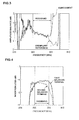
- Fig. 3 illustrates a comparison of the amplitude balance of balanced signals in the boundary acoustic wave device according to the above embodiment and an amplitude balance of balanced signals in an exemplary reference boundary acoustic wave filter device, which was prepared for comparison.
- the exemplary reference boundary acoustic wave filter device prepared for comparison was fabricated similarly to the boundary acoustic wave filter device according to the present embodiment, except that in the exemplary reference boundary acoustic wave filter device, the propagation direction of a boundary acoustic wave in the first longitudinally coupled resonator type boundary acoustic wave filter 110 was set to be the same as the propagation direction of a boundary acoustic wave in the second longitudinally coupled resonator type boundary acoustic wave filter 120.
- the balanced terminals include the first and second balanced terminals 104a and 104b.
- the amplitude balance of balanced signals refers to the intensity ratio between the amplitude of a signal output from one of the pair of balanced terminals and the amplitude of a signal output from the other one of the pair of balanced terminals.
- the ratio of the signal powers is expressed in dB.
- the amplitude balance of balanced signals is 0 (dB).
- the amplitude balance is effectively enhanced in the pass band, particularly at around 890 MHz to 894 MHz, which is the high side of the pass band.
- Fig. 4 illustrates the transmission characteristic of the balanced terminal 104a and the transmission characteristic of the balanced terminal 104b in the above exemplary reference boundary acoustic wave filter device.
- Fig. 5 illustrates the transmission characteristic of the balanced terminal 104a and the transmission characteristic of the balanced terminal 104b in the boundary acoustic wave filter device of the above embodiment.
- the solid line indicates the transmission characteristic obtained from the first balanced terminal
- the broken line indicates the transmission characteristic obtained from the second balanced terminal.
- the amplitude balance of signals output to the first and second balanced terminals illustrated in Fig. 4 is indicated by the broken line in Fig. 3
- the amplitude balance of signals output to the first and second balanced terminals illustrated in Fig. 5 is indicated by the solid line in Fig. 3 .
- a ratio of transmitted signal power to input signal power is expressed as an insertion loss (dB).
- the insertion loss of a signal output from one of the balanced terminals and the insertion loss of a signal output from the other one of the balanced terminals are significantly different, indicating that the amplitude balance of the balanced signals is degraded.
- a pass band herein refers to a pass band that is required for a boundary acoustic wave filter device.
- the boundary acoustic wave filters 110 and 120 have approximately the same design parameters.
- the insertion losses at frequencies higher than the center frequency are better than the insertion losses at frequencies lower than the center frequency.
- the insertion losses at frequencies higher than the center frequency are worse than the insertion losses at frequencies lower than the center frequency. This causes a difference in insertion loss in the pass band between the balanced signal output from the balanced terminal 104a and the balanced signal output from the balanced terminal 104b, and thus the amplitude balance is degraded.
- the electromechanical coefficient K 2 of a boundary acoustic wave in the first boundary acoustic wave filter 110 is set to be smaller than the electromechanical coefficient of a boundary acoustic wave in the second boundary acoustic wave filter 120.
- the band width of the transmission characteristic of a longitudinally coupled resonator type boundary acoustic wave filter such as the boundary acoustic wave filters 110 and 120 is approximately proportional to the electromechanical coefficient K 2 . Therefore, by setting the band width of the transmission characteristic of the first boundary acoustic wave filter 110 to be relatively small according to the above configuration, the difference in insertion loss in the pass band between the first and second boundary acoustic wave filters 110 and 120 is reduced. As a result, the amplitude balance is improved.
- the propagation directions of boundary acoustic waves in the first and second longitudinally coupled resonator type boundary acoustic wave filters are set to be different from each other, and the band widths of the filter transmission characteristics are set so that the difference between the insertion losses of the filters in the pass band is small.
- the amplitude balance is effectively improved.
- the difference in insertion loss between the first balanced terminal side and the second balanced terminal side is set to approximately 0.5 dB, and the balance is also set to approximately 0.5 dB.
- the difference in insertion loss exceeds 1 dB
- the balance exceeds 1 dB around a high frequency in the pass band.
- the propagation directions of boundary acoustic waves in the first and second boundary acoustic wave filters are set to be different from each other, preferably such that the difference between the insertion loss of a filter waveform output from the first balanced terminal in the pass band and the insertion loss of a filter waveform output from the second balanced terminal in the pass band is equal to or less than ⁇ 1 dB.
- the pass band characteristics of the first and second longitudinally coupled resonator type boundary acoustic wave filters vary depending on various factors of design parameters. As an embodiment different from the present embodiment, it can also be configured such that the propagation directions of boundary acoustic waves in the filters is set to be different from each other, such that the band widths of the transmission characteristics of the filters are generally equal, when the band widths of the transmission characteristics of the filters are different despite that the difference in insertion loss is originally small. In this case, it is preferable that the center frequencies of the filters are also set to be equal so that the transmission characteristics of the filters are approximately the same. With this arrangement, an improved amplitude balance can be obtained even in the outside of the pass band.
- the band width of a transmission characteristic herein refers to a band width corresponding to an insertion loss decreased by 3 dB from the smallest insertion loss.
- the generally equal band widths of transmission characteristics do not only mean the completely equal band widths, but also means that an allowance may be approximately ⁇ 0.2% in band width ratio expressed by the ratio of the band width of the transmission characteristic to the center frequency. That is, the generally equal band widths of the transmission characteristics include the equal band widths and band widths whose difference is approximately ⁇ 0.2% in band width ratio.
- Fig. 6 is a schematic plan view illustrating an electrode structure of a boundary acoustic wave filter device according to the second embodiment of the present invention.
- a boundary acoustic wave filter device 200 of the second embodiment is similarly configured, except that the IDT 114A provided at the center of the first longitudinally coupled resonator type boundary acoustic filter 110 is different from the IDT 114 in the first embodiment.
- like parts are designated by like reference numerals, and the description thereof will be omitted.
- series weighting is applied to the IDT 114A at the center of the longitudinally coupled resonator type boundary acoustic wave filter 110, as illustrated in the figure.
- Series weighting refers to an arrangement in which floating electrode fingers 201a and 201b are provided at the ends of the outermost electrode fingers of the IDT 114A in the boundary acoustic wave propagation direction, and the floating electrode fingers 201a and 201b are formed so as to extend to the ends of electrode fingers immediately adjacent to the outermost electrode fingers via gaps. This series weighting reduces the reception intensity of excitation of a boundary acoustic wave in a boundary between IDTs.
- Such a known technique of adjusting the pass band width by series weighting in a boundary acoustic wave filter device may be applied to the present invention to more effectively improve the balance of signals.
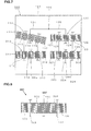
- Fig. 7 is a schematic plan view of a boundary acoustic wave filter device according to a third embodiment of the present invention.
- a boundary acoustic wave filter device 300 does not have one-terminal-pair boundary acoustic wave resonators 150, 160, and 170.
- third and fourth longitudinally coupled resonator type boundary acoustic wave filters 310 and 320 are connected to the downstream sides of the first and second longitudinally coupled resonator type boundary acoustic wave filters 110 and 120, respectively so as to form a two-stage cascade configuration. Except this two-stage cascade configuration, the third embodiment is similar to the first embodiment. Thus, like parts are designated by like reference numerals, and the description thereof will be omitted.
- the third and fourth longitudinally coupled resonator type boundary acoustic wave filters 310 and 320 have IDTs 313 to 315 and IDTs 323 to 325, respectively, and reflectors 311 and 312, and 321 and 322, respectively.
- the third and the fourth longitudinally coupled resonator type boundary acoustic wave filters 310 and 320 are configured similarly to the second longitudinally coupled resonator type boundary acoustic wave filter 120.
- the boundary acoustic wave filter device may have a configuration in which another longitudinally coupled resonator type boundary acoustic wave filter is connected in addition to at least two boundary acoustic wave filters 110 and 120.
- a 3IDT-type longitudinally coupled resonator type boundary acoustic wave filter having three IDTs is employed.
- a longitudinally coupled resonator type boundary acoustic wave filter having more IDTs such as a 5IDT type and a 7IDT type.
- first and second longitudinally coupled resonator type surface acoustic wave filters may be a boundary acoustic wave filter
- at least one of first and second longitudinally coupled resonator type acoustic wave filters may be a surface acoustic wave filter.
Landscapes
- Physics & Mathematics (AREA)
- Acoustics & Sound (AREA)
- Surface Acoustic Wave Elements And Circuit Networks Thereof (AREA)
Abstract
Description
- The present invention relates to acoustic wave filter devices utilizing surface acoustic waves or boundary acoustic waves. In particular, the present invention relates to acoustic wave filter devices having first and second longitudinally coupled resonator type acoustic wave filters formed on piezoelectric substrates and also having a balanced-to-unbalanced conversion function.
- Conventionally, surface acoustic wave filters have been in widespread use as band pass filters for mobile communication apparatuses such as mobile phones and the like. Recently, boundary acoustic wave filters utilizing boundary acoustic waves instead of surface acoustic waves have drawn attention.
- Band pass filters used in the RF stages of mobile phones are required to have balanced-to-unbalanced conversion functions. By using boundary acoustic wave filters having balanced-to-unbalanced functions as band pass filters, baluns can be omitted, which promotes miniaturization.
-
Patent Document 1 listed below discloses a surface acoustic wave filter having a balanced-to-unbalanced conversion function. -
Fig. 8 is a plan view illustrating an electrode structure of a surface acoustic wave filter described inPatent Document 1. A surfaceacoustic wave filter 501 has a configuration in which the shown electrode structure is formed on a piezoelectric substrate. InFig. 8 , first tothird IDTs 502 to 504 are arranged along a surface acoustic wave propagation direction.Reflectors - One end of the IDT 503 provided at the center is connected to an
unbalanced terminal 507 and one ends of the IDTs 502 and 504 provided at opposite sides of the IDT 503 are electrically connected to first and secondbalanced terminals - In the surface
acoustic wave filter 501, the IDTs 502 and 504 are configured such that a signal supplied from theunbalanced terminal 507 to thebalanced terminal 508 and a signal supplied from theunbalanced terminal 507 to thebalanced terminal 509 have opposite phases. The IDT 502 is cross-width weighted so that the balance is improved.
Patent Document 1:Japanese Unexamined Patent Application Publication No. 2002-374147 - Conventionally, in a surface acoustic filter having a balanced-to-unbalanced conversion function, there is a strong requirement to improve the balance between balanced signals input/output from first and second balanced terminals. In the surface
acoustic wave filter 501 described inPatent Document 1, as described above, cross-width weighting is applied to the IDT 502 connected to thebalanced terminal 508 with a view to improving the balance. Specifically, weighting is applied to at least one IDT 502, so that reception states of surface acoustic wave excitation in signals output from the IDTs 502 and IDT 504 are matched. - However, it is difficult to match the amount of surface acoustic wave excitation received at the IDT 502 side and the amount of surface acoustic wave excitation received at the IDT 504 side, making it difficult to sufficiently and precisely enhance the balance.
- In addition, it is also difficult to design weighting that allows the amounts of surface acoustic wave excitation received at the IDTs 502 and 504 to be matched.
- An object of the present invention is to overcome the disadvantage of the related art described above by providing a boundary acoustic wave filter that can improve the signal balance between a pair of balanced terminals.
- According to the present invention, there is provided an acoustic wave filter device including a piezoelectric substrate, a first longitudinally coupled resonator type acoustic wave filter which is formed on the piezoelectric substrate and has a plurality of IDT electrodes and first and second terminals, and a second longitudinally coupled resonator type acoustic wave filter which is formed on the piezoelectric substrate and has a plurality of IDT electrodes and third and fourth terminals, and having a balanced-to-unbalanced conversion function in which when identical signals are input to the first terminal and the third terminal, a phase difference between a signal output from the second terminal and a signal output from the fourth terminal is generally 180 degrees in at least a pass band, in which the first and third terminals are commonly connected and connected to an unbalanced terminal, and in which the second and fourth terminals are set as first and second balanced terminals, respectively. In the acoustic wave filter device, a propagation direction of an acoustic wave in the first longitudinally coupled resonator type acoustic wave filter and a propagation direction of an acoustic wave in the second longitudinally coupled resonator type acoustic wave filter are different from each other.
- In a specific aspect of an acoustic wave filter device according to the present invention, the propagation direction of an acoustic wave in the first longitudinally coupled resonator type acoustic wave filter and the propagation direction of an acoustic wave in the second longitudinally coupled resonator type acoustic wave filter are set to be different from each other, such that the difference between an insertion loss of a filter waveform output from the first balanced terminal in a pass band and an insertion loss of a filter waveform output from the second balanced terminal in a pass band is equal to or less than ±1 dB.
- In yet another specific aspect of an acoustic wave filter device according to the present invention, an electromechanical coefficient of one longitudinally coupled resonator type acoustic wave filter, among the first and second longitudinally coupled resonator type acoustic wave filters, in which excitation of an acoustic wave received in a space between a plurality of IDTs is stronger, is set to be smaller than an electromechanical coefficient of the other longitudinally coupled resonator type acoustic wave filter
- In yet another specific aspect of an acoustic wave filter device according to the present invention, at least one of the first and second longitudinally coupled resonator type acoustic wave filters is a surface acoustic filter.
- In yet another specific aspect of an acoustic wave filter device according to the present invention, at least one of the first and second longitudinally coupled resonator type acoustic wave filters is a boundary acoustic filter.
- In yet another specific aspect of an acoustic wave filter device according to the present invention, the piezoelectric substrate is composed of LiNbO3 and is formed so as to cover the IDTs. Euler angles φ and θ of the LiNbO3 substrate are in the ranges -31 degrees ≤ φ ≤ 31 degrees, and 90 degrees ≤ θ ≤ 130 degrees, and in the first and second longitudinally coupled resonator type acoustic wave filters, an Euler angle ψ is in the range 0 degrees ≤ ψ ≤ 60 degrees.
- In an acoustic wave filter device according to the present invention, each of the IDTs is composed of a metal selected from the group consisting of Al, Ti, Pt, Fe, Ni, Cr, Cu, Ag, W, Ta, and Au, or an alloy composed primarily of the metal.
- In another aspect of an acoustic wave filter device according to present invention, the dielectric film is composed of one type of dielectric selected from a group consisting of SiO2, SiN, quartz crystal, LBO, langasite, langanite, and glass.
- According to an acoustic wave filter device according to the present invention, in an acoustic wave filter device having a balanced-to-unbalanced conversion function, in which individual ends of first and second longitudinally coupled resonator type acoustic wave filters are connected to an unbalanced terminal and individual other ends are connected to first and second balanced terminals, a propagation direction of an acoustic wave in the first longitudinally coupled resonator type acoustic wave filter and a propagation direction of an acoustic wave in the second longitudinally coupled resonator type acoustic wave filter are different from each other. Therefore, the signal balance between the first and second balanced terminals can be effectively improved. This is for the following reasons.
- In order to set signals in the first longitudinally coupled resonator type acoustic wave filter and the second longitudinally coupled resonator type acoustic wave filter to have opposite phases, the polarity of a part of IDTs is set to be opposite. Consequently, the reception intensity of excitation of an acoustic wave in a boundary portion between IDTs in the first longitudinally coupled resonator-type acoustic wave filter has to be different from the reception intensity of excitation of an acoustic wave in a boundary portion between IDTs in the corresponding second longitudinally coupled resonator type acoustic wave filter. When the first and second longitudinally coupled resonator type acoustic wave filters have exactly the same design parameters except the above configuration, the pass band width is large in the one that has greater reception intensity of excitation of an acoustic wave in a boundary portion between IDTs. Thus, it can be considered that the signal balance between the balanced terminals is degraded.
- On the other hand, in the present invention, the acoustic wave propagation direction in the first longitudinally coupled resonator type acoustic wave filter and the acoustic wave propagation direction in the second longitudinally coupled resonator type acoustic wave filter are different from each other, and electromechanical coefficients of both the filters are different from each other. When an electromechanical coefficient decreases, the pass band width of a longitudinally coupled resonator type acoustic wave filter decreases, and when the electromechanical coefficient increases, the pass band width increases.
- In the present invention, the acoustic wave propagation directions in the first and second longitudinally coupled resonator type acoustic wave filters are set to be different from each other, such that the electromechanical coefficient of one filter, among the first longitudinally coupled resonator type acoustic wave filter and the second longitudinally coupled resonator type acoustic wave filter, in which excitation of a second acoustic wave received in the boundary portion between IDTs described above is relatively strong, is smaller than the other That is, by setting acoustic wave propagation directions in the first and second longitudinally coupled resonator type acoustic wave filters to be different from each other, the electromechanical coefficients can be individually optimized, and by setting the electromechanical coefficient of the one in which received excitation of an acoustic wave is stronger to be smaller than the other, the pass band widths of the first and second longitudinally coupled resonator type acoustic wave filters can be matched. Accordingly, the transmission characteristics of the first and second acoustic wave filters are made similar to each other, and thus the balance of balanced signals can be effectively improved.
- In other words, the acoustic wave propagation directions are set to be different from each other, such that the electromechanical coefficient of one filter, among the first and second longitudinally coupled resonator type acoustic wave filters, in which excitation of a second acoustic wave received in a boundary portion between IDTs described above is stronger, that is, the filter having a wider pass band width than the other, is smaller than the electromechanical coefficient of the other longitudinally coupled resonator type acoustic wave filter. This allows the pass band widths of both the filters to be matched, and thus the balance is improved.
- Thus, according to the present invention, it is only necessary to set the acoustic wave propagation directions in the first and second longitudinally coupled resonator type acoustic wave filters to be different from each other. Thus, the balance can be readily and effectively improved without complicated design operations.
- When the propagation directions of acoustic waves in the first and second longitudinally coupled resonator type acoustic wave filters are set to be different from each other, such that the difference between an insertion loss of a filter waveform output from the first balanced terminal in a pass band and an insertion loss of a filter waveform output from the second balanced terminal in a pass band is equal to or less than ±1 dB, cancellation of the amplitudes of opposite-phase signals is performed efficiently, permitting further improvement of the balance.
- Note that the difference between an insertion loss of a filter waveform output from the first balanced terminal in a pass band and an insertion loss of a filter waveform output from the second balanced terminal in a pass band being equal to or less than ±1 dB means that the difference between insertion losses which can be measured at the same frequency in the pass bands of both the filters are all equal to or less than ±1 dB.
- In particular, when the propagation directions of acoustic waves in the first and second longitudinally coupled resonator type acoustic wave filters are selected such that the pass band width of a filter waveform output from the first balanced terminal and the pass band width of a filter waveform output from the second balanced terminal are the same, the signal balance between the first and second balanced terminals can further be improved.
- In addition, when an electromechanical coefficient of one of the longitudinally coupled resonator type acoustic wave filters, in which excitation of an acoustic wave received in a space between IDTs is stronger than the other, is set to be smaller than the electromechanical coefficient of the other longitudinally coupled resonator type acoustic wave filter, the signal balance between the first and second balanced terminals can be enhanced.
- In the present invention, at least one of the first and second longitudinally coupled resonator type acoustic wave filters may be a surface acoustic filter. In this case, a surface acoustic wave filter device having excellent balance can be provided in accordance with the present invention.
- In addition, in the present invention, one of the first and second longitudinally coupled resonator type acoustic wave filters may utilize a boundary acoustic filter. In this case, a boundary acoustic wave filter device having excellent balance can be provided in accordance with the present invention.
- When a piezoelectric substrate is composed of LiNbO3, when a dielectric film is formed on the piezoelectric substrate including IDTs, when Euler angles φ and θ among Euler angels of the piezoelectric substrate are in the ranges -31 degrees ≤ φ ≤ 31 degrees, and 90 degrees ≤ θ ≤ 130 degrees, and when an Euler angle ψ in the first and second acoustic wave filters is in the range 0 degrees ≤ ψ ≤ 60 degrees, a electromechanical coefficient K2 can be changed in a wide range by changing the Euler angle ψ corresponding to the propagation direction in the range from 0 degrees to 60 degrees. In addition, this range permits reduction of propagation loss of a boundary acoustic wave and reduction of insertion loss.
- When an IDT is composed of a metal selected from the group consisting of Al, Ti, Pt, Fe, Ni, Cr, Cu, Ag, W, Ta, and Au, or an alloy composed primarily of the metal, it is possible to form an IDT using a typical electrode material which is generally used in surface acoustic wave devices and boundary acoustic wave devices.
- When a dielectric film is composed of one type of dielectric selected from a group consisting of SiO2, SiN, quartz crystal, LBO, langasite, langanite, and glass, a boundary acoustic wave device with excellent balance and excellent frequency temperature characteristics can be provided.
-
-
Fig. 1 is a schematic plan view illustrating an electrode structure of a boundary acoustic wave filter device according to a first embodiment of the present invention. -
Fig. 2 is a schematic partial fragmentary elevational cross-sectional view of a boundary acoustic wave device according to the first embodiment of the present invention. -
Fig. 3 is a diagram illustrating a relationship between amplitude balance and frequency in a boundary acoustic wave device of the first embodiment and an exemplary reference boundary acoustic wave filter device. -
Fig. 4 is a diagram illustrating transmission characteristics obtained from first and second balanced terminals in the exemplary reference boundary acoustic wave filter device. -
Fig. 5 is a diagram illustrating transmission characteristics obtained from first and second balanced terminals in the boundary acoustic wave filter device of the first embodiment. -
Fig. 6 is a schematic plan view illustrating an electrode structure of a boundary acoustic wave filter device according to a second embodiment of the present invention. -
Fig. 7 is a schematic plan view illustrating an electrode structure of a boundary acoustic wave filter device according to a third embodiment of the present invention. -
Fig. 8 is a schematic plan view illustrating an electrode structure of a conventional surface acoustic wave filter device. -
- 100 boundary acoustic wave filter device
- 101 LiNbO3 substrate
- 102 electrode pattern
- 103 SiO2 film
- 104 unbalanced terminal
- 104a, 104b first and second balanced terminals
- 105a, 105b connection conductive portions
- 110 longitudinally coupled resonator type boundary acoustic wave filter
- 111, 112 reflectors
- 113 to 115 IDTs
- 114A IDT
- 120 longitudinally coupled resonator type boundary acoustic filter
- 121, 122 reflectors
- 123 to 125 IDTs
- 131, 135 lines
- 133, 136 lines
- 150, 160, 170 one-terminal-pair boundary acoustic wave resonators
- 200 boundary acoustic wave filter device
- 201a, 201b floating electrode fingers
- 300 boundary acoustic wave filter device
- 310, 320 longitudinally coupled resonator type boundary acoustic wave filters
- 311, 312 reflectors
- 313 to 315 IDTs
- 320 longitudinally coupled resonator type boundary acoustic wave filter
- 321, 322 reflectors
- 323 to 325 IDTs
- In the following, the present invention will be clarified by describing detailed embodiments of the present invention with reference to the drawings.
-
Fig. 1 is a schematic plan view illustrating an electrode structure of a boundary acoustic wave device according to an embodiment of the present invention.Fig. 2 is a schematic partial fragmentary elevational cross-sectional view for describing the boundary acoustic wave device. - As illustrated in
Fig. 2 , a boundary acousticwave filter device 100 according to the present embodiment has a LiNbO3 substrate 101 as a piezoelectric substrate, which is composed of LiNbO3 single crystal. A SiO2 film 103 is disposed on the LiNbO3 substrate 101 as a dielectric film. The boundary acousticwave filter device 100 of the present embodiment utilizes an SH boundary acoustic wave propagating along the interface between the LiNbO3 substrate 101 and the SiO2 film 103. - In
Fig. 2 , an electrode pattern 102 for receiving excitation of the boundary acoustic wave described above is schematically illustrated. This electrode pattern 102 specifically corresponds to the electrode structure illustrated by the schematic plan view inFig. 1 . - Dielectric film cavity portions 103a and 103b are formed in the SiO2 film 103. In each of the dielectric film cavity portions 103a and 103b, a part of the electrode pattern 102 is exposed. Connection conductive portion 105a and 105b are formed on the dielectric film 103. The connection conductive portions 105a and 105b extend inside the dielectric film cavity portions 103a and 103b and are electrically connected to parts of the electrode pattern 102.
- First and second balanced terminals 104a and 104b are formed on the upper surface of the dielectric film 103. The balanced terminals 104a and 104b are electrically connected to the connection conductive portions 105a and 105b, respectively.
- The connection conductive portions 105a and 105b may be formed of an appropriate metal such as Al and Cu or an alloy. Similarly, the first and second balanced terminals 104a and 104b may be formed of an appropriate metal such as Al and Cu or an alloy.
- As illustrated in
Fig. 2 , the electrode pattern 102 formed on the LiNbO3 substrate 101 is composed of a gold thin film having a thickness of 0.05 λ. Note that λ represents a wavelength corresponding to the center frequency of a boundary acoustic wave in the pass band of the boundary acousticwave filter device 100. - Euler angles φ and θ of the LiNbO3 substrate 101 are set to 0 degrees and 105 degrees, respectively. In
Fig. 1 , the number of electrode fingers of an IDT and the number of gratings of a reflector, which will be described below, are schematically illustrated as being smaller than the actual numbers. - For the Euler angles (φ, e, ψ), known right-handed Euler angles are employed. Specifically, for crystal axes X, Y, Z of LiNbO3 single crystal, the X-axis is rotated counterclockwise around the Z-axis by φ so that the Xa-axis is obtained. Then, the Z-axis is rotated counterclockwise around the Xa-axis by θ so that Z'-axis is obtained. A plane that includes the Xa-axis and for which the Z'-axis is normal thereto is set as the cut surface of the substrate. The direction obtained by rotating the Xa-axis counterclockwise around the Z'-axis by ψ is set as the propagation direction of a boundary acoustic wave.
- For crystal axes X, Y, and Z of the LiNbO3 single crystal which are given as the initial values of the Euler angles, the Z-axis is parallel to the c-axis, the X-axis is parallel to any one of a-axes that extend in three equivalent directions, and the Y-axis extends in a direction of the normal line of the plane including the X-axis and the Z-axis.
- In
Fig. 1 , the direction of the normal line with respect to the plane of the drawing is obtained by rotating the crystal Z-axis of the LiNbO3 substrate 101 counterclockwise around the crystal X-axis by 105 degrees. In addition, inFig. 1 , the right-left direction in the drawing is the direction of the crystal X-axis of the LiNbO3 crystal substrate 101. Thus, inFig. 1 , the Euler angle corresponding to propagation in the right-left direction in the figure is ψ = 0 degrees. The Euler angle of a boundary acoustic wave propagating in the top-bottom direction in the figure is ψ = 90 degrees. - The
electrode pattern 2 described above has a first longitudinally coupled resonator type boundaryacoustic wave filter 110, a second longitudinally coupled resonator type boundaryacoustic wave filter 120, one-terminal-pair boundaryacoustic wave resonators - The first longitudinally coupled resonator type boundary
acoustic wave filter 110 hasIDTs 113 to 115 arranged along the boundary acoustic wave propagation direction, andreflectors IDT 113 to 115 are provided in the boundary acoustic wave propagation direction. Similarly, the second longitudinally coupled resonator type boundaryacoustic wave filter 120 hasIDTs 123 to 125 arranged along the boundary acoustic wave propagation direction andreflectors - The first longitudinally coupled resonator type boundary
acoustic wave filter 110 and the second longitudinally coupled resonator type boundaryacoustic wave filter 120 have approximately the same design parameters. That is, the first longitudinally coupled resonator type boundaryacoustic wave filter 110 and the second longitudinally coupled resonator type boundaryacoustic wave filter 120 are designed to have generally the same frequency characteristics. However, the polarities of theIDT 114 and theIDT 124 are set to be opposite. - On the other hand, one ends of the
IDTs lines lines unbalanced terminal 104 via the one-terminal-pair boundaryacoustic wave resonator 150. Thisunbalanced terminal 104 is formed on the upper surface of the SiO2 film 103, similarly to the first and second balanced terminals 104a and 104b illustrated inFig. 2 . Theunbalanced terminal 104 is electrically connected to the boundaryacoustic wave resonator 150 through a connection conductive portion (not shown). - On the other hand, the
IDTs acoustic wave filter 110 are connected to the first balanced terminal 104a via the one-terminal-pair boundaryacoustic wave resonator 160 through aline 133. Similarly, theIDTs acoustic wave filter 120 are connected to the second balanced terminal 104b via the one-terminal-pair boundaryacoustic wave resonator 170 through aline 136. The boundary acoustic wave propagation direction in the second longitudinally coupled resonator type boundaryacoustic wave filter 120 and the one-terminal-pair boundaryacoustic wave resonators acoustic wave filter 110 is set to 10 degrees. - That is, the first and second longitudinally coupled resonator type boundary acoustic wave filters 110 and 120 are configured to have generally the same frequency characteristics. However, the boundary acoustic wave propagation directions in the first and second longitudinally coupled resonator type boundary acoustic wave filters 110 and 120 are set to be different from each other.
- The boundary acoustic
wave filter device 100 according to the present embodiment has theunbalanced terminal 104 and the first and second balanced terminals 104a and 104b, as described above. The polarity of theIDT 114 and the polarity of theIDT 124 are set to be opposite so that the difference in phase between a signal supplied from theunbalanced terminal 104 to the first balanced terminal 104a and a signal supplied from theunbalanced terminal 104 to the second balanced terminal 104b is generally 180 degrees. Therefore, the boundary acousticwave filter device 100 has a balanced-to-unbalanced function. - Each of the longitudinally coupled resonator type boundary acoustic wave filters 110 and 120 has filter characteristics in which signals within the pass band are passed and signals in the attenuation band are attenuated. In addition, each of the one-terminal-pair boundary
acoustic wave resonators wave filter device 100 and to have a high impedance in a band outside the pass band. Thus, the amount of attenuation outside the pass band is increased by connecting the one-terminal-pair boundaryacoustic wave resonators 150 to 170. - In addition, in the boundary acoustic
wave filter device 100, since the propagation directions of boundary acoustic waves in the first and second longitudinally coupled resonator type boundary acoustic wave filters 110 and 120 are set to be different from each other, the balance can be effectively improved. This will be described in more detail with reference toFig. 3 to Fig. 5 . -
Fig. 3 illustrates a comparison of the amplitude balance of balanced signals in the boundary acoustic wave device according to the above embodiment and an amplitude balance of balanced signals in an exemplary reference boundary acoustic wave filter device, which was prepared for comparison. The exemplary reference boundary acoustic wave filter device prepared for comparison was fabricated similarly to the boundary acoustic wave filter device according to the present embodiment, except that in the exemplary reference boundary acoustic wave filter device, the propagation direction of a boundary acoustic wave in the first longitudinally coupled resonator type boundaryacoustic wave filter 110 was set to be the same as the propagation direction of a boundary acoustic wave in the second longitudinally coupled resonator type boundaryacoustic wave filter 120. - In
Fig. 3 , the solid line indicates the result in the case of the embodiment, and the broken line indicates the result in the case of the exemplary reference. The balanced terminals include the first and second balanced terminals 104a and 104b. The amplitude balance of balanced signals refers to the intensity ratio between the amplitude of a signal output from one of the pair of balanced terminals and the amplitude of a signal output from the other one of the pair of balanced terminals. The ratio of the signal powers is expressed in dB. Ideally, the amplitude balance of balanced signals is 0 (dB). - As is apparent from
Fig. 3 , in the case of the present embodiment, as compared to the case of the reference, the amplitude balance is effectively enhanced in the pass band, particularly at around 890 MHz to 894 MHz, which is the high side of the pass band. -
Fig. 4 illustrates the transmission characteristic of the balanced terminal 104a and the transmission characteristic of the balanced terminal 104b in the above exemplary reference boundary acoustic wave filter device.Fig. 5 illustrates the transmission characteristic of the balanced terminal 104a and the transmission characteristic of the balanced terminal 104b in the boundary acoustic wave filter device of the above embodiment. - In each of
Fig. 4 andFig. 5 , the solid line indicates the transmission characteristic obtained from the first balanced terminal, and the broken line indicates the transmission characteristic obtained from the second balanced terminal. - The amplitude balance of signals output to the first and second balanced terminals illustrated in
Fig. 4 is indicated by the broken line inFig. 3 , and the amplitude balance of signals output to the first and second balanced terminals illustrated inFig. 5 is indicated by the solid line inFig. 3 . - In
Fig. 4 andFig. 5 , for the transmission characteristic, a ratio of transmitted signal power to input signal power is expressed as an insertion loss (dB). - As can be seen from
Fig. 4 , in the case of the exemplary reference, the insertion loss of a signal output from one of the balanced terminals and the insertion loss of a signal output from the other one of the balanced terminals are significantly different, indicating that the amplitude balance of the balanced signals is degraded. - Note that a pass band herein refers to a pass band that is required for a boundary acoustic wave filter device.
- On the other hand, as is apparent from
Fig. 5 , according to the present embodiment, in the transmission characteristics obtained from the first and second balanced terminals 104a and 104b, the difference between the attenuation losses in the pass band is small, indicating that the amplitude balance of the balanced signals is improved. - This may be for the following reasons.
- That is, in the exemplary reference boundary acoustic wave filter device, the boundary acoustic wave propagation directions in the first and second longitudinally coupled resonator type boundary acoustic wave filters are the same and both are set as ψ = 0 degree. In addition, the boundary acoustic wave filters 110 and 120 have approximately the same design parameters. In this case, in the transmission characteristic of the boundary
acoustic wave filter 110, in which boundary acoustic wave excitation is received in a space between IDTs, the insertion losses at frequencies higher than the center frequency are better than the insertion losses at frequencies lower than the center frequency. On the other hand, in the transmission characteristic of the boundaryacoustic wave filter 120, in which boundary acoustic wave excitation is not received in a space between IDTs, the insertion losses at frequencies higher than the center frequency are worse than the insertion losses at frequencies lower than the center frequency. This causes a difference in insertion loss in the pass band between the balanced signal output from the balanced terminal 104a and the balanced signal output from the balanced terminal 104b, and thus the amplitude balance is degraded. - On the other hand, in the case of the above embodiment, the boundary acoustic wave propagation direction in the first longitudinally coupled resonator type boundary
acoustic wave filter 110 is set as ψ = 10 degrees. The boundary acoustic wave propagation direction in the second longitudinally coupled resonator type boundaryacoustic wave filter 120 is set as ψ = 0 degrees. Thus, the electromechanical coefficient K2 of a boundary acoustic wave in the first boundaryacoustic wave filter 110 is set to be smaller than the electromechanical coefficient of a boundary acoustic wave in the second boundaryacoustic wave filter 120. The band width of the transmission characteristic of a longitudinally coupled resonator type boundary acoustic wave filter such as the boundary acoustic wave filters 110 and 120 is approximately proportional to the electromechanical coefficient K2. Therefore, by setting the band width of the transmission characteristic of the first boundaryacoustic wave filter 110 to be relatively small according to the above configuration, the difference in insertion loss in the pass band between the first and second boundary acoustic wave filters 110 and 120 is reduced. As a result, the amplitude balance is improved. - Thus, according to the present embodiment, the propagation directions of boundary acoustic waves in the first and second longitudinally coupled resonator type boundary acoustic wave filters are set to be different from each other, and the band widths of the filter transmission characteristics are set so that the difference between the insertion losses of the filters in the pass band is small. Thus, the amplitude balance is effectively improved.
- As is apparent from
Fig. 5 , in the boundary acoustic wave device of the present embodiment, the difference in insertion loss between the first balanced terminal side and the second balanced terminal side is set to approximately 0.5 dB, and the balance is also set to approximately 0.5 dB. On the other hand, as is apparent fromFig. 4 illustrating the result of the case of the exemplary reference, in the case of the exemplary reference, the difference in insertion loss exceeds 1 dB, and the balance exceeds 1 dB around a high frequency in the pass band. Specifically, in the present invention, it is desirable that the propagation directions of boundary acoustic waves in the first and second boundary acoustic wave filters are set to be different from each other, preferably such that the difference between the insertion loss of a filter waveform output from the first balanced terminal in the pass band and the insertion loss of a filter waveform output from the second balanced terminal in the pass band is equal to or less than ±1 dB. - Obviously, the pass band characteristics of the first and second longitudinally coupled resonator type boundary acoustic wave filters vary depending on various factors of design parameters. As an embodiment different from the present embodiment, it can also be configured such that the propagation directions of boundary acoustic waves in the filters is set to be different from each other, such that the band widths of the transmission characteristics of the filters are generally equal, when the band widths of the transmission characteristics of the filters are different despite that the difference in insertion loss is originally small. In this case, it is preferable that the center frequencies of the filters are also set to be equal so that the transmission characteristics of the filters are approximately the same. With this arrangement, an improved amplitude balance can be obtained even in the outside of the pass band.
- The band width of a transmission characteristic herein refers to a band width corresponding to an insertion loss decreased by 3 dB from the smallest insertion loss.
- The generally equal band widths of transmission characteristics do not only mean the completely equal band widths, but also means that an allowance may be approximately ±0.2% in band width ratio expressed by the ratio of the band width of the transmission characteristic to the center frequency. That is, the generally equal band widths of the transmission characteristics include the equal band widths and band widths whose difference is approximately ±0.2% in band width ratio.
- When a LiNbO3 substrate is used, when Euler angles φ and θ are in the ranges of -31 degrees ≤ φ ≤ +31 degrees and 90 degrees ≤ θ ≤ 130 degrees, the Euler angle ψ, which represents a propagation direction of a boundary acoustic wave propagating along the boundary to a laminated dielectric film, is changed in a range of 0 degree to 60 degrees. This allows the electromechanical coefficient K2 to be changed in a range of 16% to approximately 0%. In addition, in this range, no propagation loss of a boundary acoustic wave occurs. Therefore, by setting the values of φ and θ of the LiNbO3 substrate within the above ranges, a boundary acoustic wave filter device with low loss can be provided.
-
Fig. 6 is a schematic plan view illustrating an electrode structure of a boundary acoustic wave filter device according to the second embodiment of the present invention. A boundary acousticwave filter device 200 of the second embodiment is similarly configured, except that the IDT 114A provided at the center of the first longitudinally coupled resonator type boundaryacoustic filter 110 is different from theIDT 114 in the first embodiment. Thus, like parts are designated by like reference numerals, and the description thereof will be omitted. - In the boundary acoustic
wave filter device 200 according to the present embodiment, series weighting is applied to the IDT 114A at the center of the longitudinally coupled resonator type boundaryacoustic wave filter 110, as illustrated in the figure. Series weighting refers to an arrangement in which floating electrode fingers 201a and 201b are provided at the ends of the outermost electrode fingers of the IDT 114A in the boundary acoustic wave propagation direction, and the floating electrode fingers 201a and 201b are formed so as to extend to the ends of electrode fingers immediately adjacent to the outermost electrode fingers via gaps. This series weighting reduces the reception intensity of excitation of a boundary acoustic wave in a boundary between IDTs. This makes it possible to narrow the bandwidth of the first longitudinally coupled resonator type boundaryacoustic wave filter 110, which has a large pass band width, when it is designed to have the same frequency characteristics. It has been known that series weighting applied to an IDT permits adjustment of the pass band width of a longitudinally coupled resonator type boundary acoustic wave filter - Such a known technique of adjusting the pass band width by series weighting in a boundary acoustic wave filter device may be applied to the present invention to more effectively improve the balance of signals.
- In the second embodiment, the Euler angle ψ corresponding to a boundary acoustic wave propagation direction in the first longitudinally coupled resonator type boundary
acoustic wave filter 110 can be set to be smaller than the Euler angle ψ corresponding to a boundary acoustic wave propagation direction in the first longitudinally coupled resonator type boundary acoustic wave filter of the longitudinally coupled resonator type boundary acoustic wave filters of the first embodiment, and it is set as ψ = 5 degrees. This is because the band width can be adjusted by the series weighting described above and thus only a small amount of adjustment of a pass band width for the boundary acoustic wave propagation direction is necessary. -
Fig. 7 is a schematic plan view of a boundary acoustic wave filter device according to a third embodiment of the present invention. - A boundary acoustic
wave filter device 300 according to the third embodiment does not have one-terminal-pair boundaryacoustic wave resonators - The third and fourth longitudinally coupled resonator type boundary acoustic wave filters 310 and 320 have
IDTs 313 to 315 andIDTs 323 to 325, respectively, andreflectors acoustic wave filter 120. - Thus, the boundary acoustic wave filter device according the present invention may have a configuration in which another longitudinally coupled resonator type boundary acoustic wave filter is connected in addition to at least two boundary acoustic wave filters 110 and 120.
- In the first to third embodiments described above, a 3IDT-type longitudinally coupled resonator type boundary acoustic wave filter having three IDTs is employed. However, it is also possible to use a longitudinally coupled resonator type boundary acoustic wave filter having more IDTs such as a 5IDT type and a 7IDT type.
- In addition, while a boundary acoustic wave filter device has been described in the first to third embodiments, the present invention may be applied to a surface acoustic wave device utilizing surface acoustic waves. Specifically, at least one of first and second longitudinally coupled resonator type surface acoustic wave filters may be a boundary acoustic wave filter, and at least one of first and second longitudinally coupled resonator type acoustic wave filters may be a surface acoustic wave filter.
Claims (8)
- An acoustic wave filter device comprising:a piezoelectric substrate;a first longitudinally coupled resonator type acoustic wave filter which is formed on the piezoelectric substrate and has a plurality of IDT electrodes and first and second terminals; anda second longitudinally coupled resonator type acoustic wave filter which is formed on the piezoelectric substrate and has a plurality of IDT electrodes and third and fourth terminals,the acoustic wave filter device having a balanced-to-unbalanced conversion function in whichwhen identical signals are input to the first terminal and the third terminal, a phase difference between a signal output from the second terminal and a signal output from the fourth terminal is approximately 180 degrees in at least a pass band,the first and third terminals are commonly connected and connected to an unbalanced terminal, andthe second and fourth terminals are set as first and second balanced terminals, respectively,wherein a propagation direction of an acoustic wave in the first longitudinally coupled resonator type acoustic wave filter and a propagation direction of an acoustic wave in the second longitudinally coupled resonator type acoustic wave filter are different from each other.
- The acoustic wave filter device according to claim 1, wherein the propagation direction of an acoustic wave in the first longitudinally coupled resonator type acoustic wave filter and the propagation direction of an acoustic wave in the second longitudinally coupled resonator type acoustic wave filter are set to be different from each other, such that the difference between an insertion loss of a filter waveform output from the first balanced terminal in a pass band and an insertion loss of a filter waveform output from the second balanced terminal in a pass band is equal to or less than ±1 dB.
- The acoustic wave filter device according to claim 1 or 2, wherein an electromechanical coefficient of one longitudinally coupled resonator type acoustic wave filter, among the first and second longitudinally coupled resonator type acoustic wave filters, in which excitation of an acoustic wave received in a space between a plurality of IDTs is stronger, is set to be smaller than an electromechanical coefficient of the other longitudinally coupled resonator type acoustic wave filter.
- The acoustic wave filter device according to any one of claims 1 to 3, wherein at least one of the first and second longitudinally coupled resonator type acoustic wave filters is a surface acoustic filter.
- The acoustic wave filter device according to any one of claims 1 to 3, wherein at least one of the first and second longitudinally coupled resonator type acoustic wave filters is a boundary acoustic filter.
- The acoustic wave filter device according to claim 5,
wherein
the piezoelectric substrate is composed of LiNbO3,
the dielectric film is formed so as to cover the IDTs on the piezoelectric substrate,
Euler angles φ and θ of the LiNbO3 substrate are in the ranges -31 degrees ≤ φ ≤ 31 degrees, and 90 degrees ≤ θ ≤ 130 degrees, and
in the first and second longitudinally coupled resonator type acoustic wave filters, an Euler angle ψ is in the range 0 degrees ≤ ψ ≤ 60 degrees. - The acoustic wave filter device according to any one of claims 1 to 6, wherein each of the IDTs is composed of a metal selected from the group consisting of Al, Ti, Pt, Fe, Ni, Cr, Cu, Ag, W, Ta, and Au, or an alloy composed primarily of the metal.
- The acoustic wave filter device according to claim 6, wherein the dielectric film is composed of one type of dielectric selected from the group consisting of SiO2, SiN, quartz crystal, LBO, langasite, langanite, and glass.
Applications Claiming Priority (2)
| Application Number | Priority Date | Filing Date | Title |
|---|---|---|---|
| JP2005204758 | 2005-07-13 | ||
| PCT/JP2006/310268 WO2007007475A1 (en) | 2005-07-13 | 2006-05-23 | Elastic wave filter |
Publications (2)
| Publication Number | Publication Date |
|---|---|
| EP1903676A1 true EP1903676A1 (en) | 2008-03-26 |
| EP1903676A4 EP1903676A4 (en) | 2012-08-22 |
Family
ID=37636875
Family Applications (1)
| Application Number | Title | Priority Date | Filing Date |
|---|---|---|---|
| EP06746752A Withdrawn EP1903676A4 (en) | 2005-07-13 | 2006-05-23 | Elastic wave filter |
Country Status (6)
| Country | Link |
|---|---|
| US (1) | US7804384B2 (en) |
| EP (1) | EP1903676A4 (en) |
| JP (1) | JPWO2007007475A1 (en) |
| KR (1) | KR100898703B1 (en) |
| CN (1) | CN101218743B (en) |
| WO (1) | WO2007007475A1 (en) |
Cited By (1)
| Publication number | Priority date | Publication date | Assignee | Title |
|---|---|---|---|---|
| EP2773040A4 (en) * | 2011-10-24 | 2015-06-10 | Murata Manufacturing Co | SURFACE ACOUSTIC WAVE DEVICE |
Families Citing this family (12)
| Publication number | Priority date | Publication date | Assignee | Title |
|---|---|---|---|---|
| WO2009119007A1 (en) | 2008-03-27 | 2009-10-01 | 株式会社村田製作所 | Surface acoustic wave filter device |
| WO2009128202A1 (en) * | 2008-04-14 | 2009-10-22 | 株式会社村田製作所 | Surface acoustic wave filter device |
| JP5041063B2 (en) * | 2008-06-30 | 2012-10-03 | 株式会社村田製作所 | Band stop filter |
| JPWO2010125934A1 (en) * | 2009-04-30 | 2012-10-25 | 株式会社村田製作所 | Elastic wave device |
| JP2011066747A (en) * | 2009-09-18 | 2011-03-31 | Panasonic Corp | Surface acoustic wave filter |
| JP5327378B2 (en) | 2010-02-17 | 2013-10-30 | 株式会社村田製作所 | Elastic wave device |
| JP6368332B2 (en) * | 2016-03-04 | 2018-08-01 | 太陽誘電株式会社 | Filters and duplexers |
| JP6572842B2 (en) * | 2016-07-15 | 2019-09-11 | 株式会社村田製作所 | Multiplexer, high-frequency front-end circuit, and communication device |
| KR20180064168A (en) * | 2016-12-05 | 2018-06-14 | 삼성전기주식회사 | Acoustic wave filter device and method for manufacturing the same |
| DE102017127713B3 (en) * | 2017-11-23 | 2019-02-28 | RF360 Europe GmbH | Electroacoustic filter with reduced acoustic coupling, method for reducing the acoustic coupling and multiplexer |
| DE102018130144A1 (en) * | 2018-11-28 | 2020-05-28 | RF360 Europe GmbH | Electroacoustic resonator and RF filter |
| WO2020138290A1 (en) | 2018-12-28 | 2020-07-02 | 株式会社村田製作所 | Filter device and multiplexer |
Family Cites Families (26)
| Publication number | Priority date | Publication date | Assignee | Title |
|---|---|---|---|---|
| GB1449841A (en) * | 1973-04-09 | 1976-09-15 | Mullard Ltd | Oscillators |
| JPS53145595A (en) * | 1977-05-25 | 1978-12-18 | Nippon Telegr & Teleph Corp <Ntt> | Elastic surface wave oscillator |
| JPS58130613A (en) | 1982-01-29 | 1983-08-04 | Citizen Watch Co Ltd | Surface acoustic wave device |
| JPS59151517A (en) | 1983-02-18 | 1984-08-30 | Nec Corp | Elastic surface wave element |
| JPH05335881A (en) * | 1992-06-04 | 1993-12-17 | Murata Mfg Co Ltd | Longitudinal dual mode surface acoustic wave filter |
| JPH06268475A (en) | 1993-03-10 | 1994-09-22 | Fujitsu Ltd | Surface acoustic wave filter |
| JPH07283688A (en) | 1994-04-07 | 1995-10-27 | Matsushita Electric Ind Co Ltd | Surface acoustic wave filter |
| JPH11136081A (en) | 1997-10-27 | 1999-05-21 | Kyocera Corp | Surface acoustic wave device |
| US6278340B1 (en) * | 1999-05-11 | 2001-08-21 | Industrial Technology Research Institute | Miniaturized broadband balun transformer having broadside coupled lines |
| US6426583B1 (en) * | 1999-06-14 | 2002-07-30 | Matsushita Electric Industrial Co., Ltd. | Surface acoustic wave element, method for producing the same and surface acoustic wave device using the same |
| JP3780408B2 (en) * | 2001-01-26 | 2006-05-31 | 株式会社村田製作所 | Surface acoustic wave filter device |
| JP4109877B2 (en) * | 2001-03-04 | 2008-07-02 | 和彦 山之内 | Surface acoustic wave functional element |
| EP1239588A2 (en) | 2001-03-04 | 2002-09-11 | Kazuhiko Yamanouchi | Surface acoustic wave substrate and surface acoustic wave functional element |
| JP3509764B2 (en) | 2001-03-23 | 2004-03-22 | 株式会社村田製作所 | Surface acoustic wave device, communication device |
| JP3534080B2 (en) * | 2001-03-23 | 2004-06-07 | 株式会社村田製作所 | Surface acoustic wave filter device |
| KR100609219B1 (en) | 2001-04-09 | 2006-08-02 | 가부시키가이샤 무라타 세이사쿠쇼 | Surface acoustic wave apparatus and communication unit |
| JP3520420B2 (en) | 2001-04-09 | 2004-04-19 | 株式会社村田製作所 | Surface acoustic wave device, communication device |
| JP3873807B2 (en) * | 2001-06-22 | 2007-01-31 | 株式会社村田製作所 | Surface acoustic wave device, communication device |
| JP4182157B2 (en) * | 2002-08-12 | 2008-11-19 | 株式会社村田製作所 | Surface wave device |
| JP2004166213A (en) * | 2002-09-20 | 2004-06-10 | Murata Mfg Co Ltd | Surface acoustic wave device, and communication apparatus |
| JP2004274696A (en) | 2002-10-04 | 2004-09-30 | Seiko Epson Corp | Surface acoustic wave device and method for adjusting temperature characteristics of surface acoustic wave device |
| ATE451752T1 (en) | 2003-02-10 | 2009-12-15 | Murata Manufacturing Co | ELASTIC LIMIT SHAFT DEVICE |
| JP4100249B2 (en) * | 2003-05-19 | 2008-06-11 | 株式会社村田製作所 | Surface acoustic wave device, communication device |
| JP3894917B2 (en) * | 2003-11-12 | 2007-03-22 | 富士通メディアデバイス株式会社 | Boundary acoustic wave device and manufacturing method thereof |
| WO2005060094A1 (en) * | 2003-12-16 | 2005-06-30 | Murata Manufacturing Co., Ltd. | Acoustic boundary wave device |
| JPWO2006087875A1 (en) * | 2005-02-16 | 2008-07-03 | 株式会社村田製作所 | Balanced elastic wave filter device |
-
2006
- 2006-05-23 KR KR1020087001017A patent/KR100898703B1/en active Active
- 2006-05-23 WO PCT/JP2006/310268 patent/WO2007007475A1/en not_active Ceased
- 2006-05-23 CN CN2006800250689A patent/CN101218743B/en active Active
- 2006-05-23 JP JP2007524538A patent/JPWO2007007475A1/en active Pending
- 2006-05-23 US US11/995,208 patent/US7804384B2/en active Active
- 2006-05-23 EP EP06746752A patent/EP1903676A4/en not_active Withdrawn
Cited By (2)
| Publication number | Priority date | Publication date | Assignee | Title |
|---|---|---|---|---|
| EP2773040A4 (en) * | 2011-10-24 | 2015-06-10 | Murata Manufacturing Co | SURFACE ACOUSTIC WAVE DEVICE |
| US9276558B2 (en) | 2011-10-24 | 2016-03-01 | Murata Manufacturing Co., Ltd. | Surface acoustic wave device including a confinement layer |
Also Published As
| Publication number | Publication date |
|---|---|
| CN101218743A (en) | 2008-07-09 |
| US7804384B2 (en) | 2010-09-28 |
| KR100898703B1 (en) | 2009-05-20 |
| CN101218743B (en) | 2012-04-25 |
| KR20080028427A (en) | 2008-03-31 |
| WO2007007475A1 (en) | 2007-01-18 |
| EP1903676A4 (en) | 2012-08-22 |
| US20090224852A1 (en) | 2009-09-10 |
| JPWO2007007475A1 (en) | 2009-01-29 |
Similar Documents
| Publication | Publication Date | Title |
|---|---|---|
| US7378923B2 (en) | Balanced SAW filter | |
| WO2019117133A1 (en) | Multiplexer, high frequency front end circuit, and communication device | |
| US20160056793A1 (en) | Ladder-type surface acoustic wave filter including series and parallel resonators | |
| US7876176B2 (en) | Acoustic wave filter device and duplexer | |
| EP2068444B1 (en) | Acoustic wave filter | |
| US20020017969A1 (en) | Longitudinally coupled resonator-type surface acoustic wave filter | |
| US7532090B2 (en) | Acoustic wave filter device and duplexer | |
| US7439827B2 (en) | Surface acoustic wave filter device | |
| WO2019017422A1 (en) | Multiplexer, high-frequency front end circuit, and communication device | |
| US7804384B2 (en) | Acoustic wave filter device utilizing filters having different acoustic wave propagation directions | |
| US20090289740A1 (en) | Acoustic wave filter apparatus and duplexer | |
| EP1289135B1 (en) | Surface acoustic wave device | |
| JP2001077662A (en) | Surface wave device and communication device | |
| US7479854B2 (en) | Balanced-type surface acoustic wave filter | |
| JP2014160888A (en) | Acoustic wave resonator, acoustic wave filter using the same and antenna duplexer | |
| US8525621B2 (en) | Boundary acoustic wave filter | |
| US7746199B2 (en) | Acoustic wave device | |
| KR100840872B1 (en) | Balanced acoustic wave filter device | |
| EP1267490A2 (en) | Longitudinally-coupled resonator surface-acoustic wave filter and communications apparatus using the same | |
| US7808344B2 (en) | Boundary acoustic wave filter | |
| JPH05335881A (en) | Longitudinal dual mode surface acoustic wave filter | |
| WO2009128202A1 (en) | Surface acoustic wave filter device | |
| JP2004194027A (en) | Surface acoustic wave device | |
| JP2008017249A (en) | Surface acoustic wave element and surface acoustic wave device |
Legal Events
| Date | Code | Title | Description |
|---|---|---|---|
| PUAI | Public reference made under article 153(3) epc to a published international application that has entered the european phase |
Free format text: ORIGINAL CODE: 0009012 |
|
| 17P | Request for examination filed |
Effective date: 20080109 |
|
| AK | Designated contracting states |
Kind code of ref document: A1 Designated state(s): AT BE BG CH CY CZ DE DK EE ES FI FR GB GR HU IE IS IT LI LT LU LV MC NL PL PT RO SE SI SK TR |
|
| DAX | Request for extension of the european patent (deleted) | ||
| A4 | Supplementary search report drawn up and despatched |
Effective date: 20120723 |
|
| RIC1 | Information provided on ipc code assigned before grant |
Ipc: H03H 9/64 20060101AFI20120717BHEP Ipc: H03H 9/02 20060101ALI20120717BHEP Ipc: H03H 9/145 20060101ALI20120717BHEP Ipc: H03H 9/25 20060101ALI20120717BHEP Ipc: H03H 9/00 20060101ALI20120717BHEP |
|
| GRAP | Despatch of communication of intention to grant a patent |
Free format text: ORIGINAL CODE: EPIDOSNIGR1 |
|
| INTG | Intention to grant announced |
Effective date: 20130412 |
|
| STAA | Information on the status of an ep patent application or granted ep patent |
Free format text: STATUS: THE APPLICATION IS DEEMED TO BE WITHDRAWN |
|
| 18D | Application deemed to be withdrawn |
Effective date: 20130823 |