EP1902989B1 - Apparatus for destacking postal deliveries with optimized management of the destacking conditions. - Google Patents
Apparatus for destacking postal deliveries with optimized management of the destacking conditions. Download PDFInfo
- Publication number
- EP1902989B1 EP1902989B1 EP07116139A EP07116139A EP1902989B1 EP 1902989 B1 EP1902989 B1 EP 1902989B1 EP 07116139 A EP07116139 A EP 07116139A EP 07116139 A EP07116139 A EP 07116139A EP 1902989 B1 EP1902989 B1 EP 1902989B1
- Authority
- EP
- European Patent Office
- Prior art keywords
- unstacking
- sensor
- head
- unstacking head
- sensors
- Prior art date
- Legal status (The legal status is an assumption and is not a legal conclusion. Google has not performed a legal analysis and makes no representation as to the accuracy of the status listed.)
- Not-in-force
Links
Images


Classifications
-
- B—PERFORMING OPERATIONS; TRANSPORTING
- B65—CONVEYING; PACKING; STORING; HANDLING THIN OR FILAMENTARY MATERIAL
- B65H—HANDLING THIN OR FILAMENTARY MATERIAL, e.g. SHEETS, WEBS, CABLES
- B65H3/00—Separating articles from piles
- B65H3/08—Separating articles from piles using pneumatic force
- B65H3/12—Suction bands, belts, or tables moving relatively to the pile
- B65H3/124—Suction bands or belts
-
- B—PERFORMING OPERATIONS; TRANSPORTING
- B65—CONVEYING; PACKING; STORING; HANDLING THIN OR FILAMENTARY MATERIAL
- B65H—HANDLING THIN OR FILAMENTARY MATERIAL, e.g. SHEETS, WEBS, CABLES
- B65H3/00—Separating articles from piles
- B65H3/46—Supplementary devices or measures to assist separation or prevent double feed
-
- B—PERFORMING OPERATIONS; TRANSPORTING
- B65—CONVEYING; PACKING; STORING; HANDLING THIN OR FILAMENTARY MATERIAL
- B65H—HANDLING THIN OR FILAMENTARY MATERIAL, e.g. SHEETS, WEBS, CABLES
- B65H2511/00—Dimensions; Position; Numbers; Identification; Occurrences
- B65H2511/50—Occurence
- B65H2511/51—Presence
- B65H2511/514—Particular portion of element
-
- B—PERFORMING OPERATIONS; TRANSPORTING
- B65—CONVEYING; PACKING; STORING; HANDLING THIN OR FILAMENTARY MATERIAL
- B65H—HANDLING THIN OR FILAMENTARY MATERIAL, e.g. SHEETS, WEBS, CABLES
- B65H2701/00—Handled material; Storage means
- B65H2701/10—Handled articles or webs
- B65H2701/19—Specific article or web
- B65H2701/1916—Envelopes and articles of mail
Definitions
- the invention relates to a device for unstacking flat objects comprising a power supply magazine controlled to move flat objects in stack on edge facing an unstacking head with a motorized drive.
- the motorized drive comprising a perforated band and a vacuum chamber is operated to separate a first current object from the stack and drive it in a direction transverse to the moving direction of the stack of flat objects.
- the invention more particularly relates to a device for unstacking postal items, such as letters and flat objects of large format, in a postal sorting machine for example.
- the main magazine 1 comprises in particular a belt conveyor 2 with a motorized drive on which an operator has the postal items 3 in stack on edge and a pallet 4 also with a motorized drive which extends in a substantially vertical plane and which is moved to push the back of the stack in the direction indicated by the arrow 6 facing the unstacking head 5.
- the postal items of the stack are held laterally by a jogging edge 7 which extends in a substantially vertical plane along an edge of the belt conveyor 2.
- the substantially flat unstacking head 5 extends in a vertical plane transverse to the direction indicated by the arrow 6 for moving the stack of items 3 on the belt conveyor 2 and is capable of separating the first current item at the front of the stack in the transverse direction indicated by the perpendicular arrow 8 at the arrow 6.
- the unstacking head 5 comprises two substantially rectangular openings in which a perforated strip 9 and one or more vacuum chambers or suction nozzles (not shown) are driven by a motor, cooperating to suck up the first shipment of the stack and to move it in the direction indicated by the arrow 8.
- the stack of postal items 3 disposed in the main magazine 1 is moved by the motorized stepper type drives of the belt conveyor 2 and the pallet 4 which are actuated at the same speed.
- the first shipment to the front of the stack of mail is thus brought to bear against the unstacking head 5 so that this current mail piece of the stack is pressed against the unstacking head 5 and is separated from the stack by the combined effect of suction
- the mailpiece is then clamped between two deformable wheels 10 arranged in the extension of the head 5.
- These wheels 10 are motorized to convey the current shipment downstream of the unstacking device. They consist of an elastomer material elastically deformable so as to be able to adapt to different thicknesses of postal items.
- This unstacking process is repeated as a new mailing at the front of the pile is presented in front of the unstacking head 5.
- the postal items of the stack are serialized continuously, that is to say with a constant unstacking rate.
- the unstacker feeding device similar to that described above further comprises a motorized chute.
- the fall motorized is arranged between the belt conveyor and the unstacking head.
- the presence of this motorized fall has the effect of presenting in fan a number of first postal items (those arranged in the fall) which has the consequence that the first mailing to the front of the pile is loosened other shipments and therefore has more facility to present itself adequately against the unstacking head 5.
- the patent document WO2005 / 042386 discloses a device for unstacking postal items of the "tiler" type which is provided with a main magazine comprising a main belt conveyor and a pallet and a secondary conveyor disposed between the main conveyor and the unstacking head.
- the unstacking head comprises a band with a motorized drive actuated to separate a first current shipment from the stack and drive it in a direction transverse to the direction of travel of the mail stack.
- the strip of the unstacking head does not cooperate with a vacuum chamber since the items are moved on one another so as to form a tiled pattern during the unstacking process.
- sensors arranged in the unstacking head make it possible to detect the inclination of the current mailpiece to be unstacked and in response to the signals supplied by its sensors the main belt conveyor, the pallet or the secondary conveyor are controlled to correct the tilt.
- the motorized drive of the unstacking head is actuated and stopped so as to obtain a constant pitch between postal items at the output of the unstacking device.
- Document is also known US2002 / 153654 a device for unstacking flat objects with a control of the presentation of the objects in front of an unstacking head, comprising one or two sensors arranged in the unstacking head. Said command stops driving the unstacking head when the one or both sensors determine an inadequate presentation of an object. The unstacking of said object is activated when the presentation of the object becomes adequate, after correction of the presentation of the object.
- this device an ineligible number of shipments are deteriorated and stuffing situations are frequent.
- the object of the present invention is therefore to further improve a device for unstacking flat objects to prevent deterioration of these flat objects and the stuffing of the unstacking device
- the subject of the invention is a device for unstacking flat objects comprising the features of claim 1.
- the first sensor is a flag mechanical sensor
- the second sensor is a reflection optical sensor
- the third sensor is a reflection optical sensor
- the fourth sensor is an optical barrier sensor the first, second and third sensors are aligned vertically in the unstacking head.
- the feed magazine comprises a chute arranged between a main conveyor with a motorized drive and the unstacking head and a pallet with a motorized drive, said pallet being able to be moved along the main conveyor, the chute being provided with secondary conveyors with a motorized drive, the control unit acting on the motorized drives of the main conveyor, the pallet and the secondary conveyors to adequately present the current object in relation to the main conveyor at the unstacking head.
- main conveyor, the motorized pallet and the secondary conveyors in the chute are provided to be asynchronously controlled by the control unit which is further arranged to change the speed and direction of the motorized drives of the store. power supply to present the current object adequately.
- control unit is arranged to trigger an alarm at the end of a certain period during which the control unit 13 acts on the motorized drives of the main conveyor, of the the pallet and secondary conveyors without obtaining an adequate presentation of the current object with respect to the unstacking head.
- the invention extends to a machine for processing postal items comprising such an unstacking device.
- the feeding device applies to flat objects, for example small and large format flat mailpieces, but can also find application in other areas of processing of flat objects such as books, books and magazines. checks or other.
- the figure 1 schematically illustrates a feeding device for a unstacker of flat mail items according to the state of the art.
- the figure 2 schematically illustrates a feeding device for a unstacker flat mail items according to the invention.
- the figure 3 is a flow chart illustrating the different steps of the signal control process provided by the sensors.
- the figure 4 schematically illustrates the unstacking face with the sensors including the flag mechanical sensor.
- the figure 5 illustrates a first situation of inadequate presentation of the current shipment relative to the unstacking head.
- the figure 6 illustrates a second situation of inadequate presentation of the current shipment relative to the unstacking head.
- the figure 7 illustrates a third situation of inadequate presentation of the current shipment relative to the unstacking head.
- the figure 8 illustrates a fourth situation of inadequate presentation of the current mail with respect to the unstacking head.
- the figure 9 illustrates a fifth situation of inadequate presentation of the current shipment relative to the unstacking head.
- the figure 10 illustrates a sixth situation of inadequate presentation of the current shipment relative to the unstacking head.
- the figure 11 illustrates a seventh situation of inadequate presentation of the current mail with respect to the unstacking head.
- the figure 12 illustrates in the form of a table the signals of the sensors detecting an unsuitable presentation of the current item to be unstacked.
- the figure 2 illustrates therefore a destacking device 1 of postal items according to the invention, such as letters and flat postal objects called large format, the elements common with that of the figure 1 carry identical numerical references.
- This unstacking device is used to serialize shipments upstream of serial conveyors of postal items in which the items are separated in pairs with a normally constant pitch.
- the motorized drives of the deformable wheels 10 between which are clamped serialized shipments can be controlled at a variable speed to catch up if necessary gaps between consecutive shipments.
- This variable speed arrangement constitutes a synchronization system ensuring a constant pitch.
- this synchronization system authorizes the performance of certain correction operations during a time window T compatible with the requirement of a constant pitch between consecutive items at the output of the unstacking device.
- the unstacking device 1 comprises a main feed magazine 1 with a belt conveyor 2 with a motorized drive on which postal items 3 are arranged in stack on edge at the front of a pallet 4 with a motorized drive which s extends substantially in a vertical plane by being slightly inclined to support the rear of the mail stack.
- the belt conveyor 2 and the pallet 4 move the stack of items 3 on edge in the direction of the unstacking head 5 in the direction 6.
- a chute 11 in the form of a gutter, constituting a secondary feed store between the end of the main conveyor 2 and the unstacking head 5.
- the bottom of the chute 11 is located at a depth of about 100 mm below the upper surface of the conveyor 2 and has a width of about 98 mm in the direction 6.
- the bottom of this chute 11 is provided with a set of secondary conveyors 12 with a motorized drive, for example here four belt conveyors, which move the shipments on edge in the chute in the direction 6 towards the unstacking head 5 .
- a motorized drive for example here four belt conveyors, which move the shipments on edge in the chute in the direction 6 towards the unstacking head 5 .
- the unstacking head 5 with a motorized drive extends vertically from the bottom of the chute 11 to a sufficient height corresponding at least to the maximum height of the postal items to be unstacked.
- the unstacking head 5 in the form of a sheet is provided here with two rectangular openings arranged side by side in the direction 8.
- an endless perforated strip 9 cooperates with vacuum chambers or nozzles suction (not shown) to enter and move in the direction 8 a current shipment of the stack facing the head.
- the motorized drives of the belt conveyor 2, the pallet 4, the secondary conveyors 12 and the unstacking head (perforated strips 9 and suction nozzles) are provided to be controlled independently of each other. others but can of course be synchronized with each other by a control unit 13, for example a programmable data processing processor.
- the unstacking device comprises a set of sensors which each provide a detection signal to the control unit 13.
- the control unit 13 On the figure 2 , it is also for the sake of clarity represented only a single control link between the control unit 13 and a sensor, but it is obvious that the unit 13 is also connected by control links to the other sensors operated according to the invention as described below.
- first sensors 20, 21 and 22 are shown which are arranged in vertical alignment in the unstacking head 5, here between the two openings in the head where the perforated strips 9 act.
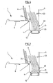
- the sensor 20 which is disposed at the bottom of the unstacking head 5 at the bottom of the chute 11 is here a mechanical flag sensor in the form of a retractable finger in the thickness of the head 5 to detect the presence of a shipment facing the lowest part (bottom) of the head 5.
- the sensor 20 is illustrated in more detail on the figure 4 . It provides a signal indicative of the presence of a consignment when it is sufficiently retracted into the head under the effect of the push of the foot of the current consignment in the direction of the direction 6 itself pressed by the stack of shipments bearing against each other in the chute 11.
- This sensor 20 has more particularly, in the rest position, a free end protruding from the unstacking head which has a profile bevel widening in the direction of the direction 6 and whose flat portion is flush with the bottom of the chute 11.
- the sensor 20 moves in the direction 6 against a return spring R and the signal that it provides, when retracted inside the unstacking head 5, can also be indicative of the distance on which it retracted with respect to its rest position and therefore a pressure magnitude.
- a return spring R we see on the figure 4 it is arranged below the lower line of perforated strips 9.
- the sensor 20 is adapted to measure the pressure exerted by all the items in the drop at the foot of the items.
- a pressure of 0.3 Newton of the feet of the shipments against the unstacking head disposes the shipments of the fall fan open on the top. Fetching shipments facilitates their separation and reduces the multiple catch rate.
- a control of the pressure of the feet of the items can be provided and the pressure can be adjusted by feeding the chute 11 in postal items.
- the sensor 21 is a reflection photoelectric cell disposed vertically above the sensor 20, for example 20 mm from the bottom of the chute, to detect the presence of a current shipment facing a first intermediate portion of the head above from the lower part of the head.
- the sensor 22 is a reflection photocell arranged vertically above the sensor 21, for example at 90 mm from the bottom of the chute, to detect the presence of a current shipment facing a second intermediate portion of the head above. of the first intermediate part. As visible on the figure 4 these two intermediate parts are at the level of the perforated strips 9.
- the sensors 20 and 21 are set to each provide a signal indicative of the presence of a shipment when this shipment is at a distance of less than about 4mm from the head 5 in the direction 6.
- the sensor 22 is set to provide a signal indicative of the presence of a shipment when this shipment is at a distance of less than about 8mm from the head 5 in the direction 6.
- the signals supplied by the sensors 20 to 22 are normally indicative of the presentation of the current item to be unstacked with respect to the unstacking head.
- the sensor 23 is a photoelectric barrier cell that operates along the unstacking head 5 and whose beam is oriented to cross the face of a shipment. This beam is drawn substantially in the direction 8 between a transmitter and a receiver of the sensor 23 at about 8 mm in front of the unstacking head 5 in the direction 6 and at a height of about 190 mm from the bottom of the chute 11.
- a single element of the sensor 23 (transmitter or receiver) mounted on a lateral side of the unstacking head opposite the side where the deformable wheels 10 are arranged.
- the other complementary element of the sensor 23 is disposed on the other lateral side of the head, here on the inlet cone side upstream of the motorized deformable wheels 10.
- the sensor is arranged to detect the presence of a flat object in said direction indicated by the arrow 8.
- the sensor 24 is also a photoelectric barrier cell identical to the sensor 23 but whose emitter and reflector are arranged at a height of approximately 112 mm with respect to the bottom of the chute and in the transition zone between the main conveyor 2 and the fall 11 on each side of the magazine 1.
- the signal provided by the sensor 24 is indicative of the presence of shipments in the chute.
- the sensor 25 may be a mechanical contact sensor arranged to detect the presence of the pallet 4 at the transition zone between the main conveyor 2 and the chute 11.
- two further sensors 26 and 27 are shown which are photoelectric barrier cells arranged vertically one below the other and whose beams are oriented in the direction indicated by the arrow 6 to detect the presence of shipments in the entry cone near and upstream of the deformable wheels 10.
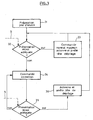
- FIG. 3 a simplified flowchart shows the operation of the unstacking device according to the invention with the sensors and more particularly the operation of the control unit 13.
- the control unit actuates all motorized drives for operation at a constant unstacking rate.
- the speeds of movement of the conveyor belt 2 and the pallet 4 are identical.
- the speed of movement of the belts of the conveyors 12 is slightly greater than that of the band 2 or the pallet.
- the speed of movement of the belts 9 is much greater than that of the belts of the conveyors 12.
- the speed of the belt 2 is 0.096 m / s
- that of the belts of the conveyors 12 is 0.152 m / s
- that of the perforated strips 9 is 1.5 m / s.
- the stack of shipments 3 singing then advances towards the unstacking head 5 and the first mailings to the front of the stack fall into the chute 11.
- the stack of shipments is split and the shipments on edge in the fall are placed in fan under the action of the faster movement of the conveyors 12 in the bottom of the fall and a first current to be unstacked is detected for example by the sensor 23.
- step 32 the process continues at step 32 where the signals S provided by the sensors are controlled by the control unit 13 to determine whether the current mail item to be unstacked has a proper presentation with respect to the unstacking head to be stripped without risk of damage or jam.
- step 33 the control unit 13 maintains in normal depilatory operation the belt conveyor 2, the pallet 4, the conveyors 12 and actuates the motorized drive perforated strips 9 and suction nozzles so as to depilate the shipment.
- the current sending is then serialized by passing between the deformable wheels 10, the motorized drive of the perforated strips 9 and the suction nozzles is stopped and the process loops on the step 32 for a new control of the S signals. loop process, shipments are unstacked at a constant rate of one mailing every 330 milliseconds.
- step 32 the signals S provided by the sensors are indicative of an inadequate presentation of the current mail with respect to the unstacking head 5
- the process continues in step 34 where the control unit 13 triggers a correction phase of the presentation of the current shipment relative to the unstacking head.
- the training motorized perforated strips 9 and suction nozzles being stopped the current shipment is not depilated.
- control unit 13 independently controls the motorized drives of the conveyor 2, the pallet 4 and the conveyors 12 of the chute so as to straighten the postal items which are in the chute 11 and thus correct the presentation of the current item to be unstacked.
- step 34 the unit 13 checks, in step 35, the signals S supplied by the sensors to the control unit 13 to determine whether the current mail is now adequate compared to the unstacking head.
- steps 34 and 35 can be performed almost simultaneously.
- step 35 the signals S of the sensors are indicative of an adequate presentation of the current item to be unstacked and that one is in the time window T compatible with a constant pitch between consecutive items at the output of the unstacking device, then the control unit 13 continues the process in step 36 by operating the motorized drive of the unstacking head (perforated strips and suction nozzles).
- the current to be despatched is then serialized between the deformable wheels 10 at the output of the unstacking device, the motorized drive of the perforated strips 9 and the suction nozzles is stopped and the normal unstacking operation is restored. The process then loops to step 32.
- step 35 if the signals S of the sensors are indicative of an inadequate presentation of the current mail item to be unstacked and / or that is outside the time window T, the process loops to the step 34 to continue the correction phase or adapt the correction according to the signals S.
- steps 34 and 35 are repeated as many times as necessary until a proper presentation of the current mail item to be popped up in the time window T is made, but it is preferable that beyond a certain period of time correction without obtaining an adequate presentation, an alarm is triggered to prevent the need for manual intervention.
- an inadequate presentation of the current item to be unstacked with respect to the unstacking head 5 is detected on the basis of a control of the signals supplied by the four sensors 20, 21, 22 and 23.
- a Proper presentation of the current mail item to be unstacked is detected on the basis of a control of the signals provided by the same sensors 20, 21, 22 and 23.
- the criteria for judging whether or not the current item to be unstuffed with respect to the unstacking head can be codified in a truth table as illustrated on the figure 12 .
- this truth table has been illustrated with on the left a very schematic representation of the current mail item to be displayed in profile in correspondence with the value of the signal supplied by the sensors 20 to 24.
- a signal with the value of "1” indicates a detection of the presence of a shipment while a signal at the value of "0" indicates the absence of detection of the presence of a shipment.
- the drives of the motorized drives of the belt conveyor 2, the pallet 4 and the secondary conveyors 12 are also shown as a function of the signals supplied by the sensors 20 to 24.
- the control unit 13 can react by actuating the motorized drive of the unstacking head only if the current mail is not already engaged in the entry cone between the deformable wheels 10 (detected by the sensors 26 and 27).
- the control unit 13 can also, on detection of collapsed shipments in the chute, do not actuate the motorized drive of the unstacking head during the time window T, the time to straighten these shipments by pushing them with shipments on the main conveyor. If the control unit 13 detects by the sensors that only the foot of the current item is poorly presented, it may not operate the motorized drive of the unstacking head during the time window T so that the conveyors 12 in the fall have time to restore the presentation of this current shipment.
- step 34 of the figure 3 The process of recovery of shipments in step 34 of the figure 3 will be better understood in the light of the presentation of different example cases below.
- This situation is detected by the control unit 13 because the sensor 22 produces a signal indicative of the absence of sending while the sensors 20, 21 and 23 each produce a signal indicative of the presence of a shipment. This situation corresponds to the third line of the truth table of the figure 12 .
- control unit 13 detects an unsuitable presentation of the current item to be unstacked and orders at step 34 a correction phase of the presentation of the current item. relative to the unstacking head.
- step 34 the control unit 13 controls the motorized drives of the conveyor 2 and the pallet 4 by passing them at a low speed of displacement at 0.096 m / s. At the same time, the control unit 13 suspends the motorized drive of the belt conveyors 12, since as indicated by the sensors 20 and 21 the foot of the current mailpiece is correctly pressed against the head 5, which has the effect of to straighten shipments in the fall because new shipments arrive from the main conveyor 2 pushed by pallet 4.
- the unit 13 controls, in step 35, the signals of the sensors.
- step 35 if the signals S of the sensors are indicative of an adequate presentation of the current item to be unstacked and which is in the time window T, the control unit 13 continues the process to step 36 by operating the motorized drive of the unstacking head (perforated strips and suction nozzles).
- the current to be despatched is then serialized between the deformable wheels 10 at the output of the unstacking device, the motorized drive of the perforated strips 9 and the suction nozzles is stopped and the normal unstacking operation is restored. The process then loops to step 32.
- step 35 if the signals S of the sensors are indicative of an unsuitable presentation of the current item to be unstacked, the process loops in step 34 to continue the correction phase or to adapt the correction to function of the signals S.
- the unit control 13 controls the belt conveyors 12 to pass in average speed to 0.152 m / s so as to straighten the shipments in the fall 11. This situation corresponds to the second line of the truth table of the figure 12 .
- Another similar situation would occur with sensors 20, 21 and 22 which each provide a signal indicative of the absence of a sending while the sensors 23 and 24 each provide a signal indicative of the presence of a shipment.
- This situation corresponds to inclined consignments in the left-hand part of the fall on the figure 5 .
- the control unit 13 in step 34 controls the belt conveyors 12 to pass them at an average speed of 0.152 m / s and controls the motorized drives of the conveyor 2 and the pallet 4 by passing them in small movement speed at 0.096 m / s.
- This situation corresponds to the fourth line of the truth table of the figure 12 .
- a particular situation would arise with sensors 21 and 22 which each provide a signal indicative of the absence of a sending while the sensors 20, 23 and 24 each provide a signal indicative of the presence of a shipment.
- the control unit 13 in step 34 controls the belt conveyors 12 to pass them in medium speed in reverse at 0.152 m / s and controls the motorized drives of the conveyor 2 and the pallet 4 in them. moving in low speed of displacement to 0.096 m / s.
- This situation corresponds to the fifth line of the truth table of the figure 12 .
- the sensor 24 detects the presence of a shipment.
- the control unit 13 thus detects an inadequate presentation of the current mail with respect to the unstacking head 5.
- the control unit 13 starts a correction phase consisting of simultaneously to interrupt the drive of the conveyor 2 for 25 milliseconds, change the speed of movement of the pallet in low speed to 0.096 m / s and interrupt the drive of the conveyors 12 of the chute. After the delay of 25 milliseconds, the unit 13 changes the speed of the belt conveyor 2 to 0.096 m / s.
- This correction phase causes a shift between the pallet 2 and the conveyor 2 at the top of the shipments both on the main conveyor 2 and in the chute 11.
- the unit 13 checks, in step 35, whether the signals S of the sensors are indicative of an adequate presentation of the current item and that one is in the time window T. In this case, at step 36, the control unit 13 actuates the motorized drive of the unstacking head and continues the process as previously described.
- step 35 if the signals S of the sensors are indicative of an inadequate presentation of the current send, the process loops in step 34 to continue the correction phase or to adapt the correction as a function of the signals. S.
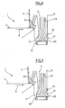
- FIG 7 another example of an inadequate presentation of the current item to be unstacked with respect to the unstacking head has been illustrated.
- the top of the shipments in the chute collapses backwards and at the same time the foot of the shipments in the fall collapses towards the rear.
- the sensors 20 and 23 each provide a signal indicative of the absence of a sending while the sensors 21, 22 and 24 each provide a signal indicative of the presence of a shipment.
- This situation corresponds to the sixth line of the truth table of the figure 12 .
- step 34 the control unit 13 triggers a correction phase of suspending the drive of the belt conveyor 2 for 25 milliseconds and then changes the speed of the conveyor 2 to 0.096 m / s.
- the speed of movement of the pallet 4 has changed to a low speed mode at 0.096 m / s while the speed of the conveyors 12 has increased to an average speed of 0.152 m / s. This has the effect on the one hand to straighten the top of the shipments in the fall and at the same time to advance the foot of the shipments to the unstacking head.
- the unit 13 checks, in step 35, whether the signals S of the sensors are indicative of an adequate presentation of the current item and that one is in the time window T and the process continues as described previously.
- FIG 8 another example of an inadequate presentation of the current item to be unstacked with respect to the unstacking head has been illustrated.
- the feet of the items in the chute are set back relative to the unstacking head.
- the sensors 20 and 21 each provide a signal indicative of the absence of a sending while the sensors 22 and 23 each provide a signal indicative of the presence of a shipment.
- the sensor 24 also provides a signal indicative of the absence of sending in the chute. In this case the fall is insufficiently fed with shipments.
- This situation corresponds to the ninth line of the truth table of the figure 12 .
- step 34 the control unit 13 triggers a correction phase consisting of moving the conveyor 2 and the pallet 4 at a low speed of 0.096 m / s while the conveyors 12 are changed to an average speed of 0.152 m / s. s
- the sensors 21 and 24 each provide a signal indicative of the absence of a sending while the sensors 20, 22 and 23 each provide a signal indicative of the presence of a shipment. This situation corresponds to the tenth line of the truth table of the figure 12 .
- step 34 the control unit 13 passes the pallet 4 and the conveyor 2 of the main magazine in low speed at 0.096 m / s while it controls a reverse of the conveyors 12 at an average speed of 0.152 m / s.
- the sensors 20, 21 provide a signal indicative of the absence of a sending while the sensors 22, 23 and 24 each provide a signal indicative of the presence of a shipment.
- This situation corresponds to the eleventh line of the truth table of the figure 12 .
- step 34 the control unit 13 passes the conveyor 2 and the pallet 4 in low speed at 0.096 m / s for 25 milliseconds and then interrupts their operation. At the same time, it passes conveyors 12 at an average speed of 0.152 m / s to straighten shipments in the fall without fueling the drop in shipments.
- the presentation of the items is similar to the situation of the figure 10 but the foot of the shipments collapses on the front.
- the sensor 21 provides a signal indicative of the absence of a sending while the sensors 20, 22, 23 and 24 each provide a signal indicative of the presence of a shipment. This situation corresponds to the twelfth line of the truth table of the figure 12 .
- control unit 13 passes the conveyor 2 and the pallet 4 at low speed for 25 milliseconds and then interrupts their operation. At the same time, it passes the conveyors 12 in reverse at a speed of 0.152 m / s to straighten the shipments in the fall.
- the invention is not limited to the sole embodiment of the unstacking device described above. In particular, one would not depart from the scope of the invention by modifying the detail of the sensors, by modifying the number of sensors, by applying different corrections in response to the signals provided by the sensors.
Abstract
Description
L'invention concerne un dispositif de dépilage d'objets plats comprenant un magasin d'alimentation motorisé commandé pour déplacer des objets plats en pile sur chant face à une tête de dépilage avec un entraînement motorisé. L'entraînement motorisé comprenant une bande perforée et une chambre à dépression est actionné pour séparer un premier objet courant de la pile et l'entraîner dans une direction transversale à la direction de déplacement de la pile d'objets plats.The invention relates to a device for unstacking flat objects comprising a power supply magazine controlled to move flat objects in stack on edge facing an unstacking head with a motorized drive. The motorized drive comprising a perforated band and a vacuum chamber is operated to separate a first current object from the stack and drive it in a direction transverse to the moving direction of the stack of flat objects.
L'invention concerne plus particulièrement un dispositif de dépilage d'envois postaux, tels que lettres et objets plats dits de grand format, dans une machine de tri postal par exemple.The invention more particularly relates to a device for unstacking postal items, such as letters and flat objects of large format, in a postal sorting machine for example.
Du document de brevet
Les envois postaux de la pile sont maintenus latéralement par une rive de taquage 7 qui s'étend dans un plan sensiblement vertical le long d'un bord du convoyeur à bande 2. La tête de dépilage 5 sensiblement plane s'étend dans un plan vertical transversal à la direction indiquée par la flèche 6 de déplacement de la pile d'envois 3 sur le convoyeur à bande 2 et est apte à séparer le premier envoi courant à l'avant de la pile dans la direction transversale indiquée par la flèche 8 perpendiculaire à la flèche 6.The postal items of the stack are held laterally by a jogging
La tête de dépilage 5 comprend deux ouvertures sensiblement rectangulaires dans lesquelles une bande perforée 9 et une ou plusieurs chambres à dépression ou buses d'aspiration (non montrées) sont entraînées par une motorisation, coopérant pour saisir par aspiration le premier envoi de la pile et pour le déplacer selon la direction indiquée par la flèche 8.The
En fonctionnement, la pile d'envois postaux 3 disposée dans le magasin principal 1 est déplacée par les entraînements motorisés de type pas à pas du convoyeur à bande 2 et de la palette 4 qui sont actionnés à la même vitesse. Le premier envoi à l'avant de la pile d'envois est ainsi amené en appui contre la tête de dépilage 5 de sorte que cet envoi postal courant de la pile est plaqué contre la tête de dépilage 5 et est séparé de la pile par l'effet combiné de l'aspiration des buses et du mouvement de la bande perforée 9. L'envoi postal est ensuite pincé entre deux roues déformables 10 disposées dans le prolongement de la tête 5. Ces roues 10 sont motorisées pour convoyer l'envoi courant en aval du dispositif de dépilage. Elles sont constituées d'une matière élastomère élastiquement déformable de sorte à pouvoir s'adapter à différentes épaisseurs d'envois postaux.In operation, the stack of
Pour la suite du processus de tri, il est nécessaire que les envois postaux soient sérialisés en sortie du dispositif de dépilage avec un pas constant entre envois consécutifs. L'entraînement de la bande perforée 9 et des buses d'aspiration est donc actionné et arrêté à une cadence constante.For the rest of the sorting process, it is necessary for the postal items to be serialized at the output of the unstacking device with a constant pitch between consecutive items. The driving of the
Ce processus de dépilage se répète au fur et à mesure qu'un nouvel envoi postal à l'avant de la pile est présenté face à la tête de dépilage 5.This unstacking process is repeated as a new mailing at the front of the pile is presented in front of the
Dans le dispositif du document
De manière générale dans une machine de tri postal, les envois postaux sortant du dépileur sont convoyés en série sur chant pour être amenés devant une tête de lecture. La tête de lecture réalise l'acquisition d'une image de chaque envoi sérialisé pour un décodage automatique de l'adresse de distribution ou d'acheminement de l'envoi par un traitement OCR ("Optical Character Recognition" - Reconnaissance Automatique de Caractères). Les envois postaux sont ensuite dirigés vers des sorties de tri correspondant aux adresses décodées automatiquement.Generally in a postal sorting machine, postal items leaving the unstacker are conveyed in series on edge to be brought in front of a read head. The read head acquires an image of each serialized send for an automatic decoding of the distribution or routing address of the sending by OCR processing ("Optical Character Recognition") . The postal items are then sent to sorting outlets corresponding to the automatically decoded addresses.
Dans ce type de dispositif de dépilage, on a constaté qu'une proportion importante d'envois postaux ne se présentent pas de façon adéquate face à la tête de dépilage au moment de leur dépilage ce qui a pour conséquence que ces envois peuvent être détériorés ou déchirés lorsqu'ils sont pris en charge par les roues 10 par exemple. Il peut même arriver que ces envois provoquent un bourrage dans le dispositif de dépilage nécessitant l'intervention d'un opérateur de maintenance et l'arrêt du dispositif de dépilage. L'intervention est coûteuse et ralentit le processus global de tri. Cette situation peut être particulièrement fréquente avec des envois postaux ouverts du type brochures publicitaires, magazines.., etc.In this type of unstacking device, it has been found that a large proportion of postal items do not present themselves adequately in front of the unstacking head at the time of unstacking, which has the consequence that these items can be damaged or torn when supported by the
Le document de brevet
Dans le document
Toutefois, les dispositions indiquées ci-dessus n'éliminent pas encore complètement les situations de détérioration des envois postaux ou les situations de bourrage dans le dispositif de dépilage, par exemple quand des envois postaux très souples ont tendance à s'effondrer dans la chute.However, the provisions indicated above do not yet completely eliminate the situations of deterioration of postal items or stuffing situations in the unstacking device, for example when very flexible postal items tend to collapse in the fall.
Le document de brevet
Dans le document
Avec le dispositif du document
On connaît également du document
Le but de la présente invention est donc d'améliorer encore plus un dispositif de dépilage d'objets plats pour éviter la détérioration de ces objets plats et le bourrage du dispositif de dépilageThe object of the present invention is therefore to further improve a device for unstacking flat objects to prevent deterioration of these flat objects and the stuffing of the unstacking device
A cet effet, l'invention a pour objet un dispositif de dépilage d'objets plats comprenant les caracteristiques de la revendication 1.For this purpose, the subject of the invention is a device for unstacking flat objects comprising the features of
Avec cet agencement, on comprend que le dépilage de l'envoi courant dans une pile d'envois postaux peut intervenir seulement quand celui-ci se présente de façon adéquate par rapport à la tête de dépilage, ce qui permet d'éviter les situations de détérioration des envois postaux et/ou de bourrage.With this arrangement, it is understood that the unstacking of the current mail in a stack of postal items can intervene only when it is adequately present with respect to the unstacking head, which avoids the situations of deterioration of postal items and / or stuffing.
Le dispositif de dépilage selon l'invention peut inclure les particularités suivantes:
- la pluralité de capteurs comprend un premier capteur disposé dans la tête de dépilage pour détecter la présence d'une partie inférieure de l'objet courant face à la tête de dépilage;
- la pluralité de capteurs comprend un second capteur disposé dans la tête de dépilage pour détecter la présence d'une première partie intermédiaire de l'objet courant face à la tête de dépilage, ladite première partie intermédiaire étant située au-dessus de ladite partie inférieure de l'objet courant ;
- la pluralité de capteurs comprend un troisième capteur disposé dans la tête de dépilage pour détecter la présence d'une seconde partie intermédiaire de l'objet courant face à la tête de dépilage, cette seconde partie intermédiaire étant située au-dessus de ladite première partie intermédiaire de l'objet courant;
- la pluralité de capteurs comprend en outre un quatrième capteur disposé pour détecter la présence d'un objet plat selon ladite direction transversale à la direction de déplacement de la pile d'objets plats.
- the plurality of sensors comprises a first sensor disposed in the unstacking head to detect the presence of a lower portion of the current object facing the unstacking head;
- the plurality of sensors comprises a second sensor disposed in the unstacking head for detecting the presence of a first intermediate portion of the current object facing the unstacking head, said first intermediate portion being located above said lower part of the current object;
- the plurality of sensors comprises a third sensor disposed in the unstacking head to detect the presence of a second intermediate portion of the current object facing the unstacking head, this second intermediate portion being located above said first intermediate portion the current object;
- the plurality of sensors further comprises a fourth sensor arranged to detect the presence of a flat object in said direction transverse to the direction of movement of the stack of flat objects.
Selon un mode de réalisation particulier de l'invention, le premier capteur est un capteur mécanique drapeau, le second capteur est un capteur optique à réflexion, et le troisième capteur est un capteur optique à réflexion et le quatrième capteur est un capteur de barrage optique, les premier, second et troisième capteurs sont alignés verticalement dans la tête de dépilage.According to a particular embodiment of the invention, the first sensor is a flag mechanical sensor, the second sensor is a reflection optical sensor, and the third sensor is a reflection optical sensor and the fourth sensor is an optical barrier sensor the first, second and third sensors are aligned vertically in the unstacking head.
Dans un mode de réalisation particulier de l'invention, le magasin d'alimentation comprend une chute disposée entre un convoyeur principal avec un entraînement motorisé et la tête de dépilage ainsi qu'une palette avec un entraînement motorisé, ladite palette étant apte à être déplacée le long du convoyeur principal, la chute étant munie de convoyeurs secondaires avec un entraînement motorisé, l'unité de commande agissant sur les entraînements motorisés du convoyeur principal, de la palette et des convoyeurs secondaires pour présenter de façon adéquate l'objet courant par rapport à la tête de dépilage.In a particular embodiment of the invention, the feed magazine comprises a chute arranged between a main conveyor with a motorized drive and the unstacking head and a pallet with a motorized drive, said pallet being able to be moved along the main conveyor, the chute being provided with secondary conveyors with a motorized drive, the control unit acting on the motorized drives of the main conveyor, the pallet and the secondary conveyors to adequately present the current object in relation to the main conveyor at the unstacking head.
On doit comprendre que le convoyeur principal, la palette motorisée et les convoyeurs secondaires dans la chute sont prévus pour être commandés de façon asynchrone par l'unité de commande qui est en outre agencée pour changer la vitesse et le sens des entraînements motorisés du magasin d'alimentation pour présenter l'objet courant de façon adéquate.It should be understood that the main conveyor, the motorized pallet and the secondary conveyors in the chute are provided to be asynchronously controlled by the control unit which is further arranged to change the speed and direction of the motorized drives of the store. power supply to present the current object adequately.
Selon un autre mode de réalisation particulier de l'invention, l'unité de commande est agencée pour déclencher une alarme à l'issue d'une certaine durée pendant laquelle l'unité de commande 13 agit sur les entraînements motorisés du convoyeur principal, de la palette et des convoyeurs secondaires sans obtenir une présentation adéquate de l'objet courant par rapport à la tête de dépilage.According to another particular embodiment of the invention, the control unit is arranged to trigger an alarm at the end of a certain period during which the
L'invention s'étend à une machine de traitement d'envois postaux comprenant un tel dispositif de dépilage.The invention extends to a machine for processing postal items comprising such an unstacking device.
Le dispositif d'alimentation selon l'invention s'applique à des objets plats, par exemple des envois postaux plats petits et grands formats mais peut également trouver une application dans d'autres domaines de traitement d'objets plats tels que des livres, des chèques ou autres.The feeding device according to the invention applies to flat objects, for example small and large format flat mailpieces, but can also find application in other areas of processing of flat objects such as books, books and magazines. checks or other.
L'invention sera mieux comprise à la lecture de la description qui suit en relation avec les dessins. Cette description n'est donnée qu'à titre d'exemple indicatif et nullement limitatif de l'invention.The invention will be better understood on reading the description which follows in relation to the drawings. This description is given as an indicative and non-limiting example of the invention.
La
La
La
La
La
La
La
La
La
La
La
La
La
La
Ce dispositif de dépilage sert à sérialiser des envois en amont de convoyeurs en série d'envois postaux dans lesquels les envois sont séparés deux à deux avec un pas normalement constant. Les entraînements motorisés des roues déformables 10 entre lesquelles sont pincés les envois sérialisés peuvent être commandés à une vitesse variable pour rattraper si nécessaire des écarts de pas entre envois consécutifs. Cet agencement à vitesse variable constitue un système de synchronisation garantissant un pas constant.This unstacking device is used to serialize shipments upstream of serial conveyors of postal items in which the items are separated in pairs with a normally constant pitch. The motorized drives of the
Avantageusement, ce système de synchronisation autorise la réalisation de certaines opérations de correction pendant une fenêtre de temps T compatible avec l'exigence d'un pas constant entre envois consécutifs en sortie du dispositif de dépilage.Advantageously, this synchronization system authorizes the performance of certain correction operations during a time window T compatible with the requirement of a constant pitch between consecutive items at the output of the unstacking device.
Le dispositif de dépilage 1 comprend un magasin d'alimentation principal 1 avec un convoyeur à bande 2 avec un entraînement motorisé sur lequel des envois postaux 3 sont disposés en pile sur chant à l'avant d'une palette 4 avec un entraînement motorisé qui s'étend sensiblement dans un plan vertical en étant légèrement inclinée pour soutenir l'arrière de la pile d'envois.The
Le convoyeur à bande 2 et la palette 4 déplacent la pile d'envois 3 sur chant en direction de la tête de dépilage 5 selon la direction 6.The
On a représenté également le long du convoyeur à bande 2, une rive de taquage 7 contre laquelle les bords latéraux des envois sont alignés.There is also shown along the
Sur la
Le fond de cette chute 11 est pourvu d'un ensemble de convoyeurs secondaires 12 avec un entraînement motorisé, par exemple ici quatre convoyeurs à bande, qui déplacent les envois sur chant dans la chute selon la direction 6 en direction de la tête de dépilage 5.The bottom of this
La tête de dépilage 5 avec un entraînement motorisé s'étend verticalement depuis le fond de la chute 11 jusqu'à une hauteur suffisante correspondant au moins à la hauteur maximale des envois postaux à dépiler.The
La tête de dépilage 5 sous la forme d'une tôle est munie ici de deux ouvertures de forme rectangulaire disposées côte à côte dans la direction 8. Dans chacune de ces ouvertures, une bande perforée 9 sans fin coopère avec des chambres à dépression ou buses d'aspiration (non montrées) pour saisir et déplacer selon la direction 8 un envoi courant de la pile qui fait face à la tête.The
Selon l'invention, les entraînements motorisés du convoyeur à bande 2, de la palette 4, des convoyeurs secondaires 12 et de la tête de dépilage (bandes perforées 9 et buses d'aspiration) sont prévus pour être commandés de façon indépendante les uns des autres mais peuvent bien entendu être synchronisés l'un par rapport à l'autre par une unité de commande 13, par exemple un processeur de traitement de données programmable.According to the invention, the motorized drives of the
Sur la
Selon l'invention, le dispositif de dépilage comprend un ensemble de capteurs qui fournissent chacun un signal de détection à l'unité de commande 13. Sur la
Plus particulièrement sur la
Le capteur 20 qui est disposé au plus bas de la tête de dépilage 5 au niveau du fond de la chute 11 est ici un capteur mécanique drapeau sous la forme d'un doigt rétractable dans l'épaisseur de la tête 5 pour détecter la présence d'un envoi face à la partie la plus inférieure (bas) de la tête 5.The
Le capteur 20 est illustré plus en détail sur la
Le capteur 20 est adapté pour mesurer la pression exercée par l'ensemble des envois dans la chute au niveau du pied des envois. Une pression de 0.3 Newton des pieds des envois contre la tête de dépilage dispose les envois de la chute en éventail ouvert sur le haut. La mise en éventail des envois facilite leur séparation et réduit le taux de prise multiple. Un contrôle de la pression des pieds des envois peut être prévu et la pression peut être ajustée en alimentant la chute 11 en envois postaux.The
Le capteur 21 est une cellule photoélectrique à réflexion disposée verticalement au-dessus du capteur 20, par exemple à 20 mm du fond de la chute, pour détecter la présence d'un envoi courant face à une première partie intermédiaire de la tête au-dessus de la partie inférieure de la tête.The
Le capteur 22 est une cellule photoélectrique à réflexion disposée verticalement au-dessus du capteur 21, par exemple à 90 mm du fond de la chute, pour détecter la présence d'un envoi courant face à une seconde partie intermédiaire de la tête au-dessus de la première partie intermédiaire. Comme visible sur la
Les capteurs 20 et 21 sont réglés pour fournir chacun un signal indicatif de la présence d'un envoi quand cet envoi est à une distance inférieure à environ 4mm de la tête 5 selon la direction 6.The
Le capteur 22 est réglé pour fournir un signal indicatif de la présence d'un envoi quand cet envoi est à une distance inférieure à environ 8mm de la tête 5 selon la direction 6.The
On comprend donc que les signaux fournis par les capteurs 20 à 22 sont normalement indicatifs ensemble de la présentation de l'envoi courant à dépiler par rapport à la tête de dépilage.It will thus be understood that the signals supplied by the
Sur la
Le capteur 23 est une cellule barrage photoélectrique qui fonctionne le long de la tête de dépilage 5 et dont le faisceau est orienté pour croiser la face d'un envoi. Ce faisceau est tiré sensiblement selon la direction 8 entre un émetteur et un récepteur du capteur 23 à environ 8 mm devant la tête de dépilage 5 selon la direction 6 et à une hauteur d'environ 190 mm du fond de la chute 11.The
Sur la
Le capteur 24 est également une cellule barrage photoélectrique identique au capteur 23 mais dont l'émetteur et le réflecteur sont disposés à une hauteur d'environ 112 mm par rapport au fond de la chute et dans la zone de transition entre le convoyeur principal 2 et la chute 11 de chaque coté du magasin 1. Le signal fourni par le capteur 24 est indicatif de la présence d'envois dans la chute.The
Le capteur 25 peut être un capteur à contact mécanique disposé pour détecter la présence de la palette 4 au niveau de la zone de transition entre le convoyeur principal 2 et la chute 11.The
Enfin sur la
L'utilisation de ces différents capteurs sera précisée plus loin pour différentes situations de présentation inadéquates des envois postaux face à la tête de dépilage.The use of these different sensors will be specified below for different situations of inadequate presentation of mail items facing the unstacking head.
Sur la
Dans l'étape 31 de préparation, des envois postaux sont préalablement placés par l'opérateur en pile sur chant sur le convoyeur principal 2 à l'avant de la palette 4. L'unité de commande actionne tous les entraînements motorisés pour un fonctionnement à une cadence de dépilage constante. Les vitesses de déplacement de la bande du convoyeur 2 et de la palette 4 sont identiques. La vitesse de déplacement des bandes des convoyeurs 12 est légèrement plus grande que celle de la bande 2 ou de la palette. La vitesse de déplacement des bandes 9 est bien plus grande que celle des bandes des convoyeurs 12. A titre d'exemple, en mode de dépilage normal, la vitesse de la bande 2 est de 0.096 m/s, celle des bandes des convoyeurs 12 est de 0.152 m/s et celle des bandes perforées 9 est de 1.5 m/s.In the
La pile d'envois 3 sur chant avance donc en direction de la tête de dépilage 5 et des premiers envois postaux à l'avant de la pile tombent dans la chute 11. Dans cet exemple, la pile d'envois est donc fractionnée et les envois sur chant dans la chute se placent en éventail sous l'action du mouvement plus rapide des convoyeurs 12 dans le fond de la chute et un premier envoi courant à dépiler est détecté par exemple par le capteur 23.The stack of
A ce stade, le processus se poursuit à l'étape 32 où les signaux S fournis par les capteurs sont contrôlés par l'unité de commande 13 pour déterminer si l'envoi courant à dépiler a une présentation adéquate par rapport à la tête de dépilage pour être dépilé sans risque de détérioration ou de bourrage.At this point, the process continues at
Si, à l'étape 32, les signaux S des capteurs sont indicatifs d'une présentation adéquate de l'envoi courant et que l'on se trouve dans la fenêtre de temps T compatible avec un pas constant, alors à l'étape 33, l'unité de commande 13 maintient en fonctionnement de dépilage normal le convoyeur à bande 2, la palette 4, les convoyeurs 12 et actionne l'entraînement motorisé des bandes perforées 9 et des buses d'aspiration de sorte à dépiler l'envoi. L'envoi courant est alors sérialisé en passant entre les roues déformables 10, l'entraînement motorisé des bandes perforées 9 et des buses d'aspiration est arrêté et le processus boucle sur l'étape 32 pour un nouveau contrôle des signaux S. Dans ce processus en boucle, les envois sont dépilés à une cadence constante d'un envoi postal toutes les 330 millisecondes.If, in
Si maintenant, dans l'étape 32, les signaux S fournis par les capteurs sont indicatifs d'une présentation non adéquate de l'envoi courant par rapport à la tête de dépilage 5, le processus se poursuit à l'étape 34 où l'unité de commande 13 enclenche une phase de correction de la présentation de l'envoi courant par rapport à la tête de dépilage. On comprend que, l'entraînement motorisé des bandes perforées 9 et des buses d'aspiration étant arrêté l'envoi courant n'est pas dépilé.If now, in
Pour effectuer cette correction, selon l'invention l'unité de commande 13 contrôle indépendamment les entraînements motorisés du convoyeur 2, de la palette 4 et des convoyeurs 12 de la chute de façon à redresser les envois postaux qui se trouvent dans la chute 11 et ainsi corriger la présentation de l'envoi courant à dépiler.To carry out this correction, according to the invention the
La manière dont le redressement est opéré est détaillée plus loin.The manner in which the adjustment is made is detailed below.
Pendant la phase de correction enclenchée à l'étape 34, l'unité 13 contrôle, à l'étape 35, les signaux S fournis par les capteurs à l'unité de commande 13 pour déterminer si l'envoi courant se présente maintenant de manière adéquate par rapport à la tête de dépilage. En pratique, les étapes 34 et 35 peuvent être réalisées en quasi-simultanéité.During the correction phase engaged in
Si à l'étape 35, les signaux S des capteurs sont indicatifs d'une présentation adéquate de l'envoi courant à dépiler et que l'on se trouve dans la fenêtre de temps T compatible avec un pas constant entre envois consécutifs en sortie du dispositif de dépilage, alors l'unité de commande 13 poursuit le processus à l'étape 36 en actionnant l'entraînement motorisé de la tête de dépilage (bandes perforées et buses d'aspiration).If in
L'envoi courant à dépiler est alors sérialisé entre les roues déformables 10 en sortie du dispositif de dépilage, l'entraînement motorisé des bandes perforées 9 et des buses d'aspiration est arrêté et le fonctionnement de dépilage normal est rétablit. Le processus boucle ensuite à l'étape 32.The current to be despatched is then serialized between the
A l'étape 35, si les signaux S des capteurs sont indicatifs d'une présentation non adéquate de l'envoi courant à dépiler et/ou que l'on se trouve en dehors de la fenêtre de temps T, le processus boucle à l'étape 34 pour continuer la phase de correction ou adapter la correction en fonction des signaux S.In
Par conséquent, les étapes 34 et 35 sont répétées autant de fois que nécessaire jusqu'à obtenir une présentation adéquate de l'envoi courant à dépiler dans la fenêtre de temps T mais il est préférable qu'au-delà d'une certaine durée de correction sans obtention d'une présentation adéquate, une alarme soit déclenchée pour prévenir la nécessité d'une intervention manuelle.Therefore, steps 34 and 35 are repeated as many times as necessary until a proper presentation of the current mail item to be popped up in the time window T is made, but it is preferable that beyond a certain period of time correction without obtaining an adequate presentation, an alarm is triggered to prevent the need for manual intervention.
Selon l'invention, une présentation non adéquate de l'envoi courant à dépiler par rapport à la tête de dépilage 5 est détectée sur la base d'un contrôle des signaux fournis par les quatre capteurs 20, 21, 22 et 23. Inversement, une présentation adéquate de l'envoi courant à dépiler est détectée sur la base d'un contrôle des signaux fournis par les mêmes capteurs 20, 21, 22 et 23.According to the invention, an inadequate presentation of the current item to be unstacked with respect to the
Les critères d'appréciation de la présentation adéquate ou non de l'envoi courant à dépiler par rapport à la tête de dépilage peuvent être codifiés dans une table de vérité telle qu'illustrée sur la
Sur la
Selon certaines situations de présentations non adéquates détectées par les capteurs, l'unité de commande 13 peut réagir en actionnant l'entraînement motorisé de la tête de dépilage seulement si l'envoi courant n'est pas déjà engagé dans le cône d'entrée entre les roues déformables 10 (détecté par les capteurs 26 et 27). L'unité de commande 13 peut également, sur détection des envois écroulés dans la chute, ne pas actionner l'entraînement motorisé de la tête de dépilage pendant la fenêtre de temps T, le temps de redresser ces envois en les poussant avec les envois sur le convoyeur principal. Si l'unité de commande 13 détecte par les capteurs que seulement le pied de l'envoi courant est mal présenté, elle peut ne pas actionner l'entraînement motorisé de la tête de dépilage pendant la fenêtre de temps T pour que les convoyeurs 12 dans la chute aient le temps de rétablir la présentation de cet envoi courant.According to some unsuitable presentation situations detected by the sensors, the
Le processus de redressement des envois dans l'étape 34 de la
Sur la
Cette situation est détectée par l'unité de commande 13 du fait que le capteur 22 produit un signal indicatif de l'absence d'envoi tandis que les capteurs 20, 21 et 23 produisent chacun un signal indicatif de la présence d'un envoi. Cette situation correspond à la troisième ligne de la table de vérité de la
En se reportant à la
A l'étape 34, l'unité de commande 13 contrôle les entraînements motorisés du convoyeur 2 et de la palette 4 en les passant en petite vitesse de déplacement à 0.096 m/s. En même temps, l'unité de commande 13 suspend l'entraînement motorisé des convoyeurs à bande 12, puisque comme indiqué par les capteurs 20 et 21 le pied de l'envoi courant est correctement plaqué contre la tête 5, ce qui a pour effet de redresser les envois dans la chute du fait que des envois nouveaux arrivent du convoyeur principal 2 poussés par la palette 4.In
Pendant la phase de correction, l'unité 13 contrôle, à l'étape 35, les signaux des capteurs. A l'étape 35, si les signaux S des capteurs sont indicatifs d'une présentation adéquate de l'envoi courant à dépiler et que l'on se trouve dans la fenêtre de temps T, l'unité de commande 13 poursuit le processus à l'étape 36 en actionnant l'entraînement motorisé de la tête de dépilage (bandes perforées et buses d'aspiration).During the correction phase, the
L'envoi courant à dépiler est alors sérialisé entre les roues déformables 10 en sortie du dispositif de dépilage, l'entraînement motorisé des bandes perforées 9 et des buses d'aspiration est arrêté et le fonctionnement de dépilage normal est rétablit. Le processus boucle ensuite à l'étape 32.The current to be despatched is then serialized between the
Par contre, à l'étape 35, si les signaux S des capteurs sont indicatifs d'une présentation non adéquate de l'envoi courant à dépiler, le processus boucle à l'étape 34 pour continuer la phase de correction ou adapter la correction en fonction des signaux S.On the other hand, in
Dans une situation non illustrée où les capteurs 21 et 23 fournissent un signal indicatif de la présence d'un envoi tandis que les capteurs 20 et 22 fournissent un signal indicatif de l'absence d'un envoi, à l'étape 34 l'unité de commande 13 contrôle les convoyeurs à bande 12 pour les passer en vitesse moyenne à 0,152 m/s de façon à redresser les envois dans la chute 11. Cette situation correspond à la deuxième ligne de la table de vérité de la
Une autre situation analogue se présenterait avec des capteurs 20, 21 et 22 qui fournissent chacun un signal indicatif de l'absence d'un envoi tandis que les capteurs 23 et 24 fournissent chacun un signal indicatif de la présence d'un envoi. Cette situation correspond à des envois inclinés dans la partie à gauche de la chute sur la
Une situation particulière se présenterait avec des capteurs 21 et 22 qui fournissent chacun un signal indicatif de l'absence d'un envoi tandis que les capteurs 20, 23 et 24 fournissent chacun un signal indicatif de la présence d'un envoi. Dans ce cas, l'unité de commande 13 à l'étape 34 contrôle les convoyeurs à bande 12 pour les passer en vitesse moyenne en marche arrière à 0,152 m/s et contrôle les entraînements motorisés du convoyeur 2 et de la palette 4 en les passant en petite vitesse de déplacement à 0.096 m/s. Cette situation correspond à la cinquième ligne de la table de vérité de la
Sur la
Dans l'exemple de la
Cette phase de correction provoque un décalage entre la palette 2 et le convoyeur 2 relevant le haut des envois à la fois sur le convoyeur principal 2 et dans la chute 11.This correction phase causes a shift between the
Pendant la phase de correction, l'unité 13 contrôle, à l'étape 35, si les signaux S des capteurs sont indicatifs d'une présentation adéquate de l'envoi courant et que l'on se trouve dans la fenêtre de temps T. Dans ce cas, à l'étape 36, l'unité de commande 13 actionne l'entraînement motorisé de la tête de dépilage et poursuit le processus comme décrit précédemment.During the correction phase, the
Par contre, a l'étape 35, si les signaux S des capteurs sont indicatifs d'une présentation non adéquate de l'envoi courant le processus boucle à l'étape 34 pour continuer la phase de correction ou adapter la correction en fonction des signaux S.On the other hand, in
Sur la
Dans cette situation, les capteurs 20 et 23 fournissent chacun un signal indicatif de l'absence d'un envoi tandis que les capteurs 21, 22 et 24 fournissent chacun un signal indicatif de la présence d'un envoi. Cette situation correspond à la sixième ligne de la table de vérité de la
A l'étape 34, l'unité de commande 13 enclenche une phase de correction consistant à suspendre l'entraînement du convoyeur à bande 2 pendant 25 millisecondes et ensuite passe la vitesse du convoyeur 2 à 0,096 m/s. En même temps la vitesse de déplacement de la palette 4 est passée en mode petite vitesse à 0,096 m/s tandis que la vitesse des convoyeurs 12 est passée en vitesse moyenne à 0,152 m/s. Ceci a pour effet d'une part de redresser le haut des envois dans la chute et en même temps de faire avancer le pied des envois vers la tête de dépilage.In
Pendant la phase de correction, l'unité 13 contrôle, à l'étape 35, si les signaux S des capteurs sont indicatifs d'une présentation adéquate de l'envoi courant et que l'on se trouve dans la fenêtre de temps T et le processus se poursuit comme décrit précédemment.During the correction phase, the
Sur la
A l'étape 34, l'unité de commande 13 enclenche une phase de correction consistant à faire passer le convoyeur 2 et la palette 4 en petite vitesse à 0,096 m/s tandis que les convoyeurs 12 sont passés en vitesse moyenne à 0,152 m/sIn
Ceci a pour effet d'alimenter la chute 11 en envois en tassant ces envois dans la chute. Il en résulte un redressement de l'envoi courant à dépiler.This has the effect of feeding the
Sur la
Dans cet exemple, les capteurs 21 et 24 fournissent chacun un signal indicatif de l'absence d'un envoi tandis que les capteurs 20, 22 et 23 fournissent chacun un signal indicatif de la présence d'un envoi. Cette situation correspond à la dixième ligne de la table de vérité de la
A l'étape 34, l'unité de commande 13 fait passer la palette 4 et le convoyeur 2 du magasin principal en petite vitesse à 0.096 m/s tandis qu'elle commande une marche arrière des convoyeurs 12 à la vitesse moyenne de 0.152 m/s.In
Ceci a pour effet d'une part d'alimenter la chute 11 en envois et de déplacer vers l'arrière le pied des envois déjà présents dans la chute, redressant ainsi l'ensemble des envois dans la chute 11.This has the effect on the one hand to feed the
Sur la
Dans ce cas d'exemple, les capteurs 20, 21 fournissent un signal indicatif de l'absence d'un envoi tandis que les capteurs 22, 23 et 24 fournissent chacun un signal indicatif de la présence d'un envoi. Cette situation correspond à la onzième ligne de la table de vérité de la
Dans cet exemple, la chute est trop alimentée en envois qui s'affaissent dans leur partie inférieure.In this example, the fall is too much fed with mail that collapses in their lower part.
A l'étape 34, l'unité de commande 13 fait passer le convoyeur 2 et la palette 4 en petite vitesse à 0,096 m/s pendant 25 millisecondes et interrompt ensuite leur fonctionnement. En même temps, elle fait passer les convoyeurs 12 en vitesse moyenne à 0,152 m/s pour redresser les envois dans la chute sans alimenter plus la chute en envois.In
Sur la
Dans cette situation, l'unité de commande 13 passe le convoyeur 2 et la palette 4 en petite vitesse pendant 25 millisecondes et interrompt ensuite leur fonctionnement. En même temps, elle passe les convoyeurs 12 en marche arrière à la vitesse de 0,152 m/s pour redresser les envois dans la chute.In this situation, the
Il est entendu que l'invention ne se limite pas à la seule forme de réalisation du dispositif de dépilage décrit ci-dessus. En particulier, on ne s'éloignerait pas du cadre de l'invention en modifiant le détail des capteurs, en modifiant le nombre de capteurs, en appliquant des corrections différentes en réponse aux signaux fournis par les capteurs.It is understood that the invention is not limited to the sole embodiment of the unstacking device described above. In particular, one would not depart from the scope of the invention by modifying the detail of the sensors, by modifying the number of sensors, by applying different corrections in response to the signals provided by the sensors.
Claims (10)
- An unstacker device for unstacking flat objects, which device comprises a motor-driven feed magazine controlled so as to move flat objects in a stack and on edge facing an unstacking head (5) provided with a motor-driven drive having a perforated belt and a suction chamber, which motor driven drive is actuated so as to separate a current first object from the stack and so as to eject it in a direction that is transverse to the direction in which the stack of flat objects is moved, in which device the motor-driven drive is actuated and stopped each time a current object is unstacked, and the stack of flat objects is straightened up in the magazine in response to detection of signals delivered by a plurality of sensors disposed in the unstacking head, a first sensor (20) being disposed to detect presence of a bottom portion of the current object facing the unstacking head (5), a second sensor (21) being disposed to detect presence of a first intermediate portion of the current object facing the unstacking head (5), said first intermediate portion being situated above said bottom portion of the current object, characterized in that a third sensor (22) is disposed to detect presence of a second intermediate portion of the current object facing the unstacking head, said second intermediate portion being situated above said first intermediate portion of the current object, said sensors (20,21,22) being disposed in the unstacking head in a manner such as to deliver signals indicating that said current object is presented appropriately relative to the unstacking head (5), and in that the drive of the unstacking head is actuated if the signals indicate that the current object is presented appropriately.
- An unstacker device according to claim 1, in which the unstacking head (5) comprises a metal sheet provided with two openings side-by-side.
- An unstacker device according to anyone of claims 1 or 2, in which the first sensor (20) is a flag mechanical sensor, the second sensor (21) is a reflection optical sensor, and the third sensor (22) is a reflection optical sensor.
- An unstacker device according to anyone of claims 2 or 3, in which the first, second, and third sensors (20,21,22) are aligned vertically in the unstacking head between said two openings.
- An unstacker device according to anyone of the preceding claims, in which said plurality of sensors further includes a fourth sensor (23) disposed to detect presence of a flat object in said direction that is transverse to the direction in which the stack of flat objects moves.
- An unstacker device according to claim 5, in which said fourth sensor (23) is an optical barrier sensor.
- An unstacker device according to anyone of the preceding claims, in which the feed magazine comprises a drop-forming feed (11) disposed between a main conveyor belt (2) with a motor-driven drive and the unstacking head (5), and a paddle (4) with a motor-driven drive, said paddle being suitable for being moved along the main conveyor belt, the drop-forming feed being provided with secondary conveyor belts with a motor-driven drive (12), the control unit acting on the motor-driven drives of the main conveyor belt, of the paddle, and of the secondary conveyor belts so as to present the current object appropriately relative to the unstacking head.
- An unstacker device according to claim 7, in which the control unit (13) is arranged to change the speeds and the directions of the motor-driven drives of the feed magazine in order to present the current object appropriately relative to the unstacking head (5).
- An unstacker device according to claim 8, in which the control unit (13) is arranged to trigger an alarm at the end of a certain time for which the control unit (13) has been acting on the motor-driven drives of the main conveyor belt, of the paddle, and of the secondary conveyor belts without obtaining appropriate presentation of the current object relative to the unstacking head.
- A machine for handling postal items, said machine including an unstacker device according to claim 1.
Applications Claiming Priority (1)
| Application Number | Priority Date | Filing Date | Title |
|---|---|---|---|
| FR0653854A FR2906235B1 (en) | 2006-09-21 | 2006-09-21 | DEVICE FOR DEPILING POSTAL SHIPMENTS WITH OPTIMIZED MANAGEMENT OF DEPILING CONDITIONS |
Publications (2)
| Publication Number | Publication Date |
|---|---|
| EP1902989A1 EP1902989A1 (en) | 2008-03-26 |
| EP1902989B1 true EP1902989B1 (en) | 2009-06-17 |
Family
ID=37944304
Family Applications (1)
| Application Number | Title | Priority Date | Filing Date |
|---|---|---|---|
| EP07116139A Not-in-force EP1902989B1 (en) | 2006-09-21 | 2007-09-11 | Apparatus for destacking postal deliveries with optimized management of the destacking conditions. |
Country Status (7)
| Country | Link |
|---|---|
| US (1) | US7712735B2 (en) |
| EP (1) | EP1902989B1 (en) |
| AT (1) | ATE433939T1 (en) |
| DE (1) | DE602007001320D1 (en) |
| ES (1) | ES2327790T3 (en) |
| FR (1) | FR2906235B1 (en) |
| PT (1) | PT1902989E (en) |
Families Citing this family (11)
| Publication number | Priority date | Publication date | Assignee | Title |
|---|---|---|---|---|
| JP2008273666A (en) * | 2007-04-26 | 2008-11-13 | Toshiba Corp | Paper sheet take-out device |
| US9044783B2 (en) | 2013-03-12 | 2015-06-02 | The United States Postal Service | System and method of unloading a container of items |
| US9376275B2 (en) * | 2013-03-12 | 2016-06-28 | United States Postal Service | Article feeder with a retractable product guide |
| US9061849B2 (en) | 2013-03-14 | 2015-06-23 | United States Postal Service | System and method of article feeder operation |
| US9056738B2 (en) | 2013-03-13 | 2015-06-16 | United States Postal Service | Anti-rotation device and method of use |
| US9340377B2 (en) | 2013-03-12 | 2016-05-17 | United States Postal Service | System and method of automatic feeder stack management |
| JP6017355B2 (en) * | 2013-03-21 | 2016-10-26 | 株式会社東芝 | Paper sheet take-out device |
| FR3037261B1 (en) * | 2015-06-11 | 2021-02-26 | Solystic | DEPILING DEVICE WITH VISION SYSTEM |
| CN107298336A (en) * | 2017-06-09 | 2017-10-27 | 安徽天斯努信息技术股份有限公司 | A kind of printer paper delivery frame for being easy to printing to bind |
| US10065826B1 (en) * | 2017-08-04 | 2018-09-04 | Xerox Corporation | Stacking module with fans |
| JP2020093879A (en) | 2018-12-11 | 2020-06-18 | キヤノン株式会社 | Sheet detector and image forming apparatus |
Family Cites Families (14)
| Publication number | Priority date | Publication date | Assignee | Title |
|---|---|---|---|---|
| GB1217578A (en) * | 1968-03-22 | 1970-12-31 | Int Computers Ltd | Improvements in or relating to document feeding apparatus |
| US4934682A (en) * | 1989-03-13 | 1990-06-19 | R. A. Jones & Co. Inc. | Apparatus for feeding cartons |
| WO1991015416A1 (en) * | 1990-04-07 | 1991-10-17 | David Sarnoff Research Center, Inc. | Flats mail singulation apparatus |
| IT1256935B (en) * | 1992-08-10 | 1995-12-27 | Vincenzo Priolo | SINGLE SORTING DEVICE FOR POSTAL OBJECTS. |
| US5299797A (en) * | 1992-08-28 | 1994-04-05 | Bell & Howell Phillipsburg Company | Segmented document transport section having accelerated take-away belts |
| DE19547292A1 (en) * | 1995-12-19 | 1997-06-26 | Aeg Electrocom Gmbh | Device and method for intermediate stacking of mail items |
| US6003857A (en) * | 1997-10-03 | 1999-12-21 | Pitney Bowes Inc. | Singulating apparatus for a mail handling system |
| US6467764B1 (en) * | 1999-09-24 | 2002-10-22 | Kenneth A. Stevens | High capacity document sheet processor |
| US6511062B1 (en) * | 2000-02-07 | 2003-01-28 | Lockheed Martin Corporation | Presentation control for flat article singulation mechanism and sensors suitable for use therewith |
| JP4044281B2 (en) * | 2000-12-21 | 2008-02-06 | 日立オムロンターミナルソリューションズ株式会社 | Banknote handling equipment |
| US7195236B2 (en) * | 2003-03-28 | 2007-03-27 | Northrop Grumman Corporation | Automated induction systems and methods for mail and/or other objects |
| DE10350623B3 (en) * | 2003-10-30 | 2005-04-14 | Siemens Ag | Mail item separation device has transport section between mail stack input region and at least one separation region with coordinated control of conveyor drives for transport stage and separation stage |
| WO2006036701A2 (en) * | 2004-09-24 | 2006-04-06 | Northrop Grumman Corporation | Anti-toppling device for mail and/or the like |
| US7404554B2 (en) * | 2005-02-22 | 2008-07-29 | Graphic Packaging International, Inc. | Method and apparatus for magazine pressure control |
-
2006
- 2006-09-21 FR FR0653854A patent/FR2906235B1/en not_active Expired - Fee Related
-
2007
- 2007-09-11 EP EP07116139A patent/EP1902989B1/en not_active Not-in-force
- 2007-09-11 PT PT07116139T patent/PT1902989E/en unknown
- 2007-09-11 ES ES07116139T patent/ES2327790T3/en active Active
- 2007-09-11 AT AT07116139T patent/ATE433939T1/en not_active IP Right Cessation
- 2007-09-11 DE DE602007001320T patent/DE602007001320D1/en active Active
- 2007-09-20 US US11/858,468 patent/US7712735B2/en not_active Expired - Fee Related
Also Published As
| Publication number | Publication date |
|---|---|
| FR2906235A1 (en) | 2008-03-28 |
| US7712735B2 (en) | 2010-05-11 |
| EP1902989A1 (en) | 2008-03-26 |
| PT1902989E (en) | 2009-07-31 |
| ES2327790T3 (en) | 2009-11-03 |
| DE602007001320D1 (en) | 2009-07-30 |
| FR2906235B1 (en) | 2009-05-29 |
| ATE433939T1 (en) | 2009-07-15 |
| US20080073827A1 (en) | 2008-03-27 |
Similar Documents
| Publication | Publication Date | Title |
|---|---|---|
| EP1902989B1 (en) | Apparatus for destacking postal deliveries with optimized management of the destacking conditions. | |
| EP2222586B1 (en) | Device for unstacking multimodal postal items | |
| EP0562954B1 (en) | Device for feeding a stack of flat objects arranged on edge to an unstacking head of an automatic sorting system | |
| EP2552813B1 (en) | Device for separating flat objects, and corresponding control method and postal machine | |
| KR20030091783A (en) | Take-out apparatus | |
| EP2605867B1 (en) | Postal sorting machine with clamping conveyor and method for operating the same | |
| EP2049423B1 (en) | Destacking device with a retractable blowing element | |
| EP1923340B1 (en) | Device for automatic loading of envelopes | |
| EP0597784B1 (en) | Recognition and processing line for publishing products or printed matter | |
| US4257531A (en) | Delivery apparatus for automatic newspaper vending machine | |
| EP2042459B1 (en) | Stacking device for postal dispatches | |
| EP2172909B1 (en) | Digitizing device for franking system | |
| EP3307659B1 (en) | Unstacking device having a viewing system | |
| EP2031565B1 (en) | Supply device for mail items with integrated image sensor | |
| EP2172908B1 (en) | Digitizing device for franking system | |
| EP3986815B1 (en) | Supply device for supplying a postal sorting conveyor with postal mail items | |
| FR2919598A1 (en) | DEVICE FOR CONVEYING SHIPMENTS WITH DEDICATED RATE SUPPORT | |
| EP2305584A1 (en) | Supply device with controlled envelope separation |
Legal Events
| Date | Code | Title | Description |
|---|---|---|---|
| PUAI | Public reference made under article 153(3) epc to a published international application that has entered the european phase |
Free format text: ORIGINAL CODE: 0009012 |
|
| AK | Designated contracting states |
Kind code of ref document: A1 Designated state(s): AT BE BG CH CY CZ DE DK EE ES FI FR GB GR HU IE IS IT LI LT LU LV MC MT NL PL PT RO SE SI SK TR |
|
| AX | Request for extension of the european patent |
Extension state: AL BA HR MK YU |
|
| 17P | Request for examination filed |
Effective date: 20080926 |
|
| AKX | Designation fees paid |
Designated state(s): AT BE BG CH CY CZ DE DK EE ES FI FR GB GR HU IE IS IT LI LT LU LV MC MT NL PL PT RO SE SI SK TR |
|
| GRAP | Despatch of communication of intention to grant a patent |
Free format text: ORIGINAL CODE: EPIDOSNIGR1 |
|
| GRAS | Grant fee paid |
Free format text: ORIGINAL CODE: EPIDOSNIGR3 |
|
| GRAA | (expected) grant |
Free format text: ORIGINAL CODE: 0009210 |
|
| AK | Designated contracting states |
Kind code of ref document: B1 Designated state(s): AT BE BG CH CY CZ DE DK EE ES FI FR GB GR HU IE IS IT LI LT LU LV MC MT NL PL PT RO SE SI SK TR |
|
| REG | Reference to a national code |
Ref country code: GB Ref legal event code: FG4D Free format text: NOT ENGLISH |
|
| REG | Reference to a national code |
Ref country code: CH Ref legal event code: EP |
|
| REG | Reference to a national code |
Ref country code: IE Ref legal event code: FG4D Free format text: LANGUAGE OF EP DOCUMENT: FRENCH |
|
| REF | Corresponds to: |
Ref document number: 602007001320 Country of ref document: DE Date of ref document: 20090730 Kind code of ref document: P |
|
| REG | Reference to a national code |
Ref country code: PT Ref legal event code: SC4A Free format text: AVAILABILITY OF NATIONAL TRANSLATION Effective date: 20090724 |
|
| REG | Reference to a national code |
Ref country code: SE Ref legal event code: TRGR |
|
| PG25 | Lapsed in a contracting state [announced via postgrant information from national office to epo] |
Ref country code: LT Free format text: LAPSE BECAUSE OF FAILURE TO SUBMIT A TRANSLATION OF THE DESCRIPTION OR TO PAY THE FEE WITHIN THE PRESCRIBED TIME-LIMIT Effective date: 20090617 Ref country code: AT Free format text: LAPSE BECAUSE OF FAILURE TO SUBMIT A TRANSLATION OF THE DESCRIPTION OR TO PAY THE FEE WITHIN THE PRESCRIBED TIME-LIMIT Effective date: 20090617 |
|
| REG | Reference to a national code |
Ref country code: ES Ref legal event code: FG2A Ref document number: 2327790 Country of ref document: ES Kind code of ref document: T3 |
|
| PG25 | Lapsed in a contracting state [announced via postgrant information from national office to epo] |
Ref country code: PL Free format text: LAPSE BECAUSE OF FAILURE TO SUBMIT A TRANSLATION OF THE DESCRIPTION OR TO PAY THE FEE WITHIN THE PRESCRIBED TIME-LIMIT Effective date: 20090617 Ref country code: LV Free format text: LAPSE BECAUSE OF FAILURE TO SUBMIT A TRANSLATION OF THE DESCRIPTION OR TO PAY THE FEE WITHIN THE PRESCRIBED TIME-LIMIT Effective date: 20090617 Ref country code: SI Free format text: LAPSE BECAUSE OF FAILURE TO SUBMIT A TRANSLATION OF THE DESCRIPTION OR TO PAY THE FEE WITHIN THE PRESCRIBED TIME-LIMIT Effective date: 20090617 |
|
| REG | Reference to a national code |
Ref country code: IE Ref legal event code: FD4D |
|
| PG25 | Lapsed in a contracting state [announced via postgrant information from national office to epo] |
Ref country code: RO Free format text: LAPSE BECAUSE OF FAILURE TO SUBMIT A TRANSLATION OF THE DESCRIPTION OR TO PAY THE FEE WITHIN THE PRESCRIBED TIME-LIMIT Effective date: 20090617 Ref country code: CZ Free format text: LAPSE BECAUSE OF FAILURE TO SUBMIT A TRANSLATION OF THE DESCRIPTION OR TO PAY THE FEE WITHIN THE PRESCRIBED TIME-LIMIT Effective date: 20090617 Ref country code: IS Free format text: LAPSE BECAUSE OF FAILURE TO SUBMIT A TRANSLATION OF THE DESCRIPTION OR TO PAY THE FEE WITHIN THE PRESCRIBED TIME-LIMIT Effective date: 20091017 Ref country code: IE Free format text: LAPSE BECAUSE OF FAILURE TO SUBMIT A TRANSLATION OF THE DESCRIPTION OR TO PAY THE FEE WITHIN THE PRESCRIBED TIME-LIMIT Effective date: 20090617 Ref country code: EE Free format text: LAPSE BECAUSE OF FAILURE TO SUBMIT A TRANSLATION OF THE DESCRIPTION OR TO PAY THE FEE WITHIN THE PRESCRIBED TIME-LIMIT Effective date: 20090617 |
|
| PG25 | Lapsed in a contracting state [announced via postgrant information from national office to epo] |
Ref country code: SK Free format text: LAPSE BECAUSE OF FAILURE TO SUBMIT A TRANSLATION OF THE DESCRIPTION OR TO PAY THE FEE WITHIN THE PRESCRIBED TIME-LIMIT Effective date: 20090617 |
|
| PG25 | Lapsed in a contracting state [announced via postgrant information from national office to epo] |
Ref country code: BG Free format text: LAPSE BECAUSE OF FAILURE TO SUBMIT A TRANSLATION OF THE DESCRIPTION OR TO PAY THE FEE WITHIN THE PRESCRIBED TIME-LIMIT Effective date: 20090917 |
|
| PLBE | No opposition filed within time limit |
Free format text: ORIGINAL CODE: 0009261 |
|
| STAA | Information on the status of an ep patent application or granted ep patent |
Free format text: STATUS: NO OPPOSITION FILED WITHIN TIME LIMIT |
|
| PG25 | Lapsed in a contracting state [announced via postgrant information from national office to epo] |
Ref country code: MC Free format text: LAPSE BECAUSE OF NON-PAYMENT OF DUE FEES Effective date: 20090930 Ref country code: DK Free format text: LAPSE BECAUSE OF FAILURE TO SUBMIT A TRANSLATION OF THE DESCRIPTION OR TO PAY THE FEE WITHIN THE PRESCRIBED TIME-LIMIT Effective date: 20090617 |
|
| 26N | No opposition filed |
Effective date: 20100318 |
|
| PG25 | Lapsed in a contracting state [announced via postgrant information from national office to epo] |
Ref country code: GR Free format text: LAPSE BECAUSE OF FAILURE TO SUBMIT A TRANSLATION OF THE DESCRIPTION OR TO PAY THE FEE WITHIN THE PRESCRIBED TIME-LIMIT Effective date: 20090918 |
|
| PG25 | Lapsed in a contracting state [announced via postgrant information from national office to epo] |
Ref country code: IT Free format text: LAPSE BECAUSE OF FAILURE TO SUBMIT A TRANSLATION OF THE DESCRIPTION OR TO PAY THE FEE WITHIN THE PRESCRIBED TIME-LIMIT Effective date: 20090617 |
|
| PG25 | Lapsed in a contracting state [announced via postgrant information from national office to epo] |
Ref country code: MT Free format text: LAPSE BECAUSE OF FAILURE TO SUBMIT A TRANSLATION OF THE DESCRIPTION OR TO PAY THE FEE WITHIN THE PRESCRIBED TIME-LIMIT Effective date: 20090617 Ref country code: LU Free format text: LAPSE BECAUSE OF NON-PAYMENT OF DUE FEES Effective date: 20090911 |
|
| PG25 | Lapsed in a contracting state [announced via postgrant information from national office to epo] |
Ref country code: HU Free format text: LAPSE BECAUSE OF FAILURE TO SUBMIT A TRANSLATION OF THE DESCRIPTION OR TO PAY THE FEE WITHIN THE PRESCRIBED TIME-LIMIT Effective date: 20091218 |
|
| PG25 | Lapsed in a contracting state [announced via postgrant information from national office to epo] |
Ref country code: TR Free format text: LAPSE BECAUSE OF FAILURE TO SUBMIT A TRANSLATION OF THE DESCRIPTION OR TO PAY THE FEE WITHIN THE PRESCRIBED TIME-LIMIT Effective date: 20090617 |
|
| PG25 | Lapsed in a contracting state [announced via postgrant information from national office to epo] |
Ref country code: CY Free format text: LAPSE BECAUSE OF FAILURE TO SUBMIT A TRANSLATION OF THE DESCRIPTION OR TO PAY THE FEE WITHIN THE PRESCRIBED TIME-LIMIT Effective date: 20090617 |
|
| REG | Reference to a national code |
Ref country code: CH Ref legal event code: PL |
|
| PG25 | Lapsed in a contracting state [announced via postgrant information from national office to epo] |
Ref country code: LI Free format text: LAPSE BECAUSE OF NON-PAYMENT OF DUE FEES Effective date: 20110930 Ref country code: CH Free format text: LAPSE BECAUSE OF NON-PAYMENT OF DUE FEES Effective date: 20110930 |
|
| REG | Reference to a national code |
Ref country code: FR Ref legal event code: PLFP Year of fee payment: 10 |
|
| REG | Reference to a national code |
Ref country code: FR Ref legal event code: PLFP Year of fee payment: 11 |
|
| REG | Reference to a national code |
Ref country code: FR Ref legal event code: PLFP Year of fee payment: 12 |
|
| PGFP | Annual fee paid to national office [announced via postgrant information from national office to epo] |
Ref country code: PT Payment date: 20200908 Year of fee payment: 14 Ref country code: FR Payment date: 20200918 Year of fee payment: 14 Ref country code: GB Payment date: 20200922 Year of fee payment: 14 Ref country code: NL Payment date: 20200925 Year of fee payment: 14 Ref country code: DE Payment date: 20200925 Year of fee payment: 14 Ref country code: FI Payment date: 20200921 Year of fee payment: 14 |
|
| PGFP | Annual fee paid to national office [announced via postgrant information from national office to epo] |
Ref country code: SE Payment date: 20200925 Year of fee payment: 14 Ref country code: BE Payment date: 20200925 Year of fee payment: 14 |
|
| PGFP | Annual fee paid to national office [announced via postgrant information from national office to epo] |
Ref country code: ES Payment date: 20201120 Year of fee payment: 14 |
|
| REG | Reference to a national code |
Ref country code: DE Ref legal event code: R119 Ref document number: 602007001320 Country of ref document: DE |
|
| REG | Reference to a national code |
Ref country code: FI Ref legal event code: MAE |
|
| PG25 | Lapsed in a contracting state [announced via postgrant information from national office to epo] |
Ref country code: FI Free format text: LAPSE BECAUSE OF NON-PAYMENT OF DUE FEES Effective date: 20210911 |
|
| REG | Reference to a national code |
Ref country code: SE Ref legal event code: EUG |
|
| REG | Reference to a national code |
Ref country code: NL Ref legal event code: MM Effective date: 20211001 |
|
| REG | Reference to a national code |
Ref country code: BE Ref legal event code: MM Effective date: 20210930 |
|
| GBPC | Gb: european patent ceased through non-payment of renewal fee |
Effective date: 20210911 |
|
| PG25 | Lapsed in a contracting state [announced via postgrant information from national office to epo] |
Ref country code: PT Free format text: LAPSE BECAUSE OF NON-PAYMENT OF DUE FEES Effective date: 20220311 |
|
| PG25 | Lapsed in a contracting state [announced via postgrant information from national office to epo] |
Ref country code: NL Free format text: LAPSE BECAUSE OF NON-PAYMENT OF DUE FEES Effective date: 20211001 |
|
| PG25 | Lapsed in a contracting state [announced via postgrant information from national office to epo] |
Ref country code: SE Free format text: LAPSE BECAUSE OF NON-PAYMENT OF DUE FEES Effective date: 20210912 Ref country code: GB Free format text: LAPSE BECAUSE OF NON-PAYMENT OF DUE FEES Effective date: 20210911 Ref country code: FR Free format text: LAPSE BECAUSE OF NON-PAYMENT OF DUE FEES Effective date: 20210930 Ref country code: DE Free format text: LAPSE BECAUSE OF NON-PAYMENT OF DUE FEES Effective date: 20220401 Ref country code: BE Free format text: LAPSE BECAUSE OF NON-PAYMENT OF DUE FEES Effective date: 20210930 |
|
| REG | Reference to a national code |
Ref country code: ES Ref legal event code: FD2A Effective date: 20221028 |
|
| PG25 | Lapsed in a contracting state [announced via postgrant information from national office to epo] |
Ref country code: ES Free format text: LAPSE BECAUSE OF NON-PAYMENT OF DUE FEES Effective date: 20210912 |