EP1902907B1 - Energieabsorbierende Vorrichtung für eine Stossfängerstange eines Kraftfahrzeugs - Google Patents
Energieabsorbierende Vorrichtung für eine Stossfängerstange eines Kraftfahrzeugs Download PDFInfo
- Publication number
- EP1902907B1 EP1902907B1 EP07116222A EP07116222A EP1902907B1 EP 1902907 B1 EP1902907 B1 EP 1902907B1 EP 07116222 A EP07116222 A EP 07116222A EP 07116222 A EP07116222 A EP 07116222A EP 1902907 B1 EP1902907 B1 EP 1902907B1
- Authority
- EP
- European Patent Office
- Prior art keywords
- deformable element
- plate
- fixing plate
- foam
- energy absorbing
- Prior art date
- Legal status (The legal status is an assumption and is not a legal conclusion. Google has not performed a legal analysis and makes no representation as to the accuracy of the status listed.)
- Not-in-force
Links
Images

Classifications
-
- B—PERFORMING OPERATIONS; TRANSPORTING
- B60—VEHICLES IN GENERAL
- B60R—VEHICLES, VEHICLE FITTINGS, OR VEHICLE PARTS, NOT OTHERWISE PROVIDED FOR
- B60R19/00—Wheel guards; Radiator guards, e.g. grilles; Obstruction removers; Fittings damping bouncing force in collisions
- B60R19/02—Bumpers, i.e. impact receiving or absorbing members for protecting vehicles or fending off blows from other vehicles or objects
- B60R19/24—Arrangements for mounting bumpers on vehicles
- B60R19/26—Arrangements for mounting bumpers on vehicles comprising yieldable mounting means
- B60R19/34—Arrangements for mounting bumpers on vehicles comprising yieldable mounting means destroyed upon impact, e.g. one-shot type
Definitions
- the invention relates to an energy absorber device intended to be placed between the end of a motor vehicle spar and a bumper beam.
- an energy absorption device for a bumper beam of a motor vehicle comprising a casing in which is housed a metal foam having energy absorption properties.
- the front panel is a modular element ready to be mounted on the vehicle. Its assembly is done by connecting to lateral structural elements of the vehicle, such as longitudinal members, then by the establishment of a bumper attached to the module.
- Energy absorbing housings are arranged between each of the longitudinal members and the bumper beam. These absorber housings must meet strict standards in order to be able to absorb the energy of a standardized shock known as the Danner shock corresponding to the impact of the vehicle against a fixed obstacle at a speed of 16 km / hour. The energy absorption must be obtained without the peak force recorded in the housing exceeds a maximum limit, for example 120 kN.
- the cost of car insurance is calculated based on the cost of repairs to vehicles after a frontal impact at 16 km / h.
- Such energy absorbing devices are generally made in the form of a section generally of rectangular section lined with a metal foam having properties energy absorption. Typically, thanks to the interaction of the foam and the deformation of the profile, the energy absorbed by such a device is maximized in a reduced volume.
- a device according to the preamble of claim 1 is described in the patent DE 38 36 724 .
- Such devices are interesting because they allow to absorb a significant portion of the energy of the shock under a constant effort.
- the metal foam reaches its maximum deformation, that is to say when it is in a compacted state, it no longer participates as effectively in absorbing the shock.
- the effort under which this absorption takes place rises significantly and is no longer acceptable in light of current needs.
- the invention aims to improve the situation.
- the invention proposes an energy absorption device according to claim 1.
- Such a device is particularly advantageous in that it makes it possible to prolong the absorption of energy under a constant effort.
- the fixing plate has a recess of chosen size facing the casing
- the deformable element can be a plate adapted to be connected to the fixing plate, and the deformable element can have a cut of chosen shape opposite the recess of the mounting plate.
- the deformable element is formed by folded edges of the envelope and may have a cutout of chosen shape facing the recess of the fixing plate.
- the deformable element is formed by a zone of the fixing plate which has a reduced thickness, and / or the deformable element can be produced by a zone of the fixing plate which has a cutout of chosen form.
- the deformable element may have reinforcements in order to increase its rigidity and the devices may be made of metal materials such as steel, aluminum, an aluminum alloy or in steel grade.
- the figure 1 shows a first embodiment of a device for absorbing energy 2 according to the invention.
- the device 2 comprises an energy absorbing element 4, mounted on a fixing plate 6, as well as a deformable element 8.
- the absorption element 4 is mounted in a conventional manner on the fixing plate 6, that is to say that it can be welded, glued or molded with the latter.
- the element 4 comprises an envelope 10 filled with an aluminum foam 12 for absorbing the energy of a shock.
- Element 4 is a profile which has a generally rectangular cross section whose longitudinal axis is substantially perpendicular to the fixing plate 6.
- the mounting plate 6 is of generally rectangular shape, and has holes 14 for connecting the device 2 to the mounting plate of a motor vehicle spar.
- the mounting plate 6 also has a recess 16 formed substantially in its central portion.
- the recess 16 has dimensions that are similar to those of the section of the envelope 10. It would however be possible to reduce the size of this recess or to modify its shape, according to the needs of the application. .
- the deformable element 8 is made in the form of a plate 18 which has dimensions similar to those of the plate 6 and which is arranged against it.
- the plate 18 also has holes provided opposite the holes 14 of the plate 16, not shown for the sake of clarity, and which allow the connection of the device 2 to the mounting plate of a motor vehicle spar.
- the plate 18 Due to the recess 16, the plate 18 has a substantially rectangular zone 20 like the recess 16. The zone 20 is thus arranged directly facing the end of the element 4.
- the zone 20 has a cutout 22 in the form of X, whose branches are formed by its diagonals.
- the cutout 22 allows a deformation under a chosen level of effort, as it will appear later.
- Other forms of cutting are possible according to the needs of the application.
- the envelope 10, the plate 6 and the plate 18 are made of metal materials including aluminum alloy or steel.
- the Figure 2A shows the device 2 of the figure 1 mounted on a spar L of a motor vehicle, before a shock.
- the device 2 is arranged against a plate P of the longitudinal member L, so that the holes 14 of the plate 6 are arranged opposite homologous holes of the plate 18 and the plate P, and traversed by fastening means not shown for the sake of clarity.
- the plate P is recessed in its center at a zone 24 of shape and dimensions homologous to those of the recess 16 and the zone 20.
- the element 4 compresses against the plate P, thereby absorbing energy under a constant level of effort due to the behavior of the foam 12.
- the zone 20 of the plate 18 is deformed by first opening to allow a gradual evacuation through the deformable element 8. This gradual evacuation may be more or less regular depending on the effort and / or the amount of energy released by the shock,
- the foam 12 is discharged partially through the plate 18 and the recess 24 of the plate P, inside the spar L.
- the deformation of the element 8 thus allows an evacuation of the foam 12 in a preferred direction, which is in the example here described that of the shock absorbed.
- the device 2 is arranged as shown on the Figure 2B .
- the metal foam 12 is compacted to its maximum and penetrates at least partially inside the spar L, while the envelope 10 is compacted to a residual thickness corresponding to the portion of foam 12 not penetrating the spar L.
- the edges of the zone 20 defined by the cutouts 22 are folded along the internal walls of the spar L.
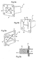
- FIG 3 a first variant of a second embodiment of the device of the figure 1 , in which the deformable element 8 is not constituted by a plate, but by folded edges 26 of the envelope 10.
- a cutout 28 of selected shape is formed between the edges 26 in order to size the absorption of the element 8.
- the casing 10 and the plate 6 are connected by weld seams 30.
- Reinforcements may advantageously be added to the deformable element 8 in order to increase its rigidity in order to better control its deformation and thus help maintain a constant level of effort.
- edges 26 are rectified at an angle ⁇ chosen relative to the plane of the fixing plate 6 to better control the deformation of the deformable element 8.
- zone 32 has cutouts 34 in the form of X whose branches are formed by its diagonals.
- zone 32 has an H-shaped cutout 36.
- the independent edges 38 and 40 can form a chosen angle with the plate 6, or be contained therein,
- the plate 6 may comprise alternatively a zone 42 of lesser thickness, in which the zone 32 is provided, in order to facilitate the programmed deformation.
- a punch 44 may be disposed at the end of the foam 12 facing the plate 6 and the zone 32 in the rest position, so as to ensure a good tearing of the deformable element 8, without the zone 32 has a reduced thickness or a particular cut.
Landscapes
- Engineering & Computer Science (AREA)
- Mechanical Engineering (AREA)
- Vibration Dampers (AREA)
- Body Structure For Vehicles (AREA)
- Fluid-Damping Devices (AREA)
Claims (10)
- Energieabsorbierende Vorrichtung für eine Stoßdämpferstange eines Kraftfahrzeugs, die eine Hülle (10), in der ein Energieabsorptionseigenschaften aufweisender Metallschaum (12) untergebracht ist, und eine Platte (6) zur Befestigung der Vorrichtung (2) an einem Teil des Kraftfahrzeugs enthält, dadurch gekennzeichnet, dass sie ein verformbares Element (8) mit einem Bereich (20) aufweist, der so konfiguriert ist, dass zur gleichen Zeit, in der der Metallschaum (12) sich verdichtet, der Bereich (20) des verformbaren Elements (8) sich verformt, indem er damit beginnt, sich zu öffnen, um einen progressiven Austritt des Metallschaums (12) durch das verformbare Element (8) hindurch zu ermöglichen.
- Vorrichtung nach Anspruch 1, dadurch gekennzeichnet, dass die Befestigungsplatte (6) eine Aushöhlung (16) mit ausgewählten Abmessungen gegenüber der Hülle (10) hat.
- Vorrichtung nach Anspruch 2, dadurch gekennzeichnet, dass das verformbare Element (8) eine Platte (18) ist, die mit der Befestigungsplatte (6) verbunden werden kann.
- Vorrichtung nach Anspruch 3, dadurch gekennzeichnet, dass das verformbare Element (8) einen Ausschnitt (22) ausgewählter Form gegenüber der Aushöhlung (16) der Befestigungsplatte (6) hat.
- Vorrichtung nach Anspruch 2, dadurch gekennzeichnet, dass das verformbare Element (8) durch umgebogene Ränder (26) der Hülle (10) hergestellt wird.
- Vorrichtung nach Anspruch 5, dadurch gekennzeichnet, dass das verformbare Element (8) einen Ausschnitt (28) ausgewählter Form hat.
- Vorrichtung nach Anspruch 1, dadurch gekennzeichnet, dass das verformbare Element (8) durch einen Bereich (42) der Befestigungsplatte (6) hergestellt wird, der eine verringerte Dicke hat.
- Vorrichtung nach Anspruch 1 oder 7, dadurch gekennzeichnet, dass das verformbare Element (8) durch einen Bereich (32) der Befestigungsplatte hergestellt wird, der einen Ausschnitt (36, 38) ausgewählter Form aufweist.
- Vorrichtung nach einem der vorhergehenden Ansprüche, dadurch gekennzeichnet, dass das verformbare Element (8) Verstärkungen hat, um seine Steifheit zu erhöhen.
- Vorrichtung nach einem der vorhergehenden Ansprüche, dadurch gekennzeichnet, dass sie aus metallischen Werkstoffen hergestellt ist, insbesondere aus Aluminiumlegierung oder aus Stahl.
Priority Applications (1)
| Application Number | Priority Date | Filing Date | Title |
|---|---|---|---|
| PL07116222T PL1902907T3 (pl) | 2006-09-20 | 2007-09-12 | Urządzenie pochłaniające energię dla belki zderzaka pojazdu samochodowego |
Applications Claiming Priority (1)
| Application Number | Priority Date | Filing Date | Title |
|---|---|---|---|
| FR0608241A FR2905925B1 (fr) | 2006-09-20 | 2006-09-20 | Dispositif d'absorption d'energie pour poutre pare-chocs de vehicule automobile. |
Publications (2)
| Publication Number | Publication Date |
|---|---|
| EP1902907A1 EP1902907A1 (de) | 2008-03-26 |
| EP1902907B1 true EP1902907B1 (de) | 2010-12-15 |
Family
ID=37697971
Family Applications (1)
| Application Number | Title | Priority Date | Filing Date |
|---|---|---|---|
| EP07116222A Not-in-force EP1902907B1 (de) | 2006-09-20 | 2007-09-12 | Energieabsorbierende Vorrichtung für eine Stossfängerstange eines Kraftfahrzeugs |
Country Status (5)
| Country | Link |
|---|---|
| EP (1) | EP1902907B1 (de) |
| AT (1) | ATE491603T1 (de) |
| DE (1) | DE602007011172D1 (de) |
| FR (1) | FR2905925B1 (de) |
| PL (1) | PL1902907T3 (de) |
Families Citing this family (3)
| Publication number | Priority date | Publication date | Assignee | Title |
|---|---|---|---|---|
| CN101811518B (zh) * | 2010-03-12 | 2011-08-10 | 重庆长安汽车股份有限公司 | 一种带加强吸能结构的汽车发动机舱边梁前段 |
| GB2510686A (en) * | 2013-12-11 | 2014-08-13 | Daimler Ag | An energy absorption device for a vehicle |
| CN111469789B (zh) * | 2020-04-30 | 2023-06-23 | 中国飞机强度研究所 | 一种组合式碰撞吸能结构及其应用方法 |
Family Cites Families (5)
| Publication number | Priority date | Publication date | Assignee | Title |
|---|---|---|---|---|
| US2997325A (en) * | 1959-09-15 | 1961-08-22 | Gerald H Peterson | Kinetic energy absorber |
| DE3836724A1 (de) * | 1988-10-28 | 1990-05-03 | Daimler Benz Ag | Pralldaempfer |
| FR2842152B1 (fr) * | 2002-07-15 | 2005-02-11 | Peugeot Citroen Automobiles Sa | Armature de pare-chocs avec elements absorbeur de chocs perfectionne |
| FR2876645B1 (fr) * | 2004-10-20 | 2008-04-25 | Valeo Thermique Moteur Sas | Dispositif absorbeur d'energie pour poutre pare-chocs de vehicule automobile |
| FR2887210B1 (fr) * | 2005-06-20 | 2007-08-24 | Valeo Systemes Thermiques | Dispositif absorbeur d'energie pour poutre pare-chocs de vehicule automobile |
-
2006
- 2006-09-20 FR FR0608241A patent/FR2905925B1/fr not_active Expired - Fee Related
-
2007
- 2007-09-12 DE DE602007011172T patent/DE602007011172D1/de active Active
- 2007-09-12 PL PL07116222T patent/PL1902907T3/pl unknown
- 2007-09-12 EP EP07116222A patent/EP1902907B1/de not_active Not-in-force
- 2007-09-12 AT AT07116222T patent/ATE491603T1/de not_active IP Right Cessation
Also Published As
| Publication number | Publication date |
|---|---|
| PL1902907T3 (pl) | 2011-07-29 |
| DE602007011172D1 (de) | 2011-01-27 |
| FR2905925B1 (fr) | 2009-04-03 |
| ATE491603T1 (de) | 2011-01-15 |
| EP1902907A1 (de) | 2008-03-26 |
| FR2905925A1 (fr) | 2008-03-21 |
Similar Documents
| Publication | Publication Date | Title |
|---|---|---|
| EP1893469B1 (de) | Geführter unterbereich der front eines automobils | |
| EP1902907B1 (de) | Energieabsorbierende Vorrichtung für eine Stossfängerstange eines Kraftfahrzeugs | |
| FR2842152A1 (fr) | Armature de pare-chocs avec elements absorbeur de chocs perfectionne | |
| FR2837762A1 (fr) | Poutre pare-chocs avec absorbeur d'energie pour vehicule automobile | |
| FR2809072A1 (fr) | Ensemble de structure de caisse comportant des longerons munis de zones d'amorce de pliage | |
| EP1972527B1 (de) | Verstärkte Motorschutzverkleidung für Fahrzeug | |
| EP1719670A1 (de) | Sicherheitseinrichtung für ein Fahrzeug mit einem elastisch verformbaren Element | |
| FR2741413A1 (fr) | Absorbeur de chocs pour vehicule automobile | |
| FR2887210A1 (fr) | Dispositif absorbeur d'energie pour poutre pare-chocs de vehicule automobile | |
| EP4351953A1 (de) | Stossdämpferelement für ein kraftfahrzeug | |
| EP1608536B1 (de) | Vorrichtung zur abstützung eines karosserieteiles eines kraftfahrzeuges | |
| WO2004060724A1 (fr) | Boitier absorbeur d'energie pour poutre pare-chocs de vehicule automobile | |
| FR2911824A1 (fr) | Ensemble d'absorption de chocs pour projecteur de vehicule automobile | |
| EP2132062B1 (de) | Baugruppe zur anbringung eines sicherheitsbeutelmoduls an einer mechanisch resistenten struktur eines armaturenbretts | |
| WO2018172641A1 (fr) | Dispositif de coussin de sécurité gonflable pour élément d'habillage intérieur de véhicule automobile. | |
| WO2006042999A1 (fr) | Capot de vehicule automobile avec doublure renforcee | |
| EP1930230A1 (de) | Fahrzeug mit Kühlerkassette, die mit mindestens einem Element zur Absorption eines Frontalzusammenstoßes ausgestattet ist | |
| EP3448701A1 (de) | Fahrzeugtür mit verstärker und fahrzeug mit solch einer tür | |
| WO2022243615A1 (fr) | Système de reprise d'effort sur une partie basse arrière d'un véhicule automobile | |
| EP2497690B1 (de) | Energieabsorber, Vorrichtung zur Energieabsorption, die einen solchen Absorber umfasst, und mit einer solchen Vorrichtung ausgestattetes Kraftfahrzeug | |
| FR3123275A1 (fr) | Ensemble polyvalent pour véhicule automobile comprenant une poutre de pare-chocs | |
| EP1874592A2 (de) | Frontstruktur für ein kraftfahrzeug | |
| EP3661814A1 (de) | Stossdämpferanordnung für kraftfahrzeug | |
| FR2855437A1 (fr) | Procede de fabrication d'un boitier absorbeur d'energie pour poutre pare-chocs de vehicule automobile | |
| FR3070147A1 (fr) | Dispositif de fixation d’un equipement sur un chassis de vehicule automobile ayant une cinematique de choc en rotation |
Legal Events
| Date | Code | Title | Description |
|---|---|---|---|
| PUAI | Public reference made under article 153(3) epc to a published international application that has entered the european phase |
Free format text: ORIGINAL CODE: 0009012 |
|
| AK | Designated contracting states |
Kind code of ref document: A1 Designated state(s): AT BE BG CH CY CZ DE DK EE ES FI FR GB GR HU IE IS IT LI LT LU LV MC MT NL PL PT RO SE SI SK TR |
|
| AX | Request for extension of the european patent |
Extension state: AL BA HR MK YU |
|
| 17P | Request for examination filed |
Effective date: 20080722 |
|
| 17Q | First examination report despatched |
Effective date: 20080902 |
|
| AKX | Designation fees paid |
Designated state(s): AT BE BG CH CY CZ DE DK EE ES FI FR GB GR HU IE IS IT LI LT LU LV MC MT NL PL PT RO SE SI SK TR |
|
| GRAP | Despatch of communication of intention to grant a patent |
Free format text: ORIGINAL CODE: EPIDOSNIGR1 |
|
| GRAS | Grant fee paid |
Free format text: ORIGINAL CODE: EPIDOSNIGR3 |
|
| GRAA | (expected) grant |
Free format text: ORIGINAL CODE: 0009210 |
|
| AK | Designated contracting states |
Kind code of ref document: B1 Designated state(s): AT BE BG CH CY CZ DE DK EE ES FI FR GB GR HU IE IS IT LI LT LU LV MC MT NL PL PT RO SE SI SK TR |
|
| REG | Reference to a national code |
Ref country code: GB Ref legal event code: FG4D Free format text: NOT ENGLISH Ref country code: CH Ref legal event code: EP |
|
| REG | Reference to a national code |
Ref country code: IE Ref legal event code: FG4D |
|
| REF | Corresponds to: |
Ref document number: 602007011172 Country of ref document: DE Date of ref document: 20110127 Kind code of ref document: P |
|
| REG | Reference to a national code |
Ref country code: NL Ref legal event code: VDEP Effective date: 20101215 |
|
| PG25 | Lapsed in a contracting state [announced via postgrant information from national office to epo] |
Ref country code: LT Free format text: LAPSE BECAUSE OF FAILURE TO SUBMIT A TRANSLATION OF THE DESCRIPTION OR TO PAY THE FEE WITHIN THE PRESCRIBED TIME-LIMIT Effective date: 20101215 |
|
| LTIE | Lt: invalidation of european patent or patent extension |
Effective date: 20101215 |
|
| PG25 | Lapsed in a contracting state [announced via postgrant information from national office to epo] |
Ref country code: SI Free format text: LAPSE BECAUSE OF FAILURE TO SUBMIT A TRANSLATION OF THE DESCRIPTION OR TO PAY THE FEE WITHIN THE PRESCRIBED TIME-LIMIT Effective date: 20101215 Ref country code: CY Free format text: LAPSE BECAUSE OF FAILURE TO SUBMIT A TRANSLATION OF THE DESCRIPTION OR TO PAY THE FEE WITHIN THE PRESCRIBED TIME-LIMIT Effective date: 20101215 Ref country code: LV Free format text: LAPSE BECAUSE OF FAILURE TO SUBMIT A TRANSLATION OF THE DESCRIPTION OR TO PAY THE FEE WITHIN THE PRESCRIBED TIME-LIMIT Effective date: 20101215 Ref country code: NL Free format text: LAPSE BECAUSE OF FAILURE TO SUBMIT A TRANSLATION OF THE DESCRIPTION OR TO PAY THE FEE WITHIN THE PRESCRIBED TIME-LIMIT Effective date: 20101215 Ref country code: SE Free format text: LAPSE BECAUSE OF FAILURE TO SUBMIT A TRANSLATION OF THE DESCRIPTION OR TO PAY THE FEE WITHIN THE PRESCRIBED TIME-LIMIT Effective date: 20101215 Ref country code: BG Free format text: LAPSE BECAUSE OF FAILURE TO SUBMIT A TRANSLATION OF THE DESCRIPTION OR TO PAY THE FEE WITHIN THE PRESCRIBED TIME-LIMIT Effective date: 20110315 Ref country code: AT Free format text: LAPSE BECAUSE OF FAILURE TO SUBMIT A TRANSLATION OF THE DESCRIPTION OR TO PAY THE FEE WITHIN THE PRESCRIBED TIME-LIMIT Effective date: 20101215 Ref country code: FI Free format text: LAPSE BECAUSE OF FAILURE TO SUBMIT A TRANSLATION OF THE DESCRIPTION OR TO PAY THE FEE WITHIN THE PRESCRIBED TIME-LIMIT Effective date: 20101215 |
|
| REG | Reference to a national code |
Ref country code: IE Ref legal event code: FD4D Ref country code: SK Ref legal event code: T3 Ref document number: E 9245 Country of ref document: SK |
|
| PG25 | Lapsed in a contracting state [announced via postgrant information from national office to epo] |
Ref country code: EE Free format text: LAPSE BECAUSE OF FAILURE TO SUBMIT A TRANSLATION OF THE DESCRIPTION OR TO PAY THE FEE WITHIN THE PRESCRIBED TIME-LIMIT Effective date: 20101215 Ref country code: GR Free format text: LAPSE BECAUSE OF FAILURE TO SUBMIT A TRANSLATION OF THE DESCRIPTION OR TO PAY THE FEE WITHIN THE PRESCRIBED TIME-LIMIT Effective date: 20110316 Ref country code: PT Free format text: LAPSE BECAUSE OF FAILURE TO SUBMIT A TRANSLATION OF THE DESCRIPTION OR TO PAY THE FEE WITHIN THE PRESCRIBED TIME-LIMIT Effective date: 20110415 Ref country code: ES Free format text: LAPSE BECAUSE OF FAILURE TO SUBMIT A TRANSLATION OF THE DESCRIPTION OR TO PAY THE FEE WITHIN THE PRESCRIBED TIME-LIMIT Effective date: 20110326 Ref country code: CZ Free format text: LAPSE BECAUSE OF FAILURE TO SUBMIT A TRANSLATION OF THE DESCRIPTION OR TO PAY THE FEE WITHIN THE PRESCRIBED TIME-LIMIT Effective date: 20101215 Ref country code: IE Free format text: LAPSE BECAUSE OF FAILURE TO SUBMIT A TRANSLATION OF THE DESCRIPTION OR TO PAY THE FEE WITHIN THE PRESCRIBED TIME-LIMIT Effective date: 20101215 Ref country code: IS Free format text: LAPSE BECAUSE OF FAILURE TO SUBMIT A TRANSLATION OF THE DESCRIPTION OR TO PAY THE FEE WITHIN THE PRESCRIBED TIME-LIMIT Effective date: 20110415 |
|
| REG | Reference to a national code |
Ref country code: PL Ref legal event code: T3 |
|
| PG25 | Lapsed in a contracting state [announced via postgrant information from national office to epo] |
Ref country code: RO Free format text: LAPSE BECAUSE OF FAILURE TO SUBMIT A TRANSLATION OF THE DESCRIPTION OR TO PAY THE FEE WITHIN THE PRESCRIBED TIME-LIMIT Effective date: 20101215 |
|
| PLBE | No opposition filed within time limit |
Free format text: ORIGINAL CODE: 0009261 |
|
| STAA | Information on the status of an ep patent application or granted ep patent |
Free format text: STATUS: NO OPPOSITION FILED WITHIN TIME LIMIT |
|
| PG25 | Lapsed in a contracting state [announced via postgrant information from national office to epo] |
Ref country code: DK Free format text: LAPSE BECAUSE OF FAILURE TO SUBMIT A TRANSLATION OF THE DESCRIPTION OR TO PAY THE FEE WITHIN THE PRESCRIBED TIME-LIMIT Effective date: 20101215 |
|
| 26N | No opposition filed |
Effective date: 20110916 |
|
| REG | Reference to a national code |
Ref country code: DE Ref legal event code: R097 Ref document number: 602007011172 Country of ref document: DE Effective date: 20110916 |
|
| BERE | Be: lapsed |
Owner name: VALEO SYSTEMES THERMIQUES Effective date: 20110930 |
|
| PG25 | Lapsed in a contracting state [announced via postgrant information from national office to epo] |
Ref country code: MC Free format text: LAPSE BECAUSE OF NON-PAYMENT OF DUE FEES Effective date: 20110930 |
|
| REG | Reference to a national code |
Ref country code: CH Ref legal event code: PL |
|
| GBPC | Gb: european patent ceased through non-payment of renewal fee |
Effective date: 20110912 |
|
| PG25 | Lapsed in a contracting state [announced via postgrant information from national office to epo] |
Ref country code: BE Free format text: LAPSE BECAUSE OF NON-PAYMENT OF DUE FEES Effective date: 20110930 |
|
| PG25 | Lapsed in a contracting state [announced via postgrant information from national office to epo] |
Ref country code: LI Free format text: LAPSE BECAUSE OF NON-PAYMENT OF DUE FEES Effective date: 20110930 Ref country code: CH Free format text: LAPSE BECAUSE OF NON-PAYMENT OF DUE FEES Effective date: 20110930 |
|
| PG25 | Lapsed in a contracting state [announced via postgrant information from national office to epo] |
Ref country code: GB Free format text: LAPSE BECAUSE OF NON-PAYMENT OF DUE FEES Effective date: 20110912 |
|
| PG25 | Lapsed in a contracting state [announced via postgrant information from national office to epo] |
Ref country code: MT Free format text: LAPSE BECAUSE OF FAILURE TO SUBMIT A TRANSLATION OF THE DESCRIPTION OR TO PAY THE FEE WITHIN THE PRESCRIBED TIME-LIMIT Effective date: 20101215 |
|
| PG25 | Lapsed in a contracting state [announced via postgrant information from national office to epo] |
Ref country code: LU Free format text: LAPSE BECAUSE OF NON-PAYMENT OF DUE FEES Effective date: 20110912 |
|
| PG25 | Lapsed in a contracting state [announced via postgrant information from national office to epo] |
Ref country code: TR Free format text: LAPSE BECAUSE OF FAILURE TO SUBMIT A TRANSLATION OF THE DESCRIPTION OR TO PAY THE FEE WITHIN THE PRESCRIBED TIME-LIMIT Effective date: 20101215 |
|
| PG25 | Lapsed in a contracting state [announced via postgrant information from national office to epo] |
Ref country code: HU Free format text: LAPSE BECAUSE OF FAILURE TO SUBMIT A TRANSLATION OF THE DESCRIPTION OR TO PAY THE FEE WITHIN THE PRESCRIBED TIME-LIMIT Effective date: 20101215 |
|
| REG | Reference to a national code |
Ref country code: FR Ref legal event code: PLFP Year of fee payment: 10 |
|
| REG | Reference to a national code |
Ref country code: FR Ref legal event code: PLFP Year of fee payment: 11 |
|
| REG | Reference to a national code |
Ref country code: FR Ref legal event code: PLFP Year of fee payment: 12 |
|
| PGFP | Annual fee paid to national office [announced via postgrant information from national office to epo] |
Ref country code: DE Payment date: 20190913 Year of fee payment: 13 Ref country code: SK Payment date: 20190816 Year of fee payment: 13 Ref country code: FR Payment date: 20190930 Year of fee payment: 13 Ref country code: IT Payment date: 20190916 Year of fee payment: 13 |
|
| PGFP | Annual fee paid to national office [announced via postgrant information from national office to epo] |
Ref country code: PL Payment date: 20190819 Year of fee payment: 13 |
|
| REG | Reference to a national code |
Ref country code: DE Ref legal event code: R119 Ref document number: 602007011172 Country of ref document: DE |
|
| REG | Reference to a national code |
Ref country code: SK Ref legal event code: MM4A Ref document number: E 9245 Country of ref document: SK Effective date: 20200912 |
|
| PG25 | Lapsed in a contracting state [announced via postgrant information from national office to epo] |
Ref country code: FR Free format text: LAPSE BECAUSE OF NON-PAYMENT OF DUE FEES Effective date: 20200930 Ref country code: DE Free format text: LAPSE BECAUSE OF NON-PAYMENT OF DUE FEES Effective date: 20210401 Ref country code: SK Free format text: LAPSE BECAUSE OF NON-PAYMENT OF DUE FEES Effective date: 20200912 |
|
| PG25 | Lapsed in a contracting state [announced via postgrant information from national office to epo] |
Ref country code: IT Free format text: LAPSE BECAUSE OF NON-PAYMENT OF DUE FEES Effective date: 20200912 |
|
| PG25 | Lapsed in a contracting state [announced via postgrant information from national office to epo] |
Ref country code: PL Free format text: LAPSE BECAUSE OF NON-PAYMENT OF DUE FEES Effective date: 20200912 |