EP1902635A1 - A machine for manufacturing cigarette filters - Google Patents
A machine for manufacturing cigarette filters Download PDFInfo
- Publication number
- EP1902635A1 EP1902635A1 EP07116492A EP07116492A EP1902635A1 EP 1902635 A1 EP1902635 A1 EP 1902635A1 EP 07116492 A EP07116492 A EP 07116492A EP 07116492 A EP07116492 A EP 07116492A EP 1902635 A1 EP1902635 A1 EP 1902635A1
- Authority
- EP
- European Patent Office
- Prior art keywords
- upper portion
- machine
- guard door
- dividing baffle
- containing structure
- Prior art date
- Legal status (The legal status is an assumption and is not a legal conclusion. Google has not performed a legal analysis and makes no representation as to the accuracy of the status listed.)
- Granted
Links
Images


Classifications
-
- A—HUMAN NECESSITIES
- A24—TOBACCO; CIGARS; CIGARETTES; SIMULATED SMOKING DEVICES; SMOKERS' REQUISITES
- A24D—CIGARS; CIGARETTES; TOBACCO SMOKE FILTERS; MOUTHPIECES OF CIGARS OR CIGARETTES; MANUFACTURE OF TOBACCO SMOKE FILTERS OR MOUTHPIECES
- A24D3/00—Tobacco smoke filters, e.g. filter tips or filtering inserts; Filters specially adapted for simulated smoking devices; Mouthpieces of cigars or cigarettes
- A24D3/02—Manufacture of tobacco smoke filters
- A24D3/0204—Preliminary operations before the filter rod forming process, e.g. crimping, blooming
- A24D3/0212—Applying additives to filter materials
Definitions
- the present invention relates to a machine for manufacturing cigarette filters.
- machines utilized in the tobacco industry include cigarette filter makers that operate by forming continuous streams or webs of filter material, drawn initially from compact bales of fibrous tow held in magazines placed upstream of the production line.
- the tow is pulled from the bales and ordered into one or more webs, which then undergo a succession of chemical and mechanical steps and are fashioned ultimately into long continuous rods of filter material.
- the filter material drawn from the bales is directed through a stretching unit and a rolling unit by which the fibrous tow is elongated so as to enable the formation of the aforementioned continuous webs.
- blower unit Located downstream of the rolling unit is a blower unit that serves to spread and separate the strands making up the web in such a manner that a uniform and consistent distribution is obtained across the full width of the advancing material, and the density of the single webs thus rendered similarly constant.
- the continuous web is caused to pass through a chemical treatment unit, by which the filter material will be impregnated with substances designed to give it a required plasticity.
- blower unit and the chemical treatment unit are housed within a common structure, separated by a partition or baffle, and the continuous web is directed through a slot formed in the baffle, passing thus from the blower unit to the chemical treatment unit.
- the continuous web of material passes through a slot in the dividing baffle and consequently cannot be moved while occupying the two units without the risk of the material breaking.
- the object of the present invention is to provide a machine for manufacturing cigarette filters that will be unaffected by the drawbacks mentioned above.
- the object of the invention is to provide a cigarette filter maker in which the continuous web of filter material passing through the blower unit and the chemical treatment unit can be repositioned at least partially.
- a further object of the invention is to provide a cigarette filter maker in which the blower unit and the chemical treatment unit are easily inspected.
- numeral 1 denotes a machine for manufacturing cigarette filters, in accordance with the present invention.
- the machine 1 comprises a containing structure 2, or enclosure, in which to house a blower station or unit 3 located in the right hand portion, as seen in figure 1, and a chemical treatment station or unit 4 located on the left as seen in figure 1.
- blower unit 3 serves to invest at last one continuous web 100 of filter material with a flow of air in order to augment its volume.
- the machine 1 is able to process two continuous webs 100 of filter material advancing parallel one with another.
- the blower unit 13 comprises an infeed station 3a, indicated in figure 1, through which to direct two fibrous filter tows drawn from respective magazines containing bales of this same material.
- Each tow is pulled forward and into the blower unit 3 by the action of a set of rollers 5, as illustrated schematically in figure 1.
- the function of the chemical treatment unit 4, placed inside the containing structure 2 downstream of the blower unit 3, and more exactly downstream of the rollers 5, is to impregnate the webs 100 with chemical additive substances of familiar type, such as triacetin, serving to give the filter material a certain plasticity.
- rollers 6 are located internally of the chemical treatment unit 4, indicated schematically in figure 1 and serving to advance the continuous webs 100 toward an outfeed station (not indicated) of the machine 1.
- the impregnating step is effected by a suitable additivation device 7, illustrated schematically in figure 1 that must be isolated appropriately from the blower unit 3.
- the mechanical steps performed by the blower unit 3 have the effect of throwing up a cloud of dust from the webs 100, which must be prevented at all costs from entering the chemical treatment unit 4, and in particular from reaching the additivation device 7.
- the machine 1 comprises an active dividing baffle 8 placed between the blower unit 3 and the chemical treatment unit 4, and more exactly between the rollers 5 and the chemical treatment unit 4.
- the dividing baffle 8 is fashioned with slots 9 equal in number to the number of the webs 100 of tow processed at one time by the machine 1.
- the number of webs 100 processed at one time is two, so that the slots 9 likewise are two in number.
- the two slots 9 serve to allow the passage of the continuous webs 100 from the blower unit 3 to the chemical treatment unit 4, and will be shaped substantially to match the cross sectional outline of the selfsame webs 100, so that only the actual fibres are admitted.
- the dividing baffle 8 is housed completely within the containing structure 2.
- the containing structure 2 comprises a base frame 10 from which two flank walls 11 and 12 and a rear wall (not illustrated) extend upwards.
- the structure 2 further comprises a guard door 13 extending between the flank walls 11 and 12, on the opposite side to the rear wall.
- the guard door 13 is capable of movement between a closed position, in which the containing structure 2 is sealed and access to the blower unit 3 and the chemical treatment unit 4 disallowed, and an open position (figures 1 and 4) in which the two units 3 and 4 are directly accessible.
- the guard door 13 is composed of an upper portion 14 and a lower portion 15 that can be drawn apart and brought together in such a manner as to establish the open position and the closed position, respectively.
- the upper portion 14 of the guard door 13 is embodied with areas 16 made of transparent material through which the two units 3 and 4 remain exposed to view, even when the guard door 13 is in the closed position.
- the upper portion 14 of the guard door 13 is also anchored pivotably to the containing structure 2 about a first axis "P" of rotation, in such a way that the selfsame portion 14 can swing, relative to the containing structure 2, between the open and closed positions.
- the first axis "P" of rotation is disposed substantially horizontal and perpendicular to the dividing baffle 8, and intercepts the two flank walls 11 and 12 of the containing structure 2 substantially at corresponding end portions of the selfsame walls.
- Numeral 17 denotes first drive means 17 indicated schematically in figures 2, 3 and 4, by which the upper portion 14 of the guard door 13 is caused to pivot about the first axis "P" of rotation.
- the upper portion 14 is also associated hingedly with a panel 14a serving to join the selfsame upper portion 14 to the uppermost part of the containing structure 2.
- the panel 14a rotates in sympathy with the upper portion 14 of the guard door 13 during its opening and closing movements.
- the lower portion 15 of the guard door 13 is capable of movement along a track or runner 18, and set in motion indirectly by second drive means 19.
- These second drive means 19 are connected to a coupler 20, via a mechanical linkage 21, which is raised and lowered parallel to the track 18.
- the coupler 20 is secured to the lower portion 15 of the guard door 13, so that motion can be induced in the selfsame lower portion.
- the linkage 21 and the lower portion 15 are coupled in contrary motion.
- the two elements are connected one to another by a cable 22 looped around two return pulleys (not numbered in the drawings) in such a way that when the linkage 21 descends, the lower portion 15 ascends, and when the linkage 21 ascends, the lower portion 15 descends.
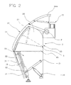
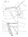
- the dividing baffle 8 is capable of motion between an operating position in which the two units 3 and 4 are partitioned one from another, as illustrated in figure 2, and a plurality of non-operating positions in which the two units 3 and 4 communicate one with another, as illustrated in figures 3 and 4.
- the dividing baffle 8 comprises an upper portion 23 and a lower portion 24.
- the upper portion 23 is capable of movement away from the lower portion 24, in such a way that the continuous webs 100 can be freed from the relative slots 9.
- the slots 9 are formed in the lower portion 24, directly facing the upper portion.
- the dividing baffle 8 presents a flap 9a (indicated in figure 1) hinged to the lower portion 24 and serving to hold the webs 100 in place, even when the baffle 8 is in a non-operating position.
- the flap 9a which might equally well not be included, can be opened easily and conveniently to gain access to the webs 100, and only when the upper portion 23 of the baffle is distanced from the lower portion 24.
- the dividing baffle 8 is set in motion between the operating position and the non-operating positions synchronously with the opening and closing movements of the guard door 13.
- the upper portion 23 of the baffle 8 is anchored permanently to the guard door 13, and in particular to the upper portion 14 of the door, by way of a mechanical linkage.
- the upper portion 23 of the dividing baffle 8 comprises a first element 25 and a second element 26, both of which substantially plate-like in appearance.
- the first element 25 is designed to make contact with the lower portion 24 of the dividing baffle 8 when the baffle occupies the operating position.
- first element 25 is anchored pivotably to the containing structure 2 by way of a second axis "S" of rotation lying parallel to and distanced from the first axis "P" of rotation.
- the second axis "S" is located at a level lower than that of the first axis "P".
- the first plate element 25 is linked mechanically to the guard door 13 by way of a connecting rod 27, as illustrated in figures 2 to 4, or in effect, by way of a stay rod hinged both to the guard door 13 and to the first element 25.
- the guard door 13 when caused to pivot on the relative axis by the first drive means 17, the guard door 13 will also induce angular motion in the first element 25 by way of the rod 27.
- guard door 13 and the first element 25 are pivotable about different centres of rotation, being aligned respectively on the first axis "P" and the second axis "S" of rotation, the angular movements described by the guard door 13 and by the first element 25 will be dissimilar one to another.
- the first element 25 describes an angle of rotation wider than that described by the guard door 13, as discernible in figures 3 and 4.
- the second element 26 presented by the upper portion 23 of the dividing baffle 8 is anchored directly and rigidly to the upper portion 14 of the guard door 13, so that the two parts move as one.
- the two elements 25 and 26 occupy respective mutually adjacent and parallel planes.
- the lower portion 24 of the dividing baffle 8 occupies a fixed position, anchored directly to the base frame 10 of the containing structure 2.
- the guard door 13 In operation, with the machine 1 running, the guard door 13 will be in the closed position, creating a sealed enclosure, with the dividing baffle 8 positioned to separate the blower unit 3 from the chemical treatment unit 4 while allowing the continuous webs 100 of filter tow to advance through the slots 9.
- the upward movement of the guard door also has the effect of raising the baffle 8, causing the units 3 and 4 to communicate one with another and rendering both accessible from outside.
- the first drive means 17 are activated to lower the upper portion of the guard door 13, closing the machine and engaging the webs 100 in the respective slots 9.
- the dividing baffle 8 is moved back into the operating position to separate the blower unit 3 and the chemical treatment unit 4.
Landscapes
- Preliminary Treatment Of Fibers (AREA)
- Manufacturing Of Cigar And Cigarette Tobacco (AREA)
Abstract
Description
- The present invention relates to a machine for manufacturing cigarette filters.
- Conventionally, machines utilized in the tobacco industry include cigarette filter makers that operate by forming continuous streams or webs of filter material, drawn initially from compact bales of fibrous tow held in magazines placed upstream of the production line.
- The tow is pulled from the bales and ordered into one or more webs, which then undergo a succession of chemical and mechanical steps and are fashioned ultimately into long continuous rods of filter material.
- In particular, the filter material drawn from the bales is directed through a stretching unit and a rolling unit by which the fibrous tow is elongated so as to enable the formation of the aforementioned continuous webs.
- Located downstream of the rolling unit is a blower unit that serves to spread and separate the strands making up the web in such a manner that a uniform and consistent distribution is obtained across the full width of the advancing material, and the density of the single webs thus rendered similarly constant.
- Thereafter, the continuous web is caused to pass through a chemical treatment unit, by which the filter material will be impregnated with substances designed to give it a required plasticity.
- Finally, the web undergoes a further mechanical operation whereby the strands are gathered and bunched to form a rope.
- In conventional machines, the blower unit and the chemical treatment unit are housed within a common structure, separated by a partition or baffle, and the continuous web is directed through a slot formed in the baffle, passing thus from the blower unit to the chemical treatment unit.
- The need to separate the two units by means of a dividing baffle is dictated by the fact that in the course of the mechanical blowing operation, the fibrous tow material sheds numerous lightweight particles, which if carried into the chemical treatment unit will be impregnated in the same way as the tow, collecting and forming fluff balls.
- These fluff balls drop onto the continuous web and are caught up in the strands, with the result that the web will include localized areas no longer presenting the correct plasticity.
- In practice however, the need to separate the two units physically with a dividing baffle conflicts with the need for the continuous web to remain accessible, so that it can be repositioned relative to the working parts of the two units, for example.
- In effect, as mentioned above, the continuous web of material passes through a slot in the dividing baffle and consequently cannot be moved while occupying the two units without the risk of the material breaking.
- For this same reason, moreover, it is all but impossible to remove the web temporarily from the components of the two units so that inspections and/or maintenance can be carried out on the units.
- Accordingly, the object of the present invention is to provide a machine for manufacturing cigarette filters that will be unaffected by the drawbacks mentioned above.
- In particular, the object of the invention is to provide a cigarette filter maker in which the continuous web of filter material passing through the blower unit and the chemical treatment unit can be repositioned at least partially.
- A further object of the invention is to provide a cigarette filter maker in which the blower unit and the chemical treatment unit are easily inspected.
- The stated objects are realized, according to the present invention, in a machine for manufacturing cigarette filters as characterized in any one or more of the appended claims.
- The invention will now be described in detail, by way of example, with the aid of the accompanying drawings, in which:
- figure 1 is a perspective view of a machine for manufacturing cigarette filters, in accordance with the present invention;
- figure 2 shows the machine of figure 1 in a side view, illustrating a first operating configuration with certain parts omitted better to reveal others;
- figure 3 shows the machine of figure 1 in a side view, illustrating a second operating configuration with certain parts omitted better to reveal others;
- figure 4 shows the machine of figure 1 in a side view, illustrating a third operating configuration with certain parts omitted better to reveal others.
- With reference to the accompanying drawings,
numeral 1 denotes a machine for manufacturing cigarette filters, in accordance with the present invention. - The
machine 1 comprises a containingstructure 2, or enclosure, in which to house a blower station orunit 3 located in the right hand portion, as seen in figure 1, and a chemical treatment station or unit 4 located on the left as seen in figure 1. - In particular, the
blower unit 3 serves to invest at last onecontinuous web 100 of filter material with a flow of air in order to augment its volume. - In the example of the accompanying drawings, which show a preferred embodiment of the invention, the
machine 1 is able to process twocontinuous webs 100 of filter material advancing parallel one with another. - In particular, the
blower unit 13 comprises aninfeed station 3a, indicated in figure 1, through which to direct two fibrous filter tows drawn from respective magazines containing bales of this same material. - Each tow is pulled forward and into the
blower unit 3 by the action of a set ofrollers 5, as illustrated schematically in figure 1. - The
rollers 5 serve also to stretch out the tows, in such a way that the aforementionedcontinuous webs 100 will appear substantially flat. - The function of the chemical treatment unit 4, placed inside the containing
structure 2 downstream of theblower unit 3, and more exactly downstream of therollers 5, is to impregnate thewebs 100 with chemical additive substances of familiar type, such as triacetin, serving to give the filter material a certain plasticity. -
Further rollers 6 are located internally of the chemical treatment unit 4, indicated schematically in figure 1 and serving to advance thecontinuous webs 100 toward an outfeed station (not indicated) of themachine 1. - The impregnating step is effected by a
suitable additivation device 7, illustrated schematically in figure 1 that must be isolated appropriately from theblower unit 3. - More specifically, the mechanical steps performed by the
blower unit 3 have the effect of throwing up a cloud of dust from thewebs 100, which must be prevented at all costs from entering the chemical treatment unit 4, and in particular from reaching theadditivation device 7. - Accordingly, the
machine 1 comprises an active dividingbaffle 8 placed between theblower unit 3 and the chemical treatment unit 4, and more exactly between therollers 5 and the chemical treatment unit 4. - The dividing
baffle 8 is fashioned with slots 9 equal in number to the number of thewebs 100 of tow processed at one time by themachine 1. - In the example of the drawings, which illustrate a preferred embodiment of the invention, the number of
webs 100 processed at one time is two, so that the slots 9 likewise are two in number. - The two slots 9 serve to allow the passage of the
continuous webs 100 from theblower unit 3 to the chemical treatment unit 4, and will be shaped substantially to match the cross sectional outline of theselfsame webs 100, so that only the actual fibres are admitted. - The dividing
baffle 8 is housed completely within the containingstructure 2. - With reference again to figure 1, the containing
structure 2 comprises abase frame 10 from which twoflank walls - The
structure 2 further comprises aguard door 13 extending between theflank walls guard door 13 is capable of movement between a closed position, in which the containingstructure 2 is sealed and access to theblower unit 3 and the chemical treatment unit 4 disallowed, and an open position (figures 1 and 4) in which the twounits 3 and 4 are directly accessible. - More exactly, the
guard door 13 is composed of anupper portion 14 and alower portion 15 that can be drawn apart and brought together in such a manner as to establish the open position and the closed position, respectively. - The
upper portion 14 of theguard door 13 is embodied withareas 16 made of transparent material through which the twounits 3 and 4 remain exposed to view, even when theguard door 13 is in the closed position. - The
upper portion 14 of theguard door 13 is also anchored pivotably to the containingstructure 2 about a first axis "P" of rotation, in such a way that theselfsame portion 14 can swing, relative to the containingstructure 2, between the open and closed positions. - In particular, the first axis "P" of rotation is disposed substantially horizontal and perpendicular to the dividing
baffle 8, and intercepts the twoflank walls structure 2 substantially at corresponding end portions of the selfsame walls. - Numeral 17 denotes first drive means 17 indicated schematically in figures 2, 3 and 4, by which the
upper portion 14 of theguard door 13 is caused to pivot about the first axis "P" of rotation. - The
upper portion 14 is also associated hingedly with apanel 14a serving to join the selfsameupper portion 14 to the uppermost part of the containingstructure 2. Thepanel 14a rotates in sympathy with theupper portion 14 of theguard door 13 during its opening and closing movements. - The
lower portion 15 of theguard door 13 is capable of movement along a track orrunner 18, and set in motion indirectly by second drive means 19. - These second drive means 19 are connected to a
coupler 20, via amechanical linkage 21, which is raised and lowered parallel to thetrack 18. - The
coupler 20 is secured to thelower portion 15 of theguard door 13, so that motion can be induced in the selfsame lower portion. - In the preferred embodiment of figures 2 to 4, the
linkage 21 and thelower portion 15 are coupled in contrary motion. The two elements are connected one to another by acable 22 looped around two return pulleys (not numbered in the drawings) in such a way that when thelinkage 21 descends, thelower portion 15 ascends, and when thelinkage 21 ascends, thelower portion 15 descends. - To advantage, the dividing
baffle 8 is capable of motion between an operating position in which the twounits 3 and 4 are partitioned one from another, as illustrated in figure 2, and a plurality of non-operating positions in which the twounits 3 and 4 communicate one with another, as illustrated in figures 3 and 4. - In particular, the dividing
baffle 8 comprises anupper portion 23 and alower portion 24. Theupper portion 23 is capable of movement away from thelower portion 24, in such a way that thecontinuous webs 100 can be freed from the relative slots 9. - To this end, the slots 9 are formed in the
lower portion 24, directly facing the upper portion. - In the preferred solution illustrated, moreover, the dividing
baffle 8 presents aflap 9a (indicated in figure 1) hinged to thelower portion 24 and serving to hold thewebs 100 in place, even when thebaffle 8 is in a non-operating position. - The
flap 9a, which might equally well not be included, can be opened easily and conveniently to gain access to thewebs 100, and only when theupper portion 23 of the baffle is distanced from thelower portion 24. - Accordingly, and to reiterate, when the
upper portion 23 of thebaffle 8 is moved away from thelower portion 24, thecontinuous webs 100 of tow can be handled and repositioned internally of themachine 1. - To advantage, the dividing
baffle 8 is set in motion between the operating position and the non-operating positions synchronously with the opening and closing movements of theguard door 13. - More exactly, when the
guard door 13 is in the closed position, the dividingbaffle 8 occupies the operating position (see figure 2), whereas with theguard door 13 in the open position, the dividingbaffle 8 will assume a non-operating position (see figures 1, 3 and 4). - For this purpose, in the example illustrated, the
upper portion 23 of thebaffle 8 is anchored permanently to theguard door 13, and in particular to theupper portion 14 of the door, by way of a mechanical linkage. - In detail, the
upper portion 23 of thedividing baffle 8 comprises afirst element 25 and asecond element 26, both of which substantially plate-like in appearance. - The
first element 25 is designed to make contact with thelower portion 24 of the dividingbaffle 8 when the baffle occupies the operating position. - In addition, the
first element 25 is anchored pivotably to the containingstructure 2 by way of a second axis "S" of rotation lying parallel to and distanced from the first axis "P" of rotation. - More exactly, the second axis "S" is located at a level lower than that of the first axis "P".
- The
first plate element 25 is linked mechanically to theguard door 13 by way of a connectingrod 27, as illustrated in figures 2 to 4, or in effect, by way of a stay rod hinged both to theguard door 13 and to thefirst element 25. - Thus, when caused to pivot on the relative axis by the first drive means 17, the
guard door 13 will also induce angular motion in thefirst element 25 by way of therod 27. - Moreover, since the
guard door 13 and thefirst element 25 are pivotable about different centres of rotation, being aligned respectively on the first axis "P" and the second axis "S" of rotation, the angular movements described by theguard door 13 and by thefirst element 25 will be dissimilar one to another. - In particular, the
first element 25 describes an angle of rotation wider than that described by theguard door 13, as discernible in figures 3 and 4. - The
second element 26 presented by theupper portion 23 of the dividingbaffle 8 is anchored directly and rigidly to theupper portion 14 of theguard door 13, so that the two parts move as one. - It will be seen that when motion is induced in the
upper portion 14 of theguard door 13, and therefore in theupper portion 23 of the dividingbaffle 8 also, thefirst element 25 and thesecond element 26 are caused to overlap in part, given that the rotation of the twoelements - To enable the partial overlapping configuration in question, the two
elements - The
lower portion 24 of the dividingbaffle 8 occupies a fixed position, anchored directly to thebase frame 10 of the containingstructure 2. - In operation, with the
machine 1 running, theguard door 13 will be in the closed position, creating a sealed enclosure, with the dividingbaffle 8 positioned to separate theblower unit 3 from the chemical treatment unit 4 while allowing thecontinuous webs 100 of filter tow to advance through the slots 9. - In the event of a malfunction occurring, or when the need simply arises for routine maintenance operations to be carried out on the
machine 1, the feed motion of thewebs 100 is shut off, and the first drive means 17 are activated to raise the upper portion of theguard door 13. - The upward movement of the guard door also has the effect of raising the
baffle 8, causing theunits 3 and 4 to communicate one with another and rendering both accessible from outside. - Lifting the
flap 9a (if installed), it will also be possible to release thecontinuous webs 100 from the slots 9 and displace them internally of themachine 1 as necessary. - With maintenance operations on the
machine 1 completed, the first drive means 17 are activated to lower the upper portion of theguard door 13, closing the machine and engaging thewebs 100 in the respective slots 9. - At the same time, the dividing
baffle 8 is moved back into the operating position to separate theblower unit 3 and the chemical treatment unit 4.
Claims (12)
- A machine for manufacturing cigarette filters, comprising:- at least one blower unit (3) acting on at least one continuous web (100) of filter material in such a way as to ensure, at least, that strands of the material are distributed uniformly and unbrokenly within the continuous web (100);- at least one chemical treatment unit (4) by which the continuous web (100) is impregnated with at least one chemical additive substance;- a dividing baffle (8), positioned between the blower unit (3) and the chemical treatment unit (4) and presenting at least one slot (9) through which the continuous web (100) is afforded a passage,characterized
in that the dividing baffle (8) is capable of movement between an operating position in which the units (3, 4) are separated by the selfsame baffle and the web (100) is engaged in the slot(9), and a plurality of non-operating positions in which the two units (3, 4) are in communication one with another and the web (100) is disengaged from the slot (9). - A machine as in claim 1, wherein the dividing baffle (8) comprises an upper portion (23) and a lower portion (24), and the at least one slot (9) is located in the lower portion (24) of the dividing baffle (8), positioned directly facing the upper portion (23).
- A machine as in claim 2, wherein the upper portion (23) of the dividing baffle (8) is capable of movement between a position of contact with the lower portion (24), coinciding with the operating position, and a plurality of positions distanced from the lower portion (24), coinciding with the plurality of non-operating positions.
- A machine as in preceding claims, comprising a containing structure (2) common to the blower unit (3) and the chemical treatment unit (4), wherein the dividing baffle (8) is housed in the containing structure (2).
- A machine as in claim 4, wherein the containing structure (2) comprises a guard door (13) capable of movement between a position in which the containing structure (2) is closed and access to the blower and chemical treatments unit (3, 4) denied, and a position in which the containing structure (2) is open and the two units (3, 4) are accessible.
- A machine as in claims 3 and 5, wherein the upper portion (23) of the dividing baffle (8) is anchored permanently to the guard door (13) by way of a mechanical linkage, in such a way that the dividing baffle (8) occupies the operating position when the guard door is in the closed position, and occupies one of the non-operating positions when the guard door (13) is in the open position.
- A machine as in claim 6, wherein the guard door (13) comprises an upper portion (14) and a lower portion (15) capable of movement toward and away from one another so as to define the open and closed positions, and the upper portion (23) of the dividing baffle (8) is anchored permanently by way of a mechanical linkage to the upper portion (14) of the guard door (13).
- A machine as in claim 7, wherein the upper portion (14) of the guard door (13) and the upper portion (23) of the dividing baffle (3) are anchored pivotably to the containing structure (2) about a first axis (P) and a second axis (S) extending substantially parallel one to another and perpendicular to a plane occupied by the dividing baffle (8), and rendered thus rotatable relative to the containing structure (2) between the open and closed positions and the operating and non-operating positions, respectively.
- A machine as in claims 6 to 8, wherein the upper portion (23) of the dividing baffle (8) comprises a first element (25) anchored mechanically to the guard door (13), also a second element (26) anchored directly to the upper portion (14) of the guard door (13) and rotatable as one with the guard door relative to the containing structure (2).
- A machine as in claim 8 and 9, wherein the first element (25) presented by the upper portion (23) of the dividing baffle (8) is anchored to the upper portion (14) of the guard door (13) by way of a connecting rod (27) and anchored rotatably to the containing structure (2) about the second axis (S).
- A machine as in claims 5 to 10, comprising first drive means (17) connected operationally with the guard door (13) and serving to move the selfsame door between the open and closed positions, wherein the upper portion (23) of the dividing baffle (8) is set in motion by the guard door (13).
- A machine as in claims 7 to 11, wherein the lower portion (15) of the guard door (13) is capable of movement along a track (18) and connected to second drive means (19) such as will induce its motion along the track (18).
Applications Claiming Priority (1)
| Application Number | Priority Date | Filing Date | Title |
|---|---|---|---|
| ITBO20060646 ITBO20060646A1 (en) | 2006-09-20 | 2006-09-20 | MACHINE FOR THE PRODUCTION OF CIGARETTE FILTERS |
Publications (2)
| Publication Number | Publication Date |
|---|---|
| EP1902635A1 true EP1902635A1 (en) | 2008-03-26 |
| EP1902635B1 EP1902635B1 (en) | 2011-11-16 |
Family
ID=38962630
Family Applications (1)
| Application Number | Title | Priority Date | Filing Date |
|---|---|---|---|
| EP20070116492 Active EP1902635B1 (en) | 2006-09-20 | 2007-09-14 | A machine for manufacturing cigarette filters |
Country Status (2)
| Country | Link |
|---|---|
| EP (1) | EP1902635B1 (en) |
| IT (1) | ITBO20060646A1 (en) |
Citations (8)
| Publication number | Priority date | Publication date | Assignee | Title |
|---|---|---|---|---|
| GB2067927A (en) | 1980-01-30 | 1981-08-05 | Baumgartner Papiers Sa | Plasticizer treatment of a rope of fibres |
| US5342657A (en) * | 1992-11-16 | 1994-08-30 | Philip Morris Incorporated | Apparatus and method for applying fluid to a moving continuous web |
| DE10123351A1 (en) * | 2001-05-14 | 2002-12-05 | Rhodia Acetow Gmbh | Cigarette-filter production machine and method involve preparation, drawing and humidity supply appliances, with suction pipe and steam injector |
| EP1314363A1 (en) * | 2000-08-31 | 2003-05-28 | Japan Tobacco Inc. | Filter manufacturing machine |
| EP1591026A1 (en) * | 2004-04-30 | 2005-11-02 | Hauni Maschinenbau AG | Scraping element and spraying device for filter tow |
| DE102004030171A1 (en) * | 2004-06-22 | 2006-02-09 | Hauni Maschinenbau Ag | Method for preparing strip material in the manufacture of cigarette filters has a fluid applied to the continuous feed strip in a closed chamber with extraction for surplus fluid and fumes |
| DE102006011599A1 (en) * | 2006-03-10 | 2007-09-13 | Hauni Maschinenbau Ag | Treatment method for processing a strip of filter tow material in the tobacco-processing industry feeds the filter strip along a conveyor belt |
| EP1834531A1 (en) * | 2006-03-10 | 2007-09-19 | Hauni Maschinenbau AG | Treatment of a filter material rod of the tobacco processing industry |
-
2006
- 2006-09-20 IT ITBO20060646 patent/ITBO20060646A1/en unknown
-
2007
- 2007-09-14 EP EP20070116492 patent/EP1902635B1/en active Active
Patent Citations (8)
| Publication number | Priority date | Publication date | Assignee | Title |
|---|---|---|---|---|
| GB2067927A (en) | 1980-01-30 | 1981-08-05 | Baumgartner Papiers Sa | Plasticizer treatment of a rope of fibres |
| US5342657A (en) * | 1992-11-16 | 1994-08-30 | Philip Morris Incorporated | Apparatus and method for applying fluid to a moving continuous web |
| EP1314363A1 (en) * | 2000-08-31 | 2003-05-28 | Japan Tobacco Inc. | Filter manufacturing machine |
| DE10123351A1 (en) * | 2001-05-14 | 2002-12-05 | Rhodia Acetow Gmbh | Cigarette-filter production machine and method involve preparation, drawing and humidity supply appliances, with suction pipe and steam injector |
| EP1591026A1 (en) * | 2004-04-30 | 2005-11-02 | Hauni Maschinenbau AG | Scraping element and spraying device for filter tow |
| DE102004030171A1 (en) * | 2004-06-22 | 2006-02-09 | Hauni Maschinenbau Ag | Method for preparing strip material in the manufacture of cigarette filters has a fluid applied to the continuous feed strip in a closed chamber with extraction for surplus fluid and fumes |
| DE102006011599A1 (en) * | 2006-03-10 | 2007-09-13 | Hauni Maschinenbau Ag | Treatment method for processing a strip of filter tow material in the tobacco-processing industry feeds the filter strip along a conveyor belt |
| EP1834531A1 (en) * | 2006-03-10 | 2007-09-19 | Hauni Maschinenbau AG | Treatment of a filter material rod of the tobacco processing industry |
Also Published As
| Publication number | Publication date |
|---|---|
| ITBO20060646A1 (en) | 2006-12-20 |
| EP1902635B1 (en) | 2011-11-16 |
Similar Documents
| Publication | Publication Date | Title |
|---|---|---|
| US5269124A (en) | Crop conditioner | |
| PT94519B (en) | MINERAL FIBER RECEPTION PROCESS AND DEVICE | |
| JPH06165664A (en) | Slicing device particularly for tobacco package | |
| EP1902635B1 (en) | A machine for manufacturing cigarette filters | |
| US3598680A (en) | Tandem air former | |
| JPH0382827A (en) | Device to supply massive fiber material to processing device | |
| RU2375935C2 (en) | Method and machine for production of filters for tobacco products | |
| JPH0847571A (en) | Amusement machine | |
| DE3832098C2 (en) | Device and method for producing a fiber cushion | |
| US3613692A (en) | Apparatus for building a continuous tobacco stream | |
| EP1082914B1 (en) | System for the reduction of the noise level for producing machines subjected to the action of an air flow in the tobacco industry | |
| US4956896A (en) | Method and apparatus for forming nonwoven fiber webs | |
| EP0145670B1 (en) | Device for forming loops of printed fabrics | |
| EP1902634A2 (en) | A machine for manufacturing cigarette filters | |
| US7509960B2 (en) | Automatic machine for processing tobacco articles | |
| DE202014103343U1 (en) | Treatment device, in particular drying device | |
| CN109159959A (en) | A kind of food production is packed for conveying equipment | |
| JP2010046061A (en) | Device for protecting machine in tobacco processing industry | |
| FR2564294A1 (en) | PROCESS FOR MANUFACTURING RECONSTITUTED TOBACCO | |
| CS208762B2 (en) | Loom | |
| JPS5913221B2 (en) | Disposal equipment for cigarette waste, etc. in pachinko machine rows | |
| US2002120A (en) | Method of and apparatus for conditioning cigar wrapper leaf tobacco | |
| CN216064162U (en) | A cigarette block processing device | |
| CN223862326U (en) | Cigarette packet outer packing detecting system | |
| CN222035743U (en) | Potato sorting device |
Legal Events
| Date | Code | Title | Description |
|---|---|---|---|
| PUAI | Public reference made under article 153(3) epc to a published international application that has entered the european phase |
Free format text: ORIGINAL CODE: 0009012 |
|
| AK | Designated contracting states |
Kind code of ref document: A1 Designated state(s): AT BE BG CH CY CZ DE DK EE ES FI FR GB GR HU IE IS IT LI LT LU LV MC MT NL PL PT RO SE SI SK TR |
|
| AX | Request for extension of the european patent |
Extension state: AL BA HR MK YU |
|
| 17P | Request for examination filed |
Effective date: 20080429 |
|
| AKX | Designation fees paid |
Designated state(s): CH DE GB LI TR |
|
| 17Q | First examination report despatched |
Effective date: 20100805 |
|
| GRAP | Despatch of communication of intention to grant a patent |
Free format text: ORIGINAL CODE: EPIDOSNIGR1 |
|
| GRAS | Grant fee paid |
Free format text: ORIGINAL CODE: EPIDOSNIGR3 |
|
| GRAA | (expected) grant |
Free format text: ORIGINAL CODE: 0009210 |
|
| AK | Designated contracting states |
Kind code of ref document: B1 Designated state(s): CH DE GB LI TR |
|
| REG | Reference to a national code |
Ref country code: GB Ref legal event code: FG4D |
|
| REG | Reference to a national code |
Ref country code: CH Ref legal event code: EP |
|
| REG | Reference to a national code |
Ref country code: DE Ref legal event code: R096 Ref document number: 602007018723 Country of ref document: DE Effective date: 20120119 |
|
| PLBE | No opposition filed within time limit |
Free format text: ORIGINAL CODE: 0009261 |
|
| STAA | Information on the status of an ep patent application or granted ep patent |
Free format text: STATUS: NO OPPOSITION FILED WITHIN TIME LIMIT |
|
| 26N | No opposition filed |
Effective date: 20120817 |
|
| REG | Reference to a national code |
Ref country code: DE Ref legal event code: R097 Ref document number: 602007018723 Country of ref document: DE Effective date: 20120817 |
|
| REG | Reference to a national code |
Ref country code: CH Ref legal event code: PL |
|
| PG25 | Lapsed in a contracting state [announced via postgrant information from national office to epo] |
Ref country code: CH Free format text: LAPSE BECAUSE OF NON-PAYMENT OF DUE FEES Effective date: 20120930 Ref country code: LI Free format text: LAPSE BECAUSE OF NON-PAYMENT OF DUE FEES Effective date: 20120930 |
|
| PG25 | Lapsed in a contracting state [announced via postgrant information from national office to epo] |
Ref country code: TR Free format text: LAPSE BECAUSE OF FAILURE TO SUBMIT A TRANSLATION OF THE DESCRIPTION OR TO PAY THE FEE WITHIN THE PRESCRIBED TIME-LIMIT Effective date: 20111116 |
|
| PGFP | Annual fee paid to national office [announced via postgrant information from national office to epo] |
Ref country code: GB Payment date: 20140929 Year of fee payment: 8 |
|
| GBPC | Gb: european patent ceased through non-payment of renewal fee |
Effective date: 20150914 |
|
| PG25 | Lapsed in a contracting state [announced via postgrant information from national office to epo] |
Ref country code: GB Free format text: LAPSE BECAUSE OF NON-PAYMENT OF DUE FEES Effective date: 20150914 |
|
| PGFP | Annual fee paid to national office [announced via postgrant information from national office to epo] |
Ref country code: DE Payment date: 20250929 Year of fee payment: 19 |