EP1901290A1 - Optical recording medium and method of manufacturing the same - Google Patents
Optical recording medium and method of manufacturing the same Download PDFInfo
- Publication number
- EP1901290A1 EP1901290A1 EP07011039A EP07011039A EP1901290A1 EP 1901290 A1 EP1901290 A1 EP 1901290A1 EP 07011039 A EP07011039 A EP 07011039A EP 07011039 A EP07011039 A EP 07011039A EP 1901290 A1 EP1901290 A1 EP 1901290A1
- Authority
- EP
- European Patent Office
- Prior art keywords
- substrate
- recording
- recording medium
- optical recording
- layer
- Prior art date
- Legal status (The legal status is an assumption and is not a legal conclusion. Google has not performed a legal analysis and makes no representation as to the accuracy of the status listed.)
- Withdrawn
Links
Images




Classifications
-
- G—PHYSICS
- G11—INFORMATION STORAGE
- G11B—INFORMATION STORAGE BASED ON RELATIVE MOVEMENT BETWEEN RECORD CARRIER AND TRANSDUCER
- G11B7/00—Recording or reproducing by optical means, e.g. recording using a thermal beam of optical radiation by modifying optical properties or the physical structure, reproducing using an optical beam at lower power by sensing optical properties; Record carriers therefor
- G11B7/004—Recording, reproducing or erasing methods; Read, write or erase circuits therefor
- G11B7/0065—Recording, reproducing or erasing by using optical interference patterns, e.g. holograms
-
- G—PHYSICS
- G03—PHOTOGRAPHY; CINEMATOGRAPHY; ANALOGOUS TECHNIQUES USING WAVES OTHER THAN OPTICAL WAVES; ELECTROGRAPHY; HOLOGRAPHY
- G03H—HOLOGRAPHIC PROCESSES OR APPARATUS
- G03H1/00—Holographic processes or apparatus using light, infrared or ultraviolet waves for obtaining holograms or for obtaining an image from them; Details peculiar thereto
- G03H1/02—Details of features involved during the holographic process; Replication of holograms without interference recording
-
- G—PHYSICS
- G11—INFORMATION STORAGE
- G11B—INFORMATION STORAGE BASED ON RELATIVE MOVEMENT BETWEEN RECORD CARRIER AND TRANSDUCER
- G11B7/00—Recording or reproducing by optical means, e.g. recording using a thermal beam of optical radiation by modifying optical properties or the physical structure, reproducing using an optical beam at lower power by sensing optical properties; Record carriers therefor
- G11B7/007—Arrangement of the information on the record carrier, e.g. form of tracks, actual track shape, e.g. wobbled, or cross-section, e.g. v-shaped; Sequential information structures, e.g. sectoring or header formats within a track
- G11B7/00772—Arrangement of the information on the record carrier, e.g. form of tracks, actual track shape, e.g. wobbled, or cross-section, e.g. v-shaped; Sequential information structures, e.g. sectoring or header formats within a track on record carriers storing information in the form of optical interference patterns, e.g. holograms
- G11B7/00781—Auxiliary information, e.g. index marks, address marks, pre-pits, gray codes
-
- G—PHYSICS
- G11—INFORMATION STORAGE
- G11B—INFORMATION STORAGE BASED ON RELATIVE MOVEMENT BETWEEN RECORD CARRIER AND TRANSDUCER
- G11B7/00—Recording or reproducing by optical means, e.g. recording using a thermal beam of optical radiation by modifying optical properties or the physical structure, reproducing using an optical beam at lower power by sensing optical properties; Record carriers therefor
- G11B7/24—Record carriers characterised by shape, structure or physical properties, or by the selection of the material
- G11B7/24018—Laminated discs
- G11B7/24021—Laminated discs provided with a special shape or structure for centering or eccentricity prevention, e.g. alignment
-
- G—PHYSICS
- G11—INFORMATION STORAGE
- G11B—INFORMATION STORAGE BASED ON RELATIVE MOVEMENT BETWEEN RECORD CARRIER AND TRANSDUCER
- G11B7/00—Recording or reproducing by optical means, e.g. recording using a thermal beam of optical radiation by modifying optical properties or the physical structure, reproducing using an optical beam at lower power by sensing optical properties; Record carriers therefor
- G11B7/24—Record carriers characterised by shape, structure or physical properties, or by the selection of the material
- G11B7/2403—Layers; Shape, structure or physical properties thereof
- G11B7/24035—Recording layers
- G11B7/24044—Recording layers for storing optical interference patterns, e.g. holograms; for storing data in three dimensions [3D], e.g. volume storage
-
- G—PHYSICS
- G03—PHOTOGRAPHY; CINEMATOGRAPHY; ANALOGOUS TECHNIQUES USING WAVES OTHER THAN OPTICAL WAVES; ELECTROGRAPHY; HOLOGRAPHY
- G03H—HOLOGRAPHIC PROCESSES OR APPARATUS
- G03H1/00—Holographic processes or apparatus using light, infrared or ultraviolet waves for obtaining holograms or for obtaining an image from them; Details peculiar thereto
- G03H1/04—Processes or apparatus for producing holograms
- G03H1/18—Particular processing of hologram record carriers, e.g. for obtaining blazed holograms
- G03H2001/186—Swelling or shrinking the holographic record or compensation thereof, e.g. for controlling the reconstructed wavelength
-
- G—PHYSICS
- G03—PHOTOGRAPHY; CINEMATOGRAPHY; ANALOGOUS TECHNIQUES USING WAVES OTHER THAN OPTICAL WAVES; ELECTROGRAPHY; HOLOGRAPHY
- G03H—HOLOGRAPHIC PROCESSES OR APPARATUS
- G03H2250/00—Laminate comprising a hologram layer
- G03H2250/37—Enclosing the photosensitive material
-
- G—PHYSICS
- G03—PHOTOGRAPHY; CINEMATOGRAPHY; ANALOGOUS TECHNIQUES USING WAVES OTHER THAN OPTICAL WAVES; ELECTROGRAPHY; HOLOGRAPHY
- G03H—HOLOGRAPHIC PROCESSES OR APPARATUS
- G03H2260/00—Recording materials or recording processes
- G03H2260/12—Photopolymer
-
- G—PHYSICS
- G11—INFORMATION STORAGE
- G11B—INFORMATION STORAGE BASED ON RELATIVE MOVEMENT BETWEEN RECORD CARRIER AND TRANSDUCER
- G11B7/00—Recording or reproducing by optical means, e.g. recording using a thermal beam of optical radiation by modifying optical properties or the physical structure, reproducing using an optical beam at lower power by sensing optical properties; Record carriers therefor
- G11B7/24—Record carriers characterised by shape, structure or physical properties, or by the selection of the material
- G11B7/26—Apparatus or processes specially adapted for the manufacture of record carriers
- G11B7/263—Preparing and using a stamper, e.g. pressing or injection molding substrates
-
- Y—GENERAL TAGGING OF NEW TECHNOLOGICAL DEVELOPMENTS; GENERAL TAGGING OF CROSS-SECTIONAL TECHNOLOGIES SPANNING OVER SEVERAL SECTIONS OF THE IPC; TECHNICAL SUBJECTS COVERED BY FORMER USPC CROSS-REFERENCE ART COLLECTIONS [XRACs] AND DIGESTS
- Y10—TECHNICAL SUBJECTS COVERED BY FORMER USPC
- Y10T—TECHNICAL SUBJECTS COVERED BY FORMER US CLASSIFICATION
- Y10T428/00—Stock material or miscellaneous articles
- Y10T428/24—Structurally defined web or sheet [e.g., overall dimension, etc.]
- Y10T428/24479—Structurally defined web or sheet [e.g., overall dimension, etc.] including variation in thickness
- Y10T428/2457—Parallel ribs and/or grooves
Definitions
- the present invention specifically relates to an optical recording medium in which information can be recorded by hologram and information can be reproduced by irradiating beam, and a method of manufacturing the same.
- a holographic data storage is a memory for recording information in a recording medium using holographic technology by overlapping signal beam having image information and reference beam in the interior of the recording medium and writing interference patterns generated at this time in the recording medium.
- the recorded information is read by irradiating the reference beam to the recording medium and obtaining the image information from diffraction caused by the interference patterns.
- U.S. Patent No.5698344 discloses a holographic data storage and a holographic recording/reproducing medium for recording and reproducing information with respect thereto.
- the interference patterns are three-dimensionally written using the thickness of the recording medium, selectivity of the wavelength and the angle of beam is high, and hence multiplexing is enabled and high recording capacity is achieved. Since the image information can be read by one shot, it has an advantage such that the transfer rate of reproduced signals is high.
- the image information to be recorded is generally encoded digital information.
- the recorded image information is reproduced and decoded to take out as information.
- the most-used photopolymer as a medium of the holographic data storage achieves recording by generating a density distribution, so that the volume of the recording layer is reduced by recording.
- the method of reproduction must be thought out.
- reproduction may be achieved by varying the angle of a disk with respect to reproducing beam or varying the position of a detector for the reproducing beam in the case of off-axis holographic recording, and by varying conversion conditions (decoding condition) of the intensity of the reproducing beam detected by the detector in the case of a coaxial holographic data recording.
- recording characteristics of photopolymer is affected by oxygen or water in many cases.
- the recording material can be isolated from oxygen or water, recording with higher density can be realized.
- An optical recording medium includes a first substrate having a groove on the side of an outer peripheral portion thereof; a second substrate in contact with the first substrate in the outer peripheral portion; and a recording layer being disposed in a gap between the first substrate and the second substrate and forming a void in cooperation with the first substrate at the portion of the groove.
- Fig. 1 is a vertical cross-sectional view of an optical disk as an example of an optical recording medium according to the invention and Figs. 2 (a) and 2(b) are vertical cross-sectional views of a first substrate and a second substrate which constitute the optical disk in Fig. 1.
- the optical disk in Fig. 1 can be used, for example, for coaxial recording/reproducing system.
- Fig. 3 is a vertical cross-sectional view of a card-type medium as Example 2 of the invention.
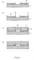
- Fig. 4 illustrates a method of manufacturing the optical disk, for example, shown in Fig. 1.
- the optical disk in Fig. 1 is a medium in which a large quantity of data can be recorded as a hologram. As shown in Fig. 1, the optical disk includes a first substrate 1 positioned on the beam-incident side and a second substrate 2 positioned so as to oppose the first substrate 1.
- Figs. 2 (a), 2 (b) are cross-sectional views of the first substrate 1 and the second substrate 2, respectively.
- the first substrate 1 includes grooves 7 and 8 respectively on the sides of an inner peripheral portion 1a and an outer peripheral portion 1b.
- the diameter of the first substrate is approximately 120 mm and the thickness w 1c of a portion between the inner peripheral portion and the outer peripheral portion is approximately 1.07 mm
- the thickness w 1a of the inner peripheral portion 1a and the thickness w 1b of the outer peripheral portion 1b are approximately 1 mm.
- the depth of the groove is approximately 0. 5 mm
- the width of the groove is approximately 2 mm.
- the second substrate 2 includes projections 2a, 2b on the inner peripheral portion and the outer peripheral portion thereof.
- the diameter of the second substrate is approximately 120 mm
- the diameter of the first substrate is approximately 120 mm
- the thickness w 1c of the portion between the inner peripheral portion and the outer peripheral portion is approximately 1.07 mm
- the heights h 2a , h 2b of the projections are approximately 0.27 mm.
- a space is defined sealing by adhesive agent 6 for bonding the distal end of the inner peripheral portion 1a and the distal end of the projection 2a, and a recording layer 3 is formed in this space.
- the recording layer 3 does not being filled the space, and voids 7 and 8 are formed in the inner peripheral portion 1a and the outer peripheral portion 1b
- a surface of the second substrate 2 opposite from a surface which is in contact with the recording layer 3 is formed with a wavelength adjusting layer 4 of about 20 nm in thickness and a reflecting-layer-mounted address-pit 5 including mirror surfaces for recording beam laminated in this order.
- the first substrate 1 and the second substrate 2 may be formed of various vinyl polymer, polycarbonate, polyarylate, amorphous polyolefin group such as norbornene system, polymethyl methacrylate, cellulose acetate butyrate, polystyrene methyl methacrylate, epoxy resin, and so on.
- the first substrate 1 and the second substrate 2 preferably low in absorption of beam used for recording and are low in birefringence and, in particular, are preferably formed of low birefringence polycarbonate or amorphous polyolefin group.
- the material of the recording layer 3 is a light-cured hologram recording material referred to as photopolymer, and is a material changed in density by recording.
- the photopolymer generally includes free-radical polymerization compound, optical-radical polymerization initiator and matrix material, and may also include acid-forming agent, radial-forming agent, pigment, oligomer, volume expanding agent, and the like.
- the free-radical polymerization compound is preferably a compound including acrylate group, such as a compound in which part of hydrogen is chlorinated such as iso-bornyl acrylate, phenoxy-ethyl acrylate, diethyl glycol monoethyl ether acrylate, ethyl acrylate, vinyl benzoate, or vinyl naphthoate, and a compound added with various substitutional groups such as a group including silicon for enhancing the index difference. More specifically, (trimethylsilylloxy) dimethylsilyl propyl acrylate, (perfluoroxyl) methyl acrylate, and the like. N-vinyl carbazole may also be contained.
- acrylate group such as a compound in which part of hydrogen is chlorinated such as iso-bornyl acrylate, phenoxy-ethyl acrylate, diethyl glycol monoethyl ether acrylate, ethyl acrylate, vinyl benzoate, or vinyl naph
- the optical-radical polymerization compound may be used independently, or by mixing two or more types of the compound.
- the amount of the contained optical-radical polymerization compound is preferably in a range from 5 wt% to 50 wt% with respect to the recording layer.
- the optical-radical polymerization initiator is a compound to initiate polymerization reaction by absorbing beam, and is typically bis (2, 6-difluoro-3-pyrrolphenyl) titanocene, bis( ⁇ 5-cyclopentadienyl)bis(pentafluorophenyl)titanium(IV), and the like.
- the contained quantity of the optical-radical polymerization initiator may be selected as needed according to the wavelength of recording beam, the film thickness of the recording layer, the quantity of beam absorption of the optical-radical polymerization initiator and so on, and is preferably from 0.1 wt% to 5.0 wt%.
- the matrix material may be, for example, various vinyl polymers such as polyvinyl acetate having ester group, polycarbonate, polyalylate, norbornene system resin, polymethylmethacrylate, cellulose acetate butyrate, polystyrenemethylmethacrylate, epoxy resin, and the like.
- the contained quantity of matrix material is preferably from 20 wt% to 80 wt% with respect to the recording layer.
- the arbitrary component contained in the recording layer may be acid-forming agent, free-radical forming agent, pigment, oligomer and the like as described above. These substances can achieve an effect if it is contained on the order of 0.1 wt% with respect to the total amount of recording layer. However, since the sensitivity may be lowered if it is contained excessively, the quantity thereof to be contained is preferably from 0.001 wt% to 0.1 wt%.
- aryl disonium salts for example, aryl disonium salts, diaryl iodonium salts, triaryl sulfonium salts, triaryl selenonium salts, dialkyl phenacyl sulfonium salts, sialkyl-4-hydroxyphenyl sulfonium salts, sulfonic acid ester, iron arene compound, and the like may be used.
- aromatic carbonyl compound in particular, ⁇ , ⁇ -dimetoxy- ⁇ -phenyl acetophenone, and the like may be used.
- the pigment for example, azido system compound, 5-nitroacenaphthene, 1,2-benzanthraquinone, 1-nitro-4-acetylaminonaphthalene, methylene blue, safranine O, malachite green, cyanine colorant, rhodamine colorant may be used.
- oligomer for example, multifunctional resins such as acrylate resin or epoxy resin having functional groups at both ends of a main chain of free-radical polymerization compound after polymerization may be used.
- the wavelength adjusting layer 4 is preferably the one having high reflection factor for a recording beam and high coefficient of transmission for a servo beam.
- the wavelength adjusting layer 4 is preferably the one which reflects the beam of the order of 405 nm and transmits the beam of 670 nm.
- a dichroic mirror which is a beam selecting and transmitting film having a multi-layer construction including layers of high refractive index such as TiO2 or ZnO2 and layers of low refractive index such as SiO2.
- the layer 4 formed by coating pigment which is specifically high in reflecting factor for blue color may also be applicable.
- the reflecting-layer-mounted address-pit 5 is formed by, for example, a concavo-convex structure so as to perform a tracking servo and a focusing servo by a servo beam, and includes information for performing the tracking servo and address information recorded therein in advance.
- a conventional method would be applicable for generating a tracking error, performing tracking servo, generating focusing error and focusing servo.
- a sampled servo system may also be applicable.
- a wobble pit can be employed for performing the tracking servo.
- a liquid-state material are preferable as the material of the adhesive agent 6, and UV-cured adhesive agent or a thermal cured adhesive agent may be employed, for example.
- the pressure in the gaps 7 and 8 is preferably lower than atmospheric pressure and atmospheric air, nitrogen, or inert gas is encapsulated in the gaps 7 and 8, for example.
- the optical disk in Example 1 of the invention preferably simply has a flat-shaped (for example, disk-shaped) recording area, which is irrelevant to the contour of the optical disk.
- the optical disk in Example 1 can also be applied to an optical disk of a triangular, square or hexagonal shape having a size like a business card and including a disk-shaped recording area.
- the optical disk of the invention may be a medium having a cover layer, a recording layer, a gap layer, a reflecting layer, a servo layer, and a base layer laminated in this order from the beam-incident surface.
- the first substrate 1 in Fig. 1 corresponds to the cover layer
- the second substrate 2 corresponds to the gap layer
- the wavelength adjusting layer 4 corresponds to the reflecting layer
- the reflecting-layer-mounted address-pit 5 corresponds to the servo surface
- a third substrate 10 corresponds to the base layer.
- the cover layer and the gap layer transmit the recording beam.
- the servo surface is formed with an emboss pit, a land-and-groove, a wobble pit and the like for performing the focus servo and the tracking servo.
- recording layer precursor solution 3a is filled by 24 ml between the projections 2a and 2b formed on the second substrate 2.
- the recording layer precursor solution is prepared in the following manner. Firstly, vinylcarbazole 11.58 g and vinylpyrrolidone 6.6 g are mixed, and then IRGACURE 784 (Chiba Specialty Chemicals LTD.) 0.3 g is added and stirred. After having dissolved completely, PERBUTYL H (NOF corporation) 0.12 g is mixed to prepare monomer solution A. Subsequently, 1,4-butanediol diglycidylether 30. 3 g and diethylenetriamine 10. 8 g are mixed to prepare epoxy solution B. Then, the monomer solution A 4. 5 ml and the epoxy solution B 25.5 ml are mixed and defoamed to obtain a precursor substance of the optical recording medium.
- the adhesive agent 6 for example, acrylic UV cured adhesive agent NOA 77 manufactured by NORLAND
- the adhesive agent 6 is dropped on the distal ends of the projections 2a, 2b.
- the first substrate 1 and the second substrate 2 are bonded by bonding the distal ends of the projections 2a, 2b, and the distal end portions of the inner peripheral portion 1a and the outer peripheral portion 1b of the first substrate 1 as shown in Fig. 4C.
- a space is defined between the surface of the first substrate 1 and the surface of the second substrate 2 as shown in Fig. 4(c).
- the capacity of the space is on the order of 5 ml.
- the adhesive agent 6 is cured by irradiating UV or heating. At this time, the recording layer precursor solution 3a may be cured.
- the process of bonding the first substrate 1 shown in Fig. 4(c) is performed in vacuum or in a depressurized inert gas. Then, the pressure in the space is lower than the atmospheric pressure.
- the recording layer' precursor substance is converted into the recording layer 3 by being cured under the room temperature or by heat. At this time, since the recording layer precursor solution remaining in the space between the first substrate 1 and the second substrate 2 is contracted in volume by being cured, the voids 7 and 8 are formed at the ends of the recording layer 3 in the space formed between the first substrate 1 and the second substrate 2.
- the depth of the voids 7 and 8 can be selected according to the sensitivity of the recording layer, the diffraction efficiency of the recording layer, the optical concentration of the recording layer, the multiplexing of recording, the sensitivity of the detector, and so on.
- the depth is preferable in the range between 200 ⁇ m and 5000 ⁇ m, for example.
- the optical recording/reproducing device for performing recording and reproduction in the optical disk according to Example 1 will be described as below.
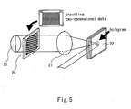
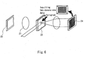
- Fig. 5 and Fig. 6 illustrate an off-axis holographic recording/reproducing device for performing recording and reproduction on the optical disk in this example and a process of recording and reproduction.
- Fig. 7 and Fig. 8 illustrate a coaxial holographic recording/reproducing device for performing recording and reproduction on the optical disk in this example and the process of recording and reproduction.
- a spatial light modulator for providing beam with information a mechanism for forming interference pattern for recording, a beam detector array for detecting a reproduced image and a laser beam source are provided.
- the spatial light modulator the interference pattern forming mechanism, the detector array, the laser beam source and other structures are described in detail.
- the spatial light modulator is arranged on an optical path of a beam, and has pixels two-dimensionally arranged for spatially modulating the beam.
- the spatial light modulator divides the beam into an signal beam area positioned in the central portion thereof and a reference beam area in the peripheral portion.
- spatialally modulate means to modulate the amplitude, the phase, the polarization, and the like.
- the pixels arranged in an irradiating point in the central portion are normally arranged two-dimensionally in a lattice pattern, and correspond to digital information to be recorded in the optical disk.
- the digital information displayed on these pixels corresponds to the quantity of information per page, that is, the quantity of information which can be recorded on the optical disk by one shot of irradiation.
- an irradiating point in the peripheral portion may be formed with a pattern drawn by varying the coefficient of transmission of the beam, and in the case of the reflective spatial light modulator, it may be formed with a pattern drawn by varying the reflecting factor of the optical beam.
- a transmissive liquid crystal panel or the like may be employed as the transmissive spatial light modulator, and a reflective liquid crystal panel, a DMD (Digital Mirror Device) and the like may be employed as the reflective spatial light modulator.
- liquid crystal molecules can be polarized per pixel.
- the coefficient of transmission for beam is adjusted by the polarization of the liquid crystal molecules.
- the reflective liquid crystal panel is the same as the transmissive liquid crystal panel other than that the beam reciprocates in the liquid crystal panel.
- reflection can be adjusted into two directions by using mirrors provided in the respective pixels. By adjusting the direction of reflection of the mirror, a dark state and a bright state are made.
- the mirror rotates around a hinge by an electrostatic attracting force between the mirror and a memory cell provided under the mirror. Normally, the rotation of this mirror is limited by a mechanical stopper to approximately ⁇ 10°.
- the interference pattern forming mechanism is arranged on the optical path of the beam and serves to make the reference beam interfere with the signal beam on the optical path from the above-described spatial light modulator on.
- a 1/4 wave plate 23 and a imaging lens 21 are exemplified as the interference pattern forming mechanism.
- a detector array 24 is arranged at an end of the optical path of the signal beam, and in particular, to detect the beam at the time of reproduction.
- a laser beam source 25 for example, gas laser such as laser diode, He-Ne laser, Ar laser and the like and solid laser such as YAG (LD excitation Nd: YAG laser Nd 3+ :Y 3 Al 5 O 12 ) laser, and the like may be employed.
- gas laser such as laser diode, He-Ne laser, Ar laser and the like
- solid laser such as YAG (LD excitation Nd: YAG laser Nd 3+ :Y 3 Al 5 O 12 ) laser, and the like may be employed.
- a beam provided with a coherence length longer than the optical path difference is used.
- the coherence length is preferably at least 1 mm. It is also possible to feedback the beam as needed in order to elongate the coherence length.
- the optical recording/reproducing device has a drive mechanism and a control mechanism in addition to the structures described above.
- the third substrate 10 having the wavelength adjusting layer 4 and the reflecting-layer-mounted address-pit 5 is bonded to the second substrate 2.
- the reflecting layer in the reflection-layer-mounted address-pit 5 is manufactured by forming a film made of spattering AgNdCu and having a thickness of 200 nm on the surface of the third substrate 10.
- a transparent film (not shown) and having a thickness of 100 nm is manufactured to spatter SiO2 on the reflecting film.
- the wavelength adjusting layer 4 which transmits red beam and reflects blue beam is further provided upon the third substrate 10.
- the photopolymer forming the recording layer 3 is manufactured as shown below. 1,6-hexyandiol diglycidylether (epoxy equivalent 151, Nagase ChemteX Corporation) 45.3 g as diglycidylether and diethylenetriamine 10.14 g as amine are mixed to obtain polymer matrix precursor solution.
- N-vinylcarbazole 4.63 g as the free-radical polymerization compound, N-vinylpirrolidone 2.67 g as the free-radical polymerization compound and IRGACURE 784 (Chiba Specialty Chemicals LTD.) 0.168 g as the optical-radical polymerization initiator are mixed to prepare monomer solution. Then, polymer matrix precursor solution 24 g and monomer solution 6 g are mixed and deformed to obtain photopolymer precursor substance.
- the obtained photopolymer precursor substance 24 ml is filled between the projections 2a, 2b formed on the second substrate 2 as shown in Fig. 4(a), and adhesive agent (acrylic UV cured adhesive agent NOA 77 manufactured by NORLAND) is dropped on the distal ends of the projections 2a, 2b.
- adhesive agent acrylic UV cured adhesive agent NOA 77 manufactured by NORLAND
- the first substrate is bonded to the distal ends of the projections 2a, the first substrate 1 is designed so that the surface of the first substrate 1 is positioned lower than the liquid level of the recording layer precursor solution 3a when bonding with the second substrate 2.
- the space is formed between the surface of the first substrate 1 and the surface of the second substrate 2, and the capacity of the space is on the order of 5 ml.
- the capacity of the space is on the order of 5 ml.
- the adhesive agent 6 is cured by irradiating UV or heating.
- the process of bonding the first substrate 1 is performed in vacuum. Therefore, the pressure in the space is lower than the atmospheric pressure.
- the recording layer precursor solution 3a is converted into the recording layer 3 by blocking beam and held in the room temperature (25°C) for 24 hours.
- the volume of the recording layer 3 is reduced so that the volume of the recording layer is smaller than that of the recording layer precursor solution 3a and hence the void 7 is generated at a distal ends of the space.
- the portion where the recording layer 3 does not exist is not generated in the space other than the void 7. It seems to be because even though the material of the recording layer 3 tends to contract, since the pressure in the void is lower than the atmospheric pressure, the degree of contraction is controlled not to be excessive.
- the device used for the recording and reproduction is the coaxial system as shown in Fig. 7 and Fig. 8 as described above.
- the laser beam source is a laser diode of 407 nm in wavelength and 30 mW in power.
- the DMD Digital Micromirror Device
- the beam which is reflected from the spatial light modulator is expanded to 2.5 mm in radius.
- An area having a radius smaller than 2 mm from the center of the beam is set to be an signal beam area, and an area having a radius from 2 mm to 2.5 mm from the center is set to be a reference beam area.
- the signal beam area has information of 50k bit.
- a beam is irradiated on the recording medium so that a waist portion of the beam where the beam is squeezed most comes to the wavelength adjusting layer 4.
- Information different is recorded from page to page which are different each other by shift multiplexing with the shift distance of 5 ⁇ m using the CLV (Constant Linear Velocity) system.
- the bit error rate is on the order of 10 -5 .
- Example 2 is a card-type medium as shown in Fig. 3.
- the card-type medium includes a first substrate 101 positioned on the beam-incident side and a second substrate 102 facing the first substrate 101 in the same manner as the optical disk in Example 1.
- a space sealed by adhesive agent 106 for bonding the distal ends of the peripheral projections 101a and 101b and the distal end of a projection 102a is formed between the first substrate 101 and the second substrate 102, and the recording layer 103 is formed in this space.
- the recording layer 103 does not fill the space, and voids 107 and 108 are existed at a distal ends of the space.
- a surface of the second substrate 102 opposite from a surface which is in contact with the recording layer 103 is formed with a wavelength adjusting layer 104 of about 20 nm in thickness and a reflecting-layer-mounted address-pit 105 which serve as mirror for the recording beam laminated in this order.
- the material which constitutes the card-type medium is the same as the material of the optical disk in Example 1, and hence description will be omitted.
Landscapes
- Physics & Mathematics (AREA)
- General Physics & Mathematics (AREA)
- Optical Record Carriers And Manufacture Thereof (AREA)
- Optical Recording Or Reproduction (AREA)
- Optical Head (AREA)
- Holo Graphy (AREA)
Abstract
Description
- This application is based upon and claims the benefit of priority from the prior
Japanese Patent Application No.2006 -248591, filed Sep. 13, 2006 - The present invention specifically relates to an optical recording medium in which information can be recorded by hologram and information can be reproduced by irradiating beam, and a method of manufacturing the same.
- A holographic data storage is a memory for recording information in a recording medium using holographic technology by overlapping signal beam having image information and reference beam in the interior of the recording medium and writing interference patterns generated at this time in the recording medium. The recorded information is read by irradiating the reference beam to the recording medium and obtaining the image information from diffraction caused by the interference patterns.
-
U.S. Patent No.5698344 discloses a holographic data storage and a holographic recording/reproducing medium for recording and reproducing information with respect thereto. In the holographic data storage, since the interference patterns are three-dimensionally written using the thickness of the recording medium, selectivity of the wavelength and the angle of beam is high, and hence multiplexing is enabled and high recording capacity is achieved. Since the image information can be read by one shot, it has an advantage such that the transfer rate of reproduced signals is high. - The image information to be recorded is generally encoded digital information. In order to reproduce, the recorded image information is reproduced and decoded to take out as information.
- What is essential to be developed to achieve such a recording is a medium having a thick recording layer in which the interference patterns can be recorded three-dimensionally described in
JP-2001-5368 - The most-used photopolymer as a medium of the holographic data storage achieves recording by generating a density distribution, so that the volume of the recording layer is reduced by recording. When the ratio of volume reduction of the photopolymer is high, the method of reproduction must be thought out. For example, reproduction may be achieved by varying the angle of a disk with respect to reproducing beam or varying the position of a detector for the reproducing beam in the case of off-axis holographic recording, and by varying conversion conditions (decoding condition) of the intensity of the reproducing beam detected by the detector in the case of a coaxial holographic data recording.
- When manufacturing the medium, there arises a problem such that the recording surface area on the medium is reduced in association with volume reduction of a precursor substance when solution as the precursor substance of the recording layer is cured.
- In addition, recording characteristics of photopolymer is affected by oxygen or water in many cases. When the recording material can be isolated from oxygen or water, recording with higher density can be realized.
- An optical recording medium according to an embodiment of the invention includes a first substrate having a groove on the side of an outer peripheral portion thereof; a second substrate in contact with the first substrate in the outer peripheral portion; and a recording layer being disposed in a gap between the first substrate and the second substrate and forming a void in cooperation with the first substrate at the portion of the groove.
-
- Fig. 1 is a vertical cross-sectional view of an optical disk according to Example 1 of the invention;
- Figs. 2(a) and 2(b) are vertical cross-sectional view of a first substrate and a second substrate which constitute the optical disk in Fig. 1;
- Fig. 3 is a vertical cross-sectional view of a card-type medium as an Example 2 of the invention;
- Figs. 4(a), 4(b), 4(c) and 4(d) show a method of manufacturing the optical disk in Example 1 of the invention;
- Fig. 5 shows an off-axis holographic recording/reproducing device and a recording process;
- Fig. 6 shows the off-axis holographic recording/reproducing device and a reproducing process;
- Fig. 7 shows a coaxial holographic recording/reproducing device and a recording process; and
- Fig. 8 shows the coaxial holographic recording/reproducing device and a reproducing process.
- Referring now to the drawings, an embodiment of the invention will be described in detail.
- Fig. 1 is a vertical cross-sectional view of an optical disk as an example of an optical recording medium according to the invention and Figs. 2 (a) and 2(b) are vertical cross-sectional views of a first substrate and a second substrate which constitute the optical disk in Fig. 1. The optical disk in Fig. 1 can be used, for example, for coaxial recording/reproducing system. Fig. 3 is a vertical cross-sectional view of a card-type medium as Example 2 of the invention. Fig. 4 illustrates a method of manufacturing the optical disk, for example, shown in Fig. 1.
- The optical disk in Fig. 1 is a medium in which a large quantity of data can be recorded as a hologram. As shown in Fig. 1, the optical disk includes a
first substrate 1 positioned on the beam-incident side and asecond substrate 2 positioned so as to oppose thefirst substrate 1. - Figs. 2 (a), 2 (b) are cross-sectional views of the
first substrate 1 and thesecond substrate 2, respectively. Thefirst substrate 1 includesgrooves 7 and 8 respectively on the sides of an innerperipheral portion 1a and an outerperipheral portion 1b. When the diameter of the first substrate is approximately 120 mm and the thickness w1c of a portion between the inner peripheral portion and the outer peripheral portion is approximately 1.07 mm, the thickness w1a of the innerperipheral portion 1a and the thickness w1b of the outerperipheral portion 1b are approximately 1 mm. The depth of the groove is approximately 0. 5 mm, and the width of the groove is approximately 2 mm. - The
second substrate 2 includesprojections - As shown in Fig. 1, a space is defined sealing by
adhesive agent 6 for bonding the distal end of the innerperipheral portion 1a and the distal end of theprojection 2a, and arecording layer 3 is formed in this space. Therecording layer 3 does not being filled the space, andvoids 7 and 8 are formed in the innerperipheral portion 1a and the outerperipheral portion 1b - A surface of the
second substrate 2 opposite from a surface which is in contact with therecording layer 3 is formed with a wavelength adjustinglayer 4 of about 20 nm in thickness and a reflecting-layer-mounted address-pit 5 including mirror surfaces for recording beam laminated in this order. - Subsequently, material which forms the optical disk will be described.
- The
first substrate 1 and thesecond substrate 2 may be formed of various vinyl polymer, polycarbonate, polyarylate, amorphous polyolefin group such as norbornene system, polymethyl methacrylate, cellulose acetate butyrate, polystyrene methyl methacrylate, epoxy resin, and so on. Thefirst substrate 1 and thesecond substrate 2 preferably low in absorption of beam used for recording and are low in birefringence and, in particular, are preferably formed of low birefringence polycarbonate or amorphous polyolefin group. - The material of the
recording layer 3 is a light-cured hologram recording material referred to as photopolymer, and is a material changed in density by recording. The photopolymer generally includes free-radical polymerization compound, optical-radical polymerization initiator and matrix material, and may also include acid-forming agent, radial-forming agent, pigment, oligomer, volume expanding agent, and the like. - The free-radical polymerization compound is preferably a compound including acrylate group, such as a compound in which part of hydrogen is chlorinated such as iso-bornyl acrylate, phenoxy-ethyl acrylate, diethyl glycol monoethyl ether acrylate, ethyl acrylate, vinyl benzoate, or vinyl naphthoate, and a compound added with various substitutional groups such as a group including silicon for enhancing the index difference. More specifically, (trimethylsilylloxy) dimethylsilyl propyl acrylate, (perfluoroxyl) methyl acrylate, and the like. N-vinyl carbazole may also be contained.
- The optical-radical polymerization compound may be used independently, or by mixing two or more types of the compound. The amount of the contained optical-radical polymerization compound is preferably in a range from 5 wt% to 50 wt% with respect to the recording layer.
- The optical-radical polymerization initiator is a compound to initiate polymerization reaction by absorbing beam, and is typically bis (2, 6-difluoro-3-pyrrolphenyl) titanocene, bis(η5-cyclopentadienyl)bis(pentafluorophenyl)titanium(IV), and the like. The contained quantity of the optical-radical polymerization initiator may be selected as needed according to the wavelength of recording beam, the film thickness of the recording layer, the quantity of beam absorption of the optical-radical polymerization initiator and so on, and is preferably from 0.1 wt% to 5.0 wt%.
- The matrix material may be, for example, various vinyl polymers such as polyvinyl acetate having ester group, polycarbonate, polyalylate, norbornene system resin, polymethylmethacrylate, cellulose acetate butyrate, polystyrenemethylmethacrylate, epoxy resin, and the like. The contained quantity of matrix material is preferably from 20 wt% to 80 wt% with respect to the recording layer.
- The arbitrary component contained in the recording layer may be acid-forming agent, free-radical forming agent, pigment, oligomer and the like as described above. These substances can achieve an effect if it is contained on the order of 0.1 wt% with respect to the total amount of recording layer. However, since the sensitivity may be lowered if it is contained excessively, the quantity thereof to be contained is preferably from 0.001 wt% to 0.1 wt%.
- As the acid-forming agent, for example, aryl disonium salts, diaryl iodonium salts, triaryl sulfonium salts, triaryl selenonium salts, dialkyl phenacyl sulfonium salts, sialkyl-4-hydroxyphenyl sulfonium salts, sulfonic acid ester, iron arene compound, and the like may be used.
- As the free-radical forming agent, for example, aromatic carbonyl compound, in particular, α,α-dimetoxy-α-phenyl acetophenone, and the like may be used.
- As the pigment, for example, azido system compound, 5-nitroacenaphthene, 1,2-benzanthraquinone, 1-nitro-4-acetylaminonaphthalene, methylene blue, safranine O, malachite green, cyanine colorant, rhodamine colorant may be used.
- As the oligomer, for example, multifunctional resins such as acrylate resin or epoxy resin having functional groups at both ends of a main chain of free-radical polymerization compound after polymerization may be used.
- The
wavelength adjusting layer 4 is preferably the one having high reflection factor for a recording beam and high coefficient of transmission for a servo beam. For example, when a beam having a wavelength on the order of 405 nm is used for the recording beam and red beam having a wavelength on the order of 670 nm is used for a servo beam, thewavelength adjusting layer 4 is preferably the one which reflects the beam of the order of 405 nm and transmits the beam of 670 nm. For example, there is a dichroic mirror which is a beam selecting and transmitting film having a multi-layer construction including layers of high refractive index such as TiO2 or ZnO2 and layers of low refractive index such as SiO2. Thelayer 4 formed by coating pigment which is specifically high in reflecting factor for blue color may also be applicable. - The reflecting-layer-mounted address-
pit 5 is formed by, for example, a concavo-convex structure so as to perform a tracking servo and a focusing servo by a servo beam, and includes information for performing the tracking servo and address information recorded therein in advance. A conventional method would be applicable for generating a tracking error, performing tracking servo, generating focusing error and focusing servo. Although it is preferable to use a continuous servo system to perform the tracking servo, a sampled servo system may also be applicable. For example, a wobble pit can be employed for performing the tracking servo. - A liquid-state material are preferable as the material of the
adhesive agent 6, and UV-cured adhesive agent or a thermal cured adhesive agent may be employed, for example. - The pressure in the
gaps 7 and 8 is preferably lower than atmospheric pressure and atmospheric air, nitrogen, or inert gas is encapsulated in thegaps 7 and 8, for example. - As described thus far, the optical disk in Example 1 of the invention preferably simply has a flat-shaped (for example, disk-shaped) recording area, which is irrelevant to the contour of the optical disk. The optical disk in Example 1 can also be applied to an optical disk of a triangular, square or hexagonal shape having a size like a business card and including a disk-shaped recording area.
- The optical disk of the invention may be a medium having a cover layer, a recording layer, a gap layer, a reflecting layer, a servo layer, and a base layer laminated in this order from the beam-incident surface. The
first substrate 1 in Fig. 1 corresponds to the cover layer, thesecond substrate 2 corresponds to the gap layer, thewavelength adjusting layer 4 corresponds to the reflecting layer, the reflecting-layer-mounted address-pit 5 corresponds to the servo surface, and athird substrate 10 corresponds to the base layer. The cover layer and the gap layer transmit the recording beam. The servo surface is formed with an emboss pit, a land-and-groove, a wobble pit and the like for performing the focus servo and the tracking servo. - Referring now to Fig. 4, a method of manufacturing the optical disk according to Example 1 of the invention will be described.
- As shown in Fig. 4(a), recording
layer precursor solution 3a is filled by 24 ml between theprojections second substrate 2. The recording layer precursor solution is prepared in the following manner. Firstly, vinylcarbazole 11.58 g and vinylpyrrolidone 6.6 g are mixed, and then IRGACURE 784 (Chiba Specialty Chemicals LTD.) 0.3 g is added and stirred. After having dissolved completely, PERBUTYL H (NOF corporation) 0.12 g is mixed to prepare monomer solution A. Subsequently, 1,4-butanediol diglycidylether 30. 3 g anddiethylenetriamine 10. 8 g are mixed to prepare epoxy solution B. Then, themonomer solution A 4. 5 ml and the epoxy solution B 25.5 ml are mixed and defoamed to obtain a precursor substance of the optical recording medium. - Subsequently, as shown in Fig. 4(b), the adhesive agent 6 (for example, acrylic UV cured adhesive agent NOA 77 manufactured by NORLAND) is dropped on the distal ends of the
projections - After having dropped the
adhesive agent 6, thefirst substrate 1 and thesecond substrate 2 are bonded by bonding the distal ends of theprojections peripheral portion 1a and the outerperipheral portion 1b of thefirst substrate 1 as shown in Fig. 4C. When thefirst substrate 1 and thesecond substrate 2 are bonded, a space is defined between the surface of thefirst substrate 1 and the surface of thesecond substrate 2 as shown in Fig. 4(c). The capacity of the space is on the order of 5 ml. When bonding thefirst substrate 1 and thesecond substrate 2, approximately 4.8 ml of the recording layer precursor solution remains in the space. - Subsequently, as shown in Fig. 4(d), the
adhesive agent 6 is cured by irradiating UV or heating. At this time, the recordinglayer precursor solution 3a may be cured. - In the manufacturing method shown above, the process of bonding the
first substrate 1 shown in Fig. 4(c) is performed in vacuum or in a depressurized inert gas. Then, the pressure in the space is lower than the atmospheric pressure. The recording layer' precursor substance is converted into therecording layer 3 by being cured under the room temperature or by heat. At this time, since the recording layer precursor solution remaining in the space between thefirst substrate 1 and thesecond substrate 2 is contracted in volume by being cured, thevoids 7 and 8 are formed at the ends of therecording layer 3 in the space formed between thefirst substrate 1 and thesecond substrate 2. - Although the depth of the
voids 7 and 8 can be selected according to the sensitivity of the recording layer, the diffraction efficiency of the recording layer, the optical concentration of the recording layer, the multiplexing of recording, the sensitivity of the detector, and so on. The depth is preferable in the range between 200 µm and 5000 µm, for example. - Subsequently, the optical recording/reproducing device for performing recording and reproduction in the optical disk according to Example 1 will be described as below.
- Fig. 5 and Fig. 6 illustrate an off-axis holographic recording/reproducing device for performing recording and reproduction on the optical disk in this example and a process of recording and reproduction. Fig. 7 and Fig. 8 illustrate a coaxial holographic recording/reproducing device for performing recording and reproduction on the optical disk in this example and the process of recording and reproduction. In both of these devices, a spatial light modulator for providing beam with information, a mechanism for forming interference pattern for recording, a beam detector array for detecting a reproduced image and a laser beam source are provided.
- Subsequently, the spatial light modulator, the interference pattern forming mechanism, the detector array, the laser beam source and other structures are described in detail.
- The spatial light modulator is arranged on an optical path of a beam, and has pixels two-dimensionally arranged for spatially modulating the beam. For example, in the case of the coaxial system, the beam having passed through the spatial light modulator, the spatial light modulator divides the beam into an signal beam area positioned in the central portion thereof and a reference beam area in the peripheral portion. The term "spatially modulate" means to modulate the amplitude, the phase, the polarization, and the like.
- The pixels arranged in an irradiating point in the central portion are normally arranged two-dimensionally in a lattice pattern, and correspond to digital information to be recorded in the optical disk. The digital information displayed on these pixels corresponds to the quantity of information per page, that is, the quantity of information which can be recorded on the optical disk by one shot of irradiation.
- In the case of the transmissive spatial light modulator, an irradiating point in the peripheral portion may be formed with a pattern drawn by varying the coefficient of transmission of the beam, and in the case of the reflective spatial light modulator, it may be formed with a pattern drawn by varying the reflecting factor of the optical beam. A transmissive liquid crystal panel or the like may be employed as the transmissive spatial light modulator, and a reflective liquid crystal panel, a DMD (Digital Mirror Device) and the like may be employed as the reflective spatial light modulator.
- In the transmissive liquid crystal panel, liquid crystal molecules can be polarized per pixel. The coefficient of transmission for beam is adjusted by the polarization of the liquid crystal molecules. The reflective liquid crystal panel is the same as the transmissive liquid crystal panel other than that the beam reciprocates in the liquid crystal panel. In the DMD, reflection can be adjusted into two directions by using mirrors provided in the respective pixels. By adjusting the direction of reflection of the mirror, a dark state and a bright state are made. The mirror rotates around a hinge by an electrostatic attracting force between the mirror and a memory cell provided under the mirror. Normally, the rotation of this mirror is limited by a mechanical stopper to approximately ± 10°.
- The interference pattern forming mechanism is arranged on the optical path of the beam and serves to make the reference beam interfere with the signal beam on the optical path from the above-described spatial light modulator on.
- More specifically, a 1/4
wave plate 23 and aimaging lens 21 are exemplified as the interference pattern forming mechanism. - A
detector array 24 is arranged at an end of the optical path of the signal beam, and in particular, to detect the beam at the time of reproduction. - As a
laser beam source 25, for example, gas laser such as laser diode, He-Ne laser, Ar laser and the like and solid laser such as YAG (LD excitation Nd: YAG laser Nd3+:Y3Al5O12) laser, and the like may be employed. - When forming the interference patterns using the optical path difference between the recording beam and the reference beam, a beam provided with a coherence length longer than the optical path difference is used. For public use, since the optical path difference is assumed to be at least 1 mm, the coherence length is preferably at least 1 mm. It is also possible to feedback the beam as needed in order to elongate the coherence length.
- The optical recording/reproducing device has a drive mechanism and a control mechanism in addition to the structures described above.
- Subsequently, the optical recording/reproducing experiment using the optical disk shown in Fig. 1 will be described in detail. This experiment, is performed by using the coaxial holographic recording/reproducing device shown in Fig. 6 and Fig. 7.
- As shown in Fig. 1, the
third substrate 10 having thewavelength adjusting layer 4 and the reflecting-layer-mounted address-pit 5 is bonded to thesecond substrate 2. The reflecting layer in the reflection-layer-mounted address-pit 5 is manufactured by forming a film made of spattering AgNdCu and having a thickness of 200 nm on the surface of thethird substrate 10. In addition, a transparent film (not shown) and having a thickness of 100 nm is manufactured to spatter SiO2 on the reflecting film. Thewavelength adjusting layer 4 which transmits red beam and reflects blue beam is further provided upon thethird substrate 10. - The photopolymer forming the
recording layer 3 is manufactured as shown below. 1,6-hexyandiol diglycidylether (epoxy equivalent 151, Nagase ChemteX Corporation) 45.3 g as diglycidylether and diethylenetriamine 10.14 g as amine are mixed to obtain polymer matrix precursor solution. On the other hand, N-vinylcarbazole 4.63 g as the free-radical polymerization compound, N-vinylpirrolidone 2.67 g as the free-radical polymerization compound and IRGACURE 784 (Chiba Specialty Chemicals LTD.) 0.168 g as the optical-radical polymerization initiator are mixed to prepare monomer solution. Then, polymer matrix precursor solution 24 g and monomer solution 6 g are mixed and deformed to obtain photopolymer precursor substance. - As shown in the method of manufacturing the optical disk described above, the obtained
photopolymer precursor substance 24 ml is filled between theprojections second substrate 2 as shown in Fig. 4(a), and adhesive agent (acrylic UV cured adhesive agent NOA 77 manufactured by NORLAND) is dropped on the distal ends of theprojections projections 2a, thefirst substrate 1 is designed so that the surface of thefirst substrate 1 is positioned lower than the liquid level of the recordinglayer precursor solution 3a when bonding with thesecond substrate 2. As shown in Fig. 4(c), the space is formed between the surface of thefirst substrate 1 and the surface of thesecond substrate 2, and the capacity of the space is on the order of 5 ml. When thefirst substrate 1 and thesecond substrate 2 are bonded, approximately 4. 8 ml of recording layer precursor solution remains in the space. - Subsequently, the
adhesive agent 6 is cured by irradiating UV or heating. - The process of bonding the
first substrate 1 is performed in vacuum. Therefore, the pressure in the space is lower than the atmospheric pressure. The recordinglayer precursor solution 3a is converted into therecording layer 3 by blocking beam and held in the room temperature (25°C) for 24 hours. At this time, since the recordinglayer precursor solution 3a purged into the space is contracted in volume by being cured, the volume of therecording layer 3 is reduced so that the volume of the recording layer is smaller than that of the recordinglayer precursor solution 3a and hence the void 7 is generated at a distal ends of the space. The portion where therecording layer 3 does not exist is not generated in the space other than the void 7. It seems to be because even though the material of therecording layer 3 tends to contract, since the pressure in the void is lower than the atmospheric pressure, the degree of contraction is controlled not to be excessive. - The device used for the recording and reproduction is the coaxial system as shown in Fig. 7 and Fig. 8 as described above.
- The laser beam source is a laser diode of 407 nm in wavelength and 30 mW in power. The DMD (Digital Micromirror Device) is used as the spatial light modulator. The beam which is reflected from the spatial light modulator is expanded to 2.5 mm in radius. An area having a radius smaller than 2 mm from the center of the beam is set to be an signal beam area, and an area having a radius from 2 mm to 2.5 mm from the center is set to be a reference beam area. At this time, the signal beam area has information of 50k bit.
- A beam is irradiated on the recording medium so that a waist portion of the beam where the beam is squeezed most comes to the
wavelength adjusting layer 4. Information different is recorded from page to page which are different each other by shift multiplexing with the shift distance of 5 µm using the CLV (Constant Linear Velocity) system. - Experiment is made to reproduce the recording medium using a beam power equivalent to that at the time of recording, the bit error rate is on the order of 10-5.
- Subsequently, Example 2 of the invention will be described as below. Example 2 is a card-type medium as shown in Fig. 3. As shown in Fig. 3, the card-type medium includes a
first substrate 101 positioned on the beam-incident side and a second substrate 102 facing thefirst substrate 101 in the same manner as the optical disk in Example 1. - A space sealed by
adhesive agent 106 for bonding the distal ends of theperipheral projections projection 102a is formed between thefirst substrate 101 and the second substrate 102, and therecording layer 103 is formed in this space. Therecording layer 103 does not fill the space, and voids 107 and 108 are existed at a distal ends of the space. - A surface of the second substrate 102 opposite from a surface which is in contact with the
recording layer 103 is formed with awavelength adjusting layer 104 of about 20 nm in thickness and a reflecting-layer-mounted address-pit 105 which serve as mirror for the recording beam laminated in this order. - Subsequently, the material which constitutes the card-type medium is the same as the material of the optical disk in Example 1, and hence description will be omitted.
- Additional advantages and modifications will readily occur to those skilled in the art. Therefore, the invention in its broader aspects is not limited to the specific details and representative embodiments shown and described herein. Accordingly, various modifications may be made without departing from the spirit or scope of the general inventive concept as defined by the appended claims and their equivalents.
Claims (6)
- An optical recording medium comprising:a first substrate having a groove on the side of an outer peripheral portion thereof;a second substrate in contact with the first substrate in the outer peripheral portion; anda recording layer being disposed in a gap between the first substrate and the second substrate and forming a void in cooperation with the first substrate at the portion of the groove.
- An optical recording medium according to claim 1, wherein the first substrate being formed into a toroidal-shape and having grooves on the sides of an inner peripheral portion and an outer peripheral portion.
- The optical recording medium according to claim 1 or 2, further comprising a wavelength adjusting layer and a reflecting-layer-mounted address-pit formed on a surface opposite from a surface which comes into contact with the recording layer on the second substrate.
- The optical recording medium according to any one of preceding claims 1-3, wherein an oxygen shielding layer is formed on either one of the first substrate and the second substrate.
- A method of manufacturing an optical recording medium comprising:a step of filling a surface of a first substrate, where a groove is formed, with a recording layer precursor solution; anda step of bonding a second substrate with the first substrate in a vacuum atmosphere or a depressurized inert gas atmosphere so as to seal the recording layer precursor solution.
- An optical recording/reproducing device comprising:a spatial light modulator for providing beam with information to be recorded in the optical recording medium according to any one of preceding claims 1-4;a mechanism for receiving beam from the spatial light modulator and forming interference patterns for recording in the optical recording medium;a detector array for detecting a reproducing image from the optical recording medium; anda laser beam source for irradiating the beam.
Applications Claiming Priority (1)
| Application Number | Priority Date | Filing Date | Title |
|---|---|---|---|
| JP2006248591A JP4621646B2 (en) | 2006-09-13 | 2006-09-13 | Holographic data storage medium |
Publications (1)
| Publication Number | Publication Date |
|---|---|
| EP1901290A1 true EP1901290A1 (en) | 2008-03-19 |
Family
ID=38704703
Family Applications (1)
| Application Number | Title | Priority Date | Filing Date |
|---|---|---|---|
| EP07011039A Withdrawn EP1901290A1 (en) | 2006-09-13 | 2007-06-05 | Optical recording medium and method of manufacturing the same |
Country Status (3)
| Country | Link |
|---|---|
| US (1) | US7852537B2 (en) |
| EP (1) | EP1901290A1 (en) |
| JP (1) | JP4621646B2 (en) |
Families Citing this family (2)
| Publication number | Priority date | Publication date | Assignee | Title |
|---|---|---|---|---|
| KR101300812B1 (en) * | 2007-01-05 | 2013-08-26 | 삼성전자주식회사 | Method for recording/reproducing data on/from a holographic storage medium, apparatus therefor and the holographic storage medium |
| CN110249386A (en) * | 2017-02-13 | 2019-09-17 | 松下知识产权经营株式会社 | Cd |
Citations (6)
| Publication number | Priority date | Publication date | Assignee | Title |
|---|---|---|---|---|
| US5698344A (en) * | 1995-11-28 | 1997-12-16 | Sri International | Two-step gated holographic recording in photorefractive materials using cw lasers |
| US6160645A (en) * | 1999-10-26 | 2000-12-12 | Lucent Technologies Inc. | Holographic media |
| US20020145772A1 (en) * | 2001-04-10 | 2002-10-10 | Hegel Ramon F. | Environmentally protected holographic device construction |
| WO2004019139A1 (en) * | 2002-08-20 | 2004-03-04 | Imation Corp. | Fluid containment substrates for holographic media |
| US20060215528A1 (en) * | 2005-03-25 | 2006-09-28 | Kabushiki Kaisha Toshiba | Method of holographic recording and reproduction, holographic recording medium and holographic recording and reproducing apparatus |
| EP1768120A2 (en) * | 2005-09-14 | 2007-03-28 | FUJIFILM Corporation | Optical recording medium and production method thereof, and optical recording apparatus and optical reproducing apparatus |
Family Cites Families (17)
| Publication number | Priority date | Publication date | Assignee | Title |
|---|---|---|---|---|
| JPS5971146A (en) * | 1982-10-14 | 1984-04-21 | Toshiba Corp | Information recording medium |
| JPS5987636A (en) * | 1982-11-10 | 1984-05-21 | Toshiba Corp | Information storage medium |
| US4713314A (en) * | 1984-05-07 | 1987-12-15 | Tdk Corporation | Optical recording medium |
| DE3686081T2 (en) * | 1985-04-17 | 1993-03-18 | Tdk Corp | OPTICAL RECORDING PLATE. |
| US4853260A (en) * | 1987-03-23 | 1989-08-01 | Pioneer Electronic Corporation | Optical disk and process for producing the same |
| JPH0231349A (en) * | 1988-07-21 | 1990-02-01 | Toyobo Co Ltd | Optical recording medium |
| JPH0823941B2 (en) * | 1988-11-08 | 1996-03-06 | パイオニア株式会社 | Optical information recording carrier and manufacturing method thereof |
| DE69033550T2 (en) * | 1989-03-03 | 2001-01-18 | Tdk Corp., Tokio/Tokyo | Medium for optical data storage |
| JP4057746B2 (en) * | 1999-06-18 | 2008-03-05 | 三菱化学株式会社 | Substrate for three-dimensional optical recording medium and method for manufacturing three-dimensional optical recording medium |
| JP4162886B2 (en) * | 2001-12-10 | 2008-10-08 | 新オプトウエア株式会社 | Optical disc recording method, optical disc recording apparatus and optical disc reproducing apparatus |
| JP2004192699A (en) * | 2002-12-10 | 2004-07-08 | Memory Tec Kk | Optical information recording medium |
| JP3896098B2 (en) * | 2003-06-27 | 2007-03-22 | 株式会社東芝 | Hologram recording medium and method for producing the same |
| JP3914211B2 (en) * | 2004-03-03 | 2007-05-16 | 株式会社東芝 | Hologram recording medium |
| JP4185026B2 (en) * | 2004-07-16 | 2008-11-19 | 株式会社東芝 | Hologram recording medium and manufacturing method thereof |
| JP2006154083A (en) * | 2004-11-26 | 2006-06-15 | Toshiba Corp | Hologram recording medium |
| JP2006184897A (en) * | 2004-12-03 | 2006-07-13 | Fuji Photo Film Co Ltd | Optical recording medium filter, optical recording medium, its manufacturing method, optical recording method, and optical reproducing method |
| JP4648726B2 (en) * | 2005-02-25 | 2011-03-09 | アルプス電気株式会社 | Hologram information recording / reproducing method, hologram information reproducing apparatus, and hologram information recording medium |
-
2006
- 2006-09-13 JP JP2006248591A patent/JP4621646B2/en not_active Expired - Fee Related
-
2007
- 2007-06-05 EP EP07011039A patent/EP1901290A1/en not_active Withdrawn
- 2007-09-13 US US11/854,914 patent/US7852537B2/en not_active Expired - Fee Related
Patent Citations (6)
| Publication number | Priority date | Publication date | Assignee | Title |
|---|---|---|---|---|
| US5698344A (en) * | 1995-11-28 | 1997-12-16 | Sri International | Two-step gated holographic recording in photorefractive materials using cw lasers |
| US6160645A (en) * | 1999-10-26 | 2000-12-12 | Lucent Technologies Inc. | Holographic media |
| US20020145772A1 (en) * | 2001-04-10 | 2002-10-10 | Hegel Ramon F. | Environmentally protected holographic device construction |
| WO2004019139A1 (en) * | 2002-08-20 | 2004-03-04 | Imation Corp. | Fluid containment substrates for holographic media |
| US20060215528A1 (en) * | 2005-03-25 | 2006-09-28 | Kabushiki Kaisha Toshiba | Method of holographic recording and reproduction, holographic recording medium and holographic recording and reproducing apparatus |
| EP1768120A2 (en) * | 2005-09-14 | 2007-03-28 | FUJIFILM Corporation | Optical recording medium and production method thereof, and optical recording apparatus and optical reproducing apparatus |
Also Published As
| Publication number | Publication date |
|---|---|
| US20080254262A1 (en) | 2008-10-16 |
| JP4621646B2 (en) | 2011-01-26 |
| US7852537B2 (en) | 2010-12-14 |
| JP2008071405A (en) | 2008-03-27 |
Similar Documents
| Publication | Publication Date | Title |
|---|---|---|
| US7209270B2 (en) | Method and apparatus for phase correlation holographic drive | |
| US7960092B2 (en) | Method of recording in an optical information recording medium | |
| US8247139B2 (en) | Volume holographic data recording media | |
| KR101716500B1 (en) | Optical data storage media and methods for using the same | |
| CN101206891B (en) | Optical Information Recording Medium | |
| JPH11508719A (en) | Optical storage device | |
| US20050233246A1 (en) | Novel optical storage materials, methods of making the storage materials, and methods for storing and reading data | |
| KR20020025702A (en) | Recording apparatus for a holographic recording medium | |
| CN101308674A (en) | Light beam applying method, optical recording medium, and recording and reproducing apparatus | |
| EP1610191A1 (en) | Holographic recording medium and recording method therefor | |
| KR20100074079A (en) | Data storage devices and methods | |
| CN101308675B (en) | Beam applying method and device and optical recording medium | |
| US20080080335A1 (en) | Optical Recording Medium Utilizing Holography and Method for Manufacturing the Same and Optical Recording and Reproducing Apparatus | |
| US7852537B2 (en) | Optical recording medium and method of manufacturing the same | |
| JP2006092677A (en) | Optical information recording / reproducing apparatus and optical information recording method | |
| JP4136713B2 (en) | Multilayer recording medium and multilayer recording system | |
| US20090231979A1 (en) | Optical recording medium | |
| JP4698470B2 (en) | Optical recording medium processing method and processing apparatus, and optical recording / reproducing apparatus | |
| US8541086B2 (en) | Optical information recording medium and method for manufacturing the same | |
| JP4141977B2 (en) | Hologram type optical recording disk | |
| JP2007003692A (en) | Optical recording method, optical recording device, and optical recording medium | |
| JP2006154444A (en) | Hologram recording medium, hologram recording apparatus, and hologram recording method | |
| JP2005266609A (en) | Optical recording medium | |
| JP2004347958A (en) | Optical information recording device | |
| JP2007242193A (en) | Optical recording / reproducing apparatus and data destruction method for optical recording medium |
Legal Events
| Date | Code | Title | Description |
|---|---|---|---|
| PUAI | Public reference made under article 153(3) epc to a published international application that has entered the european phase |
Free format text: ORIGINAL CODE: 0009012 |
|
| 17P | Request for examination filed |
Effective date: 20070605 |
|
| AK | Designated contracting states |
Kind code of ref document: A1 Designated state(s): AT BE BG CH CY CZ DE DK EE ES FI FR GB GR HU IE IS IT LI LT LU LV MC MT NL PL PT RO SE SI SK TR |
|
| AX | Request for extension of the european patent |
Extension state: AL BA HR MK YU |
|
| 17Q | First examination report despatched |
Effective date: 20080619 |
|
| AKX | Designation fees paid |
Designated state(s): DE FR GB |
|
| GRAP | Despatch of communication of intention to grant a patent |
Free format text: ORIGINAL CODE: EPIDOSNIGR1 |
|
| STAA | Information on the status of an ep patent application or granted ep patent |
Free format text: STATUS: THE APPLICATION IS DEEMED TO BE WITHDRAWN |
|
| 18D | Application deemed to be withdrawn |
Effective date: 20090819 |