EP1901114A1 - Affichage électrophorétique et son procédé de commande - Google Patents
Affichage électrophorétique et son procédé de commande Download PDFInfo
- Publication number
- EP1901114A1 EP1901114A1 EP07017716A EP07017716A EP1901114A1 EP 1901114 A1 EP1901114 A1 EP 1901114A1 EP 07017716 A EP07017716 A EP 07017716A EP 07017716 A EP07017716 A EP 07017716A EP 1901114 A1 EP1901114 A1 EP 1901114A1
- Authority
- EP
- European Patent Office
- Prior art keywords
- particles
- color
- charge
- electrophoretic
- display
- Prior art date
- Legal status (The legal status is an assumption and is not a legal conclusion. Google has not performed a legal analysis and makes no representation as to the accuracy of the status listed.)
- Withdrawn
Links
Images


Classifications
-
- G—PHYSICS
- G02—OPTICS
- G02F—OPTICAL DEVICES OR ARRANGEMENTS FOR THE CONTROL OF LIGHT BY MODIFICATION OF THE OPTICAL PROPERTIES OF THE MEDIA OF THE ELEMENTS INVOLVED THEREIN; NON-LINEAR OPTICS; FREQUENCY-CHANGING OF LIGHT; OPTICAL LOGIC ELEMENTS; OPTICAL ANALOGUE/DIGITAL CONVERTERS
- G02F1/00—Devices or arrangements for the control of the intensity, colour, phase, polarisation or direction of light arriving from an independent light source, e.g. switching, gating or modulating; Non-linear optics
- G02F1/01—Devices or arrangements for the control of the intensity, colour, phase, polarisation or direction of light arriving from an independent light source, e.g. switching, gating or modulating; Non-linear optics for the control of the intensity, phase, polarisation or colour
- G02F1/165—Devices or arrangements for the control of the intensity, colour, phase, polarisation or direction of light arriving from an independent light source, e.g. switching, gating or modulating; Non-linear optics for the control of the intensity, phase, polarisation or colour based on translational movement of particles in a fluid under the influence of an applied field
- G02F1/1685—Operation of cells; Circuit arrangements affecting the entire cell
-
- G—PHYSICS
- G02—OPTICS
- G02F—OPTICAL DEVICES OR ARRANGEMENTS FOR THE CONTROL OF LIGHT BY MODIFICATION OF THE OPTICAL PROPERTIES OF THE MEDIA OF THE ELEMENTS INVOLVED THEREIN; NON-LINEAR OPTICS; FREQUENCY-CHANGING OF LIGHT; OPTICAL LOGIC ELEMENTS; OPTICAL ANALOGUE/DIGITAL CONVERTERS
- G02F1/00—Devices or arrangements for the control of the intensity, colour, phase, polarisation or direction of light arriving from an independent light source, e.g. switching, gating or modulating; Non-linear optics
- G02F1/01—Devices or arrangements for the control of the intensity, colour, phase, polarisation or direction of light arriving from an independent light source, e.g. switching, gating or modulating; Non-linear optics for the control of the intensity, phase, polarisation or colour
- G02F1/165—Devices or arrangements for the control of the intensity, colour, phase, polarisation or direction of light arriving from an independent light source, e.g. switching, gating or modulating; Non-linear optics for the control of the intensity, phase, polarisation or colour based on translational movement of particles in a fluid under the influence of an applied field
- G02F1/166—Devices or arrangements for the control of the intensity, colour, phase, polarisation or direction of light arriving from an independent light source, e.g. switching, gating or modulating; Non-linear optics for the control of the intensity, phase, polarisation or colour based on translational movement of particles in a fluid under the influence of an applied field characterised by the electro-optical or magneto-optical effect
- G02F1/167—Devices or arrangements for the control of the intensity, colour, phase, polarisation or direction of light arriving from an independent light source, e.g. switching, gating or modulating; Non-linear optics for the control of the intensity, phase, polarisation or colour based on translational movement of particles in a fluid under the influence of an applied field characterised by the electro-optical or magneto-optical effect by electrophoresis
-
- G—PHYSICS
- G02—OPTICS
- G02F—OPTICAL DEVICES OR ARRANGEMENTS FOR THE CONTROL OF LIGHT BY MODIFICATION OF THE OPTICAL PROPERTIES OF THE MEDIA OF THE ELEMENTS INVOLVED THEREIN; NON-LINEAR OPTICS; FREQUENCY-CHANGING OF LIGHT; OPTICAL LOGIC ELEMENTS; OPTICAL ANALOGUE/DIGITAL CONVERTERS
- G02F1/00—Devices or arrangements for the control of the intensity, colour, phase, polarisation or direction of light arriving from an independent light source, e.g. switching, gating or modulating; Non-linear optics
- G02F1/01—Devices or arrangements for the control of the intensity, colour, phase, polarisation or direction of light arriving from an independent light source, e.g. switching, gating or modulating; Non-linear optics for the control of the intensity, phase, polarisation or colour
- G02F1/165—Devices or arrangements for the control of the intensity, colour, phase, polarisation or direction of light arriving from an independent light source, e.g. switching, gating or modulating; Non-linear optics for the control of the intensity, phase, polarisation or colour based on translational movement of particles in a fluid under the influence of an applied field
- G02F1/1675—Constructional details
- G02F1/16757—Microcapsules
-
- G—PHYSICS
- G02—OPTICS
- G02F—OPTICAL DEVICES OR ARRANGEMENTS FOR THE CONTROL OF LIGHT BY MODIFICATION OF THE OPTICAL PROPERTIES OF THE MEDIA OF THE ELEMENTS INVOLVED THEREIN; NON-LINEAR OPTICS; FREQUENCY-CHANGING OF LIGHT; OPTICAL LOGIC ELEMENTS; OPTICAL ANALOGUE/DIGITAL CONVERTERS
- G02F1/00—Devices or arrangements for the control of the intensity, colour, phase, polarisation or direction of light arriving from an independent light source, e.g. switching, gating or modulating; Non-linear optics
- G02F1/01—Devices or arrangements for the control of the intensity, colour, phase, polarisation or direction of light arriving from an independent light source, e.g. switching, gating or modulating; Non-linear optics for the control of the intensity, phase, polarisation or colour
- G02F1/165—Devices or arrangements for the control of the intensity, colour, phase, polarisation or direction of light arriving from an independent light source, e.g. switching, gating or modulating; Non-linear optics for the control of the intensity, phase, polarisation or colour based on translational movement of particles in a fluid under the influence of an applied field
- G02F1/1675—Constructional details
- G02F2001/1678—Constructional details characterised by the composition or particle type
-
- G—PHYSICS
- G02—OPTICS
- G02F—OPTICAL DEVICES OR ARRANGEMENTS FOR THE CONTROL OF LIGHT BY MODIFICATION OF THE OPTICAL PROPERTIES OF THE MEDIA OF THE ELEMENTS INVOLVED THEREIN; NON-LINEAR OPTICS; FREQUENCY-CHANGING OF LIGHT; OPTICAL LOGIC ELEMENTS; OPTICAL ANALOGUE/DIGITAL CONVERTERS
- G02F2203/00—Function characteristic
- G02F2203/30—Gray scale
-
- G—PHYSICS
- G09—EDUCATION; CRYPTOGRAPHY; DISPLAY; ADVERTISING; SEALS
- G09G—ARRANGEMENTS OR CIRCUITS FOR CONTROL OF INDICATING DEVICES USING STATIC MEANS TO PRESENT VARIABLE INFORMATION
- G09G2300/00—Aspects of the constitution of display devices
- G09G2300/04—Structural and physical details of display devices
- G09G2300/0439—Pixel structures
- G09G2300/0452—Details of colour pixel setup, e.g. pixel composed of a red, a blue and two green components
Definitions
- the present invention relates to an electrophoretic display and a method for driving thereof.
- the electrophoretic display in particular includes a thin film transistor array panel with pixel electrodes, a common electrode panel with a common electrode, and electrically charged particles (electrophoretic particles) between the two panels.
- the electrophoretic particles carrying positive or negative charges, move between the pixel electrodes and the common electrode to provide black-and-white or other color images.
- driving voltages are induced at the electrophoretic particles disposed between the pixel electrodes and the common electrode. These driving voltages drive the electrophoretic particles towards the pixel electrodes or the common electrode. Accordingly, external light incident on the electrophoretic display is absorbed or reflected by the electrophoretic particles located at the common electrode, thereby providing black, white, or other colors such as red, green, or blue.
- the electrophoretic display is able to provide black, white or other colors, which are the colors of the electrophoretic particles.
- the display is inferior to the liquid crystal displays or organic light emitting diode (OLED) displays due to the inferior rendition of various colors and, in particular, of various brightness levels.
- the present invention has been made in an effort to solve the above problem and provide an electrophoretic display that provides many colors, e.g. many brightness levels, and provide a method for driving thereof.
- an electrophoretic display comprising: (a) a first electrode; (b) a second electrode; (c) an electrophoretic member between the first and second electrodes, the electrophoretic member comprising: first particles each of which carries a first charge, second particles each of which carries a second charge, and third particles each of which carries a third charge, the first, second and third charges being different from each other; and a dispersion medium for distributing the first, second and third particles.
- the electrophoretic display comprises circuitry for applying at least six different driving voltages between the first and second electrodes for selectively moving the first, second and third particles relative to at least the first electrode to display different colors.
- the first, second and third charges are all positive or all negative.
- the first, second and third particles are white.
- the second charge is about half of the first charge, and the third charge is about one quarter of the first charge.
- the number of the second particles is about twice the number of the first particles, and the number of the third particles is about four times the number of the first particles.
- each second particle is about twice larger than each first particle, and each third particle is about four times larger than each first particle.
- the electrophoretic member further comprises fourth particles that are white, and a charge of each fourth particle is about one eighth of the first charge.
- the number of the fourth particles is about eight times the number of the first particles
- each fourth particle is about eight times larger than each first particle.
- the electrophoretic member further comprises fifth particles, sixth particles, and seventh particles, the fifth, sixth and seventh particles being black, each fifth particle carrying a fifth charge, each sixth particle carrying a sixth charge, each seventh particle carrying a seventh charge, wherein the fifth, sixth and seventh charges are respectively equal in magnitude but opposite in polarity to the first, second, and third charges.
- the sixth charge is about one half of the fifth charge, and the seventh charge is about one quarter of the fifth charge.
- the number of the sixth particles is about twice the number of the fifth particles, and the number of the seventh particles is about four times the number of the fifth particles.
- each sixth particle is about twice larger than each fifth particle, and each seventh particle is about four times larger than each fifth particle.
- the electrophoretic member further comprises eighth particles that are black, and a charge of each eighth particle is about one eighth of the fifth charge.
- the number of the eighth particles is eight times the number of the fifth particles.
- each eighth particle is eight times larger than each fifth particle.
- the first, second and third particles are respectively red, green, and blue.
- the second charge is about one-half of the first charge
- the third charge is about one quarter of the first charge
- the electrophoretic member further comprises fifth particles, sixth particles, and seventh particles, the fifth, sixth and seventh particles being black, each fifth particle carrying a fifth charge, each sixth particle carrying a sixth charge, each seventh particle carrying a seventh charge, wherein the fifth, sixth and seventh charges are respectively equal in magnitude but opposite in polarity to the first, second, and third charges, wherein the sixth charge is about one half of the fifth charge, and the seventh charge is about one quarter of the fifth charge.
- the electrophoretic member further comprises a capsule confining at least some of the particles and at least some of the dispersion medium.
- the electrophoretic display further comprises a thin film transistor connected to the first electrode.
- Some embodiments of the invention provide a method for driving an electrophoretic display, the electrophoretic display comprising a first electrode, a second electrode, first to third particles between the first and second electrodes, each first particle carrying a first charge, each second particle carrying a second charge, each third particle carrying a third charge, the first, second and third charges being different from each other, the electrophoretic display comprising a dispersion medium for dispersing the first to third particles, the electrophoretic display operable to display at least eight different colors in response to six different voltages, the method comprising applying at least one of the six voltages to position the particles to display one of the eight colors.
- the eight colors are first to eighth colors
- the six voltages are first to sixth voltages
- the method comprises: applying the first voltage to move the first, second and third particles to the first electrode to display the first color; applying the fourth voltage to move the first particles to the second electrode to display the second color; applying the fifth voltage to move the first and second particles to the second electrode to display the fourth color; applying the sixth voltage to move the first to third particles to the second electrode to display the eighth color; applying the third voltage after displaying the fourth color to move the first particles to the first electrode to display the third color; applying the second voltage after displaying the eighth color to move the first and second particles to the first electrode to display the fifth color; applying the fourth voltage after displaying the fifth color to move the first particles to the second electrode to display the sixth color; and applying the third voltage after displaying the eighth color to move the first particles to the first electrode to display the seventh color.
- displaying the second color, the fourth color, and the eighth color are performed after displaying the first color.
- the first voltage, the second voltage, and the third voltage are respectively equal in magnitude but opposite in polarity to the sixth voltage, the fifth voltage, and the fourth voltage.
- the first to third particles are white, and the brightness increases from the first color to the eighth color.
- the electrophoretic display further comprises fourth to sixth particles which are black, each fourth particle carrying an electric charge having the same magnitude but the opposite polarity to the first charge, each fifth particle carrying a charge having the same magnitude but the opposite polarity to the second charge, each sixth particle carrying a charge having the same magnitude but the opposite polarity to the third charge, wherein in the displaying of the first to eighth colors, the fourth to sixth particles move in an opposite direction relative to the first to third particles.
- the first to third particles are respectively red, green, and blue, and the first color is black, the second color is red, the third color is green, the fourth color is yellow, the fifth color is blue, the sixth color is magenta, the seventh color is cyan, and the eighth color is white,
- the electrophoretic display further comprises fourth to sixth particles, each fourth particle carrying a charge having the same magnitude but the opposite polarity to the first charge, each fifth particle carrying a charge having the same magnitude but the opposite polarity to the second charge, each sixth particle carrying a charge having the same magnitude but the opposite polarity to the third charge, wherein in the displaying of the first to eighth colors, the fourth to sixth particles move in an opposite direction relative to the first to third particles.
- Some embodiments provide a method for driving an electrophoretic display, the electrophoretic display comprising a first electrode, a second electrode, first to fourth particles between the first and second electrodes, each first particle carrying a first charge, each second particle carrying a second charge, each third particle carrying a third charge, each fourth particle carrying a fourth charge, the first, second, third and fourth charges being different from each other, the electrophoretic display comprising a dispersion medium for dispersing the first to fourth particles, the electrophoretic display operable to display at least sixteen different colors in response to eight different voltages, the method comprising applying at least one of the eight voltages to position the first to fourth particles to display one of the sixteen colors.
- the sixteen colors are first to sixteenth colors
- the eight voltages are first to eighth voltages
- the method comprises: applying the first voltage to move all of the first to fourth particles to the first electrode to display the first color; applying the fifth voltage to move the first particles to the second electrode to display the second color; applying the sixth voltage to move the first and second particles to the second electrode to display the fourth color; applying the seventh voltage to move the first to third particles to the second electrode to display the eighth color; applying the eighth voltage to move the first to fourth particles to the second electrode to display the sixteenth color; applying the fourth voltage after displaying the fourth color to move the first particles to the first electrode to display the third color; applying the third driving voltage after displaying the eighth color to move the first and second particles to the first electrode to display the fifth color; applying the fifth voltage after displaying the fifth color to move the first particles to the second electrode to display the sixth color; applying the fourth voltage after displaying the eighth color to move the first particles to the seventh color; applying the second voltage after displaying the sixteenth color to move
- displaying of the second color, the fourth color, the eighth color, and the sixteenth color are performed after displaying the first color.
- the eighth voltage, the seventh voltage, the sixth voltage, and the fifth voltage have respectively the same magnitudes but the opposite polarities to the first voltage, the second voltage, the third voltage, and the fourth voltage.
- the first to fourth particles are white, and the brightness increases from the first color to the sixteenth color.
- the electrophoretic display further comprises fifth to eighth particles which are black, each fifth particle carrying a charge having the same magnitude but the opposite polarity to the first charge, each sixth particle carrying a charge having the same magnitude but the opposite polarity to the second charge, each seventh particle carrying a charge having the same magnitude but the opposite polarity to third charge, each eighth particle carrying a charge having the same magnitude but the opposite polarity to fourth charge, wherein in displaying the first to sixteenth colors, the fifth to eighth particles move in an opposite direction relative to the first to fourth particles.
- FIG. 1 is a layout view illustrating the electrophoretic display
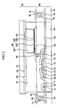
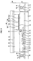
- FIG. 2 is a cross-sectional view taken along the line II-II' shown in FIG.1.
- the electrophoretic display includes a thin film transistor array panel 100, a common electrode panel 200, and an electrophoretic member 300 disposed between the panels 100 and 200.
- each gate line 121 includes a plurality of gate electrodes 124 and also includes an extension ending with an end portion 129 used for making contact to another layer or an external device,
- the gate lines 121 are preferably made of aluminum-containing metals such as aluminum or an aluminum alloy, and/or of silver-containing metals such as silver or a silver alloy, and/or of copper-containing metals such as copper or a copper alloy, and/or of molybdenum-containing metals such as molybdenum or a molybdenum alloy, and/or of chromium, titanium, tantalum, and/or other materials,
- Each gate line 121 includes a lower film and an upper film (not shown) which have different physical characteristics.
- the upper film is preferably made of a low resistivity metal, e.g. an Al-containing metal such as Al or Al alloy, for reducing signal delay or voltage drop along the gate lines 121.
- the lower film is preferably made of a material such as Mo, a Mo alloy, and/or Cr, which makes good contact to other materials such as indium tin oxide (ITO) or indium zinc oxide (IZO).
- ITO indium tin oxide
- IZO indium zinc oxide
- Cr for the lower film and an Al-Nd alloy for the upper film.
- the gate lines 121 may have either a single-layer structure or a triple-layer structure.
- a gate insulating layer 140 preferably made of silicon nitride (SiNx) is formed on the gate lines 121.
- Semiconductor stripes 151 are formed on the gate insulating layer 140. Each semiconductor stripe 151 extends substantially in the longitudinal direction and has a plurality of projections 154 branching out toward the gate electrodes 124. Each semiconductor stripe 151 is widened near the gate lines 121 to cover large areas of the gate lines 121.
- Ohmic contact stripes and islands 161 and 165 are formed on the semiconductor stripes 151.
- Each ohmic contact stripe 161 has a plurality of projections 163, and the projections 163 and the ohmic contact islands 165 are located in pairs on the projections 154 of the semiconductor stripes 151.
- Data lines 171 and drain electrodes 175 are formed on the ohmic contacts 161 and 165, respectively, over the gate insulating layer 140.
- the data lines 171, for transmitting data voltages extend substantially in the longitudinal direction and cross over the gate lines 121.
- Each data line 171 includes a plurality of source electrodes 173 projecting toward the gate electrodes 124 and curved like a character "J", and also includes at the end a widened extension 179 for making contact to another layer or an external device.
- the source electrode 173 and the drain electrode 175 are spaced from each other and are located opposite each other over a corresponding gate electrode 124.
- the data lines 171 and the drain electrodes 175 are preferably made of a refractory metal such as Cr, a molybdenum-containing metal, tantalum, and/or titanium, and may have a multi-layer structure including a lower film (not shown) made of Mo, a Mo alloy, or Cr, and an upper film (not shown) located thereon and made of an Al-containing metal.
- a refractory metal such as Cr, a molybdenum-containing metal, tantalum, and/or titanium
- a multi-layer structure including a lower film (not shown) made of Mo, a Mo alloy, or Cr, and an upper film (not shown) located thereon and made of an Al-containing metal.
- a gate electrode 124, a source electrode 173, and a drain electrode 175 along with a projection 154 of a semiconductor stripe 151 form a thin film transistor (TFT) having a channel in the projection 154 between the source electrode 173 and the drain electrode 175.
- TFT thin film transistor
- the ohmic contacts 161 and 165 are interposed between the underlying semiconductor stripes 151 on the one hand and the overlying data lines 171 and drain electrodes 175 on the other hand to reduce the contact resistance therebetween.
- the semiconductor stripes 151 include a plurality of exposed portions, which are not covered with the data lines 171 and the drain electrodes 175, such as portions located between the source electrodes 173 and the drain electrodes 175. Although the semiconductor stripes 151 are narrower than the data lines 171 at most places, the semiconductor stripes 151 are widened near the gate lines as described above, to enhance the insulation between the gate lines 121 and the data lines 171.
- a passivation layer 180 is a single-layer or multi-layer structure formed on the data lines 171, the drain electrodes 175, and the exposed portions of the semiconductor stripes 151.
- the passivation layer 180 is preferably made of a photosensitive organic material having good flatness, or a low dielectric insulating material such as a-Si:C:O and a-Si:O:F formed by plasma enhanced chemical vapor deposition (PECVD), or an inorganic material such as silicon nitride.
- PECVD plasma enhanced chemical vapor deposition
- the passivation layer 180 can also include an insulating layer (not shown) made of SiNx or SiO 2 under the organic material to prevent the organic material from contacting the semiconductor stripes 151 exposed between the data line 171 and the drain electrode 175,
- the passivation layer 180 has a plurality of contact holes 181, 185, and 182 exposing the end portions 129 of the gate lines 121 and the end portions 179 of the drain electrodes 175 and the data lines 171, respectively.
- Pixel electrodes 190 and contact assistants 81 and 82 are formed on the passivation layer 180.
- the pixel electrodes 190 are physically and electrically connected to the drain electrodes 175 through the contact holes 185 such that the pixel electrodes 190 receive the data voltages from the drain electrodes 175.
- Each pixel electrode 190 can receive at least three positive (+) driving voltages of different magnitudes and at least three negative (-) driving voltages of different magnitudes relative to common electrode 220 on the common electrode panel 200. These voltages change the position of electrophoretic particles 320 dispersed within a dispersion medium 310 so as to represent various colors.
- the contact assistants 81/82 are connected to the exposed end portions 129/179 of the gate lines 121/data lines 171 through the contact holes 181/182.
- the contact assistants 81 and 82 protect the exposed portions of the gate lines 121 and the data lines 171 and enhance the adhesion between these portions and external devices such as integrated circuits which drive the gate lines.
- Partitioning walls 191 including at least one organic or inorganic insulator material and separating the pixel electrodes 190 are formed on the passivation layer 180.
- the partitioning walls 191 surround the pixel electrodes 190 to define pixel volumes filled with the dispersion medium 310 of the electrophoretic member 300.
- the electrophoretic member 300 is located in areas overlying the pixel electrodes 190 and surrounded by the partitioning walls 191.
- the electrophoretic member 300 includes the dispersion medium 310 and electrophoretic particles 320 dispersed in the dispersion medium 310.
- the dispersion medium 310 acts to disperse the electrophoretic particles 320 as the particles move in the medium.
- the dispersion medium 310 is black, i.e. it absorbs external light in order to represent black.
- the electrophoretic particles 320 dispersed in the dispersion medium 310 include first electrophoretic particles 325a, second electrophoretic particles 325b, and third electrophoretic particles 325c, which all have positive charges and are white. In other embodiments, the first to third electrophoretic particle 325a, 325b, and 325c all have negative charges. If the charges are negative, the electrophoretic display can be operated using voltages having the same magnitudes but opposite polarities relative to the electrophoretic display with the positive charges. Operation of the electrophoretic display with the positive charges is explained in detail below.
- the dispersion medium 310 is black and the electrophoretic particles 320 are white. In some embodiments, however, the dispersion medium 310 may be white and the electrophoretic particles 320 may be black.
- each second electrophoretic particle 325b and each third electrophoretic particle 325c are respectively about one-half and one-quarter of the charge of each first electrophoretic particle 325a.
- the charges of the first to third electrophoretic particles 325a, 325b, and 325c are shown respectively as +8, +4, and +2 for the purpose of illustration. However, other charge ratios can also be used.
- the charges of the first to third electrophoretic particles 325a, 325b, and 325c are different respectively, but the present invention is not limited thereto. That is, the first to third electrophoretic particles 325a, 325b, and 325c may have different mass, volume, or buoyancy, etc. from each other, Having different charge, mass, volume, buoyancy, etc means that the threshold driving voltages to move the first to third electrophoretic particles 325a, 325b, and 325c are different.
- the number of the first electrophoretic particles 325a is the same as the number of the second electrophoretic particles 325b, and is the same as the number of the third electrophoretic particles 325c. In some embodiments, however, the number of the second electrophoretic particles 325b and the number of the third electrophoretic particles 325c are respectively about twice and four times larger than the number of the first electrophoretic particles 325a. These numbers can be varied as needed based on the desired gamut of grey levels capable of being displayed using the first to third electrophoretic particles 325a, 325b, and 325c.
- the number of second electrophoretic particles 325b is equal to the number of the third electrophoretic particles 325c and to the number of first electrophoretic particles 325a, and the size of each second electrophoretic particle 325b and the size of each third electrophoretic particle 325c are respectively about twice and four times the size of each first electrophoretic particles 325a.
- Other ratios among the numbers and/or sizes of the electrophoretic particles 325a, 325b, and 325c are also possible.
- the common electrode panel 200 is in tight contact with the partitioning walls 191 to prevent leakage of the dispersion medium 310 from the areas overlying the pixel electrodes 190 and surrounded by the partitioning walls 191.
- the common electrode panel 200 includes an insulation substrate 210 and also includes a common electrode 220 and an organic film 230 sequentially formed on the insulation substrate 210.
- the common electrode 220 is a transparent electrode made of ITO or IZO, and applies a common voltage to the electrophoretic member 300.
- the organic film 230 is a transparent film formed on the common electrode 220 in order to increase the adhesion between the common electrode panel 200 and the partitioning walls 191, The organic film 230 may be omitted.
- Voltage generating circuit 195 (FIG. 1) generates voltages for gate lines 121, data lines 171, and common electrode 200 to provide the driving voltages described above and below.
- This method can be used to display eight black-and-white (grey) brightness levels at each pixel.
- FIGs. 3A to 3G are cross-sectional views of the electrophoretic display which illustrate the method for driving the electrophoretic display according to the exemplary embodiment.
- the threshold driving voltages mentioned with respect to FIGs. 3A to 3G mean voltage differences applied between the pixel electrodes 190 and the common electrode 220 to move the first to third electrophoretic particles 325a, 325b, and 325c from the common electrode 220 to the pixel electrode 190 or from the pixel electrode 190 to the common electrode 220 after overcoming the fluid resistance caused by the dispersion medium 310. That is, the first to third electrophoretic particle 325a, 325b, and 325c have different threshold driving voltages, respectively.
- Each of the first to third electrophoretic particles 325a, 325b, and 325c can move when a voltage bigger than the respective threshold drivings voltages is applied between the pixel electrode 190 and the common electrode 220.
- the method employs up to six different threshold driving voltages (first to sixth threshold driving voltages). Each of these threshold driving voltages is a value obtained by subtracting a pixel electrode's potential from the common electrode's potential.
- the six threshold driving voltages are defined as follows,
- the first threshold driving voltage is a positive (+) voltage that allows all of the first to third electrophoretic particles 325a, 325b, and 325c, with their different charges, to overcome the fluid resistance caused by the dispersion medium 310 and thus move to the pixel electrode 190 from the common electrode 220.
- the second threshold driving voltage is a positive (+) voltage that allows the first electrophoretic particles 325a, having the greatest charge, and the second electrophoretic particles 325b, having the second greatest charge, but not the third electrophoretic particles 325c, to overcome the fluid resistance caused by the dispersion medium 310 and move to the pixel electrode 190 from the common electrode 220.
- the third threshold driving voltage is a positive (+) voltage that allows only the first electrophoretic particles 325a, having the greatest charge, but not the second or third electrophoretic particles 325b and 325c, to overcome the fluid resistance caused by the dispersion medium 310 and move to the pixel electrode 190 from the common electrode 220,
- the fourth threshold driving voltage is a negative (-) voltage that allows only the first electrophoretic particles 325a, having the greatest charge, but not the second or third electrophoretic particles 325b, 325c, to overcome the fluid resistance caused by the dispersion medium 310 and move to the common electrode 220 from the pixel electrode 190.
- the fifth threshold driving voltage is a negative (-) voltage that allows the first electrophoretic particles 325a, having the greatest charge, and the second electrophoretic particles 325b, having the second greatest charge, but not the third electrophoretic particles 325c, to overcome the fluid resistance caused by the dispersion medium 310 and move to the common electrode 220 from the pixel electrode 190.
- the sixth threshold driving voltage is a negative (-) voltage that allows all of the first to third electrophoretic particles 325a, 325b, and 325c to overcome the fluid resistance caused by the dispersion medium 310 and move to the common electrode 220 from the pixel electrode 190.
- Illustrative values of the first to sixth threshold driving voltages are +15V, +10V, +5V, -5V, -10V, and -15V respectively.
- Other threshold driving voltages can also be used.
- the fourth threshold driving voltage (-5V) when the fourth threshold driving voltage (-5V) is provided between the pixel electrode 190 and the common electrode 220 immediately after displaying the first color, only the first electrophoretic particles 325a, having the greatest charge, move to the common electrode 220 from the pixel electrode 190. Accordingly, part of the external light incident through the common electrode panel 200 from the outside is absorbed by the dispersion medium 310, and the rest of the external light is reflected outward by the first electrophoretic particles 325a which have moved to the common electrode 220 to thus contribute to the image formed by the display. Accordingly, the pixel displays the second color which is brighter than black of the first color.
- the fifth threshold driving voltage (-10V) is provided between the pixel electrode 190 and the common electrode 220 immediately after displaying the first color
- the second electrophoretic particles 325b, having the next greatest charge move to the common electrode 220 from the pixel electrode 190.
- the electrophoretic particles reflecting the external light are the first electrophoretic particles 325a and the second electrophoretic particles 325b. Therefore, the fourth color displayed by the pixel is brighter than the second color.
- the third color displayed by the pixel is brighter than the second color and darker than the fourth color.
- the first electrophoretic particles 325a, having the greatest charge, and the second electrophoretic particles 325b, having the next greatest charge move to the pixel electrode 190 from the common electrode 220.
- the dispersion medium 310 part of the external light incident through the common electrode panel 200 from the outside is absorbed by the dispersion medium 310, and the rest of the external light is reflected outward by the third electrophoretic particles 325c remaining at the common electrode 220 to contribute to the displayed image.
- the number of the third electrophoretic particles 325c reflecting the external light is greater than the total number of the first electrophoretic particles 325a and the second electrophoretic particles 325b, so the fifth color displayed by the pixel is brighter than the fourth color.
- the fourth threshold driving voltage (-5V) when the fourth threshold driving voltage (-5V) is provided between the pixel electrode 190 and the common electrode 220 immediately after displaying the fifth color, the first electrophoretic particles 325a, having the greatest charge, move back to the common electrode 220 from the pixel electrode 190.
- the dispersion medium 310 part of the external light incident through the common electrode panel 200 from the outside is absorbed by the dispersion medium 310, and the rest of the external light is reflected outward by the first electrophoretic particles 325a and the third electrophoretic particles 325c, which thus contribute to the displayed image.
- the external light is reflected by the third electrophoretic particles 325c and the first electrophoretic particles 325a. Therefore, the sixth color displayed by the pixel is brighter than the fifth color.
- the total number of the second electrophoretic particles 325b and the third electrophoretic particles 325c reflecting the external light to display white color is greater than the total number of the first electrophoretic particles 325a and the third electrophoretic particles 325c, but less than the total number of the first to third electrophoretic particles 325a, 325b, and 325c. Accordingly, the seventh color displayed by the pixel is brighter than the sixth color and darker than the eighth color.
- each pixel is able to represent eight white (grey) brightness levels, corresponding to the first to eighth colors described above, with the first color corresponding to the lowest brightness and the eighth color corresponding to the highest brightness.
- the ability to display different brightness levels is advantageous in the electrophoretic display.
- electrophoretic display according to this exemplary embodiment is identical to the electrophoretic display of FIGS. 1 and 2, except that electrophoretic member 301 of FIG. 4 includes an additional dispersion medium 330 and capsules 340,
- the additional dispersion medium 330 in each capsule 340 disperses the electrophoretic particles 320 in the capsule.
- Each capsule 340 confines its electrophoretic particles 320 and its dispersion medium 330.
- the additional dispersion medium 330 may be black. If the additional dispersion medium 330 is black, the dispersion medium 310 dispersing the capsules 340 may be omitted,
- the electrophoretic display according to the present exemplary embodiment can be operated using the same method as the electrophoretic display shown in FIGs. 1 and 2, as described above in connection with FIGs. 3A to 3G. Therefore, a detailed description of the operation of the electrophoretic display of FIG. 4 will be omitted,
- FIG. 5 is a cross-sectional view of the electrophoretic display.
- the electrophoretic display of FIG. 5 is identical to the electrophoretic display of FIGs. 1 and 2, except that in electrophoretic member 302 of FIG, 5 the first, second, and third electrophoretic particles 326a, 326b, and 326c are respectively red, green, and blue in color, and are substantially identical in size and number.
- the first to third electrophoretic particles 326a, 326b, and 326c all have negative charges. If the charges are negative, the electrophoretic display can be operated using voltages having the same magnitudes but opposite polarities with respect to the voltages used for the positive charges. Operation of the electrophoretic display in the case of the positive charges is explained in detail below.
- each second electrophoretic particle 326b and the charge of each third electrophoretic particle 326c are respectively about one-half and one-quarter of the charge of each first electrophoretic particle 326a.
- other charge ratios can also be used,
- the number and size of the second electrophoretic particles 326b in some embodiments of the electrophoretic display of FIG. 5 are substantially the same as the number and size of the third electrophoretic particles 326c and are substantially the same as the number and size of the first electrophoretic particles 326a.
- FIGs. 6A to 6G are cross-sectional views of the electrophoretic display which illustrate the method for driving the electrophoretic display according to the exemplary embodiment.
- the first to eighth colors mentioned above with respect to FIGs. 6A to 6G are black, red, green, yellow, blue, magenta, cyan, and white, respectively.
- the threshold driving voltages mentioned below with respect to FIGs. 6A to 6G represent values obtained by subtracting a pixel electrode's potential from the common electrode's potential. These threshold voltages are as follows.
- the first threshold driving voltage is a positive (+) voltage that allows all of the first to third electrophoretic particles 326a, 326b, and 326c, regardless of their charges, to overcome the fluid resistance caused by the dispersion medium 310 and move to the pixel electrode 190 from the common electrode 220.
- the second threshold driving voltage is a positive (+) voltage that allows the first electrophoretic particles 326a, having the greatest charge, and the second electrophoretic particles 326b, having the next greatest charge, but not the third electrophoretic particles 326c, to overcome the fluid resistance caused by the dispersion medium 310 and move to the pixel electrode 190 from the common electrode 220.
- the third threshold driving voltage is a positive (+) voltage that allows only the first electrophoretic particles 326a, having the greatest charge, but not the second or third electrophoretic particles 326b, 326c, to overcome the fluid resistance caused by the dispersion medium 310 and move to the pixel electrode 190 from the common electrode 220.
- the fourth threshold driving voltage is a negative (-) voltage that allows only the first electrophoretic particles 326a, having the greatest charge, but not the second or third electrophoretic particles 326b, 326c, to overcome the fluid resistance caused by the dispersion medium 310 and move to the common electrode 220 from the pixel electrode 190.
- the fifth threshold driving voltage is a negative (-) voltage that allows the first electrophoretic particles 326a, having the greatest charge, and the second electrophoretic particles 326b, having the next greatest charge, but not the third electrophoretic particles 326c to overcome the fluid resistance caused by the dispersion medium 310 and move to the common electrode 220 from the pixel electrode 190.
- the sixth threshold driving voltage is a negative (-) voltage that allows all of the first to third electrophoretic particles 326a, 326b, and 326c to overcome the fluid resistance caused by the dispersion medium 310 and move to the common electrode 220 from the pixel electrode 190.
- Illustrative values of the first to sixth threshold driving voltages are +15V, +10V, +5V, -5V, -10V, and -15V respectively. Other threshold driving voltages can also be used.
- the first threshold driving voltage (+15V) when the first threshold driving voltage (+15V) is provided between a pixel electrode 190 and the common electrode 220, all of the first to third electrophoretic particles 326a, 326b, and 326c move to the pixel electrode 190. Accordingly, external light incident through the common electrode panel 200 from the outside is absorbed by the dispersion medium 310, so the pixel area displays the first color, which is black.
- the pixel area displays yellow, the fourth color, which is a mixture of red and green.
- the pixel area displays green color which is the second color and is the color of the second electrophoretic particles 326a.
- the sixth threshold driving voltage (-15V) when the sixth threshold driving voltage (-15V) is provided between the pixel electrode 190 and the common electrode 220 after displaying the first color, all of the first to third electrophoretic particles 326a, 326b, and 326c move to the common electrode 220 from the pixel electrode 190. Accordingly, most of the external light incident through the common electrode panel 200 from the outside is reflected outward by the first to third electrophoretic particles 326a, 326b, and 326c. As a result, the pixel area displays white, the eighth color, which is a mixture of red, green, and blue.
- the pixel area displays blue, the fifth color, which is the color of the third electrophoretic particles 326c.
- each pixel can represent eight different colors, i.e. the first color through the eighth color, which is the brightest color, via an application of at least one of the first to sixth threshold driving voltages.
- the electrophoretic display operated as in FIG. 5 and FIGs. 6A to 6G can display a large number of colors.
- FIG. 7 is a cross-sectional view of the electrophoretic display according to this exemplary embodiment.
- the electrophoretic display of FIG. 7 is identical to the electrophoretic display of FIG. 5, except that electrophoretic member 303 of FIG. 7 includes an additional dispersion medium 330 in capsules 340.
- each capsule 340 disperses the electrophoretic particles 321 in the capsule.
- Each capsule 340 confines its electrophoretic particles 321 and its dispersion medium 330. If the additional dispersion medium 330 is black, the dispersion medium 310 dispersing the capsules 340 may be omitted.
- the electrophoretic display according to FIG. 7 can be operated using the same method as the electrophoretic display of FIG. 5, Therefore a detailed description of operation of the electrophoretic display of Fig. 7 will be omitted.
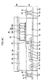
- FIG. 8 is a cross-sectional view of the electrophoretic display.
- the electrophoretic display of FIG. 8 is identical to the electrophoretic display of PIGs.1 and 2, except that electrophoretic particles 322 of an electrophoretic member 304 of the electrophoretic display of FIG. 8 include additional black, negatively charged particles 325e ("fifth electrophoretic particles"), 325f (“sixth electrophoretic particles”) and 325g (“seventh electrophoretic particles”). These particles are provided in addition to the first electrophoretic particles 325a, second electrophoretic particles 325b, and third electrophoretic particles 325c.
- the first to third electrophoretic particles 325a, 325b, and 325c are all negatively charged, and the fifth to seventh electrophoretic particles 325e, 325f, and 325g are all positively charged.
- each sixth electrophoretic particle 325f and each seventh electrophoretic particles 325g are respectfully about one-half and one-quarter of the charge of each fifth electrophoretic particles 325e.
- the charge of each first electrophoretic particle 325a is about the same as the charge of each fifth electrophoretic particles 325e.
- the charges of the fifth to seventh electrophoretic particles 325e, 325f, and 325g are shown as -8, -4, and -2, respectively, for the convenience of understanding.
- other charge ratios can be used for the fifth to seventh electrophoretic particles 325e, 325f, and 325g.
- the number of the fifth electrophoretic particles 325e is the same as for the electrophoretic particles 325f and the same as for the seventh electrophoretic particles 325g, but in practice, in some embodiments the number of the sixth electrophoretic particles 325f and the number of the seventh electrophoretic particles 325g are respectively about twice and four times larger than the number of the fifth electrophoretic particles 325e. This is done to make the numbers of the fifth, sixth, and seventh electrophoretic particles consistent with the numbers of the first to third electrophoretic particles 325a, 325b, and 325c.
- the number of the sixth electrophoretic particles 325f and the number of the seventh electrophoretic particles 325g may each be substantially equal to the number of the fifth electrophoretic particles 325e, and the size of each sixth electrophoretic particle 325f and the size of each seventh electrophoretic particle 325g may respectively be about twice and four times larger than the size of each fifth electrophoretic particle 325e.
- the numbers and sizes of the fifth to seventh electrophoretic particles 325e, 325f, and 325g may also be set to other ratios.
- the electrophoretic display of FIG. 8 is operated using a method identical to the method described above for driving the electrophoretic display of FIGs. 1 and 2, except that the electrophoretic member 304 can display additional black-and-white gray levels depending on the position of the fifth to seventh electrophoretic particles 325e, 325f, and 325g.
- the electric field pushes these particles in the opposite direction relative to the first to third electrophoretic particles 325a, 325b, and 325c.
- a detailed description of the operation of the electrophoretic display of FIG. 8 will be omitted.
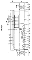
- FIG. 9 An electrophoretic display according to another exemplary embodiment of the present invention is shown in FIG. 9.
- FIG. 9 is a cross-sectional view of the electrophoretic display.
- electrophoretic display of FIG. 9 is identical to the electrophoretic display of FIGs.1 and 2, except that electrophoretic particles 323 of electrophoretic member 305 of FIG. 9 include additional ("fourth") white-colored electrophoretic particles 325d.
- each fourth electrophoretic particle 325d is about one eighth of the charge of each first electrophoretic particle 325a.
- the charges of the first to fourth electrophoretic particles 325a, 325b, 325c, and 325d are shown respectively as +8, +4, +2, and +1 for the convenience of understanding.
- the numbers, charges or sizes of the electrophoretic particles 325a, 325b, 325c, and 325d may be set to other ratios.
- FIG. 9 shows equal numbers of each of the first to fourth electrophoretic particles 325a, 325b, 325c, and 325d
- the number of the second electrophoretic particles 325b, the number of the third electrophoretic particles 325c, and the number of the fourth electrophoretic particles 325d are respectively about twice, four times, and eight times larger than the number of the first electrophoretic particles 325a.
- the respective numbers of these different types of the electrophoretic particles may vary relative to each other, and can be chosen based on the desired grey levels that the electrophoretic display is to reproduce.
- the number of the second electrophoretic particles 325b, the number of the third electrophoretic particles 325c, and the number of the fourth electrophoretic particles 325d may each be substantially the same as the number of the first electrophoretic particles 325a, and the size of each second electrophoretic particle 325b, the size of each third electrophoretic particle 325c, and the size of each fourth electrophoretic particle 325d may respectively be about twice, four times, and eight times as large as the size of each first electrophoretic particle 325a.
- Other relationships between the numbers or sizes of the first to fourth electrophoretic particles 325a, 325b, 325c, and 325d are also possible.
- the addition of the fourth electrophoretic particles 325d in FIG. 9 makes it possible to display sixteen colors from the first, darkest, black color, and up to the sixteenth, white color.
- the first to eighth threshold driving voltages mentioned with respect to FIG. 9 each represent a value obtained by subtracting a pixel electrode's potential from the common electrode's potential.
- the first threshold driving voltage is a positive (+) voltage that allows all of the first to fourth electrophoretic particles 325a, 325b, 325c, and 325d, with their different charges, to overcome the fluid resistance caused by the dispersion medium 310 and move to the pixel electrode 190 from the common electrode 220.
- the second threshold driving voltage is a positive (+) voltage that allows only the first to third electrophoretic particles 325a, 325b, and 325c, but not the fourth electrophoretic particles 325d, to overcome the fluid resistance caused by the dispersion medium 310 and move to the pixel electrode 190 from the common electrode 220.
- the third threshold driving voltage is a positive (+) voltage that allows the first electrophoretic particles 325a, having the greatest charge, and the second electrophoretic particles 325b, having the next greatest charge, but not the third or fourth electrophoretic particles 325c, 325d, to overcome the fluid resistance caused by the dispersion medium 310 and move to the pixel electrode 190 from the common electrode 220,
- the fourth threshold driving voltage is a positive (+) voltage that allows the first electrophoretic particles 325a, having the greatest charge, but not the second to fourth electrophoretic particles 325b, 325c, 325d, to overcome the fluid resistance caused by the dispersion medium 310 and move to the pixel electrode 190 from common electrode 220.
- the fifth threshold driving voltage is a negative (-) voltage that allows only the first electrophoretic particles 325a, having the greatest charge, but not the second to fourth electrophoretic particles 325b, 325c, 325d, to overcome the fluid resistance caused by the dispersion medium 310 and move to the common electrode 220 from the pixel electrode 190.
- the sixth threshold driving voltage is a negative (-) voltage that allows the first electrophoretic particles 325a, having the greatest charge, and the second electrophoretic particles 325b, having the next greatest charge, but not the third and fourth electrophoretic particles 325c, 325d, to overcome the fluid resistance caused by the dispersion medium 310 and move to the common electrode 220 from the pixel electrode 190.
- the seventh threshold driving voltage is a negative (-) voltage that allows the first to third electrophoretic particles 325a, 325b, and 325c to overcome the fluid resistance of the dispersion medium 310 and move to the common electrode 220 from the pixel electrode 190.
- the eighth threshold driving voltage is a negative (-) voltage that allows all of the first to fourth electrophoretic particles 325a, 325b, 325c, and 325d to overcome the fluid resistance caused of the dispersion medium 310 and move to the common electrode 220 from the pixel electrode 190.
- the first to eighth threshold driving voltages are, respectively, +40V, +20V, +10V, +5V, -5V, -10V, -20V, and -40V.
- the method for driving the electrophoretic display to provide the first color will be described.
- the first threshold driving voltage (+40V) is applied, all of the first to fourth electrophoretic particles 325a, 325b, 325c, and 325d move to the pixel electrode 190. Accordingly, external light incident through the common electrode panel 200 from the outside is absorbed by the dispersion medium 310, so the pixel area is the first color, which is the darkest black.
- the fifth threshold driving voltage (-5V) is applied immediately after displaying the first color
- only the first electrophoretic particles 325a, having the greatest charge move to the common electrode 220 from the pixel electrode 190. Accordingly, part of the external light incident through the common electrode panel 200 from the outside is absorbed by the dispersion medium 310, and the remaining part of the external light is reflected outward by the first electrophoretic particles 325a located at the common electrode 220 to thus contribute to the displayed color. Accordingly, the resulting color of the pixel is the second color, which is brighter than the first, black, color.
- the sixth threshold driving voltage (-10V) is applied immediately after displaying the first color
- only the first electrophoretic particles 325a, having the greatest charge, and the second electrophoretic particles 325b, having the next greatest charge move to the common electrode 220 from the pixel electrode 190.
- part of the external light incident through the common electrode panel 200 from the outside is absorbed by the dispersion medium 310, and the remaining part of the external light is reflected outward by the first electrophoretic particles 325a and the second electrophoretic particles 325b located at the common electrode 220 to contribute to the displayed color.
- the electrophoretic particles reflecting the external light are the first electrophoretic particles 325a and the second electrophoretic particles 325b, Consequently, the pixel is the fourth color, which is brighter than the second color.
- the number of the second electrophoretic particles reflecting the external light and providing white is greater than that of the first electrophoretic particles 325a but less than the total number of the first electrophoretic particles 325a and the second electrophoretic particles 325b, Accordingly, the third color obtained at the pixel is brighter than the second color and darker than the fourth color.
- the seventh threshold driving voltage (-20V) is applied after displaying the first color
- the first to third electrophoretic particles 325a, 325b, and 325c move to the common electrode 220 from the pixel electrode 190. Accordingly, part of the external light incident through the common electrode panel 200 from the outside is absorbed by the dispersion medium 310, and the remaining part of the external light is reflected outward by the first to third electrophoretic particles 325a, 325b, and 325c located at the common electrode 220 and thus contributing to the displayed color.
- the total number of the first to third electrophoretic particles 325a, 325b, and 325c reflecting the external light and providing white is greater than the total number of the first electrophoretic particles 325a and the second electrophoretic particles 325b, so the eighth color provided at the pixel is brighter than the fourth color.
- the third threshold driving voltage (+10V) is applied immediately after displaying the eighth color
- the second electrophoretic particles 325b, having the next greatest charge move to the pixel electrode 190 from the common electrode 220. Accordingly, part of the external light incident through the common electrode panel 200 from the outside is absorbed by the dispersion medium 310, and the remaining part of the external light is reflected outward by the third electrophoretic particles 325c remaining at the common electrode 220 to contribute to the displayed color.
- the number of the third electrophoretic particles 325c reflecting the external light is greater than the total number of the first electrophoretic particles 325a and the second electrophoretic particles 325b, so the fifth color provided at the pixel is brighter than the fourth color.
- the fifth threshold driving voltage (-5V) is applied immediately after displaying the fifth color
- the first electrophoretic particles 325a having the greatest charge, move back to the common electrode 220 from the pixel electrode 190. Accordingly, part of the external light incident through the common electrode panel 200 from the outside is absorbed by the dispersion medium 310, and the remaining part of the external light is reflected outward by the first electrophoretic particles 325a and the third electrophoretic particles 325c to contribute to the displayed color.
- the total number of the first electrophoretic particles 325a and the third electrophoretic particles 325c reflecting the external light is greater than the number of the third electrophoretic particles 325c, so the sixth color provided at the pixel is brighter than the fifth color.
- the fourth threshold driving voltage (+5V) is applied immediately after displaying the eighth color
- the first electrophoretic particles 325a having the greatest charge, move to the pixel electrode 190 from the common electrode 220. Accordingly, part of the external light incident through the common electrode panel 200 from the outside is absorbed by the dispersion medium 310, and the remaining part of the external light is reflected outward by the second electrophoretic particles 325b and the third electrophoretic particles 325c to contribute to the displayed color.
- the total number of the second electrophoretic particles 325b and third electrophoretic particles 325c reflecting the external light is greater than the total number of the first electrophoretic particles 325a and the third electrophoretic particles 325c but less than the total number of the first to third electrophoretic particles 325a, 325b, and 325c, so the seventh color provided at the pixel is brighter than either the sixth color or the eighth color.
- the eighth threshold driving voltage (-40V) is applied after displaying the first color
- the first to fourth electrophoretic particles 325a, 325b, 325c, and 325d move to the common electrode 220 from the pixel electrode 190. Accordingly, most of the external light incident through the common electrode panel 200 from the outside is reflected outward by the first to fourth electrophoretic particles 325a, 325b, 325c, and 325d, to thus display the sixteenth color which is the brightest white color.
- the first electrophoretic particles 325a, second electrophoretic particles 325b, and third electrophoretic particles 325c move to the pixel electrode 190 from the common electrode 220. Accordingly, part of the external light incident through the common electrode panel 200 from the outside is absorbed by the dispersion medium 310, and the remaining part of the external light is reflected outward by the fourth electrophoretic particles 325d remaining at the common electrode 220 to contribute to the displayed color.
- the number of the fourth electrophoretic particles 325d reflecting the external light is greater than the total number of the first to third electrophoretic particles 325a, 325b, and 325c, so the ninth color provided at the pixel is brighter than the eighth color,
- the first electrophoretic particles 325a move to the common electrode 220 from the pixel electrode 190. Accordingly, part of the external light incident through the common electrode panel 200 from the outside is absorbed by the dispersion medium 310, and the remaining part of the external light is reflected outward by the first electrophoretic particles 325a and fourth electrophoretic particles 325d remaining at the common electrode 220 to contribute to the displayed color. At this time, the total number of the first and fourth electrophoretic particles 325a and 325d reflecting the external light is greater than the number of the fourth electrophoretic particles 325d, so the tenth color provided at the pixel is brighter than the ninth color.
- the dispersion medium 310 part of the external light incident through the common electrode panel 200 from the outside is absorbed by the dispersion medium 310, and the remaining part of the external light is reflected outward by the first electrophoretic particles 325a, second electrophoretic particles 325b, and fourth electrophoretic particles 325d remaining at the common electrode 220 to contribute to the displayed color,
- the total number of the first electrophoretic particles 325a, second electrophoretic particles 325b, and fourth electrophoretic particles 325d reflecting the external light is greater than the total number of the first electrophoretic particles 325a and the fourth electrophoretic particles 325d, so the twelfth color provided at the pixel is brighter than the ninth color.
- the eleventh color provided at the pixel is brighter overall than the tenth color and darker than the twelfth color
- the third threshold driving voltage (+10V) is applied after displaying the sixteenth color
- the first electrophoretic particles 325a and the second electrophoretic particles 325b move to the pixel electrode 190 from the common electrode 220. Accordingly, part of the external light incident through the common electrode panel 200 from the outside is absorbed by the dispersion medium 310, and the remaining part of the external light is reflected outward by the third electrophoretic particles 325c and fourth electrophoretic particles 325d remaining at the common electrode 220 to contribute to the displayed color.
- the total number of the third electrophoretic particles 325c and fourth electrophoretic particles 325d reflecting the external light is greater than the total number of the first electrophoretic particles 325a, second electrophoretic particles 325b, and fourth electrophoretic particles 325d, so the thirteenth color provided at the pixel is brighter than the twelfth color.
- the dispersion medium 310 part of the external light incident through the common electrode panel 200 from the outside is absorbed by the dispersion medium 310, and the remaining part of the external light is reflected outward by the first electrophoretic particles 325a, third electrophoretic particles 325c, and fourth electrophoretic particles 325d remaining at the common electrode 220 to contribute to the displayed color,
- the total number of the first electrophoretic particles 325a, third electrophoretic particles 325c and fourth electrophoretic particles 325d reflecting the external light is greater than the total number of the third electrophoretic particles 325c and fourth electrophoretic particles 325d, so the fourteenth color provided at the pixel is brighter than the thirteenth color
- the total number of the second electrophoretic particles 325b, third electrophoretic particles 325c and fourth electrophoretic particles 325d reflecting the external light is greater than the total number of the first electrophoretic particles 325a, third electrophoretic particles 325c, and fourth electrophoretic particles 325d but less than the total number of the first to fourth electrophoretic particles 325a, 325b, 325c, and 325d. Accordingly, the fifteenth color provided at the pixel is brighter than the fourteenth color and darker than the sixteenth color.
- each pixel can provide eight different levels of black-and-white brightness, starting from the first, darkest color and up to the sixteenth, brightest color, when at least one of the first to eighth threshold driving voltages is applied.
- the present exemplary embodiment of the present invention advantageously provides a large number of brightness levels from black to white.
- the electrophoretic particles 323 additionally include fifth electrophoretic particles (not shown) colored white.
- the charge of each fifth electrophoretic particle is about one sixteenth of the charge of one first electrophoretic particle 325a.
- the number of the fifth electrophoretic particles may be about 16 times larger than the number of the first electrophoretic particles 325a, or the size of each fifth electrophoretic particle may be about 16 times larger than the size of one first electrophoretic particle 325a.
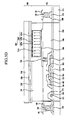
- FIG. 10 is a cross-sectional view of the electrophoretic display according to that embodiment.
- the electrophoretic display of FIG. 10 is identical to the electrophoretic display of FIG. 9, except that electrophoretic particles 324 of electrophoretic member 306 of FIG. 10 include additional, black, negatively charged electrophoretic particles. More particularly, in addition to the first electrophoretic particles 325a, second electrophoretic particles 325b, third electrophoretic particles 325c, and fourth electrophoretic particles 325d, the electrophoretic particles 324 include black, negatively charged fifth electrophoretic particles 325e, sixth electrophoretic particles 325f, seventh electrophoretic particles 325g, and eighth electrophoretic particles 325h.
- the first to fourth electrophoretic particles 325a, 325b, 325c, and 325d all have negative charges
- the fifth to eighth electrophoretic particles 325e, 325f, 325g, and 325h all have positive charges.
- each sixth electrophoretic particle 325f, the charge of each seventh electrophoretic particle 325g, and the charge of each eighth electrophoretic particle 325h are respectively about one-half, one quarter, and one eighth of the charge of each fifth electrophoretic particles 325e.
- the charge of each first electrophoretic particle 325a and the charge of each fifth electrophoretic particle 325e are substantially identical.
- the charges of the fifth to eighth electrophoretic particles 325e, 325f, 325g, and 325h are shown as -8, -4, and -2, respectively, for the convenience of understanding, However, the charges of the fifth to eighth electrophoretic particles 325e, 325f, 325g, and 325h may be set to other ratios.
- FIG. 10 shows equal numbers of the fifth to eighth electrophoretic particles 325e, 325f, 325g, and 325h
- the sixth electrophoretic particles 325f, seventh electrophoretic particles 325g, and eighth electrophoretic particles 325h are respectively twice, four times, and eight times as many as the fifth electrophoretic particles 325e. This is done to make the numbers of the fifth, sixth, seventh, and eighth electrophoretic particles consistent with the numbers of the first to fourth electrophoretic particles 325a, 325b, 325c, and 325d.
- the number of the sixth electrophoretic particles 325g, the number of the seventh electrophoretic particles 325g, and the number the eighth electrophoretic particles 325g may each be substantially the same as the number of the fifth electrophoretic particles 325e, and the size of each sixth electrophoretic particle 325f, the size of each seventh electrophoretic particle 325g, and the size of each eighth electrophoretic particle 325h may respectively be about twice, four times, and eight times larger than the size of each fifth electrophoretic particle 325e. Other ratios for the numbers and sizes of the fifth to eighth electrophoretic particles 325e, 325f, 325g, and 325h are also possible.
- the electrophoretic display of FIG. 10 can be operated using the same method as the electrophoretic display of FIG. 9, except that the electrophoretic member 306 of FIG.10 provides sixteen levels of black and white brightness, beginning with the first, black color and ending with the sixteenth, white color, and the fifth to eighth electrophoretic particles 325e, 325f, 325g, and 325h move in the opposite direction relative to the first to fourth electrophoretic particles 325a, 325b, 325c, and 325d with respect to each threshold driving voltage applied to the electrophoretic member 306.
- the electrophoretic member 306 of FIG.10 provides sixteen levels of black and white brightness, beginning with the first, black color and ending with the sixteenth, white color
- the fifth to eighth electrophoretic particles 325e, 325f, 325g, and 325h move in the opposite direction relative to the first to fourth electrophoretic particles 325a, 325b, 325c, and 325d with respect to each threshold driving voltage applied to the electrophoretic member 306.
- the electrophoretic particles 324 are placed into additional dispersion medium 330 (not shown in FIG.10) located in capsules 340, as in FIG. 4.
- FIG. 11 is a cross-sectional view of the electrophoretic display according to that embodiment.
- the electrophoretic display of FIG. 11 is identical to the electrophoretic display of FIG. 7, except that the capsules 340 of electrophoretic member 307 of FIG. 11 are not kept in place by dispersion medium 310 contained within partitioning walls 191, but rather are affixed to the pixel electrodes 190 by a binder 350.
- the electrophoretic display of FIG. 11 has a sealant 400 formed along the periphery of thin film transistor array panel 101 and common electrode panel 200 in order to fix together the thin film transistor array panel 101 and the common electrode panel 200 and to keep moisture and impurities out of the electrophoretic display.
- the electrophoretic display of FIG.11 and its operation, can be as in FIGs. 1, 2, and 3A to 3G, to provide the same kind of display.
- Some embodiments of the present invention thus include electrophoretic displays and methods of operation of the electrophoretic displays. Some embodiments provide different brightness levels and colors. While this invention has been described in connection with what is presently considered to be practical exemplary embodiments, it is to be understood that the invention is not limited to the disclosed embodiments, but, on the contrary, is intended to cover various modifications and equivalent arrangements as defined by the appended claims.
Landscapes
- Physics & Mathematics (AREA)
- Nonlinear Science (AREA)
- General Physics & Mathematics (AREA)
- Optics & Photonics (AREA)
- Health & Medical Sciences (AREA)
- Life Sciences & Earth Sciences (AREA)
- Chemical & Material Sciences (AREA)
- Chemical Kinetics & Catalysis (AREA)
- Electrochemistry (AREA)
- Molecular Biology (AREA)
- Control Of Indicators Other Than Cathode Ray Tubes (AREA)
- Electrochromic Elements, Electrophoresis, Or Variable Reflection Or Absorption Elements (AREA)
Applications Claiming Priority (1)
| Application Number | Priority Date | Filing Date | Title |
|---|---|---|---|
| KR1020060088050A KR20080023913A (ko) | 2006-09-12 | 2006-09-12 | 전기 영동 표시 장치 및 그 구동 방법 |
Publications (1)
| Publication Number | Publication Date |
|---|---|
| EP1901114A1 true EP1901114A1 (fr) | 2008-03-19 |
Family
ID=38692022
Family Applications (1)
| Application Number | Title | Priority Date | Filing Date |
|---|---|---|---|
| EP07017716A Withdrawn EP1901114A1 (fr) | 2006-09-12 | 2007-09-11 | Affichage électrophorétique et son procédé de commande |
Country Status (3)
| Country | Link |
|---|---|
| US (1) | US20080062159A1 (fr) |
| EP (1) | EP1901114A1 (fr) |
| KR (1) | KR20080023913A (fr) |
Cited By (2)
| Publication number | Priority date | Publication date | Assignee | Title |
|---|---|---|---|---|
| CN104813385A (zh) * | 2012-10-02 | 2015-07-29 | 电子墨水加利福尼亚有限责任公司 | 彩色显示装置 |
| EP3221744A4 (fr) * | 2014-11-17 | 2018-04-18 | E Ink California, LLC | Écran couleur |
Families Citing this family (48)
| Publication number | Priority date | Publication date | Assignee | Title |
|---|---|---|---|---|
| US9530363B2 (en) | 2001-11-20 | 2016-12-27 | E Ink Corporation | Methods and apparatus for driving electro-optic displays |
| US8558783B2 (en) * | 2001-11-20 | 2013-10-15 | E Ink Corporation | Electro-optic displays with reduced remnant voltage |
| US10726798B2 (en) | 2003-03-31 | 2020-07-28 | E Ink Corporation | Methods for operating electro-optic displays |
| US8717664B2 (en) | 2012-10-02 | 2014-05-06 | Sipix Imaging, Inc. | Color display device |
| US20100309112A1 (en) * | 2009-06-09 | 2010-12-09 | Aditya Rajagopal | Color display materials and related methods and devices |
| KR101681643B1 (ko) * | 2010-03-25 | 2016-12-02 | 삼성디스플레이 주식회사 | 전기 영동 표시 장치 및 그 구동 방법 |
| WO2011127462A2 (fr) | 2010-04-09 | 2011-10-13 | E Ink Corporation | Procédés de commande d'afficheurs électro-optiques |
| US9116412B2 (en) | 2010-05-26 | 2015-08-25 | E Ink California, Llc | Color display architecture and driving methods |
| KR20120011786A (ko) | 2010-07-19 | 2012-02-08 | 주식회사 나노브릭 | 표시 장치, 표시 방법 및 머신 판독 가능한 기록 매체 |
| JP5796766B2 (ja) * | 2011-04-07 | 2015-10-21 | Nltテクノロジー株式会社 | メモリ性を有する画像表示装置 |
| US9013783B2 (en) | 2011-06-02 | 2015-04-21 | E Ink California, Llc | Color electrophoretic display |
| US8917439B2 (en) | 2012-02-09 | 2014-12-23 | E Ink California, Llc | Shutter mode for color display devices |
| US9360733B2 (en) | 2012-10-02 | 2016-06-07 | E Ink California, Llc | Color display device |
| US11017705B2 (en) | 2012-10-02 | 2021-05-25 | E Ink California, Llc | Color display device including multiple pixels for driving three-particle electrophoretic media |
| JP5880407B2 (ja) * | 2012-11-27 | 2016-03-09 | 富士ゼロックス株式会社 | 表示媒体の駆動装置、駆動プログラム、及び表示装置 |
| US9557623B2 (en) * | 2013-03-29 | 2017-01-31 | E Ink California, Llc | Electrophoretic display device |
| WO2014172636A1 (fr) | 2013-04-18 | 2014-10-23 | Sipix Imaging, Inc. | Dispositif d'affichage en couleur |
| US9759980B2 (en) | 2013-04-18 | 2017-09-12 | Eink California, Llc | Color display device |
| US9383623B2 (en) | 2013-05-17 | 2016-07-05 | E Ink California, Llc | Color display device |
| WO2014186605A1 (fr) | 2013-05-17 | 2014-11-20 | Sipix Imaging, Inc. | Dispositif d'affichage en couleur avec filtres de couleurs |
| CN105684072B (zh) * | 2013-05-17 | 2017-10-24 | 伊英克加利福尼亚有限责任公司 | 彩色显示装置 |
| US10726760B2 (en) * | 2013-10-07 | 2020-07-28 | E Ink California, Llc | Driving methods to produce a mixed color state for an electrophoretic display |
| TWI534520B (zh) | 2013-10-11 | 2016-05-21 | 電子墨水加利福尼亞有限責任公司 | 彩色顯示裝置 |
| KR20160098419A (ko) * | 2014-01-14 | 2016-08-18 | 이 잉크 캘리포니아 엘엘씨 | 풀 컬러 디스플레이 디바이스 |
| EP3210076B1 (fr) | 2014-02-19 | 2021-09-01 | E Ink California, LLC | Méthode de pilotage pour un afficheur électrophorétique polychrome |
| JP6362354B2 (ja) * | 2014-03-03 | 2018-07-25 | イー インク コーポレイション | 画像表示装置、画像表示制御装置、及び画像表示プログラム |
| US20150268531A1 (en) | 2014-03-18 | 2015-09-24 | Sipix Imaging, Inc. | Color display device |
| US9922603B2 (en) * | 2014-07-09 | 2018-03-20 | E Ink California, Llc | Color display device and driving methods therefor |
| US10380955B2 (en) * | 2014-07-09 | 2019-08-13 | E Ink California, Llc | Color display device and driving methods therefor |
| US10891906B2 (en) * | 2014-07-09 | 2021-01-12 | E Ink California, Llc | Color display device and driving methods therefor |
| CN106575067B (zh) * | 2014-07-09 | 2019-11-19 | 伊英克加利福尼亚有限责任公司 | 彩色显示装置 |
| EP3633662A1 (fr) | 2014-09-10 | 2020-04-08 | E Ink Corporation | Dispositifs d'affichage électrophorétiques colorés |
| US10657869B2 (en) | 2014-09-10 | 2020-05-19 | E Ink Corporation | Methods for driving color electrophoretic displays |
| KR102630297B1 (ko) * | 2014-09-26 | 2024-01-29 | 이 잉크 코포레이션 | 반사형 컬러 디스플레이들에서의 저 해상도 디더링을 위한 컬러 세트들 |
| US10147366B2 (en) | 2014-11-17 | 2018-12-04 | E Ink California, Llc | Methods for driving four particle electrophoretic display |
| WO2016164261A1 (fr) * | 2015-04-06 | 2016-10-13 | E Ink California, Llc | Procédés de commande pour dispositif d'affichage couleur |
| EP3295244B1 (fr) * | 2015-05-11 | 2021-09-08 | E Ink California, LLC | Fluide d'affichage électrophorétique |
| EP4050411A1 (fr) * | 2015-06-01 | 2022-08-31 | E Ink California, LLC | Dispositif d'affichage en couleur et procédés de commande correspondants |
| US10670926B2 (en) * | 2017-07-25 | 2020-06-02 | Wuhan China Star Optoelectronics Semiconductor Display Technology Co., Ltd. | Spacer particle distribution device |
| CN107656408A (zh) * | 2017-09-26 | 2018-02-02 | 无锡威峰科技股份有限公司 | 电子纸显示屏及其制造方法 |
| WO2019070787A1 (fr) * | 2017-10-04 | 2019-04-11 | E Ink California, Llc | Procédés de commande d'affichage électrophorétique à quatre particules |
| WO2019099320A1 (fr) | 2017-11-14 | 2019-05-23 | E Ink California, Llc | Système d'administration électrophorétique active comprenant une couche d'électrode conductrice poreuse |
| CN114728155B (zh) | 2019-11-27 | 2024-04-26 | 伊英克公司 | 包括具有电蚀密封层的微单元的有益剂输送系统 |
| WO2021247816A1 (fr) * | 2020-06-05 | 2021-12-09 | E Ink California, Llc | Procédés d'obtention d'états de couleur de particules moins chargées dans un support électrophorétique comprenant au moins quatre types de particules |
| US20240337890A1 (en) * | 2020-09-15 | 2024-10-10 | E Ink Corporation | Five-particle electrophoretic medium with improved black optical state |
| WO2022060700A1 (fr) | 2020-09-15 | 2022-03-24 | E Ink Corporation | Tensions de commande améliorées pour affichages électrophorétiques en couleurs évolués et affichages à tensions de commande améliorées |
| US11846863B2 (en) | 2020-09-15 | 2023-12-19 | E Ink Corporation | Coordinated top electrode—drive electrode voltages for switching optical state of electrophoretic displays using positive and negative voltages of different magnitudes |
| JP7542140B2 (ja) | 2020-09-15 | 2024-08-29 | イー インク コーポレイション | 高速かつ高コントラストな光学状態切替を提供する4粒子電気泳動媒体 |
Citations (3)
| Publication number | Priority date | Publication date | Assignee | Title |
|---|---|---|---|---|
| US20030132908A1 (en) * | 1999-05-03 | 2003-07-17 | Herb Craig A. | Electrophoretic ink composed of particles with field dependent mobilities |
| EP1557714A2 (fr) * | 1998-04-10 | 2005-07-27 | E Ink Corporation | Affichage réfléchissant en couleurs avec sous-pixels multichromatiques |
| US20060198422A1 (en) * | 2006-05-19 | 2006-09-07 | Xerox Corporation | Electrophoretic display medium and device |
Family Cites Families (3)
| Publication number | Priority date | Publication date | Assignee | Title |
|---|---|---|---|---|
| JP2004145204A (ja) * | 2002-10-28 | 2004-05-20 | Canon Inc | 電気泳動表示素子及びその作成方法 |
| EP1613997A1 (fr) * | 2003-04-03 | 2006-01-11 | Koninklijke Philips Electronics N.V. | Affichage couleur electrophoretique |
| US20060244713A1 (en) * | 2003-06-02 | 2006-11-02 | Koninklijke Philips Electronics N.V. | Electrophoretic display panel |
-
2006
- 2006-09-12 KR KR1020060088050A patent/KR20080023913A/ko not_active Application Discontinuation
-
2007
- 2007-09-10 US US11/852,798 patent/US20080062159A1/en not_active Abandoned
- 2007-09-11 EP EP07017716A patent/EP1901114A1/fr not_active Withdrawn
Patent Citations (3)
| Publication number | Priority date | Publication date | Assignee | Title |
|---|---|---|---|---|
| EP1557714A2 (fr) * | 1998-04-10 | 2005-07-27 | E Ink Corporation | Affichage réfléchissant en couleurs avec sous-pixels multichromatiques |
| US20030132908A1 (en) * | 1999-05-03 | 2003-07-17 | Herb Craig A. | Electrophoretic ink composed of particles with field dependent mobilities |
| US20060198422A1 (en) * | 2006-05-19 | 2006-09-07 | Xerox Corporation | Electrophoretic display medium and device |
Cited By (3)
| Publication number | Priority date | Publication date | Assignee | Title |
|---|---|---|---|---|
| CN104813385A (zh) * | 2012-10-02 | 2015-07-29 | 电子墨水加利福尼亚有限责任公司 | 彩色显示装置 |
| EP3221744A4 (fr) * | 2014-11-17 | 2018-04-18 | E Ink California, LLC | Écran couleur |
| CN112002279A (zh) * | 2014-11-17 | 2020-11-27 | 伊英克加利福尼亚有限责任公司 | 彩色显示装置 |
Also Published As
| Publication number | Publication date |
|---|---|
| KR20080023913A (ko) | 2008-03-17 |
| US20080062159A1 (en) | 2008-03-13 |
Similar Documents
| Publication | Publication Date | Title |
|---|---|---|
| EP1901114A1 (fr) | Affichage électrophorétique et son procédé de commande | |
| KR101374890B1 (ko) | 전기 영동 표시 장치의 구동 방법 | |
| US8174492B2 (en) | Method for driving an electrophoretic display | |
| US8508466B2 (en) | Driving method for electrophoretic display | |
| US7554630B2 (en) | Liquid crystal display device having common line parallel to and between gate line and pixel electrode with light shield projecting from common line parallel to data line and overlapping area between data line and pixel electrode | |
| US7230667B2 (en) | Liquid crystal display | |
| US20080204399A1 (en) | Driving method for electrophoretic display | |
| US7760418B2 (en) | Electrophoretic display device with improved reflective luminance | |
| US7436578B2 (en) | Electrophoretic display and manufacturing method thereof | |
| US20060244715A1 (en) | Electrophoretic display | |
| US7619608B2 (en) | Electrophoretic display device | |
| US8698733B2 (en) | Electrophoretic display and method for driving the same | |
| US8896519B2 (en) | Electrophoretic display and driving method thereof | |
| US8064023B2 (en) | Display apparatus | |
| CN114512519A (zh) | 发光显示设备和包括该发光显示设备的多屏显示设备 | |
| US20080062119A1 (en) | Electrophoretic display and method of manufacture | |
| US11237381B2 (en) | Electrowetting display panel, electrowetting display apparatus, method of driving electrowetting display panel, and method of fabricating electrowetting display panel | |
| US8704755B2 (en) | Electrophoretic display | |
| US10386693B2 (en) | Electrophoretic element and display device | |
| KR101993592B1 (ko) | 표시 장치 | |
| JP2021092680A (ja) | 電気光学装置および電子機器 | |
| KR20080014384A (ko) | 전기 영동 표시 장치 | |
| KR20080029068A (ko) | 전기 영동 표시 장치 | |
| KR20110074257A (ko) | 전기영동표시장치 및 그 제조방법 | |
| KR20090125502A (ko) | 전기영동표시장치 및 이의 구동방법 |
Legal Events
| Date | Code | Title | Description |
|---|---|---|---|
| PUAI | Public reference made under article 153(3) epc to a published international application that has entered the european phase |
Free format text: ORIGINAL CODE: 0009012 |
|
| AK | Designated contracting states |
Kind code of ref document: A1 Designated state(s): AT BE BG CH CY CZ DE DK EE ES FI FR GB GR HU IE IS IT LI LT LU LV MC MT NL PL PT RO SE SI SK TR |
|
| AX | Request for extension of the european patent |
Extension state: AL BA HR MK YU |
|
| 17P | Request for examination filed |
Effective date: 20080919 |
|
| 17Q | First examination report despatched |
Effective date: 20081024 |
|
| AKX | Designation fees paid |
Designated state(s): DE FR GB SK |
|
| STAA | Information on the status of an ep patent application or granted ep patent |
Free format text: STATUS: THE APPLICATION HAS BEEN WITHDRAWN |
|
| 18W | Application withdrawn |
Effective date: 20090304 |