EP1901059B1 - Method for forming master data for inspecting protruding and recessed figure - Google Patents
Method for forming master data for inspecting protruding and recessed figure Download PDFInfo
- Publication number
- EP1901059B1 EP1901059B1 EP06766905.1A EP06766905A EP1901059B1 EP 1901059 B1 EP1901059 B1 EP 1901059B1 EP 06766905 A EP06766905 A EP 06766905A EP 1901059 B1 EP1901059 B1 EP 1901059B1
- Authority
- EP
- European Patent Office
- Prior art keywords
- tire
- data
- image
- master data
- inspecting
- Prior art date
- Legal status (The legal status is an assumption and is not a legal conclusion. Google has not performed a legal analysis and makes no representation as to the accuracy of the status listed.)
- Expired - Fee Related
Links
Images


Classifications
-
- B—PERFORMING OPERATIONS; TRANSPORTING
- B60—VEHICLES IN GENERAL
- B60C—VEHICLE TYRES; TYRE INFLATION; TYRE CHANGING; CONNECTING VALVES TO INFLATABLE ELASTIC BODIES IN GENERAL; DEVICES OR ARRANGEMENTS RELATED TO TYRES
- B60C13/00—Tyre sidewalls; Protecting, decorating, marking, or the like, thereof
- B60C13/001—Decorating, marking or the like
-
- G—PHYSICS
- G06—COMPUTING; CALCULATING OR COUNTING
- G06F—ELECTRIC DIGITAL DATA PROCESSING
- G06F18/00—Pattern recognition
- G06F18/20—Analysing
- G06F18/28—Determining representative reference patterns, e.g. by averaging or distorting; Generating dictionaries
-
- G—PHYSICS
- G06—COMPUTING; CALCULATING OR COUNTING
- G06F—ELECTRIC DIGITAL DATA PROCESSING
- G06F30/00—Computer-aided design [CAD]
- G06F30/10—Geometric CAD
- G06F30/15—Vehicle, aircraft or watercraft design
-
- G—PHYSICS
- G06—COMPUTING; CALCULATING OR COUNTING
- G06T—IMAGE DATA PROCESSING OR GENERATION, IN GENERAL
- G06T7/00—Image analysis
- G06T7/0002—Inspection of images, e.g. flaw detection
- G06T7/0004—Industrial image inspection
- G06T7/001—Industrial image inspection using an image reference approach
-
- G—PHYSICS
- G06—COMPUTING; CALCULATING OR COUNTING
- G06V—IMAGE OR VIDEO RECOGNITION OR UNDERSTANDING
- G06V10/00—Arrangements for image or video recognition or understanding
- G06V10/70—Arrangements for image or video recognition or understanding using pattern recognition or machine learning
- G06V10/77—Processing image or video features in feature spaces; using data integration or data reduction, e.g. principal component analysis [PCA] or independent component analysis [ICA] or self-organising maps [SOM]; Blind source separation
- G06V10/772—Determining representative reference patterns, e.g. averaging or distorting patterns; Generating dictionaries
Definitions
- the present invention relates to a method of creating master data used for inspecting concave-convex figure, which can inspect a shape of one or more figures formed by a concave-convex portion on a surface of tire.
- Patent literature 1 Japanese Patent Laid-Open Publication No. 10-115508
- the master data are affected by various characteristics such as resolution, accuracy, field of view, blind corner, that are originated from a measuring apparatus.
- the master data include a positional error occurred every measurements, an occurrence of variation is not inhibited.
- a tire selected for creating master data have a variation and is not necessarily a standard center even if it lies in the standard, it is not possible to create the master data, which are a center of a comparison.
- the present invention has for its object to eliminate the drawbacks and to provide a method of creating master data used for inspecting a concave-convex figure, which can create accurate master data with no variation and can easily construct a database of the master data.
- the master data used for comparing with the concave-convex figure on the surface of the tire is created on the basis of the tire CAD drawings, there occurs no variation and thus the accurate master data can be created. Moreover, since it is possible to create the accurate master data having no variation, it is possible to improve a comparative accuracy when comparing with the concave-convex figure on the surface of tire.
- the master data can be created not depending on the tire size and one master data is sufficient for one figure, it is possible to minimize an energy for constructing the database of the master data.
- Fig. 1 is a front view schematically showing a surface of sidewall of tire T, to which a plurality of figures created by applying a concave-convex portion are formed, and, hereinafter, the explanation is made to a case such that a three-dimensional shape of a figure 20 indicated at "a" portion in Fig. 1 . It should be noted that the figures indicated at "b" portion or “c” portion other than the "a” portion in Fig. 1 can be inspected in the same manner as that of the "a” portion.
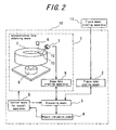
- FIG. 2 is a schematic view showing an apparatus for inspecting a concave-convex figure of tire used for inspecting a three-dimensional shape of this figure.
- An apparatus for inspecting a concave-convex figure of tire 10 comprises: a concave-convex data obtaining means 1 for obtaining a concave-convex distribution data in a predetermined tire surface region including the figure 20; a figure data storing means 2 for storing a database having data (master data) of a figure model being a form of respective figures including the figure 20 and an additional information data table including a figure arranging information; a processing means 3 for specifying a tire surface portion corresponding to this figure model, on the basis of the concave-convex data obtaining means 1 and the data of the figure model input from the figure data storing means 2 and for determining whether or not the three-dimensional shape of the figure is acceptable, on the basis of a coincidence between the concave-convex distribution data of the specified tire surface portion and the data of the figure
- the concave-convex data obtaining means 1 comprises: a semiconductor laser 6 for irradiating a plain beam (sheet light) 12 spread in a fan-like form; a two-dimensional camera 7 for picking-up a bright line 13 formed on a sidewall surface of the tire T by the sheet light 12; a tire rotation driving apparatus 8 for rotating the tire at a predetermined rotation speed or for transferring a tire pitch by pitch in a circumferential direction by a predetermined pitch; a shape data creating apparatus 9 for inputting an image data from the camera 7 picked-up at a predetermined interval in a circumferential direction of tire, extracting the bright line 13 only from respective image data, and creating the three-dimensional concave-convex distribution data along overall surface regions of an annular tire.
- a method of creating a profile of work (three-dimensional shape data) by gathering the images of bright lines formed on the work under such a condition that the sheet light is irradiated while transferring the work is generally called as a light-section method.
- the three-dimensional shape data can be accurately obtained directly from the picked-up images by utilizing the light-section method.
- the figure data storing means 2 stores the data (master data) of the figure model.
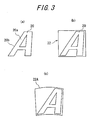
- Figs. 3a to 3c are schematic views respectively explaining a difference between the figure and the figure model
- Fig. 3a is a schematic view showing the figure 20
- Fig. 3b is a schematic view showing the figure model corresponding to the figure 20.
- the figure 20 indicates a character "A”.
- the figure is a portion to be inspected and indicates a portion obtained by joining a profile line 20b and an inner portion 20a formed by the profile lines 20b, while the figure model is a tool for being verified with the concave-convex distribution data.
- the figure model 22 is indicated by a rectangular region including the figure 20 and its circumferential region.
- the concave-convex distribution data created on the basis of the image data from the camera 7 show a surface profile of the actual tire as it is. Therefore, the actual concave-convex figure, which is obtained as the concave-convex distribution data and is formed on the surface of tire, has a shape such that an outer portion of tire in a radial direction is extended as compared with an inner portion of tire in a radial direction, with respect to the figure 20 exhibited in the figure model 22.
- a tire surface portion corresponding to the figure model 22 is searched, or, when it is determined whether or not the figure is accepted, it is necessary to control a dimension of the figure model in such a manner that it is deformed into a sector form in accordance with a tire size and corresponding to a surface portion to be adjusted.
- the search and the acceptance determination mentioned above are performed by using a figure model after effecting deformations such as a polar coordination conversion and a size deformation, in which an origin is a center of tire with respect to the figure model 22.
- a schematic view shown in Fig. 3c is a figure model after deformation 22A, in which the polar coordination conversion and the size deformation are effected to the figure model 22.
- the figure data storing means 2 stores the data (master data) of the figure model 22, which is a figure model before effecting the polar coordination conversion and the size deformation mentioned above and is exhibited by a rectangular coordinate system in which intersecting points are arranged at even intervals.
- the figure data storing means 2 stores the additional information data table including an arranging position information of the figure model 22, other than the data of the figure model 22, with respect to the tire to be inspected.
- the arranging position information is formed by gathering specs relating to a center position of the figure model, on the annular tire surface region shown in Fig. 1 .
- the arranging position information of the figure model 22 is stored as the data of the center position of the figure model 22 in place exhibited by a distance R from the tire center and an angle ⁇ in a circumferential direction on the basis of a predetermined mark and so on arranged on the surface of tire.
- the processing means 3 comprises the steps of: obtaining the concave-convex distribution data about respective area components in a predetermined tire surface region including the figure 20 from the concave-convex data obtaining means 1, on the basis of a command from the control means for overall apparatus 5; obtaining the data of the figure model and the figure arranging information, which are preliminarily prepared, from the figure data storing means 2; setting the search area in the tire surface region, on the basis of the figure arranging information preliminarily prepared with respect to the figure 20; changing a position of the tire surface portion, which is to be corresponding to the figure model, in the search area; specifying the tire surface portion at which a coincidence between the concave-convex distribution data of the tire surface portion and the data of the figure model, which are calculated at respective positions, is largest, as the portion corresponding to the figure model; measuring the coincidence between the concave-convex distribution data of the specified tire surface portion and the data of the figure model, with respect to the figure 20; and determining whether or not
- the data (master data) of the figure model mentioned above are created on the basis of a design CAD figure data of a die for forming the tire. Since the CAD figure data have no variation, in the method of creating the master data according to the invention, it is possible to create the accurate master data having no variation.
- a numeral 11 is a figure model creating apparatus used for the method of creating the master data for inspecting the concave-convex figure according to the invention, and the figure model creating apparatus 11 is realized by performing a software program.
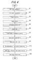
- Fig. 4 is a flow chart showing a process performed in the figure model creating apparatus 11.
- the step of creating the master data comprises: a CAD data processing step for cutting-out an image including the figure from tire CAD figures and creating a figure detail information by adding a figure position information and a figure height information; a gray scale transforming step for transforming the cut-out image into gray scale data corresponding to the height by using the figure height information in the figure detail information; and a shape deforming step for deforming a shape by using the figure position information in the figure detail information.
- the figure model creating apparatus 11 functions to call CAD data from the design CAD figure files (for example, DXF file) of the die for forming the tire and to indicate the tire CAD figure on a display (step 1). Then, a center position of the tire is calculated from the tire CAD figure (step 2). In this case, the center position of the tire may be indicated manually by an operator.
- the figure is selected from the tire CAD figure (step 3).
- the figure may be selected manually by an operator. If the figure is selected from the tire CAD figure, a circumscribed quadrangle of the figure is formed by tangent lines in a radial direction and in a circumferential direction of the tire, and the image including the figure is cut-out and is registered as the data (step 4).
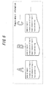
- Fig. 5 is a schematic view showing the arranging position of the figure on the tire CAD figure.
- the height (depth) of respective regions is set and registered in such a manner that an area surrounded by lines on the cut-out figure is recognized as a region having a constant height by using the figure height information derived from the tire CAD figure (step 6).
- the height may be set and registered by opening a numerical value input window and inputting the height of respective regions of the figure successively from the outside. Further, a figure attribute flag indicating a kind of the figure is input by opening the numerical value input window.
- the figure detail information is created from information obtained as mentioned above (step 7).
- Fig. 6 shows one embodiment of the figure detail information.
- the figure detail information includes, at least, image data, figure number, arranging position of figure, height information of figure, figure attribute flag, with respect to respective cut-out figure.
- the figure model creating apparatus 11 transforms the image cut-out by the CAD data processing into the gray scale image corresponding to the height by utilizing the figure height information in the figure detail information (step 8).
- the gray scale is defined by a value of "height range” previously set as an imaging parameter, and is indicated by a value of 256 gray level obtained by dividing for example "height range” into 0-255 (black - white).
- the setting value of "height range” may be set changeably.
- Fig. 7 is a schematic view showing one embodiment of the gray scale transforming step.
- the height range is controlled to be 0 - 2 mm, and the gray scale transformation is performed by using the figure detail information such as a height of 1.0 mm in a region of figure profile line, a height of 0.4 mm in a region of inner profile line and a height of 0 mm in a region of outer profile line.
- the height range of 0 - 2 mm is divided into 256 gray scale, a portion having a height of 1.0 mm becomes a gray scale of 128, a portion having a height of 0.4 mm becomes a gray scale of 51 and a portion having a height of 0 mm becomes a gray scale of 0 (black).
- the figure model creating apparatus 11 deforms the image data of the figure as mentioned below by utilizing information of the figure arranging position (R, ⁇ ) in the figure detail information.
- the image data of a figure 24 shown in Fig. 8a are sampled, at a position of a distance R from the tire center as shown in Fig. 8b , in accordance with a sampling interval ⁇ R from the tire center in a radial direction and a sampling interval ⁇ in a circumferential direction of the tire (step 9).
- the setting value of the sampling interval may be set changeably.
- Fig. 9 is a schematic view explaining the size deformation and the polar coordination - rectangular coordination conversion.
- the reason for performing the deformation in such a manner that the intersecting points are arranged at even intervals is that it is not affected by the tire size and the master data can be used for various tire sizes.
- the master data since it is not necessary to create the master data for all the tire sizes respectively, it is possible to minimize a work for constructing the database of the master data.
- the image size of the figure is controlled to be a dimension of the circumscribed quadrangle surrounding the region after deformation. As shown in Fig. 10 , the image size becomes a dimension indicated by lateral dimension of outer frame (px) x longitudinal direction of outer frame (py).
- the arranging standard position (X, Y), which is a standard position when arranging the figure, is defined in such a manner that a left-down corner of the outer frame is a standard point.
- the image data obtained as mentioned above are registered as the master data having for example a bit map format.
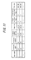
- the additional information data table including image number, arranging angle, arranging diameter, arranging standard position, image size, figure attribute flag, front-back determining flag, file name and so on is created (step 11).
- Fig. 11 one embodiment of the additional information data table is shown.
- the figure attribute flag indicates mold number, and character or a kind of figure such as "Made in Japan" on a week serial plate.
- the front-back determining flag indicates for example whether the figure is arranged in one side or in both sides.
- the database is constructed by the master data of the figure whose shape is deformed as mentioned above and the additional information data table (step 12).
- the shape deforming process is performed after the gray scale transforming process, but the gray scale transforming process may be performed after the shape deforming process.
Description
- The present invention relates to a method of creating master data used for inspecting concave-convex figure, which can inspect a shape of one or more figures formed by a concave-convex portion on a surface of tire.
- As a method of inspecting automatically a figure such as a character formed by a concave-convex portion on a surface of tire, there is known a method for inspecting whether the concave-convex portion is indicated adequately or not as a predetermined character string at a predetermined position (for example, referred to a patent literature 1), by: irradiating a light to a sidewall of tire to which the concave-convex portions is formed; picking-up a bright line on the sidewall formed by a light by means of an image pickup camera; reading and processing image data equivalent to a character or a character string; transforming the image data into a character string in accordance with the concave-convex portion; and comparing the transformed character string with a character string stored previously as master data.
Patent literature 1: Japanese Patent Laid-Open Publication No.10-115508 - However, in the known inspecting method, since a figure portion cut-out from an image information, which is obtained by measuring an appearance of tire actually, is treated as master data, the master data are affected by various characteristics such as resolution, accuracy, field of view, blind corner, that are originated from a measuring apparatus. In addition, since the master data include a positional error occurred every measurements, an occurrence of variation is not inhibited.
- Moreover, since a tire selected for creating master data have a variation and is not necessarily a standard center even if it lies in the standard, it is not possible to create the master data, which are a center of a comparison.
- Further, in the case such that the tires have various tire sizes, since it is necessary to perform the measurements for all the tire sizes, it takes a lot of time to create a database of the master data.
- Attention is drawn to the disclosures of
WO 03/023699 JP 63 201876 - The present invention has for its object to eliminate the drawbacks and to provide a method of creating master data used for inspecting a concave-convex figure, which can create accurate master data with no variation and can easily construct a database of the master data.
- In order to achieve the object mentioned above, according to a first aspect of the invention, a method is provided, according to
claim 1. - In the present invention, since the master data used for comparing with the concave-convex figure on the surface of the tire is created on the basis of the tire CAD drawings, there occurs no variation and thus the accurate master data can be created. Moreover, since it is possible to create the accurate master data having no variation, it is possible to improve a comparative accuracy when comparing with the concave-convex figure on the surface of tire.
- Further, in the known method, in the case such that the tires to be inspected have various tire sizes, it is necessary to perform the measurements of master data for all the tire sizes. However, in the present invention, since the master data can be created not depending on the tire size and one master data is sufficient for one figure, it is possible to minimize an energy for constructing the database of the master data.
-
- [
Fig. 1] Fig. 1 is a front view schematically showing a surface of sidewall of tire on which a plurality of figures are arranged. - [
Fig. 2] Fig. 2 is a schematic view illustrating an apparatus for inspecting a concave-convex figure of tire. - [
Fig. 3] Figs. 3a to 3c are schematic views respectively explaining a difference between the figure and the figure model. - [
Fig. 4] Fig. 4 is a flow chart showing a process performed by an apparatus for creating the figure model. - [
Fig. 5] Fig. 5 is a schematic view illustrating an arranging position of the figure on the CAD drawing. - [
Fig. 6] Fig. 6 is a schematic view depicting one embodiment of the figure detail information. - [
Fig. 7] Fig. 7 is a schematic view showing one embodiment of the gray scale transforming process. - [
Fig. 8] Figs. 8a to 8c are schematic views respectively explaining the shape transforming process. - [
Fig. 9] Fig. 9 is a schematic views illustrating the size transformation and the polar coordinate - rectangular coordinates transformation. - [
Fig. 10] Fig. 10 is a schematic view explaining the image size and the arranging standard position. - [
Fig. 11] Fig. 11 is a schematic view depicting one embodiment of the additional information data table. - Prior to explain a method of creating master data according to the invention, an apparatus for inspecting a concave-convex figure of tire, in which the master data created according to the method of the invention are used, will be explained first.
-
Fig. 1 is a front view schematically showing a surface of sidewall of tire T, to which a plurality of figures created by applying a concave-convex portion are formed, and, hereinafter, the explanation is made to a case such that a three-dimensional shape of a figure 20 indicated at "a" portion inFig. 1 . It should be noted that the figures indicated at "b" portion or "c" portion other than the "a" portion inFig. 1 can be inspected in the same manner as that of the "a" portion. -
Fig. 2 is a schematic view showing an apparatus for inspecting a concave-convex figure of tire used for inspecting a three-dimensional shape of this figure. An apparatus for inspecting a concave-convex figure oftire 10 comprises: a concave-convexdata obtaining means 1 for obtaining a concave-convex distribution data in a predetermined tire surface region including the figure 20; a figure data storing means 2 for storing a database having data (master data) of a figure model being a form of respective figures including the figure 20 and an additional information data table including a figure arranging information; a processing means 3 for specifying a tire surface portion corresponding to this figure model, on the basis of the concave-convexdata obtaining means 1 and the data of the figure model input from the figure data storing means 2 and for determining whether or not the three-dimensional shape of the figure is acceptable, on the basis of a coincidence between the concave-convex distribution data of the specified tire surface portion and the data of the figure model; a result indication means 4 for outputting a determined result of the passing state; and a control means foroverall apparatus 5 for controlling these means. - The concave-convex
data obtaining means 1 comprises: asemiconductor laser 6 for irradiating a plain beam (sheet light) 12 spread in a fan-like form; a two-dimensional camera 7 for picking-up abright line 13 formed on a sidewall surface of the tire T by thesheet light 12; a tirerotation driving apparatus 8 for rotating the tire at a predetermined rotation speed or for transferring a tire pitch by pitch in a circumferential direction by a predetermined pitch; a shapedata creating apparatus 9 for inputting an image data from thecamera 7 picked-up at a predetermined interval in a circumferential direction of tire, extracting thebright line 13 only from respective image data, and creating the three-dimensional concave-convex distribution data along overall surface regions of an annular tire. - A method of creating a profile of work (three-dimensional shape data) by gathering the images of bright lines formed on the work under such a condition that the sheet light is irradiated while transferring the work is generally called as a light-section method. In the concave-convex data obtaining means 1 according to this embodiment, the three-dimensional shape data can be accurately obtained directly from the picked-up images by utilizing the light-section method.
- Moreover, the figure data storing means 2 stores the data (master data) of the figure model.
Figs. 3a to 3c are schematic views respectively explaining a difference between the figure and the figure model, andFig. 3a is a schematic view showing the figure 20 andFig. 3b is a schematic view showing the figure model corresponding to the figure 20. In this embodiment, the figure 20 indicates a character "A". Generally, the figure is a portion to be inspected and indicates a portion obtained by joining aprofile line 20b and aninner portion 20a formed by theprofile lines 20b, while the figure model is a tool for being verified with the concave-convex distribution data. In the embodiment shown inFig. 3b , thefigure model 22 is indicated by a rectangular region including the figure 20 and its circumferential region. - The concave-convex distribution data created on the basis of the image data from the
camera 7 show a surface profile of the actual tire as it is. Therefore, the actual concave-convex figure, which is obtained as the concave-convex distribution data and is formed on the surface of tire, has a shape such that an outer portion of tire in a radial direction is extended as compared with an inner portion of tire in a radial direction, with respect to the figure 20 exhibited in thefigure model 22. In this case, when a tire surface portion corresponding to thefigure model 22 is searched, or, when it is determined whether or not the figure is accepted, it is necessary to control a dimension of the figure model in such a manner that it is deformed into a sector form in accordance with a tire size and corresponding to a surface portion to be adjusted. To this end, the search and the acceptance determination mentioned above are performed by using a figure model after effecting deformations such as a polar coordination conversion and a size deformation, in which an origin is a center of tire with respect to thefigure model 22. A schematic view shown inFig. 3c is a figure model afterdeformation 22A, in which the polar coordination conversion and the size deformation are effected to thefigure model 22. - As mentioned above, in order to create the figure model used for determining whether or not the tires having a plurality of sizes are accepted, the figure data storing means 2 stores the data (master data) of the
figure model 22, which is a figure model before effecting the polar coordination conversion and the size deformation mentioned above and is exhibited by a rectangular coordinate system in which intersecting points are arranged at even intervals. - In addition, the figure data storing means 2 stores the additional information data table including an arranging position information of the
figure model 22, other than the data of thefigure model 22, with respect to the tire to be inspected. The arranging position information is formed by gathering specs relating to a center position of the figure model, on the annular tire surface region shown inFig. 1 . For example, the arranging position information of thefigure model 22 is stored as the data of the center position of thefigure model 22 in place exhibited by a distance R from the tire center and an angle θ in a circumferential direction on the basis of a predetermined mark and so on arranged on the surface of tire. - The processing means 3 comprises the steps of: obtaining the concave-convex distribution data about respective area components in a predetermined tire surface region including the figure 20 from the concave-convex
data obtaining means 1, on the basis of a command from the control means foroverall apparatus 5; obtaining the data of the figure model and the figure arranging information, which are preliminarily prepared, from the figure data storing means 2; setting the search area in the tire surface region, on the basis of the figure arranging information preliminarily prepared with respect to the figure 20; changing a position of the tire surface portion, which is to be corresponding to the figure model, in the search area; specifying the tire surface portion at which a coincidence between the concave-convex distribution data of the tire surface portion and the data of the figure model, which are calculated at respective positions, is largest, as the portion corresponding to the figure model; measuring the coincidence between the concave-convex distribution data of the specified tire surface portion and the data of the figure model, with respect to the figure 20; and determining whether or not the three-dimensional shape of the figure 20 is accepted on the basis of the coincidence mentioned above. - In the method of creating the master data for inspecting the concave-convex figure according to the invention, the data (master data) of the figure model mentioned above are created on the basis of a design CAD figure data of a die for forming the tire. Since the CAD figure data have no variation, in the method of creating the master data according to the invention, it is possible to create the accurate master data having no variation.
- Hereinafter, the method of creating the master data for inspecting the concave-convex figure according to the invention will be explained.
- In
Fig. 2 , anumeral 11 is a figure model creating apparatus used for the method of creating the master data for inspecting the concave-convex figure according to the invention, and the figuremodel creating apparatus 11 is realized by performing a software program.Fig. 4 is a flow chart showing a process performed in the figuremodel creating apparatus 11. - The step of creating the master data comprises: a CAD data processing step for cutting-out an image including the figure from tire CAD figures and creating a figure detail information by adding a figure position information and a figure height information; a gray scale transforming step for transforming the cut-out image into gray scale data corresponding to the height by using the figure height information in the figure detail information; and a shape deforming step for deforming a shape by using the figure position information in the figure detail information.
- First, the CAD data processing step will be explained. The figure
model creating apparatus 11 functions to call CAD data from the design CAD figure files (for example, DXF file) of the die for forming the tire and to indicate the tire CAD figure on a display (step 1). Then, a center position of the tire is calculated from the tire CAD figure (step 2). In this case, the center position of the tire may be indicated manually by an operator. - Then, the figure is selected from the tire CAD figure (step 3). In this case, the figure may be selected manually by an operator. If the figure is selected from the tire CAD figure, a circumscribed quadrangle of the figure is formed by tangent lines in a radial direction and in a circumferential direction of the tire, and the image including the figure is cut-out and is registered as the data (step 4).
- Then, the arranging position of the figure is set and registered by a distance R in a radial direction from a tire center of the circumscribed quadrangle (arranging diameter) and a displacement angle (arranging angle) θ in a radial direction of tire from a designated position (step 5).
Fig. 5 is a schematic view showing the arranging position of the figure on the tire CAD figure. - Then, the height (depth) of respective regions is set and registered in such a manner that an area surrounded by lines on the cut-out figure is recognized as a region having a constant height by using the figure height information derived from the tire CAD figure (step 6). The height may be set and registered by opening a numerical value input window and inputting the height of respective regions of the figure successively from the outside. Further, a figure attribute flag indicating a kind of the figure is input by opening the numerical value input window.
- The figure detail information is created from information obtained as mentioned above (step 7).
Fig. 6 shows one embodiment of the figure detail information. The figure detail information includes, at least, image data, figure number, arranging position of figure, height information of figure, figure attribute flag, with respect to respective cut-out figure. - Then, the gray scale transforming step will be explained. The figure
model creating apparatus 11 transforms the image cut-out by the CAD data processing into the gray scale image corresponding to the height by utilizing the figure height information in the figure detail information (step 8). The gray scale is defined by a value of "height range" previously set as an imaging parameter, and is indicated by a value of 256 gray level obtained by dividing for example "height range" into 0-255 (black - white). The setting value of "height range" may be set changeably. -
Fig. 7 is a schematic view showing one embodiment of the gray scale transforming step. InFig. 7 , the height range is controlled to be 0 - 2 mm, and the gray scale transformation is performed by using the figure detail information such as a height of 1.0 mm in a region of figure profile line, a height of 0.4 mm in a region of inner profile line and a height of 0 mm in a region of outer profile line. If the height range of 0 - 2 mm is divided into 256 gray scale, a portion having a height of 1.0 mm becomes a gray scale of 128, a portion having a height of 0.4 mm becomes a gray scale of 51 and a portion having a height of 0 mm becomes a gray scale of 0 (black). - Then, the shape deforming step will be explained. The figure
model creating apparatus 11 deforms the image data of the figure as mentioned below by utilizing information of the figure arranging position (R, θ) in the figure detail information. - First, the image data of a figure 24 shown in
Fig. 8a are sampled, at a position of a distance R from the tire center as shown inFig. 8b , in accordance with a sampling interval ΔR from the tire center in a radial direction and a sampling interval Δθ in a circumferential direction of the tire (step 9). The setting value of the sampling interval may be set changeably. - Then, the size deformation and the polar coordination - rectangular coordination conversion are performed in such a manner that the intersecting points are arranged at even intervals, so as to obtain the image data of the figure 26 shown in
Fig. 8c (step 10).Fig. 9 is a schematic view explaining the size deformation and the polar coordination - rectangular coordination conversion.
In this manner, the reason for performing the deformation in such a manner that the intersecting points are arranged at even intervals is that it is not affected by the tire size and the master data can be used for various tire sizes. In the present invention, since it is not necessary to create the master data for all the tire sizes respectively, it is possible to minimize a work for constructing the database of the master data. - The image size of the figure is controlled to be a dimension of the circumscribed quadrangle surrounding the region after deformation. As shown in
Fig. 10 , the image size becomes a dimension indicated by lateral dimension of outer frame (px) x longitudinal direction of outer frame (py). The arranging standard position (X, Y), which is a standard position when arranging the figure, is defined in such a manner that a left-down corner of the outer frame is a standard point. The image data obtained as mentioned above are registered as the master data having for example a bit map format. - Then, the additional information data table including image number, arranging angle, arranging diameter, arranging standard position, image size, figure attribute flag, front-back determining flag, file name and so on is created (step 11). In
Fig. 11 , one embodiment of the additional information data table is shown. The figure attribute flag indicates mold number, and character or a kind of figure such as "Made in Japan" on a week serial plate. The front-back determining flag indicates for example whether the figure is arranged in one side or in both sides. - Then, the database is constructed by the master data of the figure whose shape is deformed as mentioned above and the additional information data table (step 12).
- In the embodiments mentioned above, the shape deforming process is performed after the gray scale transforming process, but the gray scale transforming process may be performed after the shape deforming process.
Claims (1)
- A method of creating master data from tire computer-aided design, hereinafter referred to as CAD, drawings, the master data being for inspecting a figure having concave and convex portions formed on a surface of a tire, such inspecting being by utilizing a light-section method in which use is made of laser light having a fan-like form, the CAD drawings having figures deformed according to a tire size and deformed into a sector form according to an arranging position in a radial direction from a tire center, and having height information of protrusion or indentation of respective regions of the figure, comprising the steps of:cutting out (S4) an image including the figure by selecting a region including the figure from the tire CAD drawings by forming a circumscribed quadrangle around the figure by tangent lines in a radial direction and in a circumferential direction of the tire;transforming (S8) respective regions of the cut-out image into a gray scale image in accordance with said height information of respective regions obtained from the tire CAD drawings; anddeforming (S10) the cut-out image or the image converted into gray scale by performing a polar to rectangular coordination conversion in such a manner that the cut-out image or the image converted into gray scale is sampled in accordance with a predetermined angle in a circumferential direction of the tire and then a deformation is performed in such a manner that sampling intervals are arranged at even intervals in a circumferential direction of the tire.
Priority Applications (1)
| Application Number | Priority Date | Filing Date | Title |
|---|---|---|---|
| PL06766905T PL1901059T3 (en) | 2005-06-28 | 2006-06-19 | Method for forming master data for inspecting protruding and recessed figure |
Applications Claiming Priority (2)
| Application Number | Priority Date | Filing Date | Title |
|---|---|---|---|
| JP2005188161A JP4881584B2 (en) | 2005-06-28 | 2005-06-28 | How to create master data for inspection of uneven figures |
| PCT/JP2006/312241 WO2007000909A1 (en) | 2005-06-28 | 2006-06-19 | Method for forming master data for inspecting protruding and recessed figure |
Publications (3)
| Publication Number | Publication Date |
|---|---|
| EP1901059A1 EP1901059A1 (en) | 2008-03-19 |
| EP1901059A4 EP1901059A4 (en) | 2011-12-21 |
| EP1901059B1 true EP1901059B1 (en) | 2015-04-01 |
Family
ID=37595163
Family Applications (1)
| Application Number | Title | Priority Date | Filing Date |
|---|---|---|---|
| EP06766905.1A Expired - Fee Related EP1901059B1 (en) | 2005-06-28 | 2006-06-19 | Method for forming master data for inspecting protruding and recessed figure |
Country Status (9)
| Country | Link |
|---|---|
| US (1) | US8086019B2 (en) |
| EP (1) | EP1901059B1 (en) |
| JP (1) | JP4881584B2 (en) |
| CN (1) | CN101213440B (en) |
| BR (1) | BRPI0612696B1 (en) |
| ES (1) | ES2538713T3 (en) |
| HU (1) | HUE026478T2 (en) |
| PL (1) | PL1901059T3 (en) |
| WO (1) | WO2007000909A1 (en) |
Families Citing this family (14)
| Publication number | Priority date | Publication date | Assignee | Title |
|---|---|---|---|---|
| US7684609B1 (en) * | 2006-05-25 | 2010-03-23 | Kla-Tencor Technologies Corporation | Defect review using image segmentation |
| JP5046688B2 (en) * | 2007-03-08 | 2012-10-10 | 株式会社神戸製鋼所 | Tire shape detection device and tire shape detection method |
| JP5331621B2 (en) * | 2009-09-01 | 2013-10-30 | 株式会社日立製作所 | Vehicle inspection device |
| JP5620139B2 (en) * | 2010-04-02 | 2014-11-05 | 株式会社ブリヂストン | Tire appearance inspection method and appearance inspection apparatus |
| JP5973863B2 (en) * | 2012-10-02 | 2016-08-23 | 住友ゴム工業株式会社 | Inspection method for core assembly |
| JP5775132B2 (en) * | 2013-11-01 | 2015-09-09 | 株式会社ブリヂストン | Tire inspection equipment |
| JP6614137B2 (en) | 2014-04-07 | 2019-12-04 | 横浜ゴム株式会社 | Tire mold marking inspection method and apparatus |
| CN107110639B (en) | 2014-12-22 | 2020-10-09 | 倍耐力轮胎股份公司 | Device for inspecting tyres on a tyre production line |
| KR102596252B1 (en) * | 2014-12-22 | 2023-10-31 | 피렐리 타이어 소시에떼 퍼 아찌오니 | Method and apparatus for checking tyres in a production line |
| CN105069749B (en) * | 2015-07-22 | 2018-04-13 | 广东工业大学 | A kind of joining method of tire-mold image |
| CN105718672B (en) * | 2016-01-22 | 2019-02-12 | 集美大学 | A kind of CAD Object selection method |
| US11472234B2 (en) * | 2016-03-04 | 2022-10-18 | TIREAUDIT.COM, Inc. | Mesh registration system and method for diagnosing tread wear |
| CN105975802A (en) * | 2016-07-05 | 2016-09-28 | 北京数码大方科技股份有限公司 | Grading method and device for CAD drawing |
| CN112747685A (en) * | 2019-10-31 | 2021-05-04 | 南宁富桂精密工业有限公司 | Grain depth detection system and method thereof |
Family Cites Families (35)
| Publication number | Priority date | Publication date | Assignee | Title |
|---|---|---|---|---|
| US3918816A (en) * | 1974-04-22 | 1975-11-11 | Autech Corp | Tire inspection apparatus |
| US4095464A (en) * | 1976-06-21 | 1978-06-20 | The Goodyear Tire & Rubber Company | Method and apparatus for tire tread analysis |
| JPS63201876A (en) * | 1987-02-18 | 1988-08-19 | Hitachi Ltd | Picture processing system and device |
| US4873651A (en) * | 1987-04-21 | 1989-10-10 | Case Western Reserve University | Method and apparatus for reconstructing three-dimensional surfaces from two-dimensional images |
| JPH0244202A (en) * | 1988-08-05 | 1990-02-14 | Bridgestone Corp | Apparatus for detecting end position of object |
| JP3009205B2 (en) * | 1990-11-02 | 2000-02-14 | 株式会社日立製作所 | Inspection method and apparatus |
| US5245867A (en) * | 1991-12-16 | 1993-09-21 | Bridgestone Corporation | Method and apparatus for measuring tire parameters |
| US5335290A (en) * | 1992-04-06 | 1994-08-02 | Ricoh Corporation | Segmentation of text, picture and lines of a document image |
| JPH07152860A (en) * | 1993-11-29 | 1995-06-16 | Toyo Tire & Rubber Co Ltd | Device for reading rugged character |
| JPH07237270A (en) * | 1994-02-28 | 1995-09-12 | Shimadzu Corp | Tire discriminating device |
| JP3716060B2 (en) * | 1996-10-14 | 2005-11-16 | 株式会社ブリヂストン | Tire marking inspection equipment |
| SE509327C2 (en) * | 1996-11-01 | 1999-01-11 | C Technologies Ab | Method and device for registering characters using a pen |
| JPH10160437A (en) * | 1996-12-03 | 1998-06-19 | Bridgestone Corp | Method and device for judging external shape of tire |
| US5974168A (en) * | 1998-04-16 | 1999-10-26 | International Business Machines Corporation | Acquiring bump maps from curved objects |
| US6762768B2 (en) * | 1998-06-01 | 2004-07-13 | Ati Technologies, Inc. | Method and apparatus for rendering an object using texture variant information |
| US6828980B1 (en) * | 2000-10-02 | 2004-12-07 | Nvidia Corporation | System, method and computer program product for z-texture mapping |
| US6731298B1 (en) * | 2000-10-02 | 2004-05-04 | Nvidia Corporation | System, method and article of manufacture for z-texture mapping |
| DE10062251C2 (en) * | 2000-12-14 | 2002-12-12 | Fraunhofer Ges Forschung | Device and method for checking the quality of a body |
| DE10143522C2 (en) * | 2001-09-05 | 2003-07-10 | Fraunhofer Ges Forschung | Method and device for examining an object |
| FR2830079B1 (en) * | 2001-09-26 | 2004-04-30 | Holo 3 | METHOD AND DEVICE FOR MEASURING AT LEAST ONE GEOMETRIC SIZE OF AN OPTICALLY REFLECTIVE SURFACE |
| US7050605B2 (en) * | 2002-01-02 | 2006-05-23 | Jonas Elliott Gerson | Designing tread with fractal characteristics |
| US6728593B2 (en) * | 2002-06-06 | 2004-04-27 | The Hong Kong Polytechnic University | System for analysis of fabric surface |
| US6802130B2 (en) * | 2002-09-30 | 2004-10-12 | Bridgestone/Firestone North American Tire, Llc | Alignment device for rotating tire laser mapping machine |
| JP2004252603A (en) * | 2003-02-18 | 2004-09-09 | Canon Inc | Three-dimensional data processing method |
| DE10319099B4 (en) * | 2003-04-28 | 2005-09-08 | Steinbichler Optotechnik Gmbh | Method for interference measurement of an object, in particular a tire |
| CN1259543C (en) * | 2003-06-11 | 2006-06-14 | 北京航空航天大学 | Laser vision on-line automatic measuring method for tire multiple geometrical parameters |
| JP4679073B2 (en) * | 2004-05-18 | 2011-04-27 | 株式会社ブリヂストン | Tire unevenness pattern inspection method and tire unevenness pattern inspection apparatus |
| JP4203498B2 (en) * | 2005-09-22 | 2009-01-07 | アドバンスド・マスク・インスペクション・テクノロジー株式会社 | Image correction apparatus, pattern inspection apparatus, image correction method, and pattern defect inspection method |
| US7684609B1 (en) * | 2006-05-25 | 2010-03-23 | Kla-Tencor Technologies Corporation | Defect review using image segmentation |
| JP5019849B2 (en) * | 2006-11-02 | 2012-09-05 | 株式会社ブリヂストン | Tire surface inspection method and apparatus |
| JP5046688B2 (en) * | 2007-03-08 | 2012-10-10 | 株式会社神戸製鋼所 | Tire shape detection device and tire shape detection method |
| CN101266180A (en) * | 2007-03-16 | 2008-09-17 | 清华大学 | Ionization gage |
| EP2172737B1 (en) * | 2007-08-06 | 2013-04-24 | Kabushiki Kaisha Kobe Seiko Sho | Tire shape measuring system |
| DE102010003376B4 (en) * | 2009-03-30 | 2021-04-01 | Koh Young Technology Inc. | Investigation procedure |
| JP5368866B2 (en) * | 2009-04-21 | 2013-12-18 | 株式会社日本自動車部品総合研究所 | Rotating electric machine |
-
2005
- 2005-06-28 JP JP2005188161A patent/JP4881584B2/en not_active Expired - Fee Related
-
2006
- 2006-06-19 US US11/994,197 patent/US8086019B2/en not_active Expired - Fee Related
- 2006-06-19 CN CN2006800234968A patent/CN101213440B/en not_active Expired - Fee Related
- 2006-06-19 BR BRPI0612696-0A patent/BRPI0612696B1/en not_active IP Right Cessation
- 2006-06-19 PL PL06766905T patent/PL1901059T3/en unknown
- 2006-06-19 HU HUE06766905A patent/HUE026478T2/en unknown
- 2006-06-19 EP EP06766905.1A patent/EP1901059B1/en not_active Expired - Fee Related
- 2006-06-19 ES ES06766905.1T patent/ES2538713T3/en active Active
- 2006-06-19 WO PCT/JP2006/312241 patent/WO2007000909A1/en active Application Filing
Also Published As
| Publication number | Publication date |
|---|---|
| JP2007011462A (en) | 2007-01-18 |
| US8086019B2 (en) | 2011-12-27 |
| CN101213440B (en) | 2010-12-08 |
| ES2538713T3 (en) | 2015-06-23 |
| HUE026478T2 (en) | 2016-06-28 |
| EP1901059A1 (en) | 2008-03-19 |
| EP1901059A4 (en) | 2011-12-21 |
| US20090226073A1 (en) | 2009-09-10 |
| JP4881584B2 (en) | 2012-02-22 |
| BRPI0612696B1 (en) | 2017-12-05 |
| WO2007000909A1 (en) | 2007-01-04 |
| BRPI0612696A2 (en) | 2010-11-30 |
| PL1901059T3 (en) | 2015-08-31 |
| CN101213440A (en) | 2008-07-02 |
Similar Documents
| Publication | Publication Date | Title |
|---|---|---|
| EP1901059B1 (en) | Method for forming master data for inspecting protruding and recessed figure | |
| US10346971B2 (en) | Optimized method for analyzing the conformity of the surface of a tire | |
| JP4679073B2 (en) | Tire unevenness pattern inspection method and tire unevenness pattern inspection apparatus | |
| CN102135417B (en) | Full-automatic three-dimension characteristic extracting method | |
| US6968080B2 (en) | Method and apparatus for generating part programs for use in image-measuring instruments, and image-measuring instrument and method of displaying measured results therefrom | |
| JP5124997B2 (en) | Tire mold side plate inspection method and inspection apparatus, tire mold side plate type determination method and determination apparatus, tire mold processing step inspection method and inspection apparatus | |
| JP5100249B2 (en) | Information processing method, information processing apparatus, and program | |
| US20130266189A1 (en) | Method for the pre-processing of a three-dimensional image of the surface of a tyre using successive b-spline deformations | |
| EP2520992B1 (en) | Method and computer system for characterizing a sheet metal part | |
| US20100114350A1 (en) | Method of determining mesh data and method of correcting model data | |
| CN108472706B (en) | Deformation processing support system and deformation processing support method | |
| US8160349B2 (en) | Pattern shape evaluation method, program, and semiconductor device manufacturing method | |
| US10434555B2 (en) | Metrology Assisted Part Forming System and Method | |
| US11151735B1 (en) | Deformation processing support system and deformation processing support method | |
| JP7058170B2 (en) | Tire mold side plate inspection method | |
| US10739750B2 (en) | Method for correcting deviations in a production process of an article using a head-mounted display | |
| JP3589512B2 (en) | Inspection point marking method for microfabricated products, automatic dimension inspection method and automatic dimension inspection device | |
| JP4269678B2 (en) | Measurement data comparison device and shape quality evaluation system | |
| JP2003340528A (en) | Device and method for evaluating dimensional accuracy of press-formed product |
Legal Events
| Date | Code | Title | Description |
|---|---|---|---|
| PUAI | Public reference made under article 153(3) epc to a published international application that has entered the european phase |
Free format text: ORIGINAL CODE: 0009012 |
|
| 17P | Request for examination filed |
Effective date: 20071228 |
|
| AK | Designated contracting states |
Kind code of ref document: A1 Designated state(s): DE ES FR HU IT PL |
|
| DAX | Request for extension of the european patent (deleted) | ||
| RBV | Designated contracting states (corrected) |
Designated state(s): DE ES FR HU IT PL |
|
| DAX | Request for extension of the european patent (deleted) | ||
| REG | Reference to a national code |
Ref country code: DE Ref legal event code: R079 Ref document number: 602006044969 Country of ref document: DE Free format text: PREVIOUS MAIN CLASS: G01N0021880000 Ipc: B60C0013000000 |
|
| A4 | Supplementary search report drawn up and despatched |
Effective date: 20111121 |
|
| RIC1 | Information provided on ipc code assigned before grant |
Ipc: B60C 13/00 20060101AFI20111115BHEP Ipc: G06T 7/00 20060101ALI20111115BHEP Ipc: G01M 17/02 20060101ALI20111115BHEP Ipc: G06K 9/62 20060101ALI20111115BHEP |
|
| 17Q | First examination report despatched |
Effective date: 20130315 |
|
| GRAP | Despatch of communication of intention to grant a patent |
Free format text: ORIGINAL CODE: EPIDOSNIGR1 |
|
| INTG | Intention to grant announced |
Effective date: 20141010 |
|
| GRAS | Grant fee paid |
Free format text: ORIGINAL CODE: EPIDOSNIGR3 |
|
| GRAA | (expected) grant |
Free format text: ORIGINAL CODE: 0009210 |
|
| AK | Designated contracting states |
Kind code of ref document: B1 Designated state(s): DE ES FR HU IT PL |
|
| REG | Reference to a national code |
Ref country code: DE Ref legal event code: R096 Ref document number: 602006044969 Country of ref document: DE Effective date: 20150521 |
|
| REG | Reference to a national code |
Ref country code: ES Ref legal event code: FG2A Ref document number: 2538713 Country of ref document: ES Kind code of ref document: T3 Effective date: 20150623 |
|
| REG | Reference to a national code |
Ref country code: PL Ref legal event code: T3 |
|
| REG | Reference to a national code |
Ref country code: DE Ref legal event code: R097 Ref document number: 602006044969 Country of ref document: DE |
|
| PLBE | No opposition filed within time limit |
Free format text: ORIGINAL CODE: 0009261 |
|
| STAA | Information on the status of an ep patent application or granted ep patent |
Free format text: STATUS: NO OPPOSITION FILED WITHIN TIME LIMIT |
|
| 26N | No opposition filed |
Effective date: 20160105 |
|
| REG | Reference to a national code |
Ref country code: FR Ref legal event code: PLFP Year of fee payment: 11 |
|
| REG | Reference to a national code |
Ref country code: HU Ref legal event code: AG4A Ref document number: E026478 Country of ref document: HU |
|
| REG | Reference to a national code |
Ref country code: FR Ref legal event code: PLFP Year of fee payment: 12 |
|
| REG | Reference to a national code |
Ref country code: FR Ref legal event code: PLFP Year of fee payment: 13 |
|
| PGFP | Annual fee paid to national office [announced via postgrant information from national office to epo] |
Ref country code: FR Payment date: 20200619 Year of fee payment: 15 Ref country code: DE Payment date: 20200618 Year of fee payment: 15 |
|
| PGFP | Annual fee paid to national office [announced via postgrant information from national office to epo] |
Ref country code: PL Payment date: 20200520 Year of fee payment: 15 |
|
| PGFP | Annual fee paid to national office [announced via postgrant information from national office to epo] |
Ref country code: ES Payment date: 20200824 Year of fee payment: 15 |
|
| PGFP | Annual fee paid to national office [announced via postgrant information from national office to epo] |
Ref country code: IT Payment date: 20200625 Year of fee payment: 15 Ref country code: HU Payment date: 20200718 Year of fee payment: 15 |
|
| REG | Reference to a national code |
Ref country code: DE Ref legal event code: R119 Ref document number: 602006044969 Country of ref document: DE |
|
| PG25 | Lapsed in a contracting state [announced via postgrant information from national office to epo] |
Ref country code: HU Free format text: LAPSE BECAUSE OF NON-PAYMENT OF DUE FEES Effective date: 20210620 Ref country code: DE Free format text: LAPSE BECAUSE OF NON-PAYMENT OF DUE FEES Effective date: 20220101 |
|
| PG25 | Lapsed in a contracting state [announced via postgrant information from national office to epo] |
Ref country code: FR Free format text: LAPSE BECAUSE OF NON-PAYMENT OF DUE FEES Effective date: 20210630 |
|
| PG25 | Lapsed in a contracting state [announced via postgrant information from national office to epo] |
Ref country code: IT Free format text: LAPSE BECAUSE OF NON-PAYMENT OF DUE FEES Effective date: 20210619 |
|
| REG | Reference to a national code |
Ref country code: ES Ref legal event code: FD2A Effective date: 20220826 |
|
| PG25 | Lapsed in a contracting state [announced via postgrant information from national office to epo] |
Ref country code: ES Free format text: LAPSE BECAUSE OF NON-PAYMENT OF DUE FEES Effective date: 20210620 |
|
| PG25 | Lapsed in a contracting state [announced via postgrant information from national office to epo] |
Ref country code: PL Free format text: LAPSE BECAUSE OF NON-PAYMENT OF DUE FEES Effective date: 20210619 |